EP3548397B1 - Getränkebeutel - Google Patents
Getränkebeutel Download PDFInfo
- Publication number
- EP3548397B1 EP3548397B1 EP17817816.6A EP17817816A EP3548397B1 EP 3548397 B1 EP3548397 B1 EP 3548397B1 EP 17817816 A EP17817816 A EP 17817816A EP 3548397 B1 EP3548397 B1 EP 3548397B1
- Authority
- EP
- European Patent Office
- Prior art keywords
- pouch
- heat seal
- line
- straw
- weakness
- Prior art date
- Legal status (The legal status is an assumption and is not a legal conclusion. Google has not performed a legal analysis and makes no representation as to the accuracy of the status listed.)
- Active
Links
Images


Classifications
-
- B—PERFORMING OPERATIONS; TRANSPORTING
- B65—CONVEYING; PACKING; STORING; HANDLING THIN OR FILAMENTARY MATERIAL
- B65D—CONTAINERS FOR STORAGE OR TRANSPORT OF ARTICLES OR MATERIALS, e.g. BAGS, BARRELS, BOTTLES, BOXES, CANS, CARTONS, CRATES, DRUMS, JARS, TANKS, HOPPERS, FORWARDING CONTAINERS; ACCESSORIES, CLOSURES, OR FITTINGS THEREFOR; PACKAGING ELEMENTS; PACKAGES
- B65D77/00—Packages formed by enclosing articles or materials in preformed containers, e.g. boxes, cartons, sacks or bags
- B65D77/22—Details
- B65D77/24—Inserts or accessories added or incorporated during filling of containers
- B65D77/28—Cards, coupons, or drinking straws
- B65D77/283—Cards, coupons, or drinking straws located initially inside the container, whereby the straw is revealed only upon opening the container, e.g. pop-up straws
-
- B—PERFORMING OPERATIONS; TRANSPORTING
- B65—CONVEYING; PACKING; STORING; HANDLING THIN OR FILAMENTARY MATERIAL
- B65D—CONTAINERS FOR STORAGE OR TRANSPORT OF ARTICLES OR MATERIALS, e.g. BAGS, BARRELS, BOTTLES, BOXES, CANS, CARTONS, CRATES, DRUMS, JARS, TANKS, HOPPERS, FORWARDING CONTAINERS; ACCESSORIES, CLOSURES, OR FITTINGS THEREFOR; PACKAGING ELEMENTS; PACKAGES
- B65D75/00—Packages comprising articles or materials partially or wholly enclosed in strips, sheets, blanks, tubes or webs of flexible sheet material, e.g. in folded wrappers
- B65D75/008—Standing pouches, i.e. "Standbeutel"
-
- B—PERFORMING OPERATIONS; TRANSPORTING
- B65—CONVEYING; PACKING; STORING; HANDLING THIN OR FILAMENTARY MATERIAL
- B65D—CONTAINERS FOR STORAGE OR TRANSPORT OF ARTICLES OR MATERIALS, e.g. BAGS, BARRELS, BOTTLES, BOXES, CANS, CARTONS, CRATES, DRUMS, JARS, TANKS, HOPPERS, FORWARDING CONTAINERS; ACCESSORIES, CLOSURES, OR FITTINGS THEREFOR; PACKAGING ELEMENTS; PACKAGES
- B65D75/00—Packages comprising articles or materials partially or wholly enclosed in strips, sheets, blanks, tubes or webs of flexible sheet material, e.g. in folded wrappers
- B65D75/04—Articles or materials wholly enclosed in single sheets or wrapper blanks
- B65D75/20—Articles or materials wholly enclosed in single sheets or wrapper blanks in sheets or blanks doubled around contents and having their opposed free margins united, e.g. by pressure-sensitive adhesive, crimping, heat-sealing, or welding
-
- B—PERFORMING OPERATIONS; TRANSPORTING
- B65—CONVEYING; PACKING; STORING; HANDLING THIN OR FILAMENTARY MATERIAL
- B65D—CONTAINERS FOR STORAGE OR TRANSPORT OF ARTICLES OR MATERIALS, e.g. BAGS, BARRELS, BOTTLES, BOXES, CANS, CARTONS, CRATES, DRUMS, JARS, TANKS, HOPPERS, FORWARDING CONTAINERS; ACCESSORIES, CLOSURES, OR FITTINGS THEREFOR; PACKAGING ELEMENTS; PACKAGES
- B65D75/00—Packages comprising articles or materials partially or wholly enclosed in strips, sheets, blanks, tubes or webs of flexible sheet material, e.g. in folded wrappers
- B65D75/52—Details
- B65D75/58—Opening or contents-removing devices added or incorporated during package manufacture
- B65D75/5816—Opening or contents-removing devices added or incorporated during package manufacture for tearing a corner or other small portion next to the edge, e.g. a U-shaped portion
- B65D75/5822—Opening or contents-removing devices added or incorporated during package manufacture for tearing a corner or other small portion next to the edge, e.g. a U-shaped portion and defining, after tearing, a small dispensing spout, a small orifice or the like
-
- B—PERFORMING OPERATIONS; TRANSPORTING
- B65—CONVEYING; PACKING; STORING; HANDLING THIN OR FILAMENTARY MATERIAL
- B65D—CONTAINERS FOR STORAGE OR TRANSPORT OF ARTICLES OR MATERIALS, e.g. BAGS, BARRELS, BOTTLES, BOXES, CANS, CARTONS, CRATES, DRUMS, JARS, TANKS, HOPPERS, FORWARDING CONTAINERS; ACCESSORIES, CLOSURES, OR FITTINGS THEREFOR; PACKAGING ELEMENTS; PACKAGES
- B65D75/00—Packages comprising articles or materials partially or wholly enclosed in strips, sheets, blanks, tubes or webs of flexible sheet material, e.g. in folded wrappers
- B65D75/52—Details
- B65D75/58—Opening or contents-removing devices added or incorporated during package manufacture
- B65D75/5855—Peelable seals
-
- B—PERFORMING OPERATIONS; TRANSPORTING
- B65—CONVEYING; PACKING; STORING; HANDLING THIN OR FILAMENTARY MATERIAL
- B65D—CONTAINERS FOR STORAGE OR TRANSPORT OF ARTICLES OR MATERIALS, e.g. BAGS, BARRELS, BOTTLES, BOXES, CANS, CARTONS, CRATES, DRUMS, JARS, TANKS, HOPPERS, FORWARDING CONTAINERS; ACCESSORIES, CLOSURES, OR FITTINGS THEREFOR; PACKAGING ELEMENTS; PACKAGES
- B65D75/00—Packages comprising articles or materials partially or wholly enclosed in strips, sheets, blanks, tubes or webs of flexible sheet material, e.g. in folded wrappers
- B65D75/52—Details
- B65D75/58—Opening or contents-removing devices added or incorporated during package manufacture
- B65D75/66—Inserted or applied tearing-strings or like flexible elements
Definitions
- This disclosure relates to drinks pouches.
- Drinks pouches with a weakened corner portion that may be wholly or partially detached to allow access to the contents are well known, but difficult, especially for young children, to drink from.
- Drinks suppliers have often resorted to providing a straw held by adhesive on one face of the pouch, but removable therefrom and intended to be inserted into the opening created at the corner portion. The straws may be accidentally detached, and thus lost.
- Freshour ( US 3144976 ) discloses a sealed pouch formed with a front face, a rear face, a top seal, a bottom portion, and two side seals. An additional seal between the front and rear faces extends from the top seal towards the bottom portion to divide the internal cavity into communicating major and minor portions, a straw being located within the minor portion and reached by tearing off a corner portion.
- EP 1223114 (Danisco Flexible Schüpbach AG ) discloses a pouch with a unitary interior in which a straw is trapped.
- a first line of weakness extends right across the top of the pouch from one side edge to the other, crossing a minor extension of the interior cavity into the top portion, and a secondary line of weakness extends from a notch in the top edge to join the first line of weakness inboard of the minor cavity extension.
- DE 7409493 (Abva GmbH ) discloses a sealed pouch with a straw located in a minor portion of the internal cavity defined by a line of spaced seals parallel to one edge. A cut extends part way through the top edge to assist tearing.
- MC 2488 (Beveraggi) discloses several embodiments of sealed pouch formed with a front face, a rear face, a top seal, a bottom portion with a gusset, and two side seals.
- An additional seal extends from the top seal towards the bottom portion to divide the internal cavity into communicating major and minor portions, a straw being located within the minor portion.
- an arcuate laser cut line of weakness extends from a notch formed in the side seal to a second notch formed in the top seal.
- the laser cut line of weakness extends right across the entire pouch between respective notches in one side seal and in the other, and in so doing extends across the further seal.
- EP 1291295 (KK Hosokawa Yoko and Flexo Manufacturing Corporation ) proposes a sealed four-sided carton with an integral neck portion at the top into which the top of a trapped straw extends. The top is broken off at the neck of the carton to reach a beverage and the straw. The carton is configured to collapse sideways as the beverage is drunk.
- the present inventor's experience working with pouches of the kind described in WO 2016/124881 is that, even when a line of weakness is provided between a side edge of the pouch and a top edge of the pouch, the tear from the side to the top may sometimes continue right across the top of the pouch, so that the contents spill. Even worse would be the case of tearing from the top edge towards the side edge if the tear continues down the side.
- the present disclosure has arisen from work seeking to overcome or reduce the occurrence of these problems.
- a fully sealed pouch containing a drink, and provided with a straw within the pouch accessible to allow a user to draw drink from the pouch;
- the pouch defining a top portion, a bottom portion, and respective side edges interconnecting the top portion and the bottom portion, and a corner portion defined between the top portion and one said side edge, the corner portion being openable by a user to access the straw;
- the pouch forming a closed cavity containing said drink, the cavity being defined by said top portion, said bottom portion, and said side edges and by at least one wall defining a front face and a rear face for the cavity, the front and rear faces being connected together in said top portion, the front and rear faces being continuous with each other at, or being connected along, the other of said side edges, the front and rear faces being connected, optionally via a gusset, to provide said bottom portion, and said one side edge being formed by a first heat seal connecting the front and rear faces; and a second heat seal connecting the front and rear faces and extending
- the pouch contains a drink, and is provided with a straw within the pouch accessible to allow a user to draw drink from the pouch; the pouch defining a top edge, a bottom portion, and respective side edges interconnecting the top edge and the bottom portion, and a corner portion defined between the top edge and one said side edge, the corner portion being openable by a user to access the straw; the pouch forming a closed cavity containing said drink, the cavity being defined by said top edge, said bottom portion, and said side edges and by at least one wall defining a front face and a rear face for the cavity, the front and rear faces being connected along said top edge, the front and rear faces being continuous with each other at or being connected along the other of said side edges, the front and rear faces being connected, optionally via a gusset, to provide said bottom portion, and said one side edge being formed by a first heat seal connecting the front and rear faces; a second heat seal connecting the front and rear faces, and extending from the top edge generally in a direction towards the bottom portion parallel to
- the top portion has a top edge defined by a third heat seal interrupted by a cut at the second heat seal and dividing the top edge into a minor heat seal portion extending from said first heat seal to said second heat seal and a major heat seal portion separated from said minor heat seal portion and extending from said second heat seal to the other of said side edges, and said line of weakness extends from the one side edge to the cut, whereby said corner portion is openable by tearing along said line of weakness from said one side edge to said cut.
- the second heat seal is bifurcated at its end adjacent the top edge to form a first branch extending to the minor heat seal portion in the corner portion and a second branch extending to the major heat seal portion, the cut extending between the two branches, whereby said corner portion is openable by tearing along said line of weakness from said one side edge to the said first branch in said cut.
- the top portion has a top edge defined by a third heat seal extending from the one to the other of the side edges, the second heat seal terminates short of the top edge at an enlarged abutment connecting the front and rear faces, and the line of weakness extends from said one side edge and terminates at said abutment which forms an anchor for the line of weakness, whereby said corner portion is openable by tearing along said line of weakness from said one side edge to said abutment.
- the top portion is provided with a fold line extending from said abutment to said top edge, whereby said corner portion remains attached to the remainder of the pouch along the fold line following tearing along said line of weakness, but may be folded out of the way along the fold line when a user accesses the straw to drink from the pouch.
- the top portion has a top edge defined by a third heat seal extending from the one to the other of the side edges
- the corner portion has a corner where the top edge and the one side edge meet, and wherein the strength of the first and third heat seals in the corner portion is substantially less than the strength of the remainder of the first and third heat seals, whereby the corner portion may be opened by peeling the front and rear faces apart from the said corner in the corner portion along the lesser strength portions of the first and third seals, and tearing along the line of weakness, to leave the peeled apart portions of the front and rear faces still attached to the remainder of the pouch.
- the second heat seal terminates short of the bottom portion to allow passage between the major and minor portions of the cavity.
- the second heat seal is interrupted by gaps allowing passage between the major and minor portions of the cavity.
- the straw is bonded to said at least one wall, whereby the straw is fixed in position within the pouch at least until located by a user after opening the corner portion.
- the pouch is formed from a heat bondable pliant packaging material in laminate form, and the straw has a first end and a second end and is bonded to at least one surface interior of the pouch selected from surfaces of said front and rear surfaces interior of the pouch at a portion of the straw intermediate its ends.
- the first end of the straw is located adjacent the top portion of the pouch, and the straw has a longitudinally expandable portion, preferably a concertina portion that also allows the straw to be bent.
- the expandable portion is located between said intermediate portion and the first end of the straw.
- the line of weakness is defined by an elongate tear strip formed of a material more resistant to tearing than the remainder of the material of the pouch and incorporated into that material to extend along the line of weakness at least from a position at or adjacent the first heat seal to a position at or adjacent to the second heat seal, the tear strip having a graspable free distal end portion extending out of the remaining material of the pouch, whereby the corner portion can be opened by pulling the free distal end portion to tear the pouch along the line of weakness.
- the tear strip may extend from first heat seal to the second heat seal on one of the front face and the rear face and exits the remaining material of the pouch at or adjacent the second heat seal to provide said distal end portion.
- the tear strip may extend from a position at or adjacent the second heat seal on one of the front face and the rear face to a position at or adjacent the first heat seal, and then to a position at or adjacent the second heat seal on the other of the front face and rear face, and exits the remaining material of the pouch on said other of the front face and rear face at or adjacent the second heat seal to provide said distal end portion.
- the tear strip is made of a generally flat elongate strip of polymer.
- the tear strip is formed from a twisted or woven thread material.
- the pouch is suitably formed from a heat bondable pliant packaging material in laminate form, and the tear strip is incorporated between layers of said laminate form packaging material during formation of said material.
- the line of weakness may be formed both in the front face and in the rear face and extend from the first heat seal to and end at the second heat seal, the line of weakness being formed as dotted or dashed lines laser etched into the exterior surfaces of the front and rear faces.
- the pouch contains a drink, and is provided with a straw within the pouch accessible to allow a user to draw drink from the pouch; the pouch defining a top edge, a bottom portion, and respective side edges interconnecting the top edge and the bottom portion, and a corner portion defined between the top edge and one said side edge, the corner portion being openable by a user to access the straw; the pouch forming a closed cavity containing the drink, the cavity being defined by the top edge, the bottom portion, and the side edges and by at least one wall defining a front face and a rear face for the cavity, the front and rear faces being connected along the top edge, the front and rear faces being continuous with each other at or being connected along the other of the said side edges, the front and rear faces being connected, optionally via a gusset, to provide the bottom portion, and the one side edge being formed by a first heat seal connecting the front and rear faces; a second heat seal connecting the front and rear faces, and extending from the top edge generally in a direction towards the bottom
- the pouch is formed from a heat bondable pliant packaging material in laminate form, and the straw is bonded to a surface of said at least one wall interior of the pouch defined by said laminate form at a position intermediate the ends of the straw.
- the straw has a longitudinally expandable portion positioned between said intermediate position and the top edge, whereby the straw may be extended beyond the top edge by expanding said expandable portion after opening said corner.
- the pouch contains a drink, and is provided with a straw within the pouch accessible to allow a user to draw drink from the pouch; the pouch defining a top edge, a bottom portion, and respective side edges interconnecting the top edge and the bottom portion, and a corner portion defined between the top edge and one said side edge, the corner portion being openable by a user to access the straw; the pouch forming a closed cavity containing the drink, the cavity being defined by the top edge, the bottom portion, and the side edges and by at least one wall defining a front face and a rear face for the cavity, the front and rear faces being connected along the top edge, the front and rear faces being continuous with each other at or being connected along the other of the said side edges, the front and rear faces being connected, optionally via a gusset, to provide the bottom portion, and the one side edge being formed by a first heat seal connecting the front and rear faces; a second heat seal connecting the front and rear faces, and extending from the top edge generally in a direction towards the bottom
- the pouch contains a drink, and is provided with a straw within the pouch accessible to allow a user to draw drink from the pouch; the pouch defining a top edge, a bottom portion, and respective side edges interconnecting the top edge and the bottom portion, and a corner portion defined between the top edge and one said side edge, the corner portion being openable by a user to access the straw; the pouch forming a closed cavity containing the drink, the cavity being defined by the top edge, the bottom portion, and the side edges and by at least one wall defining a front face and a rear face for the cavity, the front and rear faces being connected along the top edge, the front and rear faces being continuous with each other at or being connected along the other of the side edges, the front and rear faces being connected, optionally via a gusset, to provide the bottom portion, and the one side edge being formed by a first heat seal connecting the front and rear faces; a second heat seal connecting the front and rear faces, and extending from the top edge generally in a direction towards the bottom portion
- the tear strip extends from first heat seal to the second heat seal on one of the front face and the rear face and exits the remaining material of the pouch at or adjacent the second heat seal to provide said distal end portion.
- the tear strip extends from a position at or adjacent the second heat seal on one of the front face and the rear face to a position at or adjacent the first heat seal, and then to a position at or adjacent the second heat seal on the other of the front face and rear face, and exits the remaining material of the pouch on said other of the front face and rear face at or adjacent the second heat seal to provide said distal end portion.
- the tear strip is made of a generally flat elongate strip of polymer. Alternatively, the tear strip is formed from a twisted or woven thread material.
- the pouch is formed from a heat bondable pliant packaging material in laminate form, and the tear strip is incorporated between layers of said laminate form packaging material during formation of said material.
- the pouch contains a drink, and is provided with a straw within the pouch accessible to allow a user to draw drink from the pouch; the pouch defining a top edge, a bottom portion, and respective side edges interconnecting the top edge and the bottom portion, and a corner portion defined between the top edge and one said side edge, the corner portion being openable by a user to access the straw; the pouch forming a closed cavity containing the drink, the cavity being defined by the top edge, the bottom portion, and the side edges and by at least one wall defining a front face and a rear face for the cavity, the front and rear faces being connected along the top edge, the front and rear faces being continuous with each other at or being connected along the other of the said side edges, the front and rear faces being connected, optionally via a gusset, to provide the bottom portion, and the one side edge being formed by a first heat seal connecting the front and rear faces; a second heat seal connecting the front and rear faces, and extending from the top edge generally in a direction towards the bottom
- the pouch contains a drink, and is provided with a straw within the pouch accessible to allow a user to draw drink from the pouch; the pouch defining a top edge, a bottom portion, and respective side edges interconnecting the top edge and the bottom portion, and a corner portion defined between the top edge and one said side edge, the corner portion being openable by a user to access the straw; the pouch forming a closed cavity containing said drink, the cavity being defined by said top edge, said bottom portion, and said side edges and by at least one wall defining a front face and a rear face for the cavity, the front and rear faces being connected along said top edge, the front and rear faces being continuous with each other at or being connected along the other of said side edges, the front and rear faces being connected, optionally via a gusset, to provide said bottom portion, and said one side edge being formed by a first heat seal connecting the front and rear faces; a second heat seal connecting the front and rear faces, and extending from an enlarged abutment joining the front and rear
- a fold line may extend from said abutment to said top edge, whereby said corner portion remains attached to the remainder of the pouch along the fold line following tearing along said line of weakness, but may be folded out of the way along the fold line when a user accesses the straw to drink from the pouch.
- the pouch contains a drink, and is provided with a straw within the pouch accessible to allow a user to draw drink from the pouch; the pouch defining a top edge, a bottom portion, and respective side edges interconnecting the top edge and the bottom portion, and a corner portion defined between the top edge and one said side edge, the corner portion being openable by a user to access the straw; the pouch forming a closed cavity containing said drink, the cavity being defined by said top edge, said bottom portion, and said side edges and by at least one wall defining a front face and a rear face for the cavity, the front and rear faces being connected along said top edge, the front and rear faces being continuous with each other at or being connected along the other of said side edges, the front and rear faces being connected, optionally via a gusset, to provide said bottom portion, and said one side edge being formed by a first heat seal connecting the front and rear faces; a second heat seal connecting the front and rear faces, and extending from an enlarged abutment short of the top edge
- a secondary heat seal may extend between the front and rear faces from the abutment to the top edge, the peel apart lesser strength portions of the first and third heat seals respectively extending from the corner to the line of weakness and from the corner to the join between the third heat seal and the secondary heat seal at the top edge.
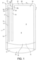
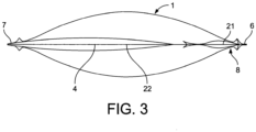
- Pouch 1 shown in Figs. 1 to 3 contains a drink 2, and is provided with a straw 3 within the pouch accessible to allow a user to draw drink from the pouch.
- the pouch defines a top edge 4, a bottom portion 5, and respective side edges 6 and 7 which interconnect the top edge 4 and the bottom portion 5.
- a corner portion 8 is defined between the top edge 4 and side edge 6 for a purpose to be explained below.
- the pouch 1 forms a closed cavity 9 containing drink 2.
- the cavity 9 is defined by the top edge 4, the bottom portion 5, and the side edges 6 and 7. It is formed by two walls made of a heat bondable pliant packaging material to form a front face 10 and a rear face 11 for the cavity 9.
- Suitable such packaging materials both transparent and opaque are well known in the packaging industries and readily available commercially. They are commonly formed in a laminate form to achieve a desired mix of strength, reliability, sealability and shelf-life. It will readily be understood that front 10 and rear 11 faces could just as well be formed by a single continuous wall folded over at side edge 7.
- the front 10 and rear 11 faces are connected along the top edge 4 by a heat seal 12.
- the front 10 and rear 11 faces are connected via a gusset portion 13 of conventional form for drinks pouches to provide the bottom portion 5.
- the gusset may be omitted, the front 10 and rear 11 faces simply being heat sealed together along a bottom edge.
- Heat seal 14 connecting the front and rear faces and running from the top edge 4 to the bottom portion 5.
- a further heat seal 15 connecting the front 10 and rear 11 faces extends from the top edge generally in a direction towards the bottom portion 5 parallel to and spaced from the heat seal 15. It will be seen that heat seal 15 has the effect of dividing the interior of the cavity 9 into major 16 and minor 17 portions. As the heat seal 15 terminates short of the bottom portion, the major 16 and minor 17 portions of cavity 9 remain interconnected so that drink may continue to flow between them.
- the minor portion 17 lies between the heat seals 14 and 15, and defines a space in which straw 3 is located.
- the heat seal 15 does not need to be continuous. If formed with gaps (not shown) interrupting it, drink may flow through the gaps.
- Corner portion 8 is openable along a line of weakness 18 formed in the pouch and extending generally parallel to the top edge 4 from a notch 19 cut into the heat seal 14 to and ending at the heat seal 15.
- the top edge need not be straight, as here, but could be curved in a simple or complex manner. In that case, line of weakness 18 will be generally parallel to the bottom portion 5.
- the line of weakness 18 may be formed both in the respective external faces of the front face 10 and in the rear face 11 of the pouch generally parallel to the top edge 4 (or to the bottom portion if the top edge is not straight) from the first heat seal 14 to and ending at the second heat seal 15, the line of weakness being formed as dotted or dashed lines 18 laser etched into the exterior surfaces of the front and rear faces. This allows the corner portion 8 to be removed as a whole from the remainder of the pouch by tearing along the laser etched lines either from side edge 7 to the cut 20 or from the cut 20 to the side edge 7. Removal of corner portion 8 exposes an end of the straw 3.
- heat seal 12 defining the top edge 4 is interrupted by a cut 20 at heat seal 15 to form a minor heat seal portion 21 extending from heat seal 14 to heat seal 15 and a major heat seal portion 22 separated from the minor heat seal portion 21 by cut 20 and extending from heat seal 15 to side edge 7.
- the heat seal 15 is bifurcated at its end adjacent the top edge to form one branch 15a extending to minor heat seal portion 21 in the corner portion 8 and a second branch 15b extending to the remainder of heat seal 12 in major heat seal portion 22, the cut 20 extending between the two branches.
- a notch 23 similar to notch 19 is cut into the edge of branch 15a at the bottom of cut 20.
- corner portion 8 is removable from the remainder of the pouch 1 by tearing along the line of weakness 18 from side edge 6 to the cut.
- the major advantage of the described construction is that the line of tear is well defined, and the risk of any tear continuing beyond heat seal 15 is greatly reduced. A user will readily locate the straw 3 and be able to draw drink from the cavity 9 without significant risk of spillage.
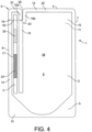
- Fig. 4 this figure shows a front elevational view similar to that of Fig. 1 , for a second embodiment of pouch, using like reference numerals for like parts where appropriate.
- the straw is fixed in position within the minor portion 17 of cavity 9 by a portion 24 intermediate its ends being bonded to an interior surface of the cavity 9 which may be a surface of the laminate form front face 10 or of laminate form rear face 11, or of both.
- the bonded portion 24 may be continuous or formed as several discrete portions.
- the straw also includes a longitudinally expandable portion 25 positioned between the intermediate position 24 and the top edge 4.
- the expandable portion is suitably formed as a concertina section. It will be understood that an expandable portion 25, preferably a concertina section could be employed without the straw necessarily being bonded to one or both internal surfaces of the pouch walls.
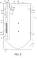
- Fig. 5 shows a similar front elevational view of another embodiment, again with like reference numerals being employed for like parts where appropriate.
- the line of weakness 18 is defined by an elongate tear strip 26, suitably formed of a flat polymer strip whose material is more resistant to tearing than the remaining material of the film, and is incorporated into that material to extend along the line of weakness 18 at least from a position at or adjacent the first heat seal 14 to a position at or adjacent to the second heat seal 15, the tear strip 26 having a graspable free distal end portion 27 extending out of the remaining material of the pouch, whereby the corner portion can be opened by pulling the free distal end portion 27 to tear the remaining material of the pouch along the line of weakness 18.
- the tear strip 26 may be incorporated into the film during its formation as a laminate of different layers between such layers. Rather than being formed as a flat polymer strip, tear strip 26 may be string-like, being of woven or twisted thread form.
- the tear strip 26 extends only from first heat seal 14 to the second heat seal 15 on one face of the pouch along the line of weakness 18, and exits the remaining material of the pouch at or adjacent the second heat seal 15 to provide said distal end portion 27. Pulling on the distal end portion 27, in a direction from right to left in the Figure, will have the effect of tearing the pouch along the line of weakness 18 on only one face. The end result leaves the corner portion 8 open so that the straw 3 can be located to allow a user to drink from the pouch via the straw, but with the corner portion not fully removed from the pouch.
- the tear strip 26 extends from a position at or adjacent the second heat seal 15 on one of the front face and the rear face to a position at or adjacent the first heat seal 14, and then to a position at or adjacent the second heat seal 15 on the other face of the pouch, and exits the remaining material of the pouch on this other face at or adjacent the second heat seal 15 to provide the distal end portion 27.
- pulling on the distal end portion may have the effect of removing the corner portion entirely.
- the notches 19 and 20 at the ends of the line of weakness 18, as described and illustrated in earlier described embodiments will assist in terminating the torn portion, and in preventing the tear running into the remainder of the pouch with a risk of spillage, especially when the pliant material from which the pouch is formed is relatively weak. Where such material is more resistant to tearing, although necessarily still less resistant to tearing than the tear strip 26 in the present disclosure, the ends of the strip may define end points for the resultant tear.
- the major advantage of the described construction is that the line of weakness is well defined, and the risk of any tear continuing beyond heat seal 15 defining the boundary of corner portion 8 is greatly reduced.
- the extent of the tear may be limited in other ways.
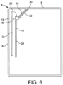
- Figs. 6 and 7 respectively show a somewhat schematic front elevational view of another embodiment of drinks pouch in the fully sealed condition and with the corner portion removed.
- Like reference numerals are employed for like parts.
- Main portion 28 terminates at its upper end in an enlarged abutment 29 connecting the front and rear walls.
- a cut 30 extends from the abutment to the top edge 4 at an angle, sealed on either side by secondary seals 31 and 32.
- Line of weakness 18 extends from side edge 6 at notch 19 to the abutment 29 which serves as an anchor to terminate a tear along the line of weakness.
- the corner portion 8 may be detachable as a whole from the remainder of the pouch or be left to hang down from abutment 29 allowing access to straw 3 without the corner portion getting in the way.
- FIG. 8 shows another arrangement in which the line of weakness is terminated at an abutment 29 at the upper end of second seal 15.
- this embodiment features a fold line 33. Having made a tear from notch 19 on side edge 6 along the line of weakness 18 to terminate at abutment 29, the partially detached corner portion 8 can simply be folded out of the way along line 33.
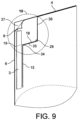
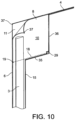
- Fig. 9 and the enlarged corner view of Fig. 10 illustrate a further possibility featuring a peel off opening of the corner portion.
- like reference numerals are employed for like parts.
- the heat seals in all other portions of the pouch are durable, in this embodiment the strength of the heat seals in the corner portion 8 are significantly weaker than elsewhere on the pouch, as explained below.
- the main portion of second heat seal 15 has an upper end 34 at the edge of the corner portion 8 immediately adjacent to line of weakness 18, then extends along a line 35 alongside the line of weakness to terminate at an abutment 29 connecting the front and rear walls of the pouch.
- the line of weakness 18 extends from notch 19 at side edge 6 to terminate at abutment 29.
- a secondary heat seal 36 extends from abutment 29 to top edge 4.
- Secondary heat seal 36 may be parallel to the first heat seal 14 and to the second heat seal 15, may extend at an angle from abutment 29 to top edge 4 similar to secondary seals 31 and 32 in Figs. 6 and 7 , or may extend along a curve.
- the portions of heat seal 12 along the top edge 4 from secondary heat seal 36 to corner 37 of corner portion 8 and of first heat seal 14 along the side edge 4 from notch 19 to corner 37 of corner portion 8 have significantly less strength that the remaining heat seals.
- the front wall 10 is readily separable from the rear wall 11 in corner portion 8 by peeling them apart from the corner 37 as schematically illustrated in Fig. 10 .
- the front wall 10 in corner portion 8 is torn along line 18 from notch 19 to abutment 29, which serves as an anchor to terminate the tear.
- the resultant flap of front wall 10 remains attached to the remainder of front wall 10 along the line of secondary heat seal 36, but can readily be folded back to allow access to the straw 3.
- the straw 3 is fixed internally of the pouch to one or both of the front and back walls, but has an extendable portion (not illustrated), and, even more so, a concertina section allowing it both to be extended and bent, a user can easily drink from the pouch using the straw without the remaining rear wall in the corner portion getting in their way.
Landscapes
- Engineering & Computer Science (AREA)
- Mechanical Engineering (AREA)
- Bag Frames (AREA)
- Packages (AREA)
Claims (10)
- Ein vollständig versiegelter Beutel (1), der ein Getränk (2) enthält und mit einem Strohhalm (3) im Beutel versehen ist, der zugänglich ist, damit ein Benutzer das Getränk aus dem Beutel entnehmen kann; wobei der Beutel einen oberen Abschnitt (4), einen unteren Abschnitt (5) und jeweilige Seitenkanten (6, 7), die den oberen Abschnitt und den unteren Abschnitt verbinden, sowie einen Eckabschnitt (8) definiert, der zwischen dem oberen Abschnitt (4) und und eine Seitenkante (6), wobei der Eckabschnitt von einem Benutzer geöffnet werden kann, um an den Strohhalm zu gelangen; wobei der Beutel einen geschlossenen Hohlraum (9) bildet, der das Getränk enthält, wobei der Hohlraum durch den oberen Abschnitt (4), den unteren Abschnitt (5) und die Seitenränder (6, 7) sowie durch mindestens eine Wand, die eine Vorderseite definiert, definiert wird eine Fläche (10) und eine Rückseite (11) für den Hohlraum, wobei die Vorder- und Rückseite im oberen Abschnitt miteinander verbunden sind und die Vorder- und Rückseite auf der anderen Seite miteinander verbunden sind oder entlang dieser Seite verbunden sind Kanten (7), wobei die Vorder- und Rückseite optional über einen Zwickel (13) verbunden sind, um den Bodenabschnitt bereitzustellen, und wobei die eine Seitenkante (6) durch eine erste Heißsiegelung (14) gebildet wird, die die Vorder- und Rückseite verbindet Gesichter; und eine zweite Heißsiegelung (15), die die Vorder- und Rückseite verbindet und sich unvollständig vom oberen Teil zum unteren Teil erstreckt und innerhalb der ersten Heißsiegelung beabstandet ist, wobei die zweite Heißsiegelung das Innere des Hohlraums (9) teilt in große (16) und kleinere (17) Teile, die so miteinander verbunden sind, dass das Getränk zwischen ihnen fließen kann, wobei der kleinere Teil zwischen der ersten und der zweiten Heißsiegelung liegt und der Strohhalm innerhalb des kleinen Teils liegt; wobei der Beutel dadurch gekennzeichnet ist, dass der Eckabschnitt (8) entlang einer Schwächungslinie (18) geöffnet werden kann, die in dem Beutel ausgebildet ist und sich von der ersten Heißsiegelung aus parallel zum oberen Abschnitt (4) und/oder dem unteren Abschnitt (5) erstreckt (14) zur zweiten Heißsiegelung (15) und endet dort, wobei die zweite Heißsiegelung als Abschluss für einen Riss entlang der Schwächungslinie dient.
- Beutel nach Anspruch 1, weiter dadurch gekennzeichnet, dass der obere Teil (4) eine Oberkante aufweist, die durch eine dritte Heißsiegelung (12) definiert ist, die durch einen Schnitt (20) an der zweiten Heißsiegelung (15) unterbrochen ist und diese teilt Oberkante (4) in einen kleineren Heißsiegelabschnitt (21), der sich von der ersten Heißsiegelung (14) zur zweiten Heißsiegelung (15) erstreckt, und einen großen Heißsiegelabschnitt (22), der von dem kleinen Heißsiegelabschnitt getrennt ist und sich von diesem erstreckt wobei die zweite Heißsiegelung (15) mit der anderen (7) der Seitenkanten verbunden ist und die Schwächungslinie (18) sich von der einen Seitenkante (6) bis zum Schnitt (20) erstreckt, wodurch der Eckabschnitt durch Aufreißen geöffnet werden kann entlang der Schwächungslinie (18) von der einen Seitenkante (6) zum Schnitt (20) und dadurch, dass die zweite Heißsiegelung (15) an ihrem Ende neben der Oberkante gegabelt ist, um einen ersten Zweig (15a) zu bilden sich bis zum kleineren Heißsiegelabschnitt (21) im Eckabschnitt erstreckt und einen zweiten Zweig (15b), der sich bis zum großen Heißsiegelabschnitt (22) erstreckt, wobei sich der Schnitt (20) zwischen den beiden Zweigen erstreckt, wodurch der Eckabschnitt geöffnet werden kann Reißen entlang der Schwächungslinie (18) von der einen Seitenkante (6) zum ersten Zweig (15a) im Schnitt (20).
- Beutel nach Anspruch 1, weiter dadurch gekennzeichnet, dass der obere Teil (4) eine Oberkante aufweist, die durch eine dritte Heißsiegelung definiert ist, die sich von der einen (6) zur anderen (7) der Seitenkanten erstreckt, der zweiten Heißsiegelung Die Dichtung (15) endet kurz vor der Oberkante an einem vergrößerten Widerlager (29), das die Vorder- (10) und die Rückseite (11) verbindet, und die Schwächungslinie (18) erstreckt sich von der einen Seitenkante (6) und endet bei wobei das Widerlager (29) eine Verankerung für die Schwächungslinie bildet, wobei der Eckabschnitt durch Aufreißen entlang der Schwächungslinie von der einen Seitenkante zum Widerlager geöffnet werden kann und optional der obere Abschnitt (4) mit einer Falte versehen ist Linie (33), die sich von der Anlage bis zur Oberkante erstreckt, wobei der Eckabschnitt nach dem Aufreißen entlang der Schwächungslinie entlang der Faltlinie am Rest des Beutels befestigt bleibt, beim Abreißen jedoch entlang der Faltlinie weggefaltet werden kann Ein Benutzer greift auf den Strohhalm zu, um aus dem Beutel zu trinken.
- Beutel nach einem der vorhergehenden Ansprüche, weiter dadurch gekennzeichnet, dass der größere (16) und der kleinere (17) Teil des Inneren des Hohlraums dadurch miteinander verbunden sind, dass die zweite Heißsiegelung (15) kurz vor dem Boden endet Abschnitt, der den Durchgang zwischen dem Haupt- und dem Nebenabschnitt des Hohlraums ermöglicht, und/oder dadurch, dass die zweite Heißsiegelung (15) durch Lücken unterbrochen ist, die den Durchgang zwischen dem Haupt- und dem Nebenabschnitt des Hohlraums ermöglichen.
- Beutel nach einem der vorhergehenden Ansprüche, weiter dadurch gekennzeichnet, dass der Strohhalm (3) an der mindestens einen Wand befestigt ist, wodurch der Strohhalm in seiner Position innerhalb des Beutels zumindest so lange fixiert ist, bis er von einem Benutzer nach dem Öffnen des Eckabschnitts gefunden wird.
- Beutel nach einem der vorhergehenden Ansprüche, weiter dadurch gekennzeichnet, dass die Schwächungslinie (18) sowohl in der Vorderseite (10) als auch in der Rückseite (11) ausgebildet ist und sich von der ersten Heißsiegelung (14) bis dorthin erstreckt und endet an der zweiten Heißsiegelung (15), wobei die Schwächungslinie (18) als gepunktete oder gestrichelte Linien ausgebildet ist, die per Laser in die Außenflächen der Vorder- und Rückseite geätzt sind.
- Beutel nach Anspruch 5, dadurch gekennzeichnet, dass der Beutel aus einem durch Wärme verklebbaren, biegsamen Verpackungsmaterial in Laminatform besteht und der Strohhalm an einer Stelle (24) zwischen den Enden des Strohhalms mit einer Oberfläche desselben verbunden ist mindestens eine Wand im Inneren des Beutels wird durch die Laminatform definiert.
- Beutel nach Anspruch 7, weiter dadurch gekennzeichnet, dass der Strohhalm einen in Längsrichtung expandierbaren Abschnitt aufweist, der zwischen der Zwischenposition und der Oberkante positioniert ist, wobei der Strohhalm über die Oberkante hinaus verlängert werden kann, indem der expandierbare Abschnitt nach dem Öffnen der Ecke erweitert wird.
- Ein Beutel (1), der ein Getränk (2) enthält und mit einem Strohhalm (3) innerhalb des Beutels versehen ist, der zugänglich ist, damit ein Benutzer Getränk aus dem Beutel ziehen kann; wobei der Beutel einen oberen Rand (4), einen unteren Abschnitt (5) und jeweilige Seitenränder (6, 7), die den oberen Rand (4) und den unteren Abschnitt (5) verbinden, sowie einen dazwischen definierten Eckabschnitt (8) definiert die Oberkante und eine der Seitenkanten (6), wobei der Eckabschnitt von einem Benutzer geöffnet werden kann, um an den Strohhalm zu gelangen; wobei der Beutel einen geschlossenen Hohlraum (9) bildet, der das Getränk enthält, wobei der Hohlraum durch den oberen Rand (4), den unteren Teil (5) und die Seitenränder (6, 7) sowie durch mindestens eine Wand, die eine Vorderseite definiert, definiert wird Fläche (10) und eine Rückseite (11) für den Hohlraum, wobei die Vorder- und Rückseite entlang der Oberkante (4) verbunden sind und die Vorder- und Rückseite aneinander anliegen oder entlang der anderen Seite (7) verbunden sind der Seitenkanten, wobei die Vorder- und Rückseite optional über einen Zwickel (13) verbunden sind, um den Bodenabschnitt (5) bereitzustellen, und wobei die eine Seitenkante (6) durch eine erste Heißsiegelung (14) gebildet wird, die diese verbindet Vorder- und Rückseite; eine zweite Heißsiegelung (15), die die Vorder- und Rückseite verbindet und sich im Allgemeinen in Richtung des Bodenabschnitts (5) parallel und mit Abstand zur ersten Siegelung (14) erstreckt, wobei die zweite Siegelung (15) den Innenraum teilt Hohlraum in größere (16) und kleinere (17) Teile, die miteinander verbunden sind, so dass das Getränk zwischen ihnen fließen kann, wobei der kleinere Teil zwischen der ersten und der zweiten Dichtung liegt und der Strohhalm innerhalb des kleinen Teils liegt; wobei der Beutel dadurch gekennzeichnet ist, dass sich die zweite Heißsiegelung von einem vergrößerten Widerlager (29), das die Vorder- (10) und die Rückseite (11) an einer Stelle kurz vor der Oberkante (4) verbindet, zum Bodenteil erstreckt; und dadurch, dass in dem Beutel eine Schwächungslinie (18) gebildet wird, die sich parallel zum Bodenabschnitt (5) von der ersten Heißsiegelung (14) bis zum Anschlag (29) erstreckt und an diesem endet, der einen Anker zum Beenden des Risses bildet entlang der Schwächungslinie, wobei der Eckabschnitt (8) durch Aufreißen entlang der Schwächungslinie von der einen Seitenkante bis zum Widerlager geöffnet werden kann.
- Beutel nach Anspruch 9, weiter dadurch gekennzeichnet, dass sich eine Faltlinie (33) vom Anschlag (29) bis zum oberen Rand (4) erstreckt, wodurch der Eckabschnitt (8) am Rest des Beutels entlang dieser befestigt bleibt Die Faltlinie wird nach dem Aufreißen entlang der Schwächungslinie (18) aufgerissen, sie kann jedoch entlang der Faltlinie weggefaltet werden, wenn ein Benutzer auf den Strohhalm zugreift, um aus dem Beutel zu trinken.
Applications Claiming Priority (6)
| Application Number | Priority Date | Filing Date | Title |
|---|---|---|---|
| GBGB1620689.8A GB201620689D0 (en) | 2016-12-05 | 2016-12-05 | Drinks pouch |
| GBGB1710293.0A GB201710293D0 (en) | 2017-06-28 | 2017-06-28 | Drinks pouch |
| GBGB1710298.9A GB201710298D0 (en) | 2017-06-28 | 2017-06-28 | Drinks pouch |
| GBGB1710296.3A GB201710296D0 (en) | 2017-06-28 | 2017-06-28 | Drinks pouch |
| GBGB1710300.3A GB201710300D0 (en) | 2017-06-28 | 2017-06-28 | Drinks pouch |
| PCT/GB2017/000173 WO2018104692A1 (en) | 2016-12-05 | 2017-12-05 | Drinks pouch |
Publications (4)
| Publication Number | Publication Date |
|---|---|
| EP3548397A1 EP3548397A1 (de) | 2019-10-09 |
| EP3548397C0 EP3548397C0 (de) | 2024-01-03 |
| EP3548397B1 true EP3548397B1 (de) | 2024-01-03 |
| EP3548397B8 EP3548397B8 (de) | 2024-02-14 |
Family
ID=60765988
Family Applications (1)
| Application Number | Title | Priority Date | Filing Date |
|---|---|---|---|
| EP17817816.6A Active EP3548397B8 (de) | 2016-12-05 | 2017-12-05 | Getränkebeutel |
Country Status (6)
| Country | Link |
|---|---|
| US (1) | US11548712B2 (de) |
| EP (1) | EP3548397B8 (de) |
| ES (1) | ES2975142T3 (de) |
| GB (1) | GB2559462B (de) |
| IL (1) | IL267119B2 (de) |
| WO (1) | WO2018104692A1 (de) |
Families Citing this family (6)
| Publication number | Priority date | Publication date | Assignee | Title |
|---|---|---|---|---|
| GB2559462B (en) | 2016-12-05 | 2022-01-12 | Handipak Holdings Ltd | Drinks pouch |
| US12291387B2 (en) | 2016-12-05 | 2025-05-06 | Handipak Holdings Ltd | Drinks pouch |
| ES2926039T3 (es) * | 2018-02-26 | 2022-10-21 | Handipak Holdings Ltd | Bolsa para bebidas |
| US12202664B2 (en) * | 2022-02-21 | 2025-01-21 | Party Paccs, Inc. | Beverage container |
| US12497227B2 (en) * | 2022-06-14 | 2025-12-16 | Gabriel William Adler Schwartz | Container for consumable substances with integrated utensil |
| KR102645146B1 (ko) * | 2023-04-19 | 2024-03-08 | (주)제이비 바이오 | 개봉이 편리하고 액상 음용이 용이한 포장 파우치 |
Citations (8)
| Publication number | Priority date | Publication date | Assignee | Title |
|---|---|---|---|---|
| US3144976A (en) * | 1961-09-18 | 1964-08-18 | Continental Can Co | Liquid filled pouch with straw |
| DE7409493U (de) * | 1974-03-19 | 1974-06-20 | Abova Gmbh | Getränkepackung aus einem randverschweißten Schlauchbeutel |
| JPH08337255A (ja) * | 1995-06-13 | 1996-12-24 | Fuji Seal Co Ltd | ストロー入り飲料用容器 |
| MC2488A1 (fr) * | 1999-04-01 | 1999-11-22 | Pascal Beveraggi | Emballage ou récipient en matière souple pour produits liquides ou semi-liquides intégrant un systéme de consommation dudit liquide |
| US6293394B1 (en) * | 1998-10-27 | 2001-09-25 | Alusuisse Technology & Management, Ltd | Pouch-shaped form of packaging |
| EP1223114A1 (de) * | 2001-01-10 | 2002-07-17 | Danisco Flexible Schüpbach AG | Leicht zu öffnender Folienbeutel, insbesondere für Getränke |
| KR20030020688A (ko) * | 2001-09-04 | 2003-03-10 | 주식회사 코리아팩 | 빨대가 내장된 스탠딩 용기 |
| EP1291295A1 (de) * | 2000-06-02 | 2003-03-12 | Kabushiki Kaisha Hosokawa Yoko | Getränkebehälter |
Family Cites Families (24)
| Publication number | Priority date | Publication date | Assignee | Title |
|---|---|---|---|---|
| US2992118A (en) | 1958-01-20 | 1961-07-11 | Daline Gordon | Liquid container with built-in drinking straw |
| GB980859A (en) * | 1960-04-14 | 1965-01-20 | Robinson Waxed Paper Co Ltd | Pouches for containing liquid |
| US3663239A (en) | 1969-04-07 | 1972-05-16 | Nabisco Inc | Toaster packages having four spouts |
| US3815810A (en) | 1972-07-07 | 1974-06-11 | L Wellman | Opening and re-sealing device for bag containers |
| US4119128A (en) | 1977-02-18 | 1978-10-10 | Marilyn Bishop | Tamperproof sterile port cover and method of making same |
| JPS5780437U (de) | 1980-11-05 | 1982-05-18 | ||
| DE3520451A1 (de) * | 1985-06-07 | 1986-12-11 | Beinio, Brigitte, 4194 Huisberden | Verfahren und vorrichtung zur herstellung von jeweils eine fluessigkeit und ein entnahmeroehrchen, z.b. einen trinkhalm enthaltenden folienbehaeltern |
| FR2714030B1 (fr) | 1993-12-16 | 1996-02-02 | Socoplan Sa | Conteneur pour produit liquide ou pulvérulent à ouverture intégrée. |
| CA2196108A1 (en) | 1997-01-28 | 1998-07-28 | Claire C. Sigouin | Liquid pouch with internal straw restraining passage |
| EP1043246A1 (de) | 1999-04-01 | 2000-10-11 | Pascal Beveraggi | Flexibler Beutel für eine Getränk, Verfahren und Vorrichtung zum Herstellen eines solchen Behälters |
| EP1223144A1 (de) * | 1999-06-28 | 2002-07-17 | Astaris Llc | Gemischte Natriumkaliumpolyphosphaten enthaltendes Getränk |
| DE50013265D1 (de) | 2000-03-21 | 2006-09-14 | Alcan Tech & Man Ag | Verpackung mit Aufreissverschluss |
| MXPA02010973A (es) | 2000-05-08 | 2003-03-27 | Jung Min Lee | Un conjunto surtidor para recipiente de liquido de pelicula delgada. |
| CA2387692C (en) | 2002-05-28 | 2006-07-11 | Urban Pouch-Pack Ltd. | Flexible stand-up liquid pouch with internalized straw |
| EP1976770A1 (de) | 2006-01-27 | 2008-10-08 | The Procter and Gamble Company | Verpackungsbeutel mit tropfauslauf |
| KR20070041693A (ko) | 2007-03-05 | 2007-04-19 | 박영복 | 빨대가 내장된 파우치 |
| DE102009041251A1 (de) | 2009-09-11 | 2011-03-24 | Huhtamaki Ronsberg, Zweigniederlassung Der Huhtamaki Deutschland Gmbh & Co. Kg | Aufreißbeutel |
| KR20110037186A (ko) * | 2009-10-06 | 2011-04-13 | 송하영 | 빨대 내장형 스탠딩 용기 |
| US8740458B2 (en) | 2010-05-25 | 2014-06-03 | Frito-Lay North America, Inc. | Easy open bag |
| US9475622B2 (en) | 2013-08-17 | 2016-10-25 | Westrock Slatersville, Llc | Tamper evident pouch and dispensing fitment |
| US9187225B2 (en) * | 2013-09-27 | 2015-11-17 | Barton Group, Inc. | Flexible container with integral extended internal dispensing tube in a stand-up configuration |
| GB201501819D0 (en) | 2015-02-04 | 2015-03-18 | Discovery Flexibles Ltd | Pouch for liquids and method for making the same |
| EP3162731B1 (de) | 2015-10-30 | 2018-10-03 | Ecolean AB | Beutelartige verpackung und zugehöriges verfahren zur anpassung solch einr verpackung |
| GB2559462B (en) | 2016-12-05 | 2022-01-12 | Handipak Holdings Ltd | Drinks pouch |
-
2017
- 2017-12-05 GB GB1720237.5A patent/GB2559462B/en active Active
- 2017-12-05 WO PCT/GB2017/000173 patent/WO2018104692A1/en not_active Ceased
- 2017-12-05 EP EP17817816.6A patent/EP3548397B8/de active Active
- 2017-12-05 US US16/466,684 patent/US11548712B2/en active Active
- 2017-12-05 IL IL267119A patent/IL267119B2/en unknown
- 2017-12-05 ES ES17817816T patent/ES2975142T3/es active Active
Patent Citations (8)
| Publication number | Priority date | Publication date | Assignee | Title |
|---|---|---|---|---|
| US3144976A (en) * | 1961-09-18 | 1964-08-18 | Continental Can Co | Liquid filled pouch with straw |
| DE7409493U (de) * | 1974-03-19 | 1974-06-20 | Abova Gmbh | Getränkepackung aus einem randverschweißten Schlauchbeutel |
| JPH08337255A (ja) * | 1995-06-13 | 1996-12-24 | Fuji Seal Co Ltd | ストロー入り飲料用容器 |
| US6293394B1 (en) * | 1998-10-27 | 2001-09-25 | Alusuisse Technology & Management, Ltd | Pouch-shaped form of packaging |
| MC2488A1 (fr) * | 1999-04-01 | 1999-11-22 | Pascal Beveraggi | Emballage ou récipient en matière souple pour produits liquides ou semi-liquides intégrant un systéme de consommation dudit liquide |
| EP1291295A1 (de) * | 2000-06-02 | 2003-03-12 | Kabushiki Kaisha Hosokawa Yoko | Getränkebehälter |
| EP1223114A1 (de) * | 2001-01-10 | 2002-07-17 | Danisco Flexible Schüpbach AG | Leicht zu öffnender Folienbeutel, insbesondere für Getränke |
| KR20030020688A (ko) * | 2001-09-04 | 2003-03-10 | 주식회사 코리아팩 | 빨대가 내장된 스탠딩 용기 |
Also Published As
| Publication number | Publication date |
|---|---|
| GB2559462B (en) | 2022-01-12 |
| IL267119A (en) | 2019-08-29 |
| GB2559462A (en) | 2018-08-08 |
| ES2975142T3 (es) | 2024-07-03 |
| GB201720237D0 (en) | 2018-01-17 |
| EP3548397A1 (de) | 2019-10-09 |
| US20190337701A1 (en) | 2019-11-07 |
| US11548712B2 (en) | 2023-01-10 |
| CA3046047A1 (en) | 2018-06-14 |
| IL267119B2 (en) | 2024-03-01 |
| EP3548397C0 (de) | 2024-01-03 |
| EP3548397B8 (de) | 2024-02-14 |
| WO2018104692A1 (en) | 2018-06-14 |
| IL267119B1 (en) | 2023-11-01 |
Similar Documents
| Publication | Publication Date | Title |
|---|---|---|
| EP3548397B1 (de) | Getränkebeutel | |
| US20250229967A1 (en) | Drinks pouch | |
| CA1284301C (en) | Packing container provided with a reclosable opening arrangement | |
| JP7448316B2 (ja) | リサイクリング可能なバッグ | |
| JPH02219744A (ja) | 包装容器の開孔装置 | |
| CN108349637B (zh) | 袋式包装物以及用于适配此类包装物的相关联方法 | |
| WO2005102863A1 (en) | An improved sachet pouch | |
| EP3759033B1 (de) | Getränkebeutel | |
| US7364065B2 (en) | Flexible closure for a container | |
| CA3046047C (en) | Drinks pouch | |
| EP3386883B1 (de) | Lebensmittelverpackung mit wiederverschliessbarer öffnung und verfahren zum öffnen, entnehmen eines lebensmittelprodukts und wiederverschliessen einer wiederverschliessbaren lebensmittelverpackung | |
| JP4042489B2 (ja) | 密封袋 | |
| EP0471274B1 (de) | Verpackungsbehälter mit einer streifenförmigen Öffnungsvorrichtung | |
| EP3219641A1 (de) | Vorrichtung mit wiederversiegelbarer öffnung und verpackung mit solch einer öffnungsvorrichtung | |
| NL9301164A (nl) | Houder voor een giet- of strooibaar produkt, en daarvoor bestemd afdekmateriaal. | |
| US20060237521A1 (en) | Container for a liquid | |
| HK40017694A (en) | Drinks pouch | |
| JP2008050048A (ja) | 捻り開封袋 | |
| EP2776336A1 (de) | Behälter für lebensmittelprodukte | |
| EP2583905A1 (de) | Behälter | |
| JP2019189263A (ja) | 詰替え用包装袋 | |
| EP3017710A1 (de) | Beutel mit integrierter Klebelasche | |
| MX2007014737A (es) | Bolsa tubular comprendiendo una tapa y una lengueta de asir. | |
| AU2004201210A1 (en) | A package and method for manufacturing a package | |
| JP2011020738A (ja) | 即席食品用容器 |
Legal Events
| Date | Code | Title | Description |
|---|---|---|---|
| STAA | Information on the status of an ep patent application or granted ep patent |
Free format text: STATUS: UNKNOWN |
|
| STAA | Information on the status of an ep patent application or granted ep patent |
Free format text: STATUS: THE INTERNATIONAL PUBLICATION HAS BEEN MADE |
|
| PUAI | Public reference made under article 153(3) epc to a published international application that has entered the european phase |
Free format text: ORIGINAL CODE: 0009012 |
|
| STAA | Information on the status of an ep patent application or granted ep patent |
Free format text: STATUS: REQUEST FOR EXAMINATION WAS MADE |
|
| 17P | Request for examination filed |
Effective date: 20190619 |
|
| AK | Designated contracting states |
Kind code of ref document: A1 Designated state(s): AL AT BE BG CH CY CZ DE DK EE ES FI FR GB GR HR HU IE IS IT LI LT LU LV MC MK MT NL NO PL PT RO RS SE SI SK SM TR |
|
| AX | Request for extension of the european patent |
Extension state: BA ME |
|
| DAV | Request for validation of the european patent (deleted) | ||
| DAX | Request for extension of the european patent (deleted) | ||
| STAA | Information on the status of an ep patent application or granted ep patent |
Free format text: STATUS: EXAMINATION IS IN PROGRESS |
|
| 17Q | First examination report despatched |
Effective date: 20200706 |
|
| GRAP | Despatch of communication of intention to grant a patent |
Free format text: ORIGINAL CODE: EPIDOSNIGR1 |
|
| STAA | Information on the status of an ep patent application or granted ep patent |
Free format text: STATUS: GRANT OF PATENT IS INTENDED |
|
| INTG | Intention to grant announced |
Effective date: 20230818 |
|
| GRAS | Grant fee paid |
Free format text: ORIGINAL CODE: EPIDOSNIGR3 |
|
| GRAA | (expected) grant |
Free format text: ORIGINAL CODE: 0009210 |
|
| STAA | Information on the status of an ep patent application or granted ep patent |
Free format text: STATUS: THE PATENT HAS BEEN GRANTED |
|
| AK | Designated contracting states |
Kind code of ref document: B1 Designated state(s): AL AT BE BG CH CY CZ DE DK EE ES FI FR GB GR HR HU IE IS IT LI LT LU LV MC MK MT NL NO PL PT RO RS SE SI SK SM TR |
|
| RAP3 | Party data changed (applicant data changed or rights of an application transferred) |
Owner name: HANDIPAK HOLDINGS LTD |
|
| REG | Reference to a national code |
Ref country code: GB Ref legal event code: FG4D |
|
| REG | Reference to a national code |
Ref country code: DE Ref legal event code: R096 Ref document number: 602017078163 Country of ref document: DE |
|
| REG | Reference to a national code |
Ref country code: CH Ref legal event code: EP |
|
| RBV | Designated contracting states (corrected) |
Designated state(s): AL AT BE BG CH CY CZ DE DK EE ES FI FR GR HR HU IE IS IT LI LT LU LV MC MK MT NL NO PL PT RO RS SE SI SK SM TR |
|
| REG | Reference to a national code |
Ref country code: IE Ref legal event code: FG4D Ref country code: CH Ref legal event code: PK Free format text: BERICHTIGUNG B8 |
|
| U01 | Request for unitary effect filed |
Effective date: 20240201 |
|
| U07 | Unitary effect registered |
Designated state(s): AT BE BG DE DK EE FI FR IT LT LU LV MT NL PT SE SI Effective date: 20240212 |
|
| PG25 | Lapsed in a contracting state [announced via postgrant information from national office to epo] |
Ref country code: IS Free format text: LAPSE BECAUSE OF FAILURE TO SUBMIT A TRANSLATION OF THE DESCRIPTION OR TO PAY THE FEE WITHIN THE PRESCRIBED TIME-LIMIT Effective date: 20240503 |
|
| REG | Reference to a national code |
Ref country code: ES Ref legal event code: FG2A Ref document number: 2975142 Country of ref document: ES Kind code of ref document: T3 Effective date: 20240703 |
|
| PG25 | Lapsed in a contracting state [announced via postgrant information from national office to epo] |
Ref country code: GR Free format text: LAPSE BECAUSE OF FAILURE TO SUBMIT A TRANSLATION OF THE DESCRIPTION OR TO PAY THE FEE WITHIN THE PRESCRIBED TIME-LIMIT Effective date: 20240404 |
|
| PG25 | Lapsed in a contracting state [announced via postgrant information from national office to epo] |
Ref country code: HR Free format text: LAPSE BECAUSE OF FAILURE TO SUBMIT A TRANSLATION OF THE DESCRIPTION OR TO PAY THE FEE WITHIN THE PRESCRIBED TIME-LIMIT Effective date: 20240103 Ref country code: RS Free format text: LAPSE BECAUSE OF FAILURE TO SUBMIT A TRANSLATION OF THE DESCRIPTION OR TO PAY THE FEE WITHIN THE PRESCRIBED TIME-LIMIT Effective date: 20240403 |
|
| PG25 | Lapsed in a contracting state [announced via postgrant information from national office to epo] |
Ref country code: RS Free format text: LAPSE BECAUSE OF FAILURE TO SUBMIT A TRANSLATION OF THE DESCRIPTION OR TO PAY THE FEE WITHIN THE PRESCRIBED TIME-LIMIT Effective date: 20240403 Ref country code: NO Free format text: LAPSE BECAUSE OF FAILURE TO SUBMIT A TRANSLATION OF THE DESCRIPTION OR TO PAY THE FEE WITHIN THE PRESCRIBED TIME-LIMIT Effective date: 20240403 Ref country code: IS Free format text: LAPSE BECAUSE OF FAILURE TO SUBMIT A TRANSLATION OF THE DESCRIPTION OR TO PAY THE FEE WITHIN THE PRESCRIBED TIME-LIMIT Effective date: 20240503 Ref country code: HR Free format text: LAPSE BECAUSE OF FAILURE TO SUBMIT A TRANSLATION OF THE DESCRIPTION OR TO PAY THE FEE WITHIN THE PRESCRIBED TIME-LIMIT Effective date: 20240103 Ref country code: GR Free format text: LAPSE BECAUSE OF FAILURE TO SUBMIT A TRANSLATION OF THE DESCRIPTION OR TO PAY THE FEE WITHIN THE PRESCRIBED TIME-LIMIT Effective date: 20240404 |
|
| PG25 | Lapsed in a contracting state [announced via postgrant information from national office to epo] |
Ref country code: PL Free format text: LAPSE BECAUSE OF FAILURE TO SUBMIT A TRANSLATION OF THE DESCRIPTION OR TO PAY THE FEE WITHIN THE PRESCRIBED TIME-LIMIT Effective date: 20240103 |
|
| PG25 | Lapsed in a contracting state [announced via postgrant information from national office to epo] |
Ref country code: PL Free format text: LAPSE BECAUSE OF FAILURE TO SUBMIT A TRANSLATION OF THE DESCRIPTION OR TO PAY THE FEE WITHIN THE PRESCRIBED TIME-LIMIT Effective date: 20240103 |
|
| REG | Reference to a national code |
Ref country code: DE Ref legal event code: R097 Ref document number: 602017078163 Country of ref document: DE |
|
| PG25 | Lapsed in a contracting state [announced via postgrant information from national office to epo] |
Ref country code: SM Free format text: LAPSE BECAUSE OF FAILURE TO SUBMIT A TRANSLATION OF THE DESCRIPTION OR TO PAY THE FEE WITHIN THE PRESCRIBED TIME-LIMIT Effective date: 20240103 |
|
| PG25 | Lapsed in a contracting state [announced via postgrant information from national office to epo] |
Ref country code: CZ Free format text: LAPSE BECAUSE OF FAILURE TO SUBMIT A TRANSLATION OF THE DESCRIPTION OR TO PAY THE FEE WITHIN THE PRESCRIBED TIME-LIMIT Effective date: 20240103 |
|
| PG25 | Lapsed in a contracting state [announced via postgrant information from national office to epo] |
Ref country code: SK Free format text: LAPSE BECAUSE OF FAILURE TO SUBMIT A TRANSLATION OF THE DESCRIPTION OR TO PAY THE FEE WITHIN THE PRESCRIBED TIME-LIMIT Effective date: 20240103 |
|
| PG25 | Lapsed in a contracting state [announced via postgrant information from national office to epo] |
Ref country code: SM Free format text: LAPSE BECAUSE OF FAILURE TO SUBMIT A TRANSLATION OF THE DESCRIPTION OR TO PAY THE FEE WITHIN THE PRESCRIBED TIME-LIMIT Effective date: 20240103 Ref country code: SK Free format text: LAPSE BECAUSE OF FAILURE TO SUBMIT A TRANSLATION OF THE DESCRIPTION OR TO PAY THE FEE WITHIN THE PRESCRIBED TIME-LIMIT Effective date: 20240103 Ref country code: RO Free format text: LAPSE BECAUSE OF FAILURE TO SUBMIT A TRANSLATION OF THE DESCRIPTION OR TO PAY THE FEE WITHIN THE PRESCRIBED TIME-LIMIT Effective date: 20240103 Ref country code: CZ Free format text: LAPSE BECAUSE OF FAILURE TO SUBMIT A TRANSLATION OF THE DESCRIPTION OR TO PAY THE FEE WITHIN THE PRESCRIBED TIME-LIMIT Effective date: 20240103 |
|
| PLBE | No opposition filed within time limit |
Free format text: ORIGINAL CODE: 0009261 |
|
| STAA | Information on the status of an ep patent application or granted ep patent |
Free format text: STATUS: NO OPPOSITION FILED WITHIN TIME LIMIT |
|
| U20 | Renewal fee for the european patent with unitary effect paid |
Year of fee payment: 8 Effective date: 20241017 |
|
| 26N | No opposition filed |
Effective date: 20241007 |
|
| PGFP | Annual fee paid to national office [announced via postgrant information from national office to epo] |
Ref country code: ES Payment date: 20250102 Year of fee payment: 8 |
|
| PG25 | Lapsed in a contracting state [announced via postgrant information from national office to epo] |
Ref country code: MC Free format text: LAPSE BECAUSE OF FAILURE TO SUBMIT A TRANSLATION OF THE DESCRIPTION OR TO PAY THE FEE WITHIN THE PRESCRIBED TIME-LIMIT Effective date: 20240103 |
|
| REG | Reference to a national code |
Ref country code: CH Ref legal event code: PL |
|
| PG25 | Lapsed in a contracting state [announced via postgrant information from national office to epo] |
Ref country code: CH Free format text: LAPSE BECAUSE OF NON-PAYMENT OF DUE FEES Effective date: 20241231 |
|
| PG25 | Lapsed in a contracting state [announced via postgrant information from national office to epo] |
Ref country code: IE Free format text: LAPSE BECAUSE OF NON-PAYMENT OF DUE FEES Effective date: 20241205 |
|
| U20 | Renewal fee for the european patent with unitary effect paid |
Year of fee payment: 9 Effective date: 20251016 |