EP3548325B1 - Synchronisierte übertragung - Google Patents
Synchronisierte übertragung Download PDFInfo
- Publication number
- EP3548325B1 EP3548325B1 EP17821486.2A EP17821486A EP3548325B1 EP 3548325 B1 EP3548325 B1 EP 3548325B1 EP 17821486 A EP17821486 A EP 17821486A EP 3548325 B1 EP3548325 B1 EP 3548325B1
- Authority
- EP
- European Patent Office
- Prior art keywords
- transmission
- cam
- synchronizer
- actuation
- wheel
- Prior art date
- Legal status (The legal status is an assumption and is not a legal conclusion. Google has not performed a legal analysis and makes no representation as to the accuracy of the status listed.)
- Active
Links
Images


Classifications
-
- B—PERFORMING OPERATIONS; TRANSPORTING
- B60—VEHICLES IN GENERAL
- B60K—ARRANGEMENT OR MOUNTING OF PROPULSION UNITS OR OF TRANSMISSIONS IN VEHICLES; ARRANGEMENT OR MOUNTING OF PLURAL DIVERSE PRIME-MOVERS IN VEHICLES; AUXILIARY DRIVES FOR VEHICLES; INSTRUMENTATION OR DASHBOARDS FOR VEHICLES; ARRANGEMENTS IN CONNECTION WITH COOLING, AIR INTAKE, GAS EXHAUST OR FUEL SUPPLY OF PROPULSION UNITS IN VEHICLES
- B60K5/00—Arrangement or mounting of internal-combustion or jet-propulsion units
- B60K5/04—Arrangement or mounting of internal-combustion or jet-propulsion units with the engine main axis, e.g. crankshaft axis, transversely to the longitudinal centre line of the vehicle
-
- F—MECHANICAL ENGINEERING; LIGHTING; HEATING; WEAPONS; BLASTING
- F16—ENGINEERING ELEMENTS AND UNITS; GENERAL MEASURES FOR PRODUCING AND MAINTAINING EFFECTIVE FUNCTIONING OF MACHINES OR INSTALLATIONS; THERMAL INSULATION IN GENERAL
- F16H—GEARING
- F16H61/00—Control functions within control units of change-speed- or reversing-gearings for conveying rotary motion ; Control of exclusively fluid gearing, friction gearing, gearings with endless flexible members or other particular types of gearing
- F16H61/26—Generation or transmission of movements for final actuating mechanisms
- F16H61/28—Generation or transmission of movements for final actuating mechanisms with at least one movement of the final actuating mechanism being caused by a non-mechanical force, e.g. power-assisted
-
- B—PERFORMING OPERATIONS; TRANSPORTING
- B60—VEHICLES IN GENERAL
- B60K—ARRANGEMENT OR MOUNTING OF PROPULSION UNITS OR OF TRANSMISSIONS IN VEHICLES; ARRANGEMENT OR MOUNTING OF PLURAL DIVERSE PRIME-MOVERS IN VEHICLES; AUXILIARY DRIVES FOR VEHICLES; INSTRUMENTATION OR DASHBOARDS FOR VEHICLES; ARRANGEMENTS IN CONNECTION WITH COOLING, AIR INTAKE, GAS EXHAUST OR FUEL SUPPLY OF PROPULSION UNITS IN VEHICLES
- B60K17/00—Arrangement or mounting of transmissions in vehicles
- B60K17/04—Arrangement or mounting of transmissions in vehicles characterised by arrangement, location or kind of gearing
- B60K17/043—Transmission unit disposed in on near the vehicle wheel, or between the differential gear unit and the wheel
-
- B—PERFORMING OPERATIONS; TRANSPORTING
- B62—LAND VEHICLES FOR TRAVELLING OTHERWISE THAN ON RAILS
- B62M—RIDER PROPULSION OF WHEELED VEHICLES OR SLEDGES; POWERED PROPULSION OF SLEDGES OR SINGLE-TRACK CYCLES; TRANSMISSIONS SPECIALLY ADAPTED FOR SUCH VEHICLES
- B62M7/00—Motorcycles characterised by position of motor or engine
- B62M7/02—Motorcycles characterised by position of motor or engine with engine between front and rear wheels
- B62M7/06—Motorcycles characterised by position of motor or engine with engine between front and rear wheels directly under the saddle or seat
-
- B—PERFORMING OPERATIONS; TRANSPORTING
- B62—LAND VEHICLES FOR TRAVELLING OTHERWISE THAN ON RAILS
- B62M—RIDER PROPULSION OF WHEELED VEHICLES OR SLEDGES; POWERED PROPULSION OF SLEDGES OR SINGLE-TRACK CYCLES; TRANSMISSIONS SPECIALLY ADAPTED FOR SUCH VEHICLES
- B62M9/00—Transmissions characterised by use of an endless chain, belt, or the like
- B62M9/04—Transmissions characterised by use of an endless chain, belt, or the like of changeable ratio
-
- F—MECHANICAL ENGINEERING; LIGHTING; HEATING; WEAPONS; BLASTING
- F16—ENGINEERING ELEMENTS AND UNITS; GENERAL MEASURES FOR PRODUCING AND MAINTAINING EFFECTIVE FUNCTIONING OF MACHINES OR INSTALLATIONS; THERMAL INSULATION IN GENERAL
- F16D—COUPLINGS FOR TRANSMITTING ROTATION; CLUTCHES; BRAKES
- F16D28/00—Electrically-actuated clutches
-
- F—MECHANICAL ENGINEERING; LIGHTING; HEATING; WEAPONS; BLASTING
- F16—ENGINEERING ELEMENTS AND UNITS; GENERAL MEASURES FOR PRODUCING AND MAINTAINING EFFECTIVE FUNCTIONING OF MACHINES OR INSTALLATIONS; THERMAL INSULATION IN GENERAL
- F16H—GEARING
- F16H63/00—Control outputs from the control unit to change-speed- or reversing-gearings for conveying rotary motion or to other devices than the final output mechanism
- F16H63/02—Final output mechanisms therefor; Actuating means for the final output mechanisms
- F16H63/08—Multiple final output mechanisms being moved by a single common final actuating mechanism
- F16H63/16—Multiple final output mechanisms being moved by a single common final actuating mechanism the final output mechanisms being successively actuated by progressive movement of the final actuating mechanism
- F16H63/18—Multiple final output mechanisms being moved by a single common final actuating mechanism the final output mechanisms being successively actuated by progressive movement of the final actuating mechanism the final actuating mechanism comprising cams
-
- F—MECHANICAL ENGINEERING; LIGHTING; HEATING; WEAPONS; BLASTING
- F16—ENGINEERING ELEMENTS AND UNITS; GENERAL MEASURES FOR PRODUCING AND MAINTAINING EFFECTIVE FUNCTIONING OF MACHINES OR INSTALLATIONS; THERMAL INSULATION IN GENERAL
- F16H—GEARING
- F16H7/00—Gearings for conveying rotary motion by endless flexible members
- F16H7/02—Gearings for conveying rotary motion by endless flexible members with belts; with V-belts
-
- B—PERFORMING OPERATIONS; TRANSPORTING
- B60—VEHICLES IN GENERAL
- B60Y—INDEXING SCHEME RELATING TO ASPECTS CROSS-CUTTING VEHICLE TECHNOLOGY
- B60Y2200/00—Type of vehicle
- B60Y2200/10—Road Vehicles
- B60Y2200/12—Motorcycles, Trikes; Quads; Scooters
-
- F—MECHANICAL ENGINEERING; LIGHTING; HEATING; WEAPONS; BLASTING
- F16—ENGINEERING ELEMENTS AND UNITS; GENERAL MEASURES FOR PRODUCING AND MAINTAINING EFFECTIVE FUNCTIONING OF MACHINES OR INSTALLATIONS; THERMAL INSULATION IN GENERAL
- F16D—COUPLINGS FOR TRANSMITTING ROTATION; CLUTCHES; BRAKES
- F16D23/00—Details of mechanically-actuated clutches not specific for one distinct type
- F16D23/12—Mechanical clutch-actuating mechanisms arranged outside the clutch as such
- F16D2023/123—Clutch actuation by cams, ramps or ball-screw mechanisms
Definitions
- the present invention relates to a transmission which can be used in a vehicle and in particular a motorcycle, wherein the crankshaft actuated by the engine and the driven shaft, connected to a rear wheel, are substantially parallel therebetween and both parallel to the hub axis of the rear wheel which is kinematically connected to the crankshaft in a synchronous way, for example by means of pulleys assembled on the respective shafts and at least a belt therebetween.
- Patent document GB2526902A discloses an example of gearbox provided with a shifting movement which is controlled by interlocking interaction of a cam with a rotatable coulisse.
- Patent document JP 2007 177908 A discloses another transmission provided with a cam actuator.
- two synchronizers can be provided: a first synchronizer placed at the front of the crankshaft and a second synchronizer placed at the front of a driven shaft connected kinematically to said rear wheel.
- the synchronizers have to be actuated based upon a predetermined sequence thereto the different transmission speeds correspond.
- the synchronizers have to be driven with an absolute respect for said sequence and actuation time requested for each speedchange, in repeatable and continuing way.
- the technical problem underlying the present invention is to provide a synchronized transmission allowing to obviate the drawback mentioned with reference to the known art.
- the main advantage of the above defined transmission consists in guaranteeing the implementation of each synchronizer according to a prefixed scheme.
- a motorcycle, and in particular a scooter is designated as a whole with 100.
- the invention relates to the field of the saddle vehicles, or vehicles which are driven astride, in general, having two, three or four wheels, with particular reference to the scooters having a propulsion unit arranged in a position below a saddle 101, inside a chassis 102 which herein is represented laterally, extending from a front wheel 103, driven by a handlebar 104 to a driving rear wheel 105.
- the propulsion unit 106 ( figure 6 ) or, in short, the engine is of the type having one or more cylinders arranged in a tilted position approximatively on the median plane of the vehicle which corresponds to the rotation plane of the two wheels during the rectilinear forward motion.
- the engine 106 has an engine block 107 in one single piece which receives, in the present embodiment, a cylinder 108 and a related (not visible) piston.
- the piston acting in said cylinder 108 is connected to a crankshaft 2 positioned transversally and perpendicularly to said median plane.
- a transmission device 1 is provided or, more shortly, a transmission of the motion from the crankshaft to the hub of the rear wheel 105.
- the transmission 1 has a container 109 which receives inside thereof the transmission elements which will be described in greater detail hereinafter.
- the container 109 is connected to the engine block 107 by creating a tunnel-like casing including the crankshaft 2 and all transmission elements connected thereto.
- the container 109 is closed, on the exposed side of the motorcycle 100, by a cover 110 of the transmission 1, which extends substantially from the engine 106 to the hub shaft of the driving wheel 105.
- the cover 110 is fastened to the container 109 by means of suitable bolts 111. Openings, slots, air intakes could be provided to access and/or cool down the transmission elements through said cover 110.
- the cover 110 is rested upon a fixing edge 112 of the container 109, provided with fixing seats 113 for said bolts 111 and with additional front connection seat 114, with a hinge connection of axis A to allow the engine block 107 and the transmission 1 to swing, and rear connection seat 115, connected to a rear suspension 116, to connect the casing 109 and the whole transmission 1 to the frame of the vehicle 100.
- Such transmission is of multiple speed type and of synchronous type 1, and it is arranged for connecting the crankshaft 2, which receives the motion from moving one or more pistons, to the hub shaft, by considering that these two shafts are parallel therebetween and placed at a prefixed distance.
- the hub shaft at a distal end thereof, is provided with a pinion 5 for connecting to the rear wheel 105.
- a multiple gearbox without the casing 109 and the cover 110 in particular a transmission with four-speed gearbox, is designated as a whole with 1. It is of the type suitable to be assembled on a motorcycle as transmission element which actuates a driving wheel of the motorcycle 100, in particular a scooter, that is the rear wheel thereof 105.
- crankshaft 2 which is made to rotate by the engine, thereof the piston rod 30 is represented, and a first driven shaft, that is the primary shaft 3, and a secondary shaft, which can be connected directly to the wheel or which transmits the rotation, as in the present embodiment, to a hub shaft 5 which is connected to the driving wheel of the vehicle.
- this transmission element has the purpose of transferring the motion from an engine, having a crankshaft transversal to the motorcycle, to a wheel having an axis transversal to the vehicle, too.
- the hub shaft 5 could be constituted by the same secondary shaft, provided that one renounces to the above mentioned reduction ratio on the hub and providing to invert the rotation direction of the crankshaft 2.
- the crankshaft 2 and the primary shaft 3 are substantially parallel and they are connected by transmission elements which allow the motion transmission according to different speed ratios.
- Such transmission elements include a first group of toothed pulleys assembled on the crankshaft 2, a second group of toothed pulleys assembled at the primary shaft 3, and a pair of transmission belts extending from the first to the second group of pulleys.
- any flexible annular element is meant apt to transmit the motion between two pulleys offset therebetween, in particular with axes parallel therebetween.
- the transmission belts then include any kind of belts or chains, the pulleys in case could be toothed to implement a synchronous connection.
- the transmission belts advantageously are synchronous transmission belts; under synchronous belt a belt, usually a toothed belt or a roller chain, is meant which transmits the motion from a wheel or toothed pulley to another wheel or toothed pulley with a transmission ratio which is determined by the ratio between the diameters of the wheels, without it is subjected to clutch or sliding losses.
- the herein described transmission is of the synchronous or almost synchronous type, and it uses a pair of pulleys connected kinematically by a belt, preferably a toothed belt on toothed pulleys or a high performance belt, for example of the Stretch Fit ® type or the like.
- the above-mentioned pulleys are toothed pulleys, connected by toothed belts, preferably of the type made of rubber.
- a main clutch 8 is assembled which, in the present example, is of centrifugal type, well known in the art.
- this kind of clutch allows the motion transmission from the crankshaft 2 to the cascaded transmission elements, and it engages automatically at a rotation regime comprised in a prefixed range, for example between 1000 and 2000 revolutions per minute. At a lower rotation regime, the clutch 8 is not engaged and the engine is idle, whereas the driving wheel is not stressed.
- this type of clutch can be replaced by a manual coupling clutch which is perfectly equivalent, or by a clutch actuated by a servo-mechanism.
- a first pulley 9 and a second pulley 10 are keyed in cascade to said clutch 8. They are respectively connected, by means of a first synchronous belt 11, to a third pulley 12 and, by means of a second synchronous belt 13, to a fourth pulley 14.
- first synchronizer 16 for synchronizing the second belt 13, that is the connection between second and fourth pulley 10, 14, whereas at the front of the primary shaft 3 there is a second synchronizer 17 which synchronizes the toothed wheels keyed on such primary shaft 3.
- a first and a second toothed wheel are keyed on the primary shaft 3 which are engaged, respectively with a third toothed wheel and with a fourth toothed wheel, both keyed on the secondary shaft.
- the third toothed wheel 20, in this embodiment, is assembled on a second free wheel.
- the system is requested to pass from the first to the second speed and, even in this case, the transmission uses the first synchronous belt 11.
- the second actuated synchronizer 17, arranged on the primary shaft 3, is activated, and so it intervenes by synchronizing a pair of toothed wheels assigned to the transmission of the second and of the fourth speed.
- the system is requested to pass from the second to the third speed and, in this case, the transmission has to use the second synchronous belt 13.
- the first synchronizer 16 placed onto the crankshaft 2 is activated, by implementing the synchronization of the second pulley 10 of the third and of fourth speed.
- the second synchronous belt 13, now placed in motion transmits the motion to the primary shaft 3 of the gearbox.
- the primary shaft 3 would have two different speeds set by the transmission, however this is avoided by the presence of a free wheel which allows to disengage the third pulley 13 related to the first and second speed.
- the second synchronizer 20 on the primary shaft 3 has to be deactivated, so as to cease the synchronization of the ratio of toothed wheels of second and fourth speed. Therefore, the motion reaches the primary shaft 3 through the pair of pulleys related to the third and fourth speed, and the primary shaft 3 rotates with the speed set by the third speed.
- the synchronizer has to be deactivated independently from the rotation speed reached by the respective primary shaft 3, and this makes that it has to be of actuated type, that is of the type which is actuated or deactivated after an actuation determined by a system decision and not by simply reaching a rotation regime.
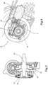
- the synchronizer comprises a supporting plate 21 which has a substantially flared shape, to define a space contained therein; then it has a concavity faced in opposite direction with respect to the transmission elements to be actuated.
- a more external one thereat the plate 21 comprises a wide central opening, and a more internal one having a central hole, thereat it is constrained to transmission elements, in particular to the carter of a gearbox.
- actuation axis constituted by a shaft 53, having a proximal actuation end 22 inserted internally in the central hole of the plate 21.
- the rotating shaft 53 extends from the supporting plate 21 in the remaining portion of the transmission elements which will be now described; the axial translation thereof determines the synchronization of a transmission element.
- the synchronizer comprises a bell-like spring 23 which is substantially shaped like a cone, implemented by a metal sheaf wherein through slots are made allowing to deform the spring 23 according to an axial direction.
- the cam follower 26 is substantially shaped like a disc and the cam profile thereof is formed on the disc face directed outwards, defined on a peripheral circumference arc of the cam 26 and formed by a raised rib.
- the disc of the cam follower 26 forms a plane perpendicular to the synchronization axis, and the cam profile thereof projects perpendicularly from said plane, in axial direction.
- a corresponding cam 29 is associated to the above-mentioned cam follower 26, having a hole wherein an actuation spindle 30 is inserted with a plug connection allowing the rotation of the cam 29 by rotating said spindle 30, the axis thereof coincides with the axis of the actuation shaft 53.
- cam follower 26 has a recess faced towards the actuation spindle 30 which constitutes a seat thereof for the distal end thereof.
- the cam 29 comprises a ring apt to couple with said cam follower 26, on the exposed face thereof a second cam profile is formed which projects axially and which is intended to couple with the cam profile of the cam follower 26. On this regard, it will include a raised cam surface, a lowered cam surface and related tilted connections.
- the above-described synchronizers 16, 17 have an actuation of axial type, that is they are actuated by the translation of an element in the direction of the rotation axis of the rotating shaft thereon the synchronization takes place.
- Each synchronizer 16, 17 comprises a respective rotating cam actuator having a cam 29 apt to be rotated by an actuation spindle 30 of the cam 29 which determines the translation of a cam follower 26 which in turn interferes with the actuation end 22 of the respective synchronizer.
- the actuation spindle 30 comprises a control wheel 36 which is useful to rotate the cam 29 with respect to the cam follower 26, thus determining the translation of the cam 26 and, consequently, of the actuation end 22 and of the shaft 53.
- the first synchronizer 16 has a first control wheel 36 which, as it will appear better hereinafter, is a toothed wheel which is dragged in rotation by an electric motor.
- a half-rotation of the cam 29 determines the translation, in one direction or in the other one, of the cam follower 26, of the bearing 25 and of the bell-like spring 23, and then of the actuation end 22.
- a first and a second actuation pulley 37, 38, respectively, is provided on the actuation spindle 30 of each synchronizer 16, 17, keyed in particular on the distal end of the spindle projecting outside the synchronizer.
- the two actuation pulleys 37, 38 are made synchronous by an actuation belt 39, in particular of filiform type, inserted in the peripheral guides of the actuation pulleys 37, 38.
- this synchrony will be so as to determine, in sequence, the activation of the second synchronizer (second speed), followed by the de-activation thereof and by the simultaneous activation of the first synchronizer (third speed), in turn followed by the simultaneous activation of both synchronizers (fourth speed), starting from both de-activated synchronizers (first speed).
- the first actuating pulley 37 connected to an actuation spindle 30 of the cam 29 which is rotated by the control wheel 26, and the second actuating pulley 38, connected to the other actuation spindle 30 of the second synchronizer 17, are connected by a belt so that the simultaneous rotation thereof is caused by the rotation of said control wheel 36, each speed corresponding to an angular position of said first and second actuating pulleys 37, 38.
- This sequence will be controlled by the rotation of the control wheel 36, and in particular a step of said sequence will correspond to each rotation angle of 90°.
- control wheel 36 is a toothed wheel which is actuated in rotation by means of an electric motor 40 equipped with a toothed shaft 41 engaged in said toothed wheel 36.
- this electric motor will be of the type with rotating shaft, which conveniently will be of the screw type.
- the screw shaft 41 is included in a casing 42 which guarantees the position thereof, and it is connected by means of a plug connection to the rotor of the electric motor 40, the whole being connected to the transmission carter and electrically fed through a control board.
- the electric motor 40, the screw shaft thereof 41 and the toothed control wheel 36 are arranged at the first synchronizer, that is the one arranged at the crankshaft 2 of the transmission 1, whereas the second synchronizer 17 is actuated in cascade through the actuating pulleys, but it is meant that this scheme could be in case overturned without leaving the protective scope of the present invention as defined by the scope of the appended claims.
- the electric motor could be selected of the most convenient type for this application. It could be driven by a board which replies either to a pre-set operation logic in a wholly automatic gearbox or to a control given by the vehicle's driver.
- the electric motor could be of axial type, so as to control in axial translation a control spindle which, in this case, could be a rack.
Landscapes
- Engineering & Computer Science (AREA)
- Mechanical Engineering (AREA)
- General Engineering & Computer Science (AREA)
- Chemical & Material Sciences (AREA)
- Combustion & Propulsion (AREA)
- Transportation (AREA)
- Physics & Mathematics (AREA)
- Electromagnetism (AREA)
- Arrangement Of Transmissions (AREA)
- Transmissions By Endless Flexible Members (AREA)
- Gear-Shifting Mechanisms (AREA)
- Devices For Conveying Motion By Means Of Endless Flexible Members (AREA)
- Control Of Transmission Device (AREA)
- Mechanical Operated Clutches (AREA)
- Preparation Of Compounds By Using Micro-Organisms (AREA)
Claims (9)
- Mehrgängige Übertragung (1) eines Motorrads, bei der eine vom Motor betätigte Kurbelwelle und eine mit einem Hinterrad verbundene Abtriebswelle im Wesentlichen parallel zueinander verlaufen und miteinander verbunden sind, umfassend eine erste axiale Betätigungssynchronisiereinrichtung (16), die an der Vorderseite der Kurbelwelle (2) angeordnet ist, und eine zweite axiale Betätigungssynchronisiereinrichtung (17), die an der Vorderseite einer mit einem Hinterrad verbundenen Abtriebswelle angeordnet ist, wobei jede Synchronisiereinrichtung (16, 17) einen jeweiligen rotierenden Nockenaktor (26, 29) mit einem Nockenfolger (26) umfasst, der durch eine jeweilige Nockenwelle (30) gedreht werden kann, indem eine Verschiebung des Nockenfolgers (26) verursacht wird, die mit einem Betätigungsende (22) der jeweiligen Synchronisiereinrichtung (16, 17) zusammenwirkt, wobei die Übertragung (1) ferner umfasst:ein gezahntes Steuerrad (36), das auf einer der Nockenwellen (30) verkeilt ist und mittels eines Elektromotors (40) in Drehung versetzt wird, der mit einer gezahnten Welle (41) ausgestattet ist, die in das gezahnte Steuerrad (36) eingreift; und wobei die Übertragung dadurch gekennzeichnet ist, dass sie ferner umfasst:eine erste Betätigungsscheibe (37), die mit einer dem Steuerrad (36) entsprechenden Nockenwelle (30) verbunden ist, und eine zweite Betätigungsscheibe (38), die mit der anderen Nockenwelle (30) verbunden ist, wobei die Scheiben (37, 38) durch einen Riemen (39) verbunden sind, der ihre gleichzeitige Drehung durch Betätigung des Steuerrads (36) bewirkt, wobei jede Geschwindigkeit einer Winkelstellung der ersten und zweiten Betätigungsscheibe (37, 38) entspricht.
- Synchronisierte Übertragung (1) nach Anspruch 1, wobei jeder rotierende Nockenaktor eine Nocke (29) aufweist, die durch eine Betätigungswelle (30) der Nocke (29) drehbar ist, die die Verschiebung eines Nockenfolgers (26) verursacht, der seinerseits gegen eine Feder (3) in das Betätigungsende (22) der jeweiligen Synchronisiereinrichtung (16, 17) eingreift.
- Synchronisierte Übertragung (1) nach Anspruch 1, wobei zwischen Nockenfolger (26) und Betätigungsende (22) ein Lager (25) vorgesehen ist.
- Synchronisierte Übertragung (1) nach Anspruch 1, wobei die erste und die zweite Betätigungsscheibe (37, 38) am distalen Ende der aus der Synchronisiereinrichtung herausragenden Nockenwelle (30) verkeilt sind.
- Synchronisierte Übertragung (1) nach Anspruch 1, wobei der Betätigungsriemen 39 vom fadenförmigen Typ ist.
- Synchronisierte Übertragung (1) nach Anspruch 1, wobei die Drehung des Steuerrades (36) so angeordnet ist, dass sie nacheinander die Aktivierung der zweiten Synchronisiereinrichtung (zweiter Gang), gefolgt von deren Deaktivierung und der gleichzeitigen Aktivierung der ersten Synchronisiereinrichtung (dritter Gang), gefolgt von der gleichzeitigen Aktivierung beider Synchronisiereinrichtungen (vierter Gang), ausgehend von den beiden deaktivierten Synchronisiereinrichtungen (erster Gang) verursacht.
- Synchronisierte Übertragung (1) nach Anspruch 6, wobei der Ablauf durch die Drehung des Steuerrades (36) gesteuert wird, wobei ein Schritt des Ablaufs jedem Drehwinkel von 90° davon entspricht.
- Synchronisierte Übertragung (1) nach Anspruch 1, wobei der Elektromotor (40) eine rotierende Welle aufweist, die eine Schrauben-Zahnwelle (41) steuert.
- Motorrad (100), umfassend eine Antriebseinheit (106), die in einer Position unterhalb eines Sattels (101) innerhalb eines Fahrgestells (102) angeordnet ist, das sich von einem Vorderrad (103) zu einem hinteren Antriebsrad (105) erstreckt, wobei es zwischen der Antriebseinheit (106) und dem Hinterrad (105) eine Übertragung (1) gemäß einem der vorstehenden Ansprüche umfasst, das in einem Behälter (109) aufgenommen ist, der an einer freiliegenden Seite des Motorrads (100) durch eine Abdeckung (110) verschlossen ist.
Applications Claiming Priority (2)
| Application Number | Priority Date | Filing Date | Title |
|---|---|---|---|
| IT102016000122192A IT201600122192A1 (it) | 2016-12-01 | 2016-12-01 | Trasmissione sincronizzata |
| PCT/EP2017/081012 WO2018100078A1 (en) | 2016-12-01 | 2017-11-30 | Synchronized transmission |
Publications (3)
| Publication Number | Publication Date |
|---|---|
| EP3548325A1 EP3548325A1 (de) | 2019-10-09 |
| EP3548325B1 true EP3548325B1 (de) | 2023-08-16 |
| EP3548325C0 EP3548325C0 (de) | 2023-08-16 |
Family
ID=58994992
Family Applications (1)
| Application Number | Title | Priority Date | Filing Date |
|---|---|---|---|
| EP17821486.2A Active EP3548325B1 (de) | 2016-12-01 | 2017-11-30 | Synchronisierte übertragung |
Country Status (7)
| Country | Link |
|---|---|
| US (1) | US11292328B2 (de) |
| EP (1) | EP3548325B1 (de) |
| JP (1) | JP7044782B2 (de) |
| CN (1) | CN110214093A (de) |
| IT (1) | IT201600122192A1 (de) |
| TW (1) | TWI751238B (de) |
| WO (1) | WO2018100078A1 (de) |
Families Citing this family (1)
| Publication number | Priority date | Publication date | Assignee | Title |
|---|---|---|---|---|
| CZ2019185A3 (cs) * | 2019-03-27 | 2019-12-27 | Dvořák - Svahové Sekačky S.R.O. | Náprava, zejména podvozku univerzálního nosiče |
Family Cites Families (16)
| Publication number | Priority date | Publication date | Assignee | Title |
|---|---|---|---|---|
| JPH05157163A (ja) | 1991-12-03 | 1993-06-22 | Kawasaki Heavy Ind Ltd | 自動車用変速機 |
| JP2002081534A (ja) * | 2000-09-04 | 2002-03-22 | Bando Chem Ind Ltd | 車両用変速制御装置 |
| WO2005008100A1 (ja) * | 2003-07-16 | 2005-01-27 | Yamaha Hatsudoki Kabushiki Kaisha | 鞍乗型車両用エンジン及びそれを備えた鞍乗型車両 |
| JP4405465B2 (ja) * | 2005-12-28 | 2010-01-27 | 本田技研工業株式会社 | ツインクラッチ装置 |
| DE102006055798A1 (de) * | 2006-07-28 | 2008-01-31 | Robert Bosch Gmbh | Kupplungsaktor |
| JP4767149B2 (ja) * | 2006-10-27 | 2011-09-07 | ヤマハ発動機株式会社 | 鞍乗型車両 |
| TR201002817T1 (tr) * | 2007-10-12 | 2010-08-23 | Tvs Motor Company Limited | İki tekerlekli hibrid bir araç için transmisyon sistemi |
| CN201784785U (zh) * | 2010-08-27 | 2011-04-06 | 李智光 | 电动摩托车动力装置 |
| EP2527236B1 (de) * | 2011-05-27 | 2013-07-31 | iwis motorsysteme GmbH & Co. KG | Schaltbare Getriebeanordnung |
| KR101202832B1 (ko) * | 2012-01-27 | 2012-11-21 | 서광모 | 무단변속기가 구비된 전기 차량의 동력전달장치 |
| JP5911782B2 (ja) * | 2012-09-28 | 2016-04-27 | 本田技研工業株式会社 | 鞍乗り型車両の変速装置 |
| FR3008755B1 (fr) * | 2013-07-16 | 2016-11-04 | Renault Sa | Commande mecanique compacte pour double embrayage |
| DE102013021947A1 (de) * | 2013-12-20 | 2015-06-25 | GM Global Technology Operations LLC (n. d. Gesetzen des Staates Delaware) | Schaltgetriebe und Kupplungsbaugruppe dafür |
| DE102014003241A1 (de) * | 2014-03-10 | 2015-09-10 | GM Global Technology Operations LLC (n. d. Ges. d. Staates Delaware) | Schaltgetriebe |
| JP5996701B1 (ja) * | 2015-03-30 | 2016-09-21 | 本田技研工業株式会社 | シンクロ機構付き変速装置 |
| JP6538016B2 (ja) * | 2016-09-30 | 2019-07-03 | 本田技研工業株式会社 | 鞍乗り型車両用内燃機関 |
-
2016
- 2016-12-01 IT IT102016000122192A patent/IT201600122192A1/it unknown
-
2017
- 2017-11-30 US US16/464,891 patent/US11292328B2/en active Active
- 2017-11-30 CN CN201780074668.2A patent/CN110214093A/zh active Pending
- 2017-11-30 EP EP17821486.2A patent/EP3548325B1/de active Active
- 2017-11-30 JP JP2019528793A patent/JP7044782B2/ja active Active
- 2017-11-30 WO PCT/EP2017/081012 patent/WO2018100078A1/en not_active Ceased
- 2017-12-01 TW TW106142188A patent/TWI751238B/zh not_active IP Right Cessation
Also Published As
| Publication number | Publication date |
|---|---|
| US11292328B2 (en) | 2022-04-05 |
| IT201600122192A1 (it) | 2018-06-01 |
| TWI751238B (zh) | 2022-01-01 |
| US20190389295A1 (en) | 2019-12-26 |
| CN110214093A (zh) | 2019-09-06 |
| TW201827730A (zh) | 2018-08-01 |
| JP2020500768A (ja) | 2020-01-16 |
| WO2018100078A1 (en) | 2018-06-07 |
| EP3548325C0 (de) | 2023-08-16 |
| EP3548325A1 (de) | 2019-10-09 |
| JP7044782B2 (ja) | 2022-03-30 |
Similar Documents
| Publication | Publication Date | Title |
|---|---|---|
| EP1956269B1 (de) | Antrieb und im Grätschsitz zu führendes Fahrzeug | |
| US20140349792A1 (en) | Countinuously variable transmission drive pulley | |
| EP3548768B1 (de) | Hochleistungsfähiges synchrongetriebe | |
| CN108603585A (zh) | 具有用于改变换挡曲线的装置的无级变速装置 | |
| EP3548325B1 (de) | Synchronisierte übertragung | |
| EP3548376B1 (de) | Synchronisierte übertragung, insbesondere für motorräder | |
| US20190316659A1 (en) | High performance synchronous transmission | |
| US20180223974A1 (en) | Four-speed motorcycle transmission | |
| EP3332155B1 (de) | Motorradgetriebe mit drei geschwindigkeiten | |
| EP3548776B1 (de) | Hochleistungsfähiges synchrongetriebe | |
| WO2018100151A1 (en) | Axial actuation synchronizer | |
| EP3548778B1 (de) | Hochleistungsfähiges synchrongetriebe | |
| US10995823B2 (en) | Power unit for saddled vehicle | |
| EP3548375B1 (de) | Hochleistungsfähiges synchrongetriebe | |
| IT201600122205A1 (it) | Trasmissione con rilievo del rapporto impiegato |
Legal Events
| Date | Code | Title | Description |
|---|---|---|---|
| STAA | Information on the status of an ep patent application or granted ep patent |
Free format text: STATUS: UNKNOWN |
|
| STAA | Information on the status of an ep patent application or granted ep patent |
Free format text: STATUS: THE INTERNATIONAL PUBLICATION HAS BEEN MADE |
|
| PUAI | Public reference made under article 153(3) epc to a published international application that has entered the european phase |
Free format text: ORIGINAL CODE: 0009012 |
|
| STAA | Information on the status of an ep patent application or granted ep patent |
Free format text: STATUS: REQUEST FOR EXAMINATION WAS MADE |
|
| 17P | Request for examination filed |
Effective date: 20190624 |
|
| AK | Designated contracting states |
Kind code of ref document: A1 Designated state(s): AL AT BE BG CH CY CZ DE DK EE ES FI FR GB GR HR HU IE IS IT LI LT LU LV MC MK MT NL NO PL PT RO RS SE SI SK SM TR |
|
| AX | Request for extension of the european patent |
Extension state: BA ME |
|
| DAV | Request for validation of the european patent (deleted) | ||
| DAX | Request for extension of the european patent (deleted) | ||
| STAA | Information on the status of an ep patent application or granted ep patent |
Free format text: STATUS: EXAMINATION IS IN PROGRESS |
|
| 17Q | First examination report despatched |
Effective date: 20210719 |
|
| GRAP | Despatch of communication of intention to grant a patent |
Free format text: ORIGINAL CODE: EPIDOSNIGR1 |
|
| STAA | Information on the status of an ep patent application or granted ep patent |
Free format text: STATUS: GRANT OF PATENT IS INTENDED |
|
| INTG | Intention to grant announced |
Effective date: 20230310 |
|
| GRAS | Grant fee paid |
Free format text: ORIGINAL CODE: EPIDOSNIGR3 |
|
| GRAA | (expected) grant |
Free format text: ORIGINAL CODE: 0009210 |
|
| STAA | Information on the status of an ep patent application or granted ep patent |
Free format text: STATUS: THE PATENT HAS BEEN GRANTED |
|
| AK | Designated contracting states |
Kind code of ref document: B1 Designated state(s): AL AT BE BG CH CY CZ DE DK EE ES FI FR GB GR HR HU IE IS IT LI LT LU LV MC MK MT NL NO PL PT RO RS SE SI SK SM TR |
|
| REG | Reference to a national code |
Ref country code: GB Ref legal event code: FG4D |
|
| REG | Reference to a national code |
Ref country code: CH Ref legal event code: EP |
|
| REG | Reference to a national code |
Ref country code: DE Ref legal event code: R096 Ref document number: 602017072868 Country of ref document: DE |
|
| REG | Reference to a national code |
Ref country code: IE Ref legal event code: FG4D |
|
| U01 | Request for unitary effect filed |
Effective date: 20230913 |
|
| U07 | Unitary effect registered |
Designated state(s): AT BE BG DE DK EE FI FR IT LT LU LV MT NL PT SE SI Effective date: 20230920 |
|
| U20 | Renewal fee for the european patent with unitary effect paid |
Year of fee payment: 7 Effective date: 20231020 |
|
| PG25 | Lapsed in a contracting state [announced via postgrant information from national office to epo] |
Ref country code: GR Free format text: LAPSE BECAUSE OF FAILURE TO SUBMIT A TRANSLATION OF THE DESCRIPTION OR TO PAY THE FEE WITHIN THE PRESCRIBED TIME-LIMIT Effective date: 20231117 |
|
| PG25 | Lapsed in a contracting state [announced via postgrant information from national office to epo] |
Ref country code: IS Free format text: LAPSE BECAUSE OF FAILURE TO SUBMIT A TRANSLATION OF THE DESCRIPTION OR TO PAY THE FEE WITHIN THE PRESCRIBED TIME-LIMIT Effective date: 20231216 |
|
| PG25 | Lapsed in a contracting state [announced via postgrant information from national office to epo] |
Ref country code: RS Free format text: LAPSE BECAUSE OF FAILURE TO SUBMIT A TRANSLATION OF THE DESCRIPTION OR TO PAY THE FEE WITHIN THE PRESCRIBED TIME-LIMIT Effective date: 20230816 Ref country code: NO Free format text: LAPSE BECAUSE OF FAILURE TO SUBMIT A TRANSLATION OF THE DESCRIPTION OR TO PAY THE FEE WITHIN THE PRESCRIBED TIME-LIMIT Effective date: 20231116 Ref country code: IS Free format text: LAPSE BECAUSE OF FAILURE TO SUBMIT A TRANSLATION OF THE DESCRIPTION OR TO PAY THE FEE WITHIN THE PRESCRIBED TIME-LIMIT Effective date: 20231216 Ref country code: HR Free format text: LAPSE BECAUSE OF FAILURE TO SUBMIT A TRANSLATION OF THE DESCRIPTION OR TO PAY THE FEE WITHIN THE PRESCRIBED TIME-LIMIT Effective date: 20230816 Ref country code: GR Free format text: LAPSE BECAUSE OF FAILURE TO SUBMIT A TRANSLATION OF THE DESCRIPTION OR TO PAY THE FEE WITHIN THE PRESCRIBED TIME-LIMIT Effective date: 20231117 |
|
| PG25 | Lapsed in a contracting state [announced via postgrant information from national office to epo] |
Ref country code: PL Free format text: LAPSE BECAUSE OF FAILURE TO SUBMIT A TRANSLATION OF THE DESCRIPTION OR TO PAY THE FEE WITHIN THE PRESCRIBED TIME-LIMIT Effective date: 20230816 |
|
| PG25 | Lapsed in a contracting state [announced via postgrant information from national office to epo] |
Ref country code: ES Free format text: LAPSE BECAUSE OF FAILURE TO SUBMIT A TRANSLATION OF THE DESCRIPTION OR TO PAY THE FEE WITHIN THE PRESCRIBED TIME-LIMIT Effective date: 20230816 |
|
| PG25 | Lapsed in a contracting state [announced via postgrant information from national office to epo] |
Ref country code: SM Free format text: LAPSE BECAUSE OF FAILURE TO SUBMIT A TRANSLATION OF THE DESCRIPTION OR TO PAY THE FEE WITHIN THE PRESCRIBED TIME-LIMIT Effective date: 20230816 Ref country code: RO Free format text: LAPSE BECAUSE OF FAILURE TO SUBMIT A TRANSLATION OF THE DESCRIPTION OR TO PAY THE FEE WITHIN THE PRESCRIBED TIME-LIMIT Effective date: 20230816 Ref country code: ES Free format text: LAPSE BECAUSE OF FAILURE TO SUBMIT A TRANSLATION OF THE DESCRIPTION OR TO PAY THE FEE WITHIN THE PRESCRIBED TIME-LIMIT Effective date: 20230816 Ref country code: CZ Free format text: LAPSE BECAUSE OF FAILURE TO SUBMIT A TRANSLATION OF THE DESCRIPTION OR TO PAY THE FEE WITHIN THE PRESCRIBED TIME-LIMIT Effective date: 20230816 Ref country code: SK Free format text: LAPSE BECAUSE OF FAILURE TO SUBMIT A TRANSLATION OF THE DESCRIPTION OR TO PAY THE FEE WITHIN THE PRESCRIBED TIME-LIMIT Effective date: 20230816 |
|
| PLBE | No opposition filed within time limit |
Free format text: ORIGINAL CODE: 0009261 |
|
| STAA | Information on the status of an ep patent application or granted ep patent |
Free format text: STATUS: NO OPPOSITION FILED WITHIN TIME LIMIT |
|
| REG | Reference to a national code |
Ref country code: CH Ref legal event code: PL |
|
| PG25 | Lapsed in a contracting state [announced via postgrant information from national office to epo] |
Ref country code: MC Free format text: LAPSE BECAUSE OF FAILURE TO SUBMIT A TRANSLATION OF THE DESCRIPTION OR TO PAY THE FEE WITHIN THE PRESCRIBED TIME-LIMIT Effective date: 20230816 |
|
| PG25 | Lapsed in a contracting state [announced via postgrant information from national office to epo] |
Ref country code: CH Free format text: LAPSE BECAUSE OF NON-PAYMENT OF DUE FEES Effective date: 20231130 |
|
| 26N | No opposition filed |
Effective date: 20240517 |
|
| GBPC | Gb: european patent ceased through non-payment of renewal fee |
Effective date: 20231130 |
|
| PG25 | Lapsed in a contracting state [announced via postgrant information from national office to epo] |
Ref country code: MC Free format text: LAPSE BECAUSE OF FAILURE TO SUBMIT A TRANSLATION OF THE DESCRIPTION OR TO PAY THE FEE WITHIN THE PRESCRIBED TIME-LIMIT Effective date: 20230816 Ref country code: CH Free format text: LAPSE BECAUSE OF NON-PAYMENT OF DUE FEES Effective date: 20231130 |
|
| REG | Reference to a national code |
Ref country code: IE Ref legal event code: MM4A |
|
| PG25 | Lapsed in a contracting state [announced via postgrant information from national office to epo] |
Ref country code: IE Free format text: LAPSE BECAUSE OF NON-PAYMENT OF DUE FEES Effective date: 20231130 |
|
| PG25 | Lapsed in a contracting state [announced via postgrant information from national office to epo] |
Ref country code: GB Free format text: LAPSE BECAUSE OF NON-PAYMENT OF DUE FEES Effective date: 20231130 |
|
| PG25 | Lapsed in a contracting state [announced via postgrant information from national office to epo] |
Ref country code: IE Free format text: LAPSE BECAUSE OF NON-PAYMENT OF DUE FEES Effective date: 20231130 Ref country code: GB Free format text: LAPSE BECAUSE OF NON-PAYMENT OF DUE FEES Effective date: 20231130 |
|
| U20 | Renewal fee for the european patent with unitary effect paid |
Year of fee payment: 8 Effective date: 20241126 |
|
| PG25 | Lapsed in a contracting state [announced via postgrant information from national office to epo] |
Ref country code: CY Free format text: LAPSE BECAUSE OF FAILURE TO SUBMIT A TRANSLATION OF THE DESCRIPTION OR TO PAY THE FEE WITHIN THE PRESCRIBED TIME-LIMIT; INVALID AB INITIO Effective date: 20171130 |
|
| PG25 | Lapsed in a contracting state [announced via postgrant information from national office to epo] |
Ref country code: HU Free format text: LAPSE BECAUSE OF FAILURE TO SUBMIT A TRANSLATION OF THE DESCRIPTION OR TO PAY THE FEE WITHIN THE PRESCRIBED TIME-LIMIT; INVALID AB INITIO Effective date: 20171130 |
|
| PG25 | Lapsed in a contracting state [announced via postgrant information from national office to epo] |
Ref country code: TR Free format text: LAPSE BECAUSE OF FAILURE TO SUBMIT A TRANSLATION OF THE DESCRIPTION OR TO PAY THE FEE WITHIN THE PRESCRIBED TIME-LIMIT Effective date: 20230816 |
|
| U20 | Renewal fee for the european patent with unitary effect paid |
Year of fee payment: 9 Effective date: 20251127 |