EP3548288B1 - Fluidische matrize - Google Patents
Fluidische matrize Download PDFInfo
- Publication number
- EP3548288B1 EP3548288B1 EP17905302.0A EP17905302A EP3548288B1 EP 3548288 B1 EP3548288 B1 EP 3548288B1 EP 17905302 A EP17905302 A EP 17905302A EP 3548288 B1 EP3548288 B1 EP 3548288B1
- Authority
- EP
- European Patent Office
- Prior art keywords
- fluid
- actuators
- fluid actuators
- address
- actuator
- Prior art date
- Legal status (The legal status is an assumption and is not a legal conclusion. Google has not performed a legal analysis and makes no representation as to the accuracy of the status listed.)
- Active
Links
Images



Classifications
-
- B—PERFORMING OPERATIONS; TRANSPORTING
- B41—PRINTING; LINING MACHINES; TYPEWRITERS; STAMPS
- B41J—TYPEWRITERS; SELECTIVE PRINTING MECHANISMS, i.e. MECHANISMS PRINTING OTHERWISE THAN FROM A FORME; CORRECTION OF TYPOGRAPHICAL ERRORS
- B41J2/00—Typewriters or selective printing mechanisms characterised by the printing or marking process for which they are designed
- B41J2/005—Typewriters or selective printing mechanisms characterised by the printing or marking process for which they are designed characterised by bringing liquid or particles selectively into contact with a printing material
- B41J2/01—Ink jet
- B41J2/015—Ink jet characterised by the jet generation process
- B41J2/04—Ink jet characterised by the jet generation process generating single droplets or particles on demand
- B41J2/045—Ink jet characterised by the jet generation process generating single droplets or particles on demand by pressure, e.g. electromechanical transducers
- B41J2/04501—Control methods or devices therefor, e.g. driver circuits, control circuits
- B41J2/04543—Block driving
-
- B—PERFORMING OPERATIONS; TRANSPORTING
- B41—PRINTING; LINING MACHINES; TYPEWRITERS; STAMPS
- B41J—TYPEWRITERS; SELECTIVE PRINTING MECHANISMS, i.e. MECHANISMS PRINTING OTHERWISE THAN FROM A FORME; CORRECTION OF TYPOGRAPHICAL ERRORS
- B41J2/00—Typewriters or selective printing mechanisms characterised by the printing or marking process for which they are designed
- B41J2/005—Typewriters or selective printing mechanisms characterised by the printing or marking process for which they are designed characterised by bringing liquid or particles selectively into contact with a printing material
- B41J2/01—Ink jet
- B41J2/015—Ink jet characterised by the jet generation process
- B41J2/04—Ink jet characterised by the jet generation process generating single droplets or particles on demand
- B41J2/045—Ink jet characterised by the jet generation process generating single droplets or particles on demand by pressure, e.g. electromechanical transducers
- B41J2/04501—Control methods or devices therefor, e.g. driver circuits, control circuits
- B41J2/0452—Control methods or devices therefor, e.g. driver circuits, control circuits reducing demand in current or voltage
-
- B—PERFORMING OPERATIONS; TRANSPORTING
- B41—PRINTING; LINING MACHINES; TYPEWRITERS; STAMPS
- B41J—TYPEWRITERS; SELECTIVE PRINTING MECHANISMS, i.e. MECHANISMS PRINTING OTHERWISE THAN FROM A FORME; CORRECTION OF TYPOGRAPHICAL ERRORS
- B41J2/00—Typewriters or selective printing mechanisms characterised by the printing or marking process for which they are designed
- B41J2/005—Typewriters or selective printing mechanisms characterised by the printing or marking process for which they are designed characterised by bringing liquid or particles selectively into contact with a printing material
- B41J2/01—Ink jet
- B41J2/015—Ink jet characterised by the jet generation process
- B41J2/04—Ink jet characterised by the jet generation process generating single droplets or particles on demand
- B41J2/045—Ink jet characterised by the jet generation process generating single droplets or particles on demand by pressure, e.g. electromechanical transducers
- B41J2/04501—Control methods or devices therefor, e.g. driver circuits, control circuits
- B41J2/0458—Control methods or devices therefor, e.g. driver circuits, control circuits controlling heads based on heating elements forming bubbles
-
- B—PERFORMING OPERATIONS; TRANSPORTING
- B41—PRINTING; LINING MACHINES; TYPEWRITERS; STAMPS
- B41J—TYPEWRITERS; SELECTIVE PRINTING MECHANISMS, i.e. MECHANISMS PRINTING OTHERWISE THAN FROM A FORME; CORRECTION OF TYPOGRAPHICAL ERRORS
- B41J2/00—Typewriters or selective printing mechanisms characterised by the printing or marking process for which they are designed
- B41J2/005—Typewriters or selective printing mechanisms characterised by the printing or marking process for which they are designed characterised by bringing liquid or particles selectively into contact with a printing material
- B41J2/01—Ink jet
- B41J2/015—Ink jet characterised by the jet generation process
- B41J2/04—Ink jet characterised by the jet generation process generating single droplets or particles on demand
- B41J2/045—Ink jet characterised by the jet generation process generating single droplets or particles on demand by pressure, e.g. electromechanical transducers
- B41J2/04501—Control methods or devices therefor, e.g. driver circuits, control circuits
- B41J2/04581—Control methods or devices therefor, e.g. driver circuits, control circuits controlling heads based on piezoelectric elements
-
- B—PERFORMING OPERATIONS; TRANSPORTING
- B41—PRINTING; LINING MACHINES; TYPEWRITERS; STAMPS
- B41J—TYPEWRITERS; SELECTIVE PRINTING MECHANISMS, i.e. MECHANISMS PRINTING OTHERWISE THAN FROM A FORME; CORRECTION OF TYPOGRAPHICAL ERRORS
- B41J2/00—Typewriters or selective printing mechanisms characterised by the printing or marking process for which they are designed
- B41J2/005—Typewriters or selective printing mechanisms characterised by the printing or marking process for which they are designed characterised by bringing liquid or particles selectively into contact with a printing material
- B41J2/01—Ink jet
- B41J2/015—Ink jet characterised by the jet generation process
- B41J2/04—Ink jet characterised by the jet generation process generating single droplets or particles on demand
- B41J2/045—Ink jet characterised by the jet generation process generating single droplets or particles on demand by pressure, e.g. electromechanical transducers
- B41J2/04501—Control methods or devices therefor, e.g. driver circuits, control circuits
- B41J2/04541—Specific driving circuit
-
- B—PERFORMING OPERATIONS; TRANSPORTING
- B41—PRINTING; LINING MACHINES; TYPEWRITERS; STAMPS
- B41J—TYPEWRITERS; SELECTIVE PRINTING MECHANISMS, i.e. MECHANISMS PRINTING OTHERWISE THAN FROM A FORME; CORRECTION OF TYPOGRAPHICAL ERRORS
- B41J2/00—Typewriters or selective printing mechanisms characterised by the printing or marking process for which they are designed
- B41J2/005—Typewriters or selective printing mechanisms characterised by the printing or marking process for which they are designed characterised by bringing liquid or particles selectively into contact with a printing material
- B41J2/01—Ink jet
- B41J2/135—Nozzles
- B41J2/14—Structure thereof only for on-demand ink jet heads
- B41J2002/14467—Multiple feed channels per ink chamber
-
- B—PERFORMING OPERATIONS; TRANSPORTING
- B41—PRINTING; LINING MACHINES; TYPEWRITERS; STAMPS
- B41J—TYPEWRITERS; SELECTIVE PRINTING MECHANISMS, i.e. MECHANISMS PRINTING OTHERWISE THAN FROM A FORME; CORRECTION OF TYPOGRAPHICAL ERRORS
- B41J2/00—Typewriters or selective printing mechanisms characterised by the printing or marking process for which they are designed
- B41J2/005—Typewriters or selective printing mechanisms characterised by the printing or marking process for which they are designed characterised by bringing liquid or particles selectively into contact with a printing material
- B41J2/01—Ink jet
- B41J2/135—Nozzles
- B41J2/14—Structure thereof only for on-demand ink jet heads
- B41J2002/14491—Electrical connection
-
- B—PERFORMING OPERATIONS; TRANSPORTING
- B41—PRINTING; LINING MACHINES; TYPEWRITERS; STAMPS
- B41J—TYPEWRITERS; SELECTIVE PRINTING MECHANISMS, i.e. MECHANISMS PRINTING OTHERWISE THAN FROM A FORME; CORRECTION OF TYPOGRAPHICAL ERRORS
- B41J2202/00—Embodiments of or processes related to ink-jet or thermal heads
- B41J2202/01—Embodiments of or processes related to ink-jet heads
- B41J2202/12—Embodiments of or processes related to ink-jet heads with ink circulating through the whole print head
Definitions
- the invention relates to fluidic dies.
- Fluidic dies may control the movement and ejection of fluid.
- Such fluidic dies may include fluid actuators that may be actuated to cause displacement of fluid.
- Some example fluidic dies may be printheads, where the fluid may correspond to ink.
- WO 2016/068894 A1 describes a printhead assembly, comprising an electrical interface for connection to a printing system and a fluid interface for connection to an ink reservoir that supplies ink, and ink ejection devices with corresponding nozzles, where an array of ink injection devices and their corresponding nozzles may be arranged into primitives. Each nozzle within a primitive may be assigned an address. Ink injection devices and their corresponding nozzles in a particular primitive may have the same or different characteristics, e.g. ink color, drop weight, energy requirements etc.
- WO 2016/089371 A1 describes a printhead assembly including a fluid feed slot, two columns of nozzles and an addressing circuit to receive a nozzle address and an activation mode to activate the nozzles.
- the nozzles are arranged into primitives.
- a singe primitive may be associated with two energy delivery devices.
- the invention is defined by apparatus claim 1 and method claim 10.
- fluidic dies may comprise fluid actuators.
- the fluid actuators may include a piezoelectric membrane based actuator, a thermal resistor based actuator, an electrostatic membrane actuator, a mechanical/impact driven membrane actuator, a magneto-strictive drive actuator, or other such elements that may cause displacement of fluid responsive to electrical actuation.
- Fluidic dies described herein may comprise a plurality of fluid actuators, which may be referred to as an array of fluid actuators.
- an actuation event as used herein, may refer to concurrent actuation of fluid actuators of the fluidic die to thereby cause fluid displacement.
- concurrent actuation of fluid actuators may include slight time delays at and between each of the concurrently actuated individual actuators such that the fluid actuators are not actuated simultaneously, reducing peak voltage demands.
- the array of fluid actuators may be arranged in respective sets of fluid actuators, where each such set of fluid actuators may be referred to as a "primitive” or a "firing primitive.”
- a primitive generally comprises a group or set of fluid actuators that each have a unique actuation address.
- electrical and fluidic constraints of a fluidic die may limit which fluid actuators of each primitive may be actuated concurrently for a given actuation event. Therefore, primitives facilitate addressing and subsequent actuation of fluid ejector subsets that may be concurrently actuated for a given actuation event.
- a number of fluid ejectors corresponding to a respective primitive may be referred to as a size of the primitive.
- a fluidic die comprises four primitives, where each respective primitive comprises eight respective fluid actuators (each eight fluid actuator group having an address 0 to 7), and electrical and fluidic constraints limit actuation to one fluid actuator per primitive, a total of four fluid actuators (one from each primitive) may be concurrently actuated for a given actuation event. For example, for a first actuation event, the respective fluid actuator of each primitive having an address of 0 may be actuated. For a second actuation event, the respective fluid actuator of each primitive having an address of 1 may be actuated. As will be appreciated, the example is provided merely for illustration purposes. Fluidic dies contemplated herein may comprise more or less fluid actuators per primitive and more or less primitives per die.
- the fluid actuators may be concurrently enabled by a single address enabling event caused by electric signals transmitted along a fluid actuator address line.
- an address enabling event may refer to concurrent enablement of fluid actuators of different primitives having a same address to ready such fluid actuators for subsequent actuation in response to receiving other enabling signals.
- actuation of a fluid actuator may occur in response to a fluid actuator receiving at least the address enabling signals transmitted across a fluid actuator address line and primitive enabling signals received across a data or primitive select line.
- a fluid actuator address line may comprise a single electrically conductive line, such as a wire or trace, or a set of electrically conductive lines which cooperate to transmit a set of electrical signals to form the address enabling event.
- a fluid actuator may be disposed in a nozzle, where the nozzle may comprise a fluid chamber and a nozzle orifice in addition to the fluid actuator.
- the fluid actuator may be actuated such that displacement of fluid in the fluid chamber may cause ejection of a fluid drop via the nozzle orifice.
- a fluid actuator disposed in a nozzle may be referred to as a fluid ejector.
- Some example fluidic dies comprise microfluidic channels, Microfluidic channels may be formed by performing etching, microfabrication (e.g., photolithography), micromachining processes, or any combination thereof in a substrate of the fluidic die.
- Some example substrates may include silicon based substrates, glass based substrates, gallium arsenide based substrates, and/or other such suitable types of substrates for microfabricated devices and structures. Accordingly, microfluidic channels, chambers, orifices, and/or other such features may be defined by surfaces fabricated in the substrate of a fluidic die.
- a microfluidic channel may correspond to a channel of sufficiently small size (e.g., of nanometer sized scale, micrometer sized scale, millimeter sized scale, etc.) to facilitate conveyance of small volumes of fluid (e.g., picoliter scale, nanoliter scale, microliter scale, milliliter scale, etc.).
- Example fluidic dies described herein may comprise microfluidic channels in which fluidic actuators may be disposed. In such implementations, actuation of a fluid actuator disposed in a microfluidic channel may generate fluid displacement in the microfluidic channel. Accordingly, a fluid actuator disposed in a microfluidic channel may be referred to as a fluid pump.
- a fluidic die may include a substrate supporting a fluid actuator address line and first and second primitives or sets of fluid actuators connected to the fluid actuator address line.
- the first primitive or set of fluid actuators may include first and second types of fluid actuators having different operating characteristics.
- the second primitive or set of fluid actuators may include the first and the second types of fluid actuators.
- the fluid actuators of the first and second sets have addresses such that a fluid actuator of the first type in the first set and a fluid actuator of the second type in the second set are both concurrently enabled in response to a single enabling event on the fluid actuator address line.
- the first type of fluid actuators in the first set and the second different type of fluid actuators in the second set each have a first set of addresses while the second type of fluid actuators in the first set and the first type of fluid actuators in the second set each have a second set of addresses.
- the first set of addresses are even numbered addresses while the second set of addresses are odd numbered addresses.
- the first type of fluid actuators has a first actuation energy demand, wherein the second type of fluid actuators has a second actuation energy demand different than the first actuation energy demand.
- the first type of fluid actuators is to eject fluid through corresponding nozzles, wherein the second type of fluid actuators is to circulate fluid to a firing chamber.
- fluid actuators of the first type alternate with the fluid actuators of the second type in the first and second sets of fluid actuators.
- a single address enabling event is transmitted on a fluid actuator address line of a fluidic die to each of a first set of fluid actuators and a second set of fluid actuators.
- the single address enabling event is to enable a single fluid actuator for actuation in each of the first set and the second set.
- the example method may include enabling a first fluid actuator of a first type of fluid actuators in the first set of fluid actuators in response to the single address enabling event and enabling a second fluid actuator of a second type of fluid actuators in the second set of fluid actuators, in response to the single address enabling event.
- the second type of fluid actuators each have an operational characteristic different than that of the first type of fluid actuators.
- the method may further include transmitting a fluid actuator enabling event to the first set of fluid actuators and the second set of fluid actuators.
- the first fluid actuator may be actuated in response to a combination of the first fluid actuator being enabled by the single address enabling event and the first fluid actuator receiving the fluid actuator enabling event.
- the second fluid actuator may be actuated in response to a combination of the second fluid actuator being enabled by the single address enabling event and the second fluid actuator receiving the fluid actuator enabling event.
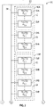
- Figure 1 is a schematic diagram illustrating portions of an example fluidic die 20.
- Fluidic die 20 comprises substrate 22, fluid actuator address line 24 and fluid actuators 32A, 32B (collectively referred to as fluid actuators 32) and fluid actuators 34A, 34B (collectively referred to as fluid actuators 34.
- Fluid actuator address line 24 comprises at least one electrically conductive wire or trace by which electrical signals are transmitted to logic associated with each of the fluid actuators 32, 34 to enable actuators 32, 34 for possible subsequent actuation during an actuation event.
- fluid actuator address line 24 comprises multiple electrically conductive wires or traces.
- fluid actuator address line 24 may comprise at least three bits or three individual bit lines.
- Fluid actuators 32 and 34 comprise devices or elements that cause displacement of a fluid in response to electrical actuation.
- the fluid actuators 32, 34 may include a piezoelectric membrane based actuator, a thermal resistor based actuator, an electrostatic membrane actuator, a mechanical/impact driven membrane actuator, a magneto-strictive drive actuator, or other such elements.
- Fluid actuators 32 have different operating characteristics as compared to fluid actuators 34.
- fluid actuators 32 have different energy demands or utilize different voltage levels, current or energy during actuation than that of fluid actuators 34.
- fluid actuators 32 are in the form of fluid ejectors whereas fluid actuators 34 are in the form of fluid pumps.
- a fluid ejector may comprise an actuator that displaces fluid in an ejection chamber through an orifice.
- a fluid pump may comprise an actuator that displaces fluid in a microfluidic channel.
- fluid actuators 32 and 34 may both comprise fluid ejectors, but where fluid actuators 32 and 34 have different drop weights or other different operational characteristics.
- fluid actuator 32 and 34 may both comprise fluid pumps, but where fluid actuators 32 and 34 have different energy voltage demands.
- fluid actuators 32A and 34A collectively, form a first set 40A of fluid actuators while fluid actuators 32B and 34B, collectively, form a second set 40B of fluid actuators.
- Sets 40A and 40B (collectively referred to as sets 40) extend adjacent to one another or are consecutive on substrate 22.
- Each of sets 40 comprises a subset 42 of fluid actuators 32 and a subset 44 of fluid actuators 34.
- Figure 1 illustrates such actuators 32, 34 physically arranged in columns, in other implementations, actuators 32, 34 may be in rows, arrays or other physical arrangements.
- Sets 40 form what may be referred to as primitives of fluidic die 20, each set having a same set of addresses.
- each fluid actuator in set 40A has an address that is the same as the address of a fluid actuator in set 40B.
- the addresses of the sets 40A and 40B are oppositely apportioned between the different types fluid actuators.
- the fluid actuators of each of sets 40 have a set of addresses comprising addresses A 1,1 to A 1,n and addresses A 2,1 to A 2,n .
- fluid actuators 32A have addresses A 1,1 to A 1,n
- in set 40B fluid actuators 32B have addressesA 2,1 to A2n.
- fluid actuators 34A have addresses A 2,1 to A 2,n
- fluid actuators 34B have addresses A 1,1 to A 1,n .
- a single address enabling event on address line 24 concurrently enables different types of fluid actuators in the different sets 40.
- a single address enabling event resulting in the transmission of address enabling signals across address line 24 to enable address A 1,1 may result in fluid actuator 32A (of a first type T1) of set 40A being enabled for a subsequent actuation event while also resulting in fluid actuator 34B (of a second type T2) being enabled for the same subsequent actuation event.
- a single address enabling event resulting in the transmission of address enabling signals across address line 24 to enable address A 2,1 may result in fluid actuator 34A (of the second type T2) of set 40A being enabled for a subsequent actuation event while also resulting in fluid actuator 32B (of the first type T1) being enabled for the same subsequent actuation event.
- the example addressing scheme of fluidic die 20 may facilitate more flexibility in the actuation order of fluid actuators 32, 34.
- the example addressing scheme of fluid die 20 may facilitate reduced peak currents.
- the number of fluid ejectors is spread out over the total number of addresses in each set 40, resulting in half, rather than all, of the total number of fluid ejectors being enabled for possible actuation during a subsequent actuation event.
- the first half of the fluid ejectors may be enabled for possible actuation during a first actuation event while a second half of the fluid actuators may be enabled for possible actuation during a second actuation event.
- fluid actuators 32 and 34 are each schematically illustrated as comprising fluid actuators that are clustered or grouped in each of sets 40, it should be appreciated that the different fluid actuators 32, 34 may be interspersed amongst one another in each set 40. For example, in one implementation, fluid actuators 32 and 34 may alternate with one another in each set 40. Fluid actuators 32 may have even addresses while fluid actuators 34 have odd addresses, or vice versa. Regardless of location or relative positioning on die 20, each fluid actuator of a first type in set 40A with a given address has a corresponding fluid actuator of a second type in 40B with the same given address.
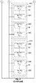
- Figure 2 is a schematic diagram of portions of fluidic die 120.
- Fluidic die 120 is similar to fluidic die 20 except that fluidic die 120 is illustrated as comprising at least four consecutive primitives or sets 40 of fluid actuators 32, 34. Those components of fluidic die 120 which correspond to components of fluidic die 20 are numbered similarly. Although Figure 2 illustrates such actuators 32, 34 physically arranged in columns, in other implementations, actuators 32, 34 may be in rows, arrays or other physical arrangements.
- fluidic die 120 additionally comprises sets 40C and 40D of fluid actuators 32C, 34C, 32D, 34D, respectively.
- Fluid actuators 32C, 32D may be similar to fluid actuators 32A and 32B, respectively.
- fluid actuators 34C, 34D may be similar to fluid actuators 34A and 34B, respectively.
- fluid actuators 32A-32C and fluid actuators 34A-34D are collectively referred to as fluid actuators 32 and fluid actuators 34, respectively.
- Fluid actuators 32 and 34 are all connected to fluid actuator address line 24 which transmits address enabling signals as part of an address enabling event to enable a selected address long address line 24 for possible subsequent actuation during a subsequent actuation event.
- a single address enabling event resulting in the transmission of address enabling signals across address line 24 to enable address A1,1 may result in fluid actuator 32A (of a first type T1) of set 40A being enabled for a subsequent actuation event, fluid actuator 34B (of a second type T2) being enabled for the subsequent actuation event, fluid actuator 32C (of the first type T1) of set 40C being enabled for the subsequent actuation event and fluid actuator 34D (of the second type T2) being enabled for the same subsequent actuation event.
- a single address enabling event resulting in the transmission of address enabling signals across address line 24 to enable address A2,1 may result in fluid actuator 34A (of the second type T2) of set 40A being enabled for a subsequent actuation event, fluid actuator 32B (of the first type T1) being enabled for the subsequent actuation event, fluid actuator 34C (of the second type T2) of set 40C being enabled for the subsequent actuation event and fluid actuator 32D (of the first type T1) being enabled for the same subsequent actuation event.
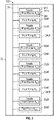
- Figure 3 is a schematic diagram illustrating a portion of an example fluidic die 220.
- Fluidic die 220 is similar to fluidic dies 20 and 120 except that fluidic die 220 is specifically illustrated as having different types of fluid actuators in the form of fluid ejectors and fluid pumps that alternate with one another along address line 24.
- the fluid ejectors have different energy voltage demands as compared to the fluid pumps.
- Those components of fluidic die 220 which correspond to components of fluidic dies 20 and 120 are numbered similarly.
- fluidic die 220 comprises fluid actuators in the form of fluid ejectors 232A, 232B (collectively referred to as fluid ejectors 232) and fluid actuators in the form of fluid pumps 234A, 234B (collectively referred to as fluid pumps 234).
- Each fluid ejector 232 is part of a larger nozzle 250, wherein each nozzle 250 has an orifice through which fluid is ejected through the displacement caused by the associated fluid ejector 232.
- fluid ejectors 232/nozzles 250 and fluid pumps 234 alternate along address line 24, wherein fluid ejector 232 and fluid pumps 234 are paired, wherein a fluid pump 234 circulates fluid to and/or from a paired or associated fluid ejector 232/nozzle 250.
- the interspersed nozzles 250 and fluid pumps 234 may have other arrangements or patterns.
- fluid ejectors 232 and fluid pumps 234 form two sets 240A and 240B (collectively referred to as sets 240) of fluid actuators.
- Each of sets 240 comprises a subset 242 of fluid ejectors 232 and a subset 244 of fluid pumps 234.
- Sets 240 form what may be referred to as primitives of fluidic die 220, each set having a same set of addresses.
- each fluid actuator in set 240A has an address that is the same as the address of a fluid actuator in set 240B.
- the addresses of the sets 240A and 240B are oppositely apportioned between the different types fluid actuators.
- the fluid actuators of each of sets 40 have a set of addresses comprising addresses A1 to An.
- the fluid ejectors 232A of set 240A have even addresses (for example, 0, 2, 4 ...n-1) while the fluid pumps 234 of set 240A have the odd addresses (for example, 1,3,5 ...n).
- the fluid ejectors 232B of set 240B have odd addresses (for example, 1, 3,5 ...n) while the fluid pumps 234B have even addresses (for example, 0, 2, 4 ...n-1).
- a single address enabling event on address line 24 concurrently enables different types of fluid actuators in the different sets 240.
- a single address enabling event resulting in the transmission of address enabling signals across address line 24 to enable address A3 may result in fluid ejector 232A at address A3 of set 240A being enabled for a subsequent actuation event while also resulting in fluid pump 234B at address A3 of set 240B being enabled for the same subsequent actuation event.
- a single address enabling event resulting in the transmission of address enabling signals across address line 24 to enable address A4 may result in fluid pump 234A at address A4 of set 40A being enabled for a subsequent actuation event while also resulting in ejector 232B at address A4 of set 240B being enabled for the same subsequent actuation event.
- the example addressing scheme of fluidic die 220 may facilitate more flexibility in the actuation order of fluid ejectors 232 and fluid pumps 234. In examples where fluid ejectors 232 and fluid pumps 234 have different energy demands, the example addressing scheme of fluid die 220 may facilitate reduced peak currents.
- the number of fluid ejectors is spread out over the total number of addresses in each of sets 240, resulting in half, rather than all, of the total number of fluid ejectors being enabled for possible actuation during a subsequent actuation event
- the first half of the fluid ejectors may be enabled for possible actuation during a first actuation event while a second half of the fluid actuators may be enabled for possible actuation during a second actuation event.
- Figures 4 and 5 schematically illustrate portions of an example fluid ejection system 300 having a fluid ejection controller 310 and a fluidic die 320 with the same address scheme as described above with respect to fluidic die 220.
- fluidic die 320 comprises an array of fluid actuators in the form of fluid ejectors 332 and fluid pumps 334 connected to a fluid actuator address line 24.
- Fluid ejectors 332 and fluid pumps 334 are paired along address line 24, wherein each of the fluid pumps 334 circulates fluid to and/or from an associated fluid ejector 332.
- Fluid ejectors 332 and fluid pumps 334 are arranged in primitives or sets 340A, 340B of fluid ejectors/fluid pumps.
- FIG. 4 depicts a single pair of a fluid ejector 332 and an associated pump 334 for each of sets 340A, 340B, it should be appreciated that sets 340A, 340B may each include an array of fluid ejector 332/fluid pump 334 pairs along address line 24.
- each fluid ejector 332 is part of a nozzle 350 having an ejection chamber 352 having an orifice 354 and in which the fluid ejector 332 is located.
- Each ejection chamber 352 is fluidly connected to a fluid supply 356 by a fluid input 358 and a microfluidic channel 360.
- each fluid input 358 and microfluidic channel 360 facilitate circulation of fluid into ejection chamber 350, through and across ejection chamber 352 and out of ejection chamber 352 back to fluid supply 356. In the example illustrated, such circulation is facilitated by fluid pump 334 within microfluidic channel 360.
- fluid supply 356 comprises an elongate slot supplying fluid to each of the fluid ejectors 332 in each of the sets 340 of die 320.
- fluid supply 356 may comprise an array of ink feed holes.
- fluid supply 356 further supplies fluid to primitives or sets 340 of fluid ejector 332 and fluid pumps 334 located on an opposite side of fluid supply 356.
- fluidic die 320 may comprise multiple primitives are sets similar to the arrangement shown on fluidic die 120.
- each fluid ejector 332 and each fluid pump 334 comprises triggering logic (L) 370 which controls the firing or actuation of the fluid actuator, either in the form of fluid ejector 332 or in the form of fluid pump 334.
- Figure 5 schematically illustrates one example of triggering logic 370 on fluidic die 320 and associated with a fluid actuator in the form of a fluid ejector 332 or a fluid pump 334.
- triggering logic 370 comprises a transistor 372 and logic element (LE) 374.
- Transistor 372 is a switch selectively transmitting a voltage Vpp to fluid ejector 332 or fluid pump 334 in response to a signal received from logic element 374.
- the logic element 374 comprises electronic circuitry and components that pass and actuation or fire signal to transistor 372 in response to the primitive enabling line or address line 378 and the address line 24 both being active.
- logic element 374 comprises a gate or other AND logic circuitry (schematically illustrated) that transmits the control signals or fire pulse signal received from a fire pulse line 376 to the gate of transistor 372 in response to receiving an address signal from address line 24 and also receiving a primitive enabling data signal from a data, primitive select or primitive enabling line 378.
- fire pulse line 376 and primitive enabling line 378 also reside on substrate 22 of fluidic die 320.
- logic element 374 may comprise other forms of electrical circuitry.
- primitive enabling data signals and fire pulse signals may be combined upstream (such as at the primitive level) or may be inverted.
- the different types of fluid actuators such as the fluid ejectors 332 and the fluid pumps 334 may have separate or dedicated fire pulse lines 376 that transmit fire pulse with different characteristics, such as fire pulses with different frequencies, amplitude and/or durations.
- each of the fluid ejectors 332 may be connected to a first fire pulse line 376 while each of the fluid pumps 334 are connected to a separate and different fire pulse line 376.
- Primitive enabling line 378 receives a data signal when the particular primitive or set 340 to which the fluid ejector 332, fluid pump 334 belongs, is to be enabled for firing.
- the fluid ejector 332, fluid actuator 334 is actuated in accordance with the fire pulse received on line 376.
- Fluid ejection controller 310 transmits packets of information to fluidic die 320, wherein logic on die 320 parses out instructions pertaining to which address is to be enabled for a particular actuation event and which printers or sets 340 are to also be enabled such that those fluid ejector 332 and fluid pumps 334 of the different sets 340 that receive both address enabling signals and primitive enabling signals are actuated pursuant to the fire pulse signal received on line 376.
- Figure 6 is a flow diagram of an example method 400 for actuating fluid actuators having different operating characteristics and arranged in different primitives are sets on a fluidic die.
- method 400 may also be carried out with any sets of different fluid actuators having different operating characteristics.
- method 400 may likewise be carried out with sets of different fluid ejectors, each set having at least two types of fluid ejectors, such as different types of fluid ejectors having different drop weights or other different operational characteristics.
- Method 400 may likewise be carried out with sets of different fluid pumps, each set having at least two types of fluid pumps having different energy demands
- address line 24 transmits address enabling signals to each of a first set 340A and a second set 340B of fluid actuators 332, 334.
- the address enabling signals enable a single address on the fluid actuators line 24 of die 20.
- a first actuator of a first type of fluid actuators in a first set of fluid actuators 340A and having the address enabled by the address enabling signals is enabled for actuation during a subsequent actuation event.
- the address enabling signals are received by the logic element 374 of the first fluid actuator.
- a second actuator of a second type of fluid actuators in a second set 340B of fluid actuators and having the address enabled by the address enabling signals is enabled for actuation during a subsequent actuation event.
- the address enabling signals are received by the logic element 374 of the second fluid actuator.
- the first fluid actuator and the second fluid actuator are different types of fluid actuators. With respect to the example fluidic die 320, the first actuator may be in the form of fluid ejector 332 while the second actuator may be in the form of fluid pump 334, or vice versa.
- primitive enabling signals (also sometimes referred to as data signals) are transmitted to each fluid actuator, each fluid ejector 332 and each fluid pump 334, of the first set 340A of fluid actuators and of the second set 340B of fluid actuators.
- the primitive enabling signals are received by the logic element 374 across lines 378 of each fluid ejector 332 and each fluid pump 334, of the first set 340A of fluid actuators and of the second set 340B of fluid actuators.
- fire pulse signals are transmitted to the first set of fluid actuators and the second set of fluid actuators.
- the fire pulse signals control the timing, frequency and duration of each logical pulse transmitted to a fluid actuator during actuation.
- the fire pulse signals may be transmitted independent of the primitive enabling and address signals. In other implementations, the fire pulse signals may be combined upstream with the primitive enabling/data signals.
- the first actuator of the first type in the first set 340A of fluid actuators is actuated pursuant to the fire pulse received associated fire pulse line 376.
- the second actuator of the second type in the second set 340B of fluid actuators is actuated pursuant to the fire pulse received on the associated fire pulse line 376.
- the first actuator may receive an address enabling signal on address line 24 while not receiving primitive enabling signals on primitive enabling line 378, result in the first actuator not being actuated or fired.
- the first actuator may receive a primitive enabling signal on primitive enabling line 378 while not receiving an address enabling signal on address line 24, resulting in the first actuator not being fired. The same logic applies with respect to the second actuator.
- FIG. 7 is a schematic diagram of another example fluidic die 520.
- Microfluidic die 520 is similar to microfluidic die 320 except that microfluidic die 520 is illustrated as comprising a fluid supply in the form of a fluid slot 556 that supplies fluid to 3136 fluid actuators, alternating between fluid pumps and fluid ejectors, on either side of slot 556 and arranged in primitives or sets 540 (1-391), each set including eight fluid actuators, four fluid ejectors and four fluid pumps.
- the ejectors are associated with a nozzle orifice 354 while the pumps are contained within are associated with a microfluidic channel 360.
- Figure 7 illustrates the use of the addressing scheme described above with respect to fluidic dies 20, 120 and 320 on a larger scale.
- the set of addresses in the sets are primitives 540 oppositely assigned to the ejectors 332 and pumps 334.
- the ejectors have even addresses (0,2,4,6) while the pumps have odd addresses (1,3,5,7).
- the ejectors have odd addresses (1,3,5,7) while the pumps have even addresses (0,2,4,61,3,5,7)
- the same schemas apply with respect to primitives 1, 3, primitives 390, 392, primitive 389, 391 and so on.
- the example addressing scheme of fluidic die 520 may facilitate more flexibility in the actuation order of fluid ejectors 332 and fluid pumps 334.
- the example addressing scheme of fluid die 520 may facilitate reduced peak currents.
- the number of fluid ejectors is spread out over the total number of addresses in each of sets 540, resulting in half, rather than all, of the total number of fluid ejectors being enabled for possible actuation during a subsequent actuation event.
- the first half of the fluid ejectors may be enabled for possible actuation during a first actuation event while a second half of the fluid actuators may be enabled for possible actuation during a second actuation event.
- FIG 8 is a schematic diagram of a portion of another example fluidic die 620 having data pad 621, data parser 622 and address line 624.
- Fluidic die 620 additionally comprises each of those components illustrated and described above respect to Figures 4 and 5 such as primitives or sets 340 of different fluid ejectors in the form of fluid ejectors 332 and fluid pumps 334 as well as fluid input 358, microfluidic channel 360 and the components of nozzle 350 such as ejection chamber 352 and orifice 354.
- each set 340 comprises eight fluid actuators, four fluid ejectors 332 and four fluid pump 334.
- such as primitives or sets may comprise a greater or smaller number of such fluid actuators.
- Each fluid ejector 332, fluid pump 334 may comprise the triggering logic 370 as illustrated and described above, but where fluid actuator address line 24 is replaced with fluid actuator address line 624 as illustrated in Figure 8 .
- Data pad 621 comprise electric connections by which data packets are received from fluid ejection controller 310 (shown in Figure 5 )
- data parser 622 comprises electronics or logic that parses the data packet to identify a designated fluid actuator address to be enabled for a particular actuation event.
- Data parser 622 may transmit signals along address line 624 based upon the designated fluid actuator address.
- Fluid actuator address line 624 comprises address bit lines 680, complementary address bit lines 682 and address decoding logic elements 682, Address bit lines 680 comprise electrically conductive wires or traces on substrate 22 that represent three bits, Addr(0), Addr (1) and Addr(2) and which are connected to or not connected to respective address decoding logic elements 682 based upon the binary address of the fluid actuator 332, 334 connected to the respective address decoding logic elements 682.
- the topmost fluid ejector 332 of set 340A with an address of "0" has an associated logic element 682 that is not connected to Addr(2) (a bit value of 0), that is not connected to Addr(1) (a bit value of 0) and that is not connected to Addr(0) (a bit value of 0), forming a binary value of 000 or zero.
- the topmost fluid pump 334 of set 340A with an address of "1” has an associated logic element 682 that is not connected to Addr(2) (a bit value of0), that is not connected to Addr(1) (a bit value of 0) and that is connected to Addr(0) (a bit value of 1), forming a binary value of 001 or one.
- the next actuator in the form of a fluid ejector having address "2" has an associated logic element 682 that is not connected to Addr(2) (a bit value of 0), that is connected to Addr(1) (a bit value of 1) and that is not connected to Addr(0) (a bit value of 0), forming a binary address value of 010 or two.
- Addr(2) a bit value of 0
- Addr(1) a bit value of 1
- Addr(0) a bit value of 0
- set 340B (and any other primitives or sets of fluidic die 620).
- the set of addresses 0-7 in set 340B are oppositely assigned to the fluid ejectors 332 and fluid pump 334. Instead of fluid ejectors 332 being assigned even addresses and the fluid pumps 334 being assigned odd addresses, the fluid pumps are assigned even addresses while the fluid ejectors are assigned odd addresses.
- the address bit line 680 of fluid actuator address line 624 are connected to the logic element 682 of each fluid ejector 332 or fluid pump 334 based upon the address of the fluid ejector 332 or fluid pump 334.
- the fluid ejector 332 having an address of "7" has an address decoding logic element 682 that is connected to Addr(2) (a bit value of 1), that is connected to Addr(1) (a bit value of 1), and that is connected to Addr(0) (a bit value of one), forming a binary address value of 111 or seven.
- the complementary address bit lines 682 cooperate with address bit lines 680 to transmit signals such that an individual address decoding logic element 682 transmits an address enabling signal to its respective fluid ejector 332 or fluid pump 334 in response to an individual fluid ejector 332 or fluid pump 334 being addressed by line 624.
- the complementary address bit lines 682 comprise electrically conductive wires or traces on substrate 22 that are connected to or not connected to the logic element 682 of the different fluid ejectors 332 and fluid pumps 334 based upon the address of the respective fluid ejector 332, fluid pumps 334.
- the complementary address bit lines 682 for a particular logic element 682 for a particular fluid ejector 332 or fluid pump 334 have connections that are the opposite of the connections of the respective address bit line 680 to the same particular fluid ejector 332 or fluid pump 334.
- the fluid ejector 332 with an address of "4" has a logic element 682 connected to address bit line Addr(2) but not connected to the remaining address bit lines Addr(1) and Addr(2) to form a binary address of 100 with a value of 4.
- the same address decoding logic element 682 for the fluid ejector 332 having an address of "4" is connected to address bit lines 682 in a complementary or opposite fashion, not being connected to Addr(2) while being connected to Addr(1) and Addr(0).
- the connections between each of the logic element 682 and the address bit line 680 and complementary address bit line 682 is made on substrate 22 with metal 2 layer jumpers.
- the address to be enabled in each of the sets 340 of fluid ejector 332 and fluid pumps 334 is carried out by selectively connecting the different address bit line 680 and complementary address bit line 682 to a high "1" or a low “0" voltage level Such selective connection may be made by actuation logic utilizing transistors or other switches.
- the address bit lines Addr(2) and Addr(0) of the address bit lines 680 and the complementary address bit line N Addr(1) are connected to a high "1" voltage level.
- the address bit line Addr(1) of the address bit line 680 and the address bit lines N Addr(2) and N Addr(0) of the complementary address bit lines 682 are connected to a low "0" voltage, either I a null or zero voltage or a negative voltage.
- the other fluid ejectors 332 and fluid pumps 334 may receive enabling signals via fluid actuator address line 624 in a similar fashion.
- address decoding logic elements 682 comprise AND logic such as a gate or other electronic circuitry that provide AND logic, wherein the output results in response to all of the input lines being active or the signals.
- address decoding logic elements 682 may comprise other electronic circuitry that decodes the address being transmitted along bit lines 680 and 682.
- addresses may be transmitted along address data line 624 using other numbers or combinations of bit lines as well as other address encoding circuitry or elements.
Landscapes
- Jet Pumps And Other Pumps (AREA)
- Micromachines (AREA)
- Ink Jet (AREA)
- Particle Formation And Scattering Control In Inkjet Printers (AREA)
- Control Of Positive-Displacement Pumps (AREA)
Claims (11)
- Fluidische Prägeplatte (20, 120, 220), die Folgendes umfasst:ein Substrat (22), das eine Fluidbedienungselementadressenleitung (24) trägt;eine erste Gruppe von Fluidbedienungselementen (32, 34), die mit der Fluidbedienungselementadressenleitung (24) verbunden sind, wobei die erste Gruppe von Fluidbedienungselementen (32, 34) Folgendes umfasst:eine erste Untergruppe von Fluidbedienungselementen (32, 34) einer ersten Art von Fluidbedienungselementen; undeine zweite Untergruppe von Fluidbedienungselementen (32, 34) einer zweiten Art von Fluidbedienungselementen, die andere Betriebsmerkmale als die erste Art von Fluidbedienungselementen aufweisen;eine zweite Gruppe von Fluidbedienungselementen (32, 34), die mit der Fluidbedienungselementadressenleitung (24) verbunden sind, wobei die zweite Gruppe von Fluidbedienungselementen (32, 34) Folgendes umfasst:eine dritte Untergruppe von Fluidbedienungselementen (32, 34) der ersten Art; undeine vierte Untergruppe von Fluidbedienungselementen (32, 34) der zweiten Art;dadurch gekennzeichnet, dass eines der ersten Untergruppe von Fluidbedienungselementen (32, 34) und eines der vierten Untergruppe von Fluidbedienungselementen (32, 34) Adressen aufweisen, um beide durch ein einzelnes Adressenaktivierungsereignis auf der Fluidbedienungselementadressenleitung (24) aktiviert zu werden.
- Fluidische Prägeplatte nach Anspruch 1, wobei die erste Untergruppe von Fluidbedienungselementen (32, 34) und die vierte Untergruppe von Fluidbedienungselementen (32, 34) jeweils eine erste Gruppe von Adressen aufweisen und wobei die zweite Untergruppe von Fluidbedienungselementen (32, 34) und die dritte Untergruppe von Fluidbedienungselementen (32, 34) jeweils eine zweite Gruppe von Adressen aufweisen.
- Fluidische Prägeplatte nach Anspruch 2, wobei die erste Gruppe von Adressen geradzahlige Adressen sind und wobei die zweite Gruppe von Adressen ungeradzahlige Adressen sind.
- Fluidische Prägeplatte nach Anspruch 1, wobei die erste Art von Fluidbedienungselementen (32, 34) einen ersten Bedienungsenergiebedarf aufweist und wobei die zweite Art von Fluidbedienungselementen (32, 34) einen zweiten Bedienungsenergiebedarf aufweist, der anders als der erste Bedienungsenergiebedarf ist.
- Fluidische Prägeplatte nach Anspruch 3, wobei die erste Art von Fluidbedienungselementen (32, 34) dazu dient, Fluid durch entsprechende Düsen auszustoßen, und wobei die zweite Art von Fluidbedienungselementen (32, 34) dazu dient, Fluid zu einer Brennkammer zu zirkulieren.
- Fluidische Prägeplatte nach Anspruch 1, wobei die erste Art von Fluidbedienungselementen (32, 34) dazu dient, Fluid durch entsprechende Düsen auszustoßen, und wobei die zweite Art von Fluidbedienungselementen (32, 34) dazu dient, Fluid zu einer Brennkammer zu zirkulieren.
- Fluidische Prägeplatte nach Anspruch 1, die ferner eine dritte Gruppe von Fluidbedienungselementen (32, 34), die mit der Fluidbedienungselementadressenleitung (24) verbunden ist, angrenzend an die zweite Gruppe von Fluidbedienungselementen (32, 34) umfasst, wobei die dritte Gruppe von Fluidbedienungselementen (32, 34) zwischen der ersten Gruppe von Fluidbedienungselementen (32, 34) und der zweiten Gruppe von Fluidbedienungselementen (32, 34) liegt, wobei die dritte Gruppe von Fluidbedienungselementen (32, 34) Folgendes umfasst:eine fünfte Untergruppe von Fluidbedienungselementen (32, 34) der ersten Art von Fluidbedienungselementen; undeine sechste Untergruppe von Fluidbedienungselementen (32, 34) der zweiten Art von Fluidbedienungselementen, wobei eines der fünften Untergruppe von Fluidbedienungselementen (32, 34) eine Adresse aufweist, um durch das einzelne Aktivierungsereignis auf der Fluidbedienungselementadressenleitung (24) aktiviert zu werden.
- Fluidische Prägeplatte nach Anspruch 1, wobei die
Fluidbedienungselementadressenleitung (24) eine erste Gruppe von Bitleitungen und eine zweite Gruppe von komplementären Bitleitungen umfasst, wobei das eine aus der ersten Untergruppe von Fluidbedienungselementen (32, 34) und das eine der vierten Untergruppe von Fluidbedienungselementen (32, 34) jeweils eine Logik aufweisen, die mit einer gleichen Kombination der ersten Gruppe von Bitleitungen und einer gleichen Kombination der zweiten Gruppe von komplementären Bitleitungen gekoppelt ist. - Fluidische Prägeplatte nach Anspruch 1, wobei sich Fluidbedienungselemente der ersten Untergruppe von Fluidbedienungselementen (32, 34) mit Fluidbedienungselementen der zweiten Untergruppe von Fluidbedienungselementen (32, 34) in der ersten Gruppe von Fluidbedienungselementen (32, 34) abwechseln und wobei Fluidbedienungselemente der dritten Untergruppe von Fluidbedienungselementen (32, 34) mit Fluidbedienungselementen der vierten Untergruppe von Fluidbedienungselementen (32, 34) in der zweiten Gruppe von Fluidbedienungselementen (32, 34) abwechseln.
- Verfahren (400), das Folgendes umfasst:Übertragen (404) von Adressenaktivierungssignalen, die eine einzelne Adresse auf einer Fluidbedienungselementadressenleitung einer fluidischen Prägeplatte aktivieren, an jeweils eine erste Gruppe von Fluidbedienungselementen und eine zweite Gruppe von Fluidbedienungselementen;Aktivieren (406) eines ersten Fluidbedienungselements einer ersten Art von Fluidbedienungselementen, das eine Adresse aufweist, in der ersten Gruppe von Fluidbedienungselementen, als Reaktion auf die Adressenaktivierungssignale; undAktivieren (408) eines zweiten Fluidbedienungselements einer zweiten Art von Fluidbedienungselementen, das die Adresse aufweist, in der zweiten Gruppe von Fluidbedienungselementen, als Reaktion auf die Adressenaktivierungssignale, wobei die zweite Art von Fluidbedienungselementen jeweils ein Betriebsmerkmal aufweist, das anders als das der ersten Art von Fluidbedienungselementen ist;Übertragen (410) von Primitivaktivierungssignalen an die erste Gruppe von Fluidbedienungselementen und die zweite Gruppe von Fluidbedienungselementen;Bedienen (414) des ersten Fluidbedienungselements als Reaktion darauf, dass das erste Fluidbedienungselement eine Kombination aus den Adressenaktivierungssignalen und den Primitivaktivierungssignalen empfängt; undBedienen (416) des zweiten Fluidbedienungselements als Reaktion darauf, dass das zweite Fluidbedienungselements eine Kombination aus den Adressenaktivierungssignalen und den Primitivaktivierungssignalen empfängt.
- Verfahren nach Anspruch 10, wobei das erste Fluidbedienungselement einen Fluidausstoßer umfasst und wobei das zweite Fluidbedienungselement eine Fluidpumpe umfasst.
Applications Claiming Priority (1)
| Application Number | Priority Date | Filing Date | Title |
|---|---|---|---|
| PCT/US2017/027709 WO2018190872A1 (en) | 2017-04-14 | 2017-04-14 | Fluidic die |
Publications (3)
| Publication Number | Publication Date |
|---|---|
| EP3548288A1 EP3548288A1 (de) | 2019-10-09 |
| EP3548288A4 EP3548288A4 (de) | 2020-09-16 |
| EP3548288B1 true EP3548288B1 (de) | 2022-08-17 |
Family
ID=63792670
Family Applications (1)
| Application Number | Title | Priority Date | Filing Date |
|---|---|---|---|
| EP17905302.0A Active EP3548288B1 (de) | 2017-04-14 | 2017-04-14 | Fluidische matrize |
Country Status (6)
| Country | Link |
|---|---|
| US (4) | US11034147B2 (de) |
| EP (1) | EP3548288B1 (de) |
| JP (1) | JP6887511B2 (de) |
| KR (1) | KR102261254B1 (de) |
| CN (1) | CN110267816B (de) |
| WO (1) | WO2018190872A1 (de) |
Families Citing this family (13)
| Publication number | Priority date | Publication date | Assignee | Title |
|---|---|---|---|---|
| WO2018190872A1 (en) * | 2017-04-14 | 2018-10-18 | Hewlett-Packard Development Company, L.P. | Fluidic die |
| JP7069714B2 (ja) * | 2017-12-28 | 2022-05-18 | セイコーエプソン株式会社 | 圧電方式プリントヘッドおよび圧電方式インクジェットプリンター |
| CN112714694B (zh) * | 2018-09-24 | 2022-12-20 | 惠普发展公司,有限责任合伙企业 | 连接到场效应晶体管的流体致动器 |
| WO2020106288A1 (en) * | 2018-11-21 | 2020-05-28 | Hewlett-Packard Development Company, L.P. | Fluidic dies with transmission paths having corresponding parasitic capacitances |
| US11413864B2 (en) | 2019-02-06 | 2022-08-16 | Hewlett-Packard Development Company, L.P. | Die for a printhead |
| PL3717257T3 (pl) * | 2019-02-06 | 2021-12-06 | Hewlett-Packard Development Company, L.P. | Komunikujący się komponent drukujący |
| CN113365841B (zh) | 2019-02-06 | 2022-10-04 | 惠普发展公司,有限责任合伙企业 | 用于打印头的管芯 |
| PT3710269T (pt) | 2019-02-06 | 2023-02-02 | Hewlett Packard Development Co | Componente de impressão de comunicação |
| ES2904246T3 (es) | 2019-02-06 | 2022-04-04 | Hewlett Packard Development Co | Troquel de un cabezal de impresión |
| CA3126053C (en) | 2019-02-06 | 2023-11-07 | Hewlett-Packard Development Company, L.P. | Die for a printhead |
| WO2021183104A1 (en) * | 2020-03-09 | 2021-09-16 | Hewlett-Packard Development Company, L.P. | Fluidic die with adjacent and orthogonal bond pad regions |
| JP2026054068A (ja) | 2024-09-13 | 2026-03-26 | キヤノン株式会社 | 液体吐出ヘッド及び液体吐出装置 |
| JP2026054102A (ja) | 2024-09-13 | 2026-03-26 | キヤノン株式会社 | 液体吐出ヘッド及び液体吐出装置 |
Family Cites Families (22)
| Publication number | Priority date | Publication date | Assignee | Title |
|---|---|---|---|---|
| US5648806A (en) | 1992-04-02 | 1997-07-15 | Hewlett-Packard Company | Stable substrate structure for a wide swath nozzle array in a high resolution inkjet printer |
| JPH0991967A (ja) * | 1995-09-21 | 1997-04-04 | Toshiba Corp | 半導体集積回路及び半導体記憶装置 |
| US6803989B2 (en) * | 1997-07-15 | 2004-10-12 | Silverbrook Research Pty Ltd | Image printing apparatus including a microcontroller |
| US7527357B2 (en) * | 1997-07-15 | 2009-05-05 | Silverbrook Research Pty Ltd | Inkjet nozzle array with individual feed channel for each nozzle |
| US6217147B1 (en) * | 1999-01-07 | 2001-04-17 | Hewlett-Packard Company | Printer having media advance coordinated with primitive size |
| US6754551B1 (en) * | 2000-06-29 | 2004-06-22 | Printar Ltd. | Jet print apparatus and method for printed circuit board manufacturing |
| US6829132B2 (en) * | 2003-04-30 | 2004-12-07 | Hewlett-Packard Development Company, L.P. | Charge control of micro-electromechanical device |
| JP2005177998A (ja) * | 2003-12-15 | 2005-07-07 | Canon Inc | プリント装置、プリントシステムおよびプリント装置の制御方法 |
| EP1963104A1 (de) | 2005-12-23 | 2008-09-03 | Telecom Italia S.p.A. | Tintenstrahldruckkopf und tintenstrahldruckverfahren |
| US8651604B2 (en) | 2007-07-31 | 2014-02-18 | Hewlett-Packard Development Company, L.P. | Printheads |
| US20090160898A1 (en) | 2007-12-20 | 2009-06-25 | Steven Wayne Bergstedt | Method and apparatus for controlling non-nucleating heating in a fluid ejection device |
| US7815273B2 (en) | 2008-04-01 | 2010-10-19 | Hewlett-Packard Development Company, L.P. | Fluid ejection device |
| JP5734414B2 (ja) * | 2010-05-11 | 2015-06-17 | ヒューレット−パッカード デベロップメント カンパニー エル.ピー.Hewlett‐Packard Development Company, L.P. | マルチモード印刷 |
| KR101686286B1 (ko) * | 2010-10-28 | 2016-12-28 | 휴렛-팩커드 디벨롭먼트 컴퍼니, 엘.피. | 순환 펌프를 구비한 유체 분사 어셈블리 |
| US8814293B2 (en) | 2012-01-13 | 2014-08-26 | Lexmark International, Inc. | On-chip fluid recirculation pump for micro-fluid applications |
| US9381739B2 (en) | 2013-02-28 | 2016-07-05 | Hewlett-Packard Development Company, L.P. | Fluid ejection assembly with circulation pump |
| WO2015047293A1 (en) * | 2013-09-27 | 2015-04-02 | Hewlett-Packard Development Company, L.P. | Printhead with separate address generator for ink level sensors |
| CN105934344B (zh) * | 2014-01-31 | 2018-01-12 | 惠普发展公司,有限责任合伙企业 | 交错的基元 |
| US10160203B2 (en) * | 2014-10-29 | 2018-12-25 | Hewlett-Packard Development Company, L.P. | Printhead fire signal control |
| WO2016089371A1 (en) | 2014-12-02 | 2016-06-09 | Hewlett-Packard Development Company, L.P. | Printhead nozzle addressing |
| EP3281802B1 (de) | 2015-02-13 | 2019-11-13 | Hewlett-Packard Development Company, L.P. | Flüssigkeitsausstossanordnung, drucksystem und verfahren zum betrieb eines druckkopf |
| WO2018190872A1 (en) * | 2017-04-14 | 2018-10-18 | Hewlett-Packard Development Company, L.P. | Fluidic die |
-
2017
- 2017-04-14 WO PCT/US2017/027709 patent/WO2018190872A1/en not_active Ceased
- 2017-04-14 CN CN201780084909.1A patent/CN110267816B/zh active Active
- 2017-04-14 JP JP2019543075A patent/JP6887511B2/ja active Active
- 2017-04-14 KR KR1020197022457A patent/KR102261254B1/ko active Active
- 2017-04-14 EP EP17905302.0A patent/EP3548288B1/de active Active
- 2017-04-14 US US16/474,268 patent/US11034147B2/en active Active
-
2021
- 2021-05-14 US US17/302,887 patent/US11618253B2/en active Active
-
2023
- 2023-02-23 US US18/113,610 patent/US20230191779A1/en not_active Abandoned
- 2023-02-24 US US18/114,148 patent/US20230202167A1/en not_active Abandoned
Also Published As
| Publication number | Publication date |
|---|---|
| JP6887511B2 (ja) | 2021-06-16 |
| KR20190102245A (ko) | 2019-09-03 |
| CN110267816A (zh) | 2019-09-20 |
| US20230202167A1 (en) | 2023-06-29 |
| CN110267816B (zh) | 2020-11-17 |
| US20230191779A1 (en) | 2023-06-22 |
| US11618253B2 (en) | 2023-04-04 |
| JP2020507497A (ja) | 2020-03-12 |
| EP3548288A1 (de) | 2019-10-09 |
| KR102261254B1 (ko) | 2021-06-04 |
| US11034147B2 (en) | 2021-06-15 |
| US20210260870A1 (en) | 2021-08-26 |
| EP3548288A4 (de) | 2020-09-16 |
| US20200122458A1 (en) | 2020-04-23 |
| WO2018190872A1 (en) | 2018-10-18 |
Similar Documents
| Publication | Publication Date | Title |
|---|---|---|
| US11618253B2 (en) | Fluidic die | |
| EP3212405B1 (de) | Druckkopfausstosssignalsteuerung | |
| CN100473528C (zh) | 用于排放液体的液体排放装置和方法 | |
| US10960661B2 (en) | Fluid ejection device circuit | |
| US11932014B2 (en) | Print component having fluidic actuating structures with different fluidic architectures | |
| US11117368B2 (en) | Fluidic die | |
| US11090924B2 (en) | Fluidic die with nozzle displacement mask register | |
| JP5031455B2 (ja) | 記録ヘッド用素子基板、記録ヘッド及び該記録ヘッドを用いた記録装置 | |
| US10967634B2 (en) | Fluidic die with drop weight signals | |
| EP0341929A2 (de) | Multiplexstromkreis |
Legal Events
| Date | Code | Title | Description |
|---|---|---|---|
| STAA | Information on the status of an ep patent application or granted ep patent |
Free format text: STATUS: THE INTERNATIONAL PUBLICATION HAS BEEN MADE |
|
| PUAI | Public reference made under article 153(3) epc to a published international application that has entered the european phase |
Free format text: ORIGINAL CODE: 0009012 |
|
| STAA | Information on the status of an ep patent application or granted ep patent |
Free format text: STATUS: REQUEST FOR EXAMINATION WAS MADE |
|
| 17P | Request for examination filed |
Effective date: 20190705 |
|
| AK | Designated contracting states |
Kind code of ref document: A1 Designated state(s): AL AT BE BG CH CY CZ DE DK EE ES FI FR GB GR HR HU IE IS IT LI LT LU LV MC MK MT NL NO PL PT RO RS SE SI SK SM TR |
|
| AX | Request for extension of the european patent |
Extension state: BA ME |
|
| DAV | Request for validation of the european patent (deleted) | ||
| DAX | Request for extension of the european patent (deleted) | ||
| A4 | Supplementary search report drawn up and despatched |
Effective date: 20200813 |
|
| RIC1 | Information provided on ipc code assigned before grant |
Ipc: B41J 2/135 20060101AFI20200807BHEP Ipc: B41J 2/07 20060101ALI20200807BHEP Ipc: B41J 2/045 20060101ALI20200807BHEP |
|
| GRAP | Despatch of communication of intention to grant a patent |
Free format text: ORIGINAL CODE: EPIDOSNIGR1 |
|
| STAA | Information on the status of an ep patent application or granted ep patent |
Free format text: STATUS: GRANT OF PATENT IS INTENDED |
|
| INTG | Intention to grant announced |
Effective date: 20220419 |
|
| GRAS | Grant fee paid |
Free format text: ORIGINAL CODE: EPIDOSNIGR3 |
|
| GRAA | (expected) grant |
Free format text: ORIGINAL CODE: 0009210 |
|
| STAA | Information on the status of an ep patent application or granted ep patent |
Free format text: STATUS: THE PATENT HAS BEEN GRANTED |
|
| AK | Designated contracting states |
Kind code of ref document: B1 Designated state(s): AL AT BE BG CH CY CZ DE DK EE ES FI FR GB GR HR HU IE IS IT LI LT LU LV MC MK MT NL NO PL PT RO RS SE SI SK SM TR |
|
| REG | Reference to a national code |
Ref country code: CH Ref legal event code: EP |
|
| REG | Reference to a national code |
Ref country code: DE Ref legal event code: R096 Ref document number: 602017060878 Country of ref document: DE |
|
| REG | Reference to a national code |
Ref country code: IE Ref legal event code: FG4D |
|
| REG | Reference to a national code |
Ref country code: AT Ref legal event code: REF Ref document number: 1511933 Country of ref document: AT Kind code of ref document: T Effective date: 20220915 |
|
| REG | Reference to a national code |
Ref country code: NL Ref legal event code: MP Effective date: 20220817 |
|
| REG | Reference to a national code |
Ref country code: LT Ref legal event code: MG9D |
|
| PG25 | Lapsed in a contracting state [announced via postgrant information from national office to epo] |
Ref country code: SE Free format text: LAPSE BECAUSE OF FAILURE TO SUBMIT A TRANSLATION OF THE DESCRIPTION OR TO PAY THE FEE WITHIN THE PRESCRIBED TIME-LIMIT Effective date: 20220817 Ref country code: RS Free format text: LAPSE BECAUSE OF FAILURE TO SUBMIT A TRANSLATION OF THE DESCRIPTION OR TO PAY THE FEE WITHIN THE PRESCRIBED TIME-LIMIT Effective date: 20220817 Ref country code: PT Free format text: LAPSE BECAUSE OF FAILURE TO SUBMIT A TRANSLATION OF THE DESCRIPTION OR TO PAY THE FEE WITHIN THE PRESCRIBED TIME-LIMIT Effective date: 20221219 Ref country code: NO Free format text: LAPSE BECAUSE OF FAILURE TO SUBMIT A TRANSLATION OF THE DESCRIPTION OR TO PAY THE FEE WITHIN THE PRESCRIBED TIME-LIMIT Effective date: 20221117 Ref country code: NL Free format text: LAPSE BECAUSE OF FAILURE TO SUBMIT A TRANSLATION OF THE DESCRIPTION OR TO PAY THE FEE WITHIN THE PRESCRIBED TIME-LIMIT Effective date: 20220817 Ref country code: LV Free format text: LAPSE BECAUSE OF FAILURE TO SUBMIT A TRANSLATION OF THE DESCRIPTION OR TO PAY THE FEE WITHIN THE PRESCRIBED TIME-LIMIT Effective date: 20220817 Ref country code: LT Free format text: LAPSE BECAUSE OF FAILURE TO SUBMIT A TRANSLATION OF THE DESCRIPTION OR TO PAY THE FEE WITHIN THE PRESCRIBED TIME-LIMIT Effective date: 20220817 Ref country code: FI Free format text: LAPSE BECAUSE OF FAILURE TO SUBMIT A TRANSLATION OF THE DESCRIPTION OR TO PAY THE FEE WITHIN THE PRESCRIBED TIME-LIMIT Effective date: 20220817 |
|
| REG | Reference to a national code |
Ref country code: AT Ref legal event code: MK05 Ref document number: 1511933 Country of ref document: AT Kind code of ref document: T Effective date: 20220817 |
|
| PG25 | Lapsed in a contracting state [announced via postgrant information from national office to epo] |
Ref country code: PL Free format text: LAPSE BECAUSE OF FAILURE TO SUBMIT A TRANSLATION OF THE DESCRIPTION OR TO PAY THE FEE WITHIN THE PRESCRIBED TIME-LIMIT Effective date: 20220817 Ref country code: IS Free format text: LAPSE BECAUSE OF FAILURE TO SUBMIT A TRANSLATION OF THE DESCRIPTION OR TO PAY THE FEE WITHIN THE PRESCRIBED TIME-LIMIT Effective date: 20221217 Ref country code: HR Free format text: LAPSE BECAUSE OF FAILURE TO SUBMIT A TRANSLATION OF THE DESCRIPTION OR TO PAY THE FEE WITHIN THE PRESCRIBED TIME-LIMIT Effective date: 20220817 Ref country code: GR Free format text: LAPSE BECAUSE OF FAILURE TO SUBMIT A TRANSLATION OF THE DESCRIPTION OR TO PAY THE FEE WITHIN THE PRESCRIBED TIME-LIMIT Effective date: 20221118 |
|
| PG25 | Lapsed in a contracting state [announced via postgrant information from national office to epo] |
Ref country code: SM Free format text: LAPSE BECAUSE OF FAILURE TO SUBMIT A TRANSLATION OF THE DESCRIPTION OR TO PAY THE FEE WITHIN THE PRESCRIBED TIME-LIMIT Effective date: 20220817 Ref country code: RO Free format text: LAPSE BECAUSE OF FAILURE TO SUBMIT A TRANSLATION OF THE DESCRIPTION OR TO PAY THE FEE WITHIN THE PRESCRIBED TIME-LIMIT Effective date: 20220817 Ref country code: ES Free format text: LAPSE BECAUSE OF FAILURE TO SUBMIT A TRANSLATION OF THE DESCRIPTION OR TO PAY THE FEE WITHIN THE PRESCRIBED TIME-LIMIT Effective date: 20220817 Ref country code: DK Free format text: LAPSE BECAUSE OF FAILURE TO SUBMIT A TRANSLATION OF THE DESCRIPTION OR TO PAY THE FEE WITHIN THE PRESCRIBED TIME-LIMIT Effective date: 20220817 Ref country code: CZ Free format text: LAPSE BECAUSE OF FAILURE TO SUBMIT A TRANSLATION OF THE DESCRIPTION OR TO PAY THE FEE WITHIN THE PRESCRIBED TIME-LIMIT Effective date: 20220817 Ref country code: AT Free format text: LAPSE BECAUSE OF FAILURE TO SUBMIT A TRANSLATION OF THE DESCRIPTION OR TO PAY THE FEE WITHIN THE PRESCRIBED TIME-LIMIT Effective date: 20220817 |
|
| REG | Reference to a national code |
Ref country code: DE Ref legal event code: R097 Ref document number: 602017060878 Country of ref document: DE |
|
| PG25 | Lapsed in a contracting state [announced via postgrant information from national office to epo] |
Ref country code: SK Free format text: LAPSE BECAUSE OF FAILURE TO SUBMIT A TRANSLATION OF THE DESCRIPTION OR TO PAY THE FEE WITHIN THE PRESCRIBED TIME-LIMIT Effective date: 20220817 Ref country code: EE Free format text: LAPSE BECAUSE OF FAILURE TO SUBMIT A TRANSLATION OF THE DESCRIPTION OR TO PAY THE FEE WITHIN THE PRESCRIBED TIME-LIMIT Effective date: 20220817 |
|
| PLBE | No opposition filed within time limit |
Free format text: ORIGINAL CODE: 0009261 |
|
| STAA | Information on the status of an ep patent application or granted ep patent |
Free format text: STATUS: NO OPPOSITION FILED WITHIN TIME LIMIT |
|
| PG25 | Lapsed in a contracting state [announced via postgrant information from national office to epo] |
Ref country code: AL Free format text: LAPSE BECAUSE OF FAILURE TO SUBMIT A TRANSLATION OF THE DESCRIPTION OR TO PAY THE FEE WITHIN THE PRESCRIBED TIME-LIMIT Effective date: 20220817 |
|
| 26N | No opposition filed |
Effective date: 20230519 |
|
| PG25 | Lapsed in a contracting state [announced via postgrant information from national office to epo] |
Ref country code: SI Free format text: LAPSE BECAUSE OF FAILURE TO SUBMIT A TRANSLATION OF THE DESCRIPTION OR TO PAY THE FEE WITHIN THE PRESCRIBED TIME-LIMIT Effective date: 20220817 |
|
| REG | Reference to a national code |
Ref country code: CH Ref legal event code: PL |
|
| GBPC | Gb: european patent ceased through non-payment of renewal fee |
Effective date: 20230414 |
|
| PG25 | Lapsed in a contracting state [announced via postgrant information from national office to epo] |
Ref country code: LU Free format text: LAPSE BECAUSE OF NON-PAYMENT OF DUE FEES Effective date: 20230414 |
|
| REG | Reference to a national code |
Ref country code: BE Ref legal event code: MM Effective date: 20230430 |
|
| PG25 | Lapsed in a contracting state [announced via postgrant information from national office to epo] |
Ref country code: MC Free format text: LAPSE BECAUSE OF FAILURE TO SUBMIT A TRANSLATION OF THE DESCRIPTION OR TO PAY THE FEE WITHIN THE PRESCRIBED TIME-LIMIT Effective date: 20220817 |
|
| PG25 | Lapsed in a contracting state [announced via postgrant information from national office to epo] |
Ref country code: GB Free format text: LAPSE BECAUSE OF NON-PAYMENT OF DUE FEES Effective date: 20230414 |
|
| PG25 | Lapsed in a contracting state [announced via postgrant information from national office to epo] |
Ref country code: MC Free format text: LAPSE BECAUSE OF FAILURE TO SUBMIT A TRANSLATION OF THE DESCRIPTION OR TO PAY THE FEE WITHIN THE PRESCRIBED TIME-LIMIT Effective date: 20220817 Ref country code: LI Free format text: LAPSE BECAUSE OF NON-PAYMENT OF DUE FEES Effective date: 20230430 Ref country code: GB Free format text: LAPSE BECAUSE OF NON-PAYMENT OF DUE FEES Effective date: 20230414 Ref country code: FR Free format text: LAPSE BECAUSE OF NON-PAYMENT OF DUE FEES Effective date: 20230430 Ref country code: CH Free format text: LAPSE BECAUSE OF NON-PAYMENT OF DUE FEES Effective date: 20230430 |
|
| REG | Reference to a national code |
Ref country code: IE Ref legal event code: MM4A |
|
| PG25 | Lapsed in a contracting state [announced via postgrant information from national office to epo] |
Ref country code: BE Free format text: LAPSE BECAUSE OF NON-PAYMENT OF DUE FEES Effective date: 20230430 |
|
| PG25 | Lapsed in a contracting state [announced via postgrant information from national office to epo] |
Ref country code: IE Free format text: LAPSE BECAUSE OF NON-PAYMENT OF DUE FEES Effective date: 20230414 |
|
| PG25 | Lapsed in a contracting state [announced via postgrant information from national office to epo] |
Ref country code: IE Free format text: LAPSE BECAUSE OF NON-PAYMENT OF DUE FEES Effective date: 20230414 |
|
| PG25 | Lapsed in a contracting state [announced via postgrant information from national office to epo] |
Ref country code: IT Free format text: LAPSE BECAUSE OF FAILURE TO SUBMIT A TRANSLATION OF THE DESCRIPTION OR TO PAY THE FEE WITHIN THE PRESCRIBED TIME-LIMIT Effective date: 20220817 |
|
| PG25 | Lapsed in a contracting state [announced via postgrant information from national office to epo] |
Ref country code: BG Free format text: LAPSE BECAUSE OF FAILURE TO SUBMIT A TRANSLATION OF THE DESCRIPTION OR TO PAY THE FEE WITHIN THE PRESCRIBED TIME-LIMIT Effective date: 20220817 |
|
| PG25 | Lapsed in a contracting state [announced via postgrant information from national office to epo] |
Ref country code: BG Free format text: LAPSE BECAUSE OF FAILURE TO SUBMIT A TRANSLATION OF THE DESCRIPTION OR TO PAY THE FEE WITHIN THE PRESCRIBED TIME-LIMIT Effective date: 20220817 |
|
| PGFP | Annual fee paid to national office [announced via postgrant information from national office to epo] |
Ref country code: DE Payment date: 20250319 Year of fee payment: 9 |
|
| PG25 | Lapsed in a contracting state [announced via postgrant information from national office to epo] |
Ref country code: CY Free format text: LAPSE BECAUSE OF FAILURE TO SUBMIT A TRANSLATION OF THE DESCRIPTION OR TO PAY THE FEE WITHIN THE PRESCRIBED TIME-LIMIT; INVALID AB INITIO Effective date: 20170414 |
|
| REG | Reference to a national code |
Ref country code: DE Ref legal event code: R082 Ref document number: 602017060878 Country of ref document: DE Representative=s name: NOVAGRAAF BREVETS, FR |
|
| PG25 | Lapsed in a contracting state [announced via postgrant information from national office to epo] |
Ref country code: HU Free format text: LAPSE BECAUSE OF FAILURE TO SUBMIT A TRANSLATION OF THE DESCRIPTION OR TO PAY THE FEE WITHIN THE PRESCRIBED TIME-LIMIT; INVALID AB INITIO Effective date: 20170414 |
|
| PG25 | Lapsed in a contracting state [announced via postgrant information from national office to epo] |
Ref country code: TR Free format text: LAPSE BECAUSE OF FAILURE TO SUBMIT A TRANSLATION OF THE DESCRIPTION OR TO PAY THE FEE WITHIN THE PRESCRIBED TIME-LIMIT Effective date: 20220817 |