EP3546360B1 - Sitzsensoranordnung und steuergerät sowie sitzanordnung damit - Google Patents
Sitzsensoranordnung und steuergerät sowie sitzanordnung damit Download PDFInfo
- Publication number
- EP3546360B1 EP3546360B1 EP19165851.7A EP19165851A EP3546360B1 EP 3546360 B1 EP3546360 B1 EP 3546360B1 EP 19165851 A EP19165851 A EP 19165851A EP 3546360 B1 EP3546360 B1 EP 3546360B1
- Authority
- EP
- European Patent Office
- Prior art keywords
- seat
- sensor
- passenger
- seat cushion
- controller
- Prior art date
- Legal status (The legal status is an assumption and is not a legal conclusion. Google has not performed a legal analysis and makes no representation as to the accuracy of the status listed.)
- Active
Links
Images

Classifications
-
- B—PERFORMING OPERATIONS; TRANSPORTING
- B64—AIRCRAFT; AVIATION; COSMONAUTICS
- B64D—EQUIPMENT FOR FITTING IN OR TO AIRCRAFT; FLIGHT SUITS; PARACHUTES; ARRANGEMENT OR MOUNTING OF POWER PLANTS OR PROPULSION TRANSMISSIONS IN AIRCRAFT
- B64D45/00—Aircraft indicators or protectors not otherwise provided for
-
- B—PERFORMING OPERATIONS; TRANSPORTING
- B64—AIRCRAFT; AVIATION; COSMONAUTICS
- B64D—EQUIPMENT FOR FITTING IN OR TO AIRCRAFT; FLIGHT SUITS; PARACHUTES; ARRANGEMENT OR MOUNTING OF POWER PLANTS OR PROPULSION TRANSMISSIONS IN AIRCRAFT
- B64D11/00—Passenger or crew accommodation; Flight-deck installations not otherwise provided for
- B64D11/06—Arrangements of seats, or adaptations or details specially adapted for aircraft seats
-
- B—PERFORMING OPERATIONS; TRANSPORTING
- B60—VEHICLES IN GENERAL
- B60N—SEATS SPECIALLY ADAPTED FOR VEHICLES; VEHICLE PASSENGER ACCOMMODATION NOT OTHERWISE PROVIDED FOR
- B60N2/00—Seats specially adapted for vehicles; Arrangement or mounting of seats in vehicles
- B60N2/002—Seats provided with an occupancy detection means mounted therein or thereon
- B60N2/0021—Seats provided with an occupancy detection means mounted therein or thereon characterised by the type of sensor or measurement
- B60N2/003—Seats provided with an occupancy detection means mounted therein or thereon characterised by the type of sensor or measurement characterised by the sensor mounting location in or on the seat
- B60N2/0031—Seats provided with an occupancy detection means mounted therein or thereon characterised by the type of sensor or measurement characterised by the sensor mounting location in or on the seat mounted on the frame
-
- B—PERFORMING OPERATIONS; TRANSPORTING
- B60—VEHICLES IN GENERAL
- B60N—SEATS SPECIALLY ADAPTED FOR VEHICLES; VEHICLE PASSENGER ACCOMMODATION NOT OTHERWISE PROVIDED FOR
- B60N2/00—Seats specially adapted for vehicles; Arrangement or mounting of seats in vehicles
- B60N2/02—Seats specially adapted for vehicles; Arrangement or mounting of seats in vehicles the seat or part thereof being movable, e.g. adjustable
- B60N2/0224—Non-manual adjustments, e.g. with electrical operation
- B60N2/0244—Non-manual adjustments, e.g. with electrical operation with logic circuits
- B60N2/0272—Non-manual adjustments, e.g. with electrical operation with logic circuits using sensors or detectors for detecting the position of seat parts
-
- B—PERFORMING OPERATIONS; TRANSPORTING
- B60—VEHICLES IN GENERAL
- B60N—SEATS SPECIALLY ADAPTED FOR VEHICLES; VEHICLE PASSENGER ACCOMMODATION NOT OTHERWISE PROVIDED FOR
- B60N2/00—Seats specially adapted for vehicles; Arrangement or mounting of seats in vehicles
- B60N2/70—Upholstery springs ; Upholstery
- B60N2/7005—Upholstery springs ; Upholstery detachable
-
- B—PERFORMING OPERATIONS; TRANSPORTING
- B60—VEHICLES IN GENERAL
- B60N—SEATS SPECIALLY ADAPTED FOR VEHICLES; VEHICLE PASSENGER ACCOMMODATION NOT OTHERWISE PROVIDED FOR
- B60N2210/00—Sensor types, e.g. for passenger detection systems or for controlling seats
- B60N2210/10—Field detection presence sensors
- B60N2210/16—Electromagnetic waves
-
- B—PERFORMING OPERATIONS; TRANSPORTING
- B60—VEHICLES IN GENERAL
- B60N—SEATS SPECIALLY ADAPTED FOR VEHICLES; VEHICLE PASSENGER ACCOMMODATION NOT OTHERWISE PROVIDED FOR
- B60N2210/00—Sensor types, e.g. for passenger detection systems or for controlling seats
- B60N2210/50—Inertial sensors
-
- B—PERFORMING OPERATIONS; TRANSPORTING
- B60—VEHICLES IN GENERAL
- B60N—SEATS SPECIALLY ADAPTED FOR VEHICLES; VEHICLE PASSENGER ACCOMMODATION NOT OTHERWISE PROVIDED FOR
- B60N2230/00—Communication or electronic aspects
- B60N2230/20—Wireless data transmission
-
- B—PERFORMING OPERATIONS; TRANSPORTING
- B64—AIRCRAFT; AVIATION; COSMONAUTICS
- B64D—EQUIPMENT FOR FITTING IN OR TO AIRCRAFT; FLIGHT SUITS; PARACHUTES; ARRANGEMENT OR MOUNTING OF POWER PLANTS OR PROPULSION TRANSMISSIONS IN AIRCRAFT
- B64D11/00—Passenger or crew accommodation; Flight-deck installations not otherwise provided for
- B64D11/06—Arrangements of seats, or adaptations or details specially adapted for aircraft seats
- B64D11/0639—Arrangements of seats, or adaptations or details specially adapted for aircraft seats with features for adjustment or converting of seats
- B64D11/064—Adjustable inclination or position of seats
Definitions
- the invention relates to a seat arrangement for use in a transportation vehicle such as an aircraft as defined in the preamble of claim 1.
- a seat cushion In air travel and the like, for safety reasons, it is further important to determine if a seat cushion is dislodged or removed. Such a dislodged seat cushion could indicate the presence of a prohibited object beneath the seat cushion or prevent the seat cushion from functioning as intended during an emergency. Again, such determination is typically performed by visual inspection by the flight crew. This is a labor intensive process and does not ensure that a passenger does dislodge his or her seat cushion after the visual inspection is performed, for example.
- EP2910471 discloses a system is described for monitoring the occupancy of several seats positions in a row using sensors integrated in overhead panels and directly above a corresponding seat to be monitored.
- WO2017/176748 discloses a crew information system is coupled to sensors in passenger seats, seatbelts, tray tables and overhead bins. The sensors provide actual status information about each individual seat associated with the sensor, such as whether a passenger is seated or not, or whether the seatbelt is buckled or unbuckled.
- DE102007055091 also discloses a system comprising a controller connected to various seat sensors.
- inventive concepts disclosed herein are directed to a seat arrangement for use in a transportation vehicle such as an aircraft as defined in accordance with the characterizing features of claim 1.
- the seat sensor array of the seat arrangement may further include a seat cushion engagement sensor operable for determining if a seat cushion of the seat is dislodged or removed from the first seat.
- the controller is also in communication with the seat cushion engagement sensor and is also operable for receiving seat cushion engagement information from the seat cushion engagement sensor and communicating this seat cushion engagement information to the crew member.
- the seat cushion engagement sensor may include an electrical circuit that is broken when the seat cushion of the seat is dislodged or removed from the seat.
- the passenger presence sensor may be an electromagnetic beam sensor. The electromagnetic beam sensor projects an electromagnetic beam into a passenger receiving portion of the second seat.
- the seat back position sensor may be a gyroscopic sensor coupled to the seat back of the seat.
- the controller may be coupled to a wireless transmitter that communicates the passenger presence information and seat back position information to one of a management system and a mobile device used by the crew member.
- the controller may also be coupled to a wireless transmitter that communicates the passenger presence information, seat back position information, and seat cushion engagement information to one of a management system and a mobile device used by the crew member.
- the inventive concepts disclosed herein are generally directed to a seat sensor array 10 that is coupled to a seat assembly 12 in the passenger compartment of an aircraft or the like.
- the seat sensor array 10 includes three distinct types of sensors: (1) a passenger presence sensor 14 operable for determining if a passenger is present in or absent from a seat 16a; (2) a seat back position sensor 18 operable for determining if a seat back 20 of the seat 16a is in a reclined or upright position; and (3) a seat cushion engagement sensor 22 operable for determining if a seat cushion 24 of the seat 16a is dislodged or removed from the seat 16a.
- the passenger presence sensor 14 and the seat back position sensor 18 are disposed in a common housing 26 located in or around the seat back 20 of the seat 16a, while the seat cushion engagement sensor 22 is located in or around a seat pan support frame 28 supporting the seat cushion 24 of the seat 16a.
- the passenger presence sensor 14 is operable for determining if a passenger is present in or absent from a seat 16b that is adjacent to the seat 16a in which the passenger presence sensor 14 is located. It should be noted all seats 16 are preferably, but not necessarily, comparably equipped..
- the passenger presence sensor 14 is an electromagnetic beam sensor which may be a retroreflective sensor, with the emitter and receiver disposed in the housing 26 and a reflector disposed in the passenger receiving portion of the seat 16b.
- the electromagnetic beam sensor may be a diffusion sensor, with the emitter and receiver disposed in the housing 26 and the passenger receiving portion of the seat 16b acting as the reflector.
- the passenger presence sensor 14 typically measures the distance to the passenger receiving portion of the seat 16b without a passenger present and compares this measurement to the distance to the passenger when present. When a given threshold is exceeded, the passenger is deemed present.
- the seat back position sensor 18 is a simple electromagnetic position sensor or a gyroscopic (gyro) sensor.
- a gyro sensor is an angular rate sensor or angular velocity sensor that can sense angular motion and changes in orientation.
- Gyro sensors can sense angular velocity due to the Coriolis force that is applied to a vibrating element, for example. This motion produces a potential difference from which angular velocity is derived. The angular velocity is converted into an electrical signal output.
- the seat cushion engagement sensor 22 includes a plurality of contacts 30 coupled to the bottom of the seat cushion 24 that are electrically coupled to a plurality of contacts 32 coupled to the top of the seat pan support frame 28 when the seat cushion 24 is fully engaged with the seat pan support frame 28.
- contacts 30 and 32 may be disposed in the corners of the seat cushion 24 and seat pan support frame 28 such that it can be determined if one or more corners of the seat cushion 24 is/are dislodged from the seat pan support frame 28.
- Each of the contacts 30 and 32 may be a conductive hook-and-loop type fastener or the like.
- Each of the contacts 30 and 32 is in electrical communication with a processor such that breaks in the associated electrical circuits can be detected and assessed.
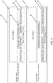
- FIG. 3 illustrates the seat cushion engagement sensor 22 is a closed circuit configuration, with the seat cushion 24 engaging the seat pan support frame 28 and the associated contacts 30 and 32 making electrical contact, and an open circuit configuration, with the seat cushion 24 disengaged from the seat pan support frame 28 and the associated contacts 30 and 32 failing to make electrical contact.
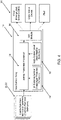
- a controller/processor 34 is in communication with the passenger presence sensor 14, the seat back position sensor 18, and the seat cushion engagement sensor 22 and operable for receiving passenger presence information from the passenger presence sensor 14 via a passenger presence sensor link, seat back position information from the seat back position sensor 18 via a seat back position sensor link, and seat cushion engagement information from the seat cushion engagement sensor 22 via a seat cushion engagement sensor link.
- This passenger presence information, seat back position information, and seat cushion engagement information is collected, analyzed, processed, and displayed to a crew member or the like in an easy to digest textual or graphical format.
- a text message or mobile app alert could be sent to the crew member indicating that a given passenger is (partially or wholly) present or absent, a given seat back is (partially or wholly) reclined or upright, and/or a given seat cushion is (partially or wholly) engaged or disengaged.
- This alert may incorporate an event alarm triggered by a predetermined condition and may take the form of a graphical representation of the passenger compartment of the aircraft including all seats and/or a given seat.
- the controller/processor 34 is optionally coupled to a wireless transmitter 36 that communicates the passenger presence information, seat back position information, and seat cushion engagement information to a crew alert device 38 like a management system, such as a crew management system (CMS), a mobile device used by a given crew member, etc.
- a management system such as a crew management system (CMS)
- CMS crew management system
- dedicated wired links may also be used equally.
- all sensor links can be part of a wireless local area network (WLAN) associated with the seat sensor array 10.
- WLAN wireless local area network
- a server when used, is a digital computer that, in terms of hardware architecture, generally includes a processor, input/output (I/O) interfaces, a network interface, a data store, and memory. It should be appreciated by those of ordinary skill in the art that a practical embodiment of the server may include additional components and suitably configured processing logic to support known or conventional operating features that are not described in detail herein.
- the components are communicatively coupled via a local interface.
- the local interface may be, for example but not limited to, one or more buses or other wired or wireless connections, as is known in the art.
- the local interface may have additional elements, which are omitted for simplicity, such as controllers, buffers (caches), drivers, repeaters, and receivers, among many others, to enable communications. Further, the local interface may include address, control, and/or data connections to enable appropriate communications among the aforementioned components.
- the controller/processor 34 is a hardware device for executing software instructions.
- the controller/processor 34 may be any custom made or commercially available processor, a central processing unit (CPU), an auxiliary processor among several processors associated with the server, a semiconductor-based microprocessor (in the form of a microchip or chip set), or generally any device for executing software instructions.
- the controller/processor 34 is configured to execute software stored within the memory, to communicate data to and from the memory, and to generally control operations of the server pursuant to the software instructions.
- the I/O interfaces may be used to receive user input from and/or for providing system output to one or more devices or components. User input may be provided via, for example, a keyboard, touch pad, and/or a mouse.
- I/O interfaces may include, for example, a serial port, a parallel port, a small computer system interface (SCSI), a serial ATA (SATA), a fibre channel, Infiniband, iSCSI, a PCI Express interface (PCI-x), an infrared (IR) interface, a radio frequency (RF) interface, and/or a universal serial bus (USB) interface.
- SCSI small computer system interface
- SATA serial ATA
- PCI-x PCI Express interface
- IR infrared
- RF radio frequency
- USB universal serial bus
- the network interface may be used to enable the server to communicate on a network, such as the Internet, a wide area network (WAN), a local area network (LAN), and the like, etc.
- the network interface may include, for example, an Ethernet card or adapter (e.g., 10BaseT, Fast Ethernet, Gigabit Ethernet, 10GbE) or a wireless local area network (WLAN) card or adapter (e.g., 802.11a/b/g/n).
- the network interface may include address, control, and/or data connections to enable appropriate communications on the network.
- a data store may be used to store data.
- the data store may include any of volatile memory elements (e.g., random access memory (RAM, such as DRAM, SRAM, SDRAM, and the like)), nonvolatile memory elements (e.g., ROM, hard drive, tape, CDROM, and the like), and combinations thereof.
- the data store may incorporate electronic, magnetic, optical, and/or other types of storage media.
- the data store may be located internal to the server such as, for example, an internal hard drive connected to the local interface in the server.
- the data store may be located external to the server such as, for example, an external hard drive connected to the I/O interfaces (e.g., SCSI or USB connection).
- the data store may be connected to the server through a network, such as, for example, a network attached file server.
- the memory may include any of volatile memory elements (e.g., random access memory (RAM, such as DRAM, SRAM, SDRAM, etc.)), nonvolatile memory elements (e.g., ROM, hard drive, tape, CDROM, etc.), and combinations thereof. Moreover, the memory may incorporate electronic, magnetic, optical, and/or other types of storage media. Note that the memory may have a distributed architecture, where various components are situated remotely from one another, but can be accessed by the controller/processor 34.
- the software in memory may include one or more software programs, each of which includes an ordered listing of executable instructions for implementing logical functions.
- the software in the memory includes a suitable operating system (O/S) and one or more programs.
- O/S operating system
- the operating system essentially controls the execution of other computer programs, such as the one or more programs, and provides scheduling, input-output control, file and data management, memory management, and communication control and related services.
- the one or more programs may be configured to implement the various processes, algorithms, methods, techniques, etc. described herein.
- the mobile device can be a digital device that, in terms of hardware architecture, generally includes a processor, input/output (I/O) interfaces, a radio, a data store, and memory. It should be appreciated by those of ordinary skill in the art that a practical embodiment may include additional components and suitably configured processing logic to support known or conventional operating features that are not described in detail herein.
- the components are communicatively coupled via a local interface.
- the local interface can be, for example but not limited to, one or more buses or other wired or wireless connections, as is known in the art.
- the local interface can have additional elements, which are omitted for simplicity, such as controllers, buffers (caches), drivers, repeaters, and receivers, among many others, to enable communications. Further, the local interface may include address, control, and/or data connections to enable appropriate communications among the aforementioned components.
- the processor is a hardware device for executing software instructions.
- the processor can be any custom made or commercially available processor, a central processing unit (CPU), an auxiliary processor among several processors associated with the memory, a semiconductor-based microprocessor (in the form of a microchip or chip set), or generally any device for executing software instructions.
- the processor is configured to execute software stored within the memory, to communicate data to and from the memory, and to generally control operations of the mobile device pursuant to the software instructions.
- the processor may include a mobile optimized processor such as optimized for power consumption and mobile applications.
- the I/O interfaces can be used to receive user input from and/or for providing system output.
- User input can be provided via, for example, a keypad, a touch screen, a scroll ball, a scroll bar, buttons, bar code scanner, and the like.
- System output can be provided via a display device such as a liquid crystal display (LCD), touch screen, and the like.
- the I/O interfaces can also include, for example, a serial port, a parallel port, a small computer system interface (SCSI), an infrared (IR) interface, a radio frequency (RF) interface, a universal serial bus (USB) interface, and the like.
- the I/O interfaces can include a graphical user interface (GUI) that enables a user to interact with the memory. Additionally, the I/O interfaces may further include an imaging device, i.e. camera, video camera, etc.
- an imaging device i.e. camera, video camera, etc.
- the radio enables wireless communication to an external access device or network.
- Any number of suitable wireless data communication protocols, techniques, or methodologies can be supported by the radio, including, without limitation: RF; IrDA (infrared); Bluetooth; ZigBee (and other variants of the IEEE 802.15 protocol); IEEE 802.11 (any variation); IEEE 802.16 (WiMAX or any other variation); Direct Sequence Spread Spectrum; Frequency Hopping Spread Spectrum; Long Term Evolution (LTE); cellular/wireless/cordless telecommunication protocols (e.g.
- the data store may be used to store data.
- the data store may include any of volatile memory elements (e.g., random access memory (RAM, such as DRAM, SRAM, SDRAM, and the like)), nonvolatile memory elements (e.g., ROM, hard drive, tape, CDROM, and the like), and combinations thereof.
- the data store may incorporate electronic, magnetic, optical, and/or other types of storage media.
- the memory may include any of volatile memory elements (e.g., random access memory (RAM, such as DRAM, SRAM, SDRAM, etc.)), nonvolatile memory elements (e.g., ROM, hard drive, etc.), and combinations thereof. Moreover, the memory may incorporate electronic, magnetic, optical, and/or other types of storage media. Note that the memory may have a distributed architecture, where various components are situated remotely from one another, but can be accessed by the processor.
- the software in memory can include one or more software programs, each of which includes an ordered listing of executable instructions for implementing logical functions.
- the software in the memory includes a suitable operating system (O/S) and programs.
- O/S operating system
- the operating system essentially controls the execution of other computer programs, and provides scheduling, input-output control, file and data management, memory management, and communication control and related services.
- the programs may include various applications, add-ons, etc. configured to provide end user functionality with the mobile device.
- the end user typically uses one or more of the programs along with a network.
- the programs can include an application or "app" which provides various functionality in communication with the seat sensor array 10.
- all housings and memories described herein may be hardened such that components and data may be preserved in the event of a catastrophic occurrence or the like.
- the seat sensor array 10 described herein aides in the onboarding process and allows a flight crew to verify that an aircraft is secured and ready for takeoff or landing, for example. Typically, such identification is performed by visual inspection by the flight crew. This is a labor intensive process and does not ensure that a passenger does not leave his or her seat after the visual inspection is performed, for example. Further, the seat sensor array 10 described herein allows the flight crew to verify that each and every seat back is in an upright position before takeoff or landing, for example. Again, such verification is typically performed by visual inspection by the flight crew. This is a labor intensive process and does not ensure that a passenger does move leave his or her seat back after the visual inspection is performed, for example.
- the seat sensor array 10 described herein allows the flight crew to determine if a seat cushion is dislodged or removed. Such a dislodged seat cushion could indicate the presence of a prohibited object beneath the seat cushion or prevent the seat cushion from functioning as intended during an emergency. Again, such determination is typically performed by visual inspection by the flight crew. This is a labor intensive process and does not ensure that a passenger does dislodge his or her seat cushion after the visual inspection is performed, for example.
Landscapes
- Engineering & Computer Science (AREA)
- Aviation & Aerospace Engineering (AREA)
- Transportation (AREA)
- Mechanical Engineering (AREA)
- Seats For Vehicles (AREA)
Claims (9)
- Sitzanordnung zur Verwendung in einem Transportfahrzeug, wie z. B. einem Flugzeug, wobei die Sitzanordnung umfasst:einen ersten Sitz (16a) mit einer Rückenlehne und einem Sitzkissen;einen zweiten Sitz (16b), wobei der erste Sitz (16a) umfasst:
eine Sensoranordnung (10), umfassend:einen Passagieranwesenheitssensor (14), der dazu betreibbar ist, zu bestimmen, ob ein Passagier auf dem zweiten Sitz (16b) anwesend oder abwesend ist;einen Rückenlehnenpositionssensor (18), der dazu betreibbar ist, zu bestimmen, ob sich eine Rückenlehne (20) des ersten Sitzes (16a) in einer zurückgeneigten oder aufrechten Position befindet; undeine Steuervorrichtung (34), die mit dem Passagieranwesenheitssensor (14) und dem Rückenlehnenpositionssensor (18) in Verbindung steht und zum Empfangen einer Passagieranwesenheitsinformation aus dem Passagieranwesenheitssensor (14) und einer Rückenlehnenpositionsinformation aus dem Rückenlehnenpositionssensor (18) betreibbar ist,dadurch gekennzeichnet, dassdie Steuervorrichtung (34) ferner dazu ausgelegt ist, die Anwesenheit oder Abwesenheit eines Passagiers auf dem zweiten Sitz (16b) basierend auf einem Vergleich eines gemessenen Abstands zu einem Passagieraufnahmeabschnitt des zweiten Sitzes (16b), wenn dieser unbesetzt ist, mit einem gemessenen Abstand zu einem auf dem zweiten Sitz (16b) anwesenden Passagier zu bestimmen, wobei bei Überschreiten eines gegebenen Schwellenwerts ein Passagier als auf dem zweiten Sitz (16b) anwesend gilt, und die Steuervorrichtung (34) ferner dazu ausgelegt ist, die Passagieranwesenheitsinformation an eine Besatzungsmitgliedsvorrichtung (38) zu übermitteln;wobei der Passagieranwesenheitssensor (14) und der Rückenlehnenpositionssensor (18) zusammen in einem Gehäuse (26) vorgesehen sind, das sich in der Rückenlehne (20) des ersten Sitzes (16a) befindet, und der erste Sitz (16a) in einer Reihe vor dem zweiten Sitz (16b) so positioniert ist, dass der im ersten Sitz (16a) untergebrachte Passagieranwesenheitssensor (14) auf den zweiten Sitz (16b) gerichtet ist, um zu bestimmen, ob ein Passagier auf dem zweiten Sitz (16b) anwesend oder abwesend ist. - Sitzanordnung gemäß Anspruch 1, ferner umfassend einen Sitzkisseneinrastsensor (22), der dazu betreibbar ist, zu bestimmen, ob ein Sitzkissen (24) des ersten Sitzes (16a) aus dem Sitz gelöst oder entfernt ist.
- Sitzanordnung gemäß Anspruch 2, wobei die Steuervorrichtung (34) auch mit dem Sitzkisseneinrastsensor (22) in Verbindung steht und auch zum Empfangen einer Sitzkisseneinrastinformation aus dem Sitzkisseneinrastsensor (22) und zum Übermitteln dieser Sitzkisseneinrastinformation an die Besatzungsmitgliedsvorrichtung (38) betreibbar ist.
- Sitzanordnung gemäß Anspruch 2 oder 3, wobei der Sitzkisseneinrastsensor (22) einen elektrischen Schaltkreis umfasst, der unterbrochen ist, wenn das Sitzkissen (24) des ersten Sitzes aus Sitz gelöst oder entfernt ist.
- Sitzanordnung gemäß Anspruch 2, 3 oder 4, wobei der Sitzkisseneinrastsensor (22) in oder um einen Sitzschalentragrahmen (28) angeordnet ist, der das Sitzkissen (24) des ersten Sitzes (16a) trägt.
- Sitzanordnung gemäß einem oder mehreren der Ansprüche 1-5, wobei der Passagieranwesenheitssensor (14) einen elektromagnetischen Strahlensensor umfasst, wobei der elektromagnetische Strahlensensor einen elektromagnetischen Strahl in Richtung des Passagieraufnahmeabschnitts des zweiten Sitzes (16b) projiziert.
- Sitzanordnung gemäß einem oder mehreren der Ansprüche 1-6, wobei der Rückenlehnenpositionssensor (18) einen Gyroskopsensor umfasst, der mit der Rückenlehne (20) des ersten Sitzes (16a) gekoppelt ist.
- Sitzanordnung gemäß einem oder mehreren der Ansprüche 1-7, wobei die Steuervorrichtung (34) mit einem drahtlosen Sender gekoppelt ist, der dazu ausgelegt ist, die Passagieranwesenheitsinformation und die Rückenlehnenpositionsinformation an ein Verwaltungssystem oder an eine durch das Besatzungsmitglied verwendete Mobilvorrichtung zu übermitteln.
- Sitzanordnung gemäß einem oder mehreren der Ansprüche 3-8, wobei die Steuervorrichtung (34) mit einem drahtlosen Sender gekoppelt ist, der dazu ausgelegt ist, die Passagieranwesenheitsinformation, Rückenlehnenpositionsinformation und Sitzkisseneinrastinformation an eines von einem Verwaltungssystem und einer durch das Besatzungsmitglied verwendeten Mobilvorrichtung zu übermitteln.
Applications Claiming Priority (1)
| Application Number | Priority Date | Filing Date | Title |
|---|---|---|---|
| US15/938,438 US10479524B2 (en) | 2018-03-28 | 2018-03-28 | Seat sensor array and controller and seat assembly incorporating same |
Publications (2)
| Publication Number | Publication Date |
|---|---|
| EP3546360A1 EP3546360A1 (de) | 2019-10-02 |
| EP3546360B1 true EP3546360B1 (de) | 2022-07-13 |
Family
ID=66001027
Family Applications (1)
| Application Number | Title | Priority Date | Filing Date |
|---|---|---|---|
| EP19165851.7A Active EP3546360B1 (de) | 2018-03-28 | 2019-03-28 | Sitzsensoranordnung und steuergerät sowie sitzanordnung damit |
Country Status (3)
| Country | Link |
|---|---|
| US (1) | US10479524B2 (de) |
| EP (1) | EP3546360B1 (de) |
| CN (1) | CN110316383B (de) |
Families Citing this family (6)
| Publication number | Priority date | Publication date | Assignee | Title |
|---|---|---|---|---|
| JP7157834B2 (ja) * | 2021-01-29 | 2022-10-20 | 本田技研工業株式会社 | 乗物用シート |
| JP7242723B2 (ja) * | 2021-01-29 | 2023-03-20 | 本田技研工業株式会社 | 乗物用シート |
| EP4063186B1 (de) | 2021-03-25 | 2024-03-13 | Goodrich Lighting Systems GmbH & Co. KG | Flugzeugpassagierserviceeinheit |
| CN114056576A (zh) * | 2021-09-30 | 2022-02-18 | 湖北航宇嘉泰飞机设备有限公司 | 一种航空座椅智能监测系统 |
| CN115959014B (zh) * | 2022-06-21 | 2025-10-24 | 李明 | 一种智能型座椅控制系统和由其构成的电动座椅 |
| US12479595B2 (en) | 2023-10-11 | 2025-11-25 | B/E Aerospace, Inc. | Method to detect objects or obstacles using radio |
Family Cites Families (15)
| Publication number | Priority date | Publication date | Assignee | Title |
|---|---|---|---|---|
| US20070035114A1 (en) * | 1992-05-05 | 2007-02-15 | Automotive Technologies International, Inc. | Device and Method for Deploying a Vehicular Occupant Protection System |
| EP1318043B1 (de) * | 1999-01-27 | 2009-02-25 | The Furukawa Electric Co., Ltd. | Vorrichtung zur Erfassung der Insassen eines Fahrzeuges |
| DE102006030193A1 (de) * | 2006-06-30 | 2008-01-03 | Airbus Deutschland Gmbh | System zum Bestimmen eines Sitzzustands für einen Flugzeugsitz |
| US7878586B2 (en) * | 2007-10-29 | 2011-02-01 | The Boeing Company | System and method for an anticipatory passenger cabin |
| DE102007055088B4 (de) * | 2007-11-16 | 2013-03-07 | Airbus Operations Gmbh | Sitz mit einem Sitzelement, Sitzanordnung und Verfahren zur Überwachung eines Sitzes |
| DE102007055091A1 (de) * | 2007-11-16 | 2009-05-20 | Airbus Deutschland Gmbh | Sitzanordnung in einem Luftfahrzeug |
| US8274383B2 (en) * | 2008-03-31 | 2012-09-25 | The Boeing Company | Methods and systems for sensing activity using energy harvesting devices |
| US8094041B2 (en) * | 2008-03-31 | 2012-01-10 | The Boeing Company | Seat cushion retention and monitoring in an aircraft |
| GB2496452A (en) * | 2011-11-14 | 2013-05-15 | Almec Eas Ltd | Aircraft seat with position and condition sensors |
| WO2013081630A1 (en) * | 2011-12-02 | 2013-06-06 | Kongsberg Automotive, Inc. | Lockout mechanism for foldable head rest |
| GB2507740A (en) * | 2012-11-07 | 2014-05-14 | Trainfx Ltd | A passenger vehicle seat with occupancy detection and validation sensors |
| US9302781B2 (en) * | 2014-02-25 | 2016-04-05 | Astronics Advanced Electronic Systems Corp. | Apparatus and method to monitor the occupancy of seating |
| US10167089B2 (en) * | 2015-11-23 | 2019-01-01 | At&T Mobility Ii Llc | Gateway for aircraft sensor data |
| US20170283086A1 (en) * | 2016-04-04 | 2017-10-05 | B/E Aerospace, Inc. | Aircraft Passenger Activity Monitoring |
| US20170355282A1 (en) * | 2016-06-14 | 2017-12-14 | Lear Corporation | Seat position detection for seat assemblies |
-
2018
- 2018-03-28 US US15/938,438 patent/US10479524B2/en active Active
-
2019
- 2019-03-28 CN CN201910242059.4A patent/CN110316383B/zh active Active
- 2019-03-28 EP EP19165851.7A patent/EP3546360B1/de active Active
Also Published As
| Publication number | Publication date |
|---|---|
| US10479524B2 (en) | 2019-11-19 |
| US20190300198A1 (en) | 2019-10-03 |
| EP3546360A1 (de) | 2019-10-02 |
| CN110316383B (zh) | 2023-03-24 |
| CN110316383A (zh) | 2019-10-11 |
Similar Documents
| Publication | Publication Date | Title |
|---|---|---|
| EP3546360B1 (de) | Sitzsensoranordnung und steuergerät sowie sitzanordnung damit | |
| US9973263B2 (en) | Integrated communication and application system for aircraft | |
| CN110182369B (zh) | 通用乘客座椅系统和数据接口 | |
| US10881357B1 (en) | Systems and methods for monitoring the health of vehicle passengers using camera images | |
| US20140292503A1 (en) | Systems and Methods for Networking of Car Seat Monitoring Systems Utilizing a Central Hub | |
| EP3466018B1 (de) | Systeme und verfahren zur abwendung eines unbefugten zugriffs auf fahrzeugbordnetzwerke | |
| US11100522B2 (en) | Aircraft motion assessment systems and methods | |
| CA2869001C (en) | Integrated communication and application system for aircraft with runway braking condition application | |
| US10906494B1 (en) | Systems and methods for predicting occupant location based on vehicular collision | |
| US11247698B2 (en) | Methods and systems for monitoring rear objects in a vehicle | |
| KR20180110825A (ko) | 차량 내 방치 인원 확인 장치 | |
| JP2021028735A (ja) | 車両走行システム | |
| US20150371458A1 (en) | Mobile computer peripheral | |
| CN110550231B (zh) | 确定交通工具中的乘客座椅的座椅靠背状态的系统和方法 | |
| CN210126502U (zh) | 电子装置以及安全和约束装置 | |
| US11084495B2 (en) | Monitoring apparatus, monitoring method, and program | |
| US11305877B2 (en) | Electronic device and information processing apparatus | |
| US10648962B2 (en) | System and method for preventing cell phone use while driving | |
| KR20130069100A (ko) | 비행 관리 시스템, 비행 관리 장치 및 이의 제어 방법 | |
| JP2022123780A (ja) | 車両用検温装置 | |
| US20260027869A1 (en) | Information processing method | |
| KR20210088935A (ko) | 실시간 헬스케어 시스템 | |
| EP3771237B1 (de) | Drahtloskommunikationsverwaltungsvorrichtung, drahtloskommunikationsverwaltungssystem und drahtloskommunikationsverwaltungsverfahren |
Legal Events
| Date | Code | Title | Description |
|---|---|---|---|
| PUAI | Public reference made under article 153(3) epc to a published international application that has entered the european phase |
Free format text: ORIGINAL CODE: 0009012 |
|
| STAA | Information on the status of an ep patent application or granted ep patent |
Free format text: STATUS: THE APPLICATION HAS BEEN PUBLISHED |
|
| AK | Designated contracting states |
Kind code of ref document: A1 Designated state(s): AL AT BE BG CH CY CZ DE DK EE ES FI FR GB GR HR HU IE IS IT LI LT LU LV MC MK MT NL NO PL PT RO RS SE SI SK SM TR |
|
| AX | Request for extension of the european patent |
Extension state: BA ME |
|
| STAA | Information on the status of an ep patent application or granted ep patent |
Free format text: STATUS: REQUEST FOR EXAMINATION WAS MADE |
|
| 17P | Request for examination filed |
Effective date: 20200331 |
|
| RBV | Designated contracting states (corrected) |
Designated state(s): AL AT BE BG CH CY CZ DE DK EE ES FI FR GB GR HR HU IE IS IT LI LT LU LV MC MK MT NL NO PL PT RO RS SE SI SK SM TR |
|
| STAA | Information on the status of an ep patent application or granted ep patent |
Free format text: STATUS: EXAMINATION IS IN PROGRESS |
|
| 17Q | First examination report despatched |
Effective date: 20200720 |
|
| GRAP | Despatch of communication of intention to grant a patent |
Free format text: ORIGINAL CODE: EPIDOSNIGR1 |
|
| STAA | Information on the status of an ep patent application or granted ep patent |
Free format text: STATUS: GRANT OF PATENT IS INTENDED |
|
| INTG | Intention to grant announced |
Effective date: 20220208 |
|
| GRAS | Grant fee paid |
Free format text: ORIGINAL CODE: EPIDOSNIGR3 |
|
| GRAA | (expected) grant |
Free format text: ORIGINAL CODE: 0009210 |
|
| STAA | Information on the status of an ep patent application or granted ep patent |
Free format text: STATUS: THE PATENT HAS BEEN GRANTED |
|
| AK | Designated contracting states |
Kind code of ref document: B1 Designated state(s): AL AT BE BG CH CY CZ DE DK EE ES FI FR GB GR HR HU IE IS IT LI LT LU LV MC MK MT NL NO PL PT RO RS SE SI SK SM TR |
|
| REG | Reference to a national code |
Ref country code: CH Ref legal event code: EP |
|
| REG | Reference to a national code |
Ref country code: DE Ref legal event code: R096 Ref document number: 602019016879 Country of ref document: DE |
|
| REG | Reference to a national code |
Ref country code: AT Ref legal event code: REF Ref document number: 1504164 Country of ref document: AT Kind code of ref document: T Effective date: 20220815 |
|
| REG | Reference to a national code |
Ref country code: IE Ref legal event code: FG4D |
|
| REG | Reference to a national code |
Ref country code: LT Ref legal event code: MG9D |
|
| REG | Reference to a national code |
Ref country code: NL Ref legal event code: MP Effective date: 20220713 |
|
| PG25 | Lapsed in a contracting state [announced via postgrant information from national office to epo] |
Ref country code: SE Free format text: LAPSE BECAUSE OF FAILURE TO SUBMIT A TRANSLATION OF THE DESCRIPTION OR TO PAY THE FEE WITHIN THE PRESCRIBED TIME-LIMIT Effective date: 20220713 Ref country code: RS Free format text: LAPSE BECAUSE OF FAILURE TO SUBMIT A TRANSLATION OF THE DESCRIPTION OR TO PAY THE FEE WITHIN THE PRESCRIBED TIME-LIMIT Effective date: 20220713 Ref country code: PT Free format text: LAPSE BECAUSE OF FAILURE TO SUBMIT A TRANSLATION OF THE DESCRIPTION OR TO PAY THE FEE WITHIN THE PRESCRIBED TIME-LIMIT Effective date: 20221114 Ref country code: NO Free format text: LAPSE BECAUSE OF FAILURE TO SUBMIT A TRANSLATION OF THE DESCRIPTION OR TO PAY THE FEE WITHIN THE PRESCRIBED TIME-LIMIT Effective date: 20221013 Ref country code: NL Free format text: LAPSE BECAUSE OF FAILURE TO SUBMIT A TRANSLATION OF THE DESCRIPTION OR TO PAY THE FEE WITHIN THE PRESCRIBED TIME-LIMIT Effective date: 20220713 Ref country code: LV Free format text: LAPSE BECAUSE OF FAILURE TO SUBMIT A TRANSLATION OF THE DESCRIPTION OR TO PAY THE FEE WITHIN THE PRESCRIBED TIME-LIMIT Effective date: 20220713 Ref country code: LT Free format text: LAPSE BECAUSE OF FAILURE TO SUBMIT A TRANSLATION OF THE DESCRIPTION OR TO PAY THE FEE WITHIN THE PRESCRIBED TIME-LIMIT Effective date: 20220713 Ref country code: FI Free format text: LAPSE BECAUSE OF FAILURE TO SUBMIT A TRANSLATION OF THE DESCRIPTION OR TO PAY THE FEE WITHIN THE PRESCRIBED TIME-LIMIT Effective date: 20220713 Ref country code: ES Free format text: LAPSE BECAUSE OF FAILURE TO SUBMIT A TRANSLATION OF THE DESCRIPTION OR TO PAY THE FEE WITHIN THE PRESCRIBED TIME-LIMIT Effective date: 20220713 |
|
| REG | Reference to a national code |
Ref country code: AT Ref legal event code: MK05 Ref document number: 1504164 Country of ref document: AT Kind code of ref document: T Effective date: 20220713 |
|
| PG25 | Lapsed in a contracting state [announced via postgrant information from national office to epo] |
Ref country code: PL Free format text: LAPSE BECAUSE OF FAILURE TO SUBMIT A TRANSLATION OF THE DESCRIPTION OR TO PAY THE FEE WITHIN THE PRESCRIBED TIME-LIMIT Effective date: 20220713 Ref country code: IS Free format text: LAPSE BECAUSE OF FAILURE TO SUBMIT A TRANSLATION OF THE DESCRIPTION OR TO PAY THE FEE WITHIN THE PRESCRIBED TIME-LIMIT Effective date: 20221113 Ref country code: HR Free format text: LAPSE BECAUSE OF FAILURE TO SUBMIT A TRANSLATION OF THE DESCRIPTION OR TO PAY THE FEE WITHIN THE PRESCRIBED TIME-LIMIT Effective date: 20220713 Ref country code: GR Free format text: LAPSE BECAUSE OF FAILURE TO SUBMIT A TRANSLATION OF THE DESCRIPTION OR TO PAY THE FEE WITHIN THE PRESCRIBED TIME-LIMIT Effective date: 20221014 |
|
| REG | Reference to a national code |
Ref country code: DE Ref legal event code: R097 Ref document number: 602019016879 Country of ref document: DE |
|
| PG25 | Lapsed in a contracting state [announced via postgrant information from national office to epo] |
Ref country code: SM Free format text: LAPSE BECAUSE OF FAILURE TO SUBMIT A TRANSLATION OF THE DESCRIPTION OR TO PAY THE FEE WITHIN THE PRESCRIBED TIME-LIMIT Effective date: 20220713 Ref country code: RO Free format text: LAPSE BECAUSE OF FAILURE TO SUBMIT A TRANSLATION OF THE DESCRIPTION OR TO PAY THE FEE WITHIN THE PRESCRIBED TIME-LIMIT Effective date: 20220713 Ref country code: DK Free format text: LAPSE BECAUSE OF FAILURE TO SUBMIT A TRANSLATION OF THE DESCRIPTION OR TO PAY THE FEE WITHIN THE PRESCRIBED TIME-LIMIT Effective date: 20220713 Ref country code: CZ Free format text: LAPSE BECAUSE OF FAILURE TO SUBMIT A TRANSLATION OF THE DESCRIPTION OR TO PAY THE FEE WITHIN THE PRESCRIBED TIME-LIMIT Effective date: 20220713 Ref country code: AT Free format text: LAPSE BECAUSE OF FAILURE TO SUBMIT A TRANSLATION OF THE DESCRIPTION OR TO PAY THE FEE WITHIN THE PRESCRIBED TIME-LIMIT Effective date: 20220713 |
|
| PLBE | No opposition filed within time limit |
Free format text: ORIGINAL CODE: 0009261 |
|
| STAA | Information on the status of an ep patent application or granted ep patent |
Free format text: STATUS: NO OPPOSITION FILED WITHIN TIME LIMIT |
|
| PG25 | Lapsed in a contracting state [announced via postgrant information from national office to epo] |
Ref country code: SK Free format text: LAPSE BECAUSE OF FAILURE TO SUBMIT A TRANSLATION OF THE DESCRIPTION OR TO PAY THE FEE WITHIN THE PRESCRIBED TIME-LIMIT Effective date: 20220713 Ref country code: EE Free format text: LAPSE BECAUSE OF FAILURE TO SUBMIT A TRANSLATION OF THE DESCRIPTION OR TO PAY THE FEE WITHIN THE PRESCRIBED TIME-LIMIT Effective date: 20220713 |
|
| 26N | No opposition filed |
Effective date: 20230414 |
|
| PG25 | Lapsed in a contracting state [announced via postgrant information from national office to epo] |
Ref country code: AL Free format text: LAPSE BECAUSE OF FAILURE TO SUBMIT A TRANSLATION OF THE DESCRIPTION OR TO PAY THE FEE WITHIN THE PRESCRIBED TIME-LIMIT Effective date: 20220713 |
|
| P01 | Opt-out of the competence of the unified patent court (upc) registered |
Effective date: 20230608 |
|
| PG25 | Lapsed in a contracting state [announced via postgrant information from national office to epo] |
Ref country code: SI Free format text: LAPSE BECAUSE OF FAILURE TO SUBMIT A TRANSLATION OF THE DESCRIPTION OR TO PAY THE FEE WITHIN THE PRESCRIBED TIME-LIMIT Effective date: 20220713 |
|
| PG25 | Lapsed in a contracting state [announced via postgrant information from national office to epo] |
Ref country code: MC Free format text: LAPSE BECAUSE OF FAILURE TO SUBMIT A TRANSLATION OF THE DESCRIPTION OR TO PAY THE FEE WITHIN THE PRESCRIBED TIME-LIMIT Effective date: 20220713 |
|
| REG | Reference to a national code |
Ref country code: CH Ref legal event code: PL |
|
| REG | Reference to a national code |
Ref country code: BE Ref legal event code: MM Effective date: 20230331 |
|
| PG25 | Lapsed in a contracting state [announced via postgrant information from national office to epo] |
Ref country code: LU Free format text: LAPSE BECAUSE OF NON-PAYMENT OF DUE FEES Effective date: 20230328 |
|
| REG | Reference to a national code |
Ref country code: IE Ref legal event code: MM4A |
|
| PG25 | Lapsed in a contracting state [announced via postgrant information from national office to epo] |
Ref country code: LI Free format text: LAPSE BECAUSE OF NON-PAYMENT OF DUE FEES Effective date: 20230331 Ref country code: IT Free format text: LAPSE BECAUSE OF FAILURE TO SUBMIT A TRANSLATION OF THE DESCRIPTION OR TO PAY THE FEE WITHIN THE PRESCRIBED TIME-LIMIT Effective date: 20220713 Ref country code: IE Free format text: LAPSE BECAUSE OF NON-PAYMENT OF DUE FEES Effective date: 20230328 Ref country code: CH Free format text: LAPSE BECAUSE OF NON-PAYMENT OF DUE FEES Effective date: 20230331 |
|
| PG25 | Lapsed in a contracting state [announced via postgrant information from national office to epo] |
Ref country code: BE Free format text: LAPSE BECAUSE OF NON-PAYMENT OF DUE FEES Effective date: 20230331 |
|
| PG25 | Lapsed in a contracting state [announced via postgrant information from national office to epo] |
Ref country code: BG Free format text: LAPSE BECAUSE OF FAILURE TO SUBMIT A TRANSLATION OF THE DESCRIPTION OR TO PAY THE FEE WITHIN THE PRESCRIBED TIME-LIMIT Effective date: 20220713 |
|
| PG25 | Lapsed in a contracting state [announced via postgrant information from national office to epo] |
Ref country code: BG Free format text: LAPSE BECAUSE OF FAILURE TO SUBMIT A TRANSLATION OF THE DESCRIPTION OR TO PAY THE FEE WITHIN THE PRESCRIBED TIME-LIMIT Effective date: 20220713 |
|
| PG25 | Lapsed in a contracting state [announced via postgrant information from national office to epo] |
Ref country code: CY Free format text: LAPSE BECAUSE OF FAILURE TO SUBMIT A TRANSLATION OF THE DESCRIPTION OR TO PAY THE FEE WITHIN THE PRESCRIBED TIME-LIMIT; INVALID AB INITIO Effective date: 20190328 |
|
| PG25 | Lapsed in a contracting state [announced via postgrant information from national office to epo] |
Ref country code: HU Free format text: LAPSE BECAUSE OF FAILURE TO SUBMIT A TRANSLATION OF THE DESCRIPTION OR TO PAY THE FEE WITHIN THE PRESCRIBED TIME-LIMIT; INVALID AB INITIO Effective date: 20190328 |
|
| PG25 | Lapsed in a contracting state [announced via postgrant information from national office to epo] |
Ref country code: TR Free format text: LAPSE BECAUSE OF FAILURE TO SUBMIT A TRANSLATION OF THE DESCRIPTION OR TO PAY THE FEE WITHIN THE PRESCRIBED TIME-LIMIT Effective date: 20220713 |
|
| PGFP | Annual fee paid to national office [announced via postgrant information from national office to epo] |
Ref country code: GB Payment date: 20260220 Year of fee payment: 8 |
|
| PGFP | Annual fee paid to national office [announced via postgrant information from national office to epo] |
Ref country code: DE Payment date: 20260219 Year of fee payment: 8 |
|
| PGFP | Annual fee paid to national office [announced via postgrant information from national office to epo] |
Ref country code: FR Payment date: 20260220 Year of fee payment: 8 |