EP3546161A1 - Schneidpfosten zur montage an einer schneidvorrichtung und schneidvorrichtung mit einem solchen schneidpfosten - Google Patents
Schneidpfosten zur montage an einer schneidvorrichtung und schneidvorrichtung mit einem solchen schneidpfosten Download PDFInfo
- Publication number
- EP3546161A1 EP3546161A1 EP18164716.5A EP18164716A EP3546161A1 EP 3546161 A1 EP3546161 A1 EP 3546161A1 EP 18164716 A EP18164716 A EP 18164716A EP 3546161 A1 EP3546161 A1 EP 3546161A1
- Authority
- EP
- European Patent Office
- Prior art keywords
- cutting
- post
- blade
- edge
- posts
- Prior art date
- Legal status (The legal status is an assumption and is not a legal conclusion. Google has not performed a legal analysis and makes no representation as to the accuracy of the status listed.)
- Granted
Links
Images


Classifications
-
- B—PERFORMING OPERATIONS; TRANSPORTING
- B26—HAND CUTTING TOOLS; CUTTING; SEVERING
- B26F—PERFORATING; PUNCHING; CUTTING-OUT; STAMPING-OUT; SEVERING BY MEANS OTHER THAN CUTTING
- B26F1/00—Perforating; Punching; Cutting-out; Stamping-out; Apparatus therefor
- B26F1/38—Cutting-out; Stamping-out
- B26F1/44—Cutters therefor; Dies therefor
-
- B—PERFORMING OPERATIONS; TRANSPORTING
- B26—HAND CUTTING TOOLS; CUTTING; SEVERING
- B26D—CUTTING; DETAILS COMMON TO MACHINES FOR PERFORATING, PUNCHING, CUTTING-OUT, STAMPING-OUT OR SEVERING
- B26D1/00—Cutting through work characterised by the nature or movement of the cutting member or particular materials not otherwise provided for; Apparatus or machines therefor; Cutting members therefor
- B26D1/0006—Cutting members therefor
-
- B—PERFORMING OPERATIONS; TRANSPORTING
- B26—HAND CUTTING TOOLS; CUTTING; SEVERING
- B26D—CUTTING; DETAILS COMMON TO MACHINES FOR PERFORATING, PUNCHING, CUTTING-OUT, STAMPING-OUT OR SEVERING
- B26D7/00—Details of apparatus for cutting, cutting-out, stamping-out, punching, perforating, or severing by means other than cutting
- B26D7/26—Means for mounting or adjusting the cutting member; Means for adjusting the stroke of the cutting member
- B26D7/2614—Means for mounting the cutting member
-
- B—PERFORMING OPERATIONS; TRANSPORTING
- B65—CONVEYING; PACKING; STORING; HANDLING THIN OR FILAMENTARY MATERIAL
- B65B—MACHINES, APPARATUS OR DEVICES FOR, OR METHODS OF, PACKAGING ARTICLES OR MATERIALS; UNPACKING
- B65B61/00—Auxiliary devices, not otherwise provided for, for operating on sheets, blanks, webs, binding material, containers or packages
- B65B61/04—Auxiliary devices, not otherwise provided for, for operating on sheets, blanks, webs, binding material, containers or packages for severing webs, or for separating joined packages
- B65B61/06—Auxiliary devices, not otherwise provided for, for operating on sheets, blanks, webs, binding material, containers or packages for severing webs, or for separating joined packages by cutting
-
- B—PERFORMING OPERATIONS; TRANSPORTING
- B26—HAND CUTTING TOOLS; CUTTING; SEVERING
- B26D—CUTTING; DETAILS COMMON TO MACHINES FOR PERFORATING, PUNCHING, CUTTING-OUT, STAMPING-OUT OR SEVERING
- B26D1/00—Cutting through work characterised by the nature or movement of the cutting member or particular materials not otherwise provided for; Apparatus or machines therefor; Cutting members therefor
- B26D1/0006—Cutting members therefor
- B26D2001/0033—Cutting members therefor assembled from multiple blades
-
- B—PERFORMING OPERATIONS; TRANSPORTING
- B26—HAND CUTTING TOOLS; CUTTING; SEVERING
- B26D—CUTTING; DETAILS COMMON TO MACHINES FOR PERFORATING, PUNCHING, CUTTING-OUT, STAMPING-OUT OR SEVERING
- B26D1/00—Cutting through work characterised by the nature or movement of the cutting member or particular materials not otherwise provided for; Apparatus or machines therefor; Cutting members therefor
- B26D1/0006—Cutting members therefor
- B26D2001/0053—Cutting members therefor having a special cutting edge section or blade section
-
- B—PERFORMING OPERATIONS; TRANSPORTING
- B26—HAND CUTTING TOOLS; CUTTING; SEVERING
- B26D—CUTTING; DETAILS COMMON TO MACHINES FOR PERFORATING, PUNCHING, CUTTING-OUT, STAMPING-OUT OR SEVERING
- B26D1/00—Cutting through work characterised by the nature or movement of the cutting member or particular materials not otherwise provided for; Apparatus or machines therefor; Cutting members therefor
- B26D1/0006—Cutting members therefor
- B26D2001/006—Cutting members therefor the cutting blade having a special shape, e.g. a special outline, serrations
-
- B—PERFORMING OPERATIONS; TRANSPORTING
- B26—HAND CUTTING TOOLS; CUTTING; SEVERING
- B26F—PERFORATING; PUNCHING; CUTTING-OUT; STAMPING-OUT; SEVERING BY MEANS OTHER THAN CUTTING
- B26F1/00—Perforating; Punching; Cutting-out; Stamping-out; Apparatus therefor
- B26F1/38—Cutting-out; Stamping-out
- B26F1/44—Cutters therefor; Dies therefor
- B26F2001/4463—Methods and devices for rule setting, fixation, preparing cutting dies
-
- B—PERFORMING OPERATIONS; TRANSPORTING
- B26—HAND CUTTING TOOLS; CUTTING; SEVERING
- B26F—PERFORATING; PUNCHING; CUTTING-OUT; STAMPING-OUT; SEVERING BY MEANS OTHER THAN CUTTING
- B26F1/00—Perforating; Punching; Cutting-out; Stamping-out; Apparatus therefor
- B26F1/38—Cutting-out; Stamping-out
- B26F1/44—Cutters therefor; Dies therefor
- B26F2001/4481—Cutters therefor; Dies therefor having special lateral or edge outlines or special surface shapes, e.g. apertures
Definitions
- the invention relates to a cutting post for mounting on a cutting device and a cutting device with at least one cutting blade and with at least one such cutting post.
- packaging machines are used to shape the packaging from plastic films in several process steps, to fill it with a product and, if appropriate, subsequently to seal it.
- the packages are usually cut out of a large film section.
- cutting devices are provided in the packaging machines.
- Such cutting devices have a cutting contour which specifies the geometry and size of the product packaging to be cut out. Especially with more complex or even angular cutting contours, an arrangement of several cutting blades is necessary in order to map the cutting contour can. In the arrangement of the cutting blade to each other form gaps due to usual manufacturing tolerances between the cutting blades.
- the interruptions in the cutting contour mean that the packages are not cut at the points of impact of the cutting blades, in particular at the corner regions of the cutting contour.
- the disadvantage is formed at the non-cut points unwanted threads. Possibly even tear out the packaging in the appropriate places. Such defects on the packaging lead to a high production waste and thus cause high costs in production.
- the invention has for its object to provide a cutting device, which allows easy assembly of cutting knives at the same time precise cutout of packaging.
- the invention is also based on the object to provide a cutting device that allows easy assembly of cutting knives at the same time precise cutout of packaging.
- the cutting post according to the invention for mounting on a cutting device comprises at least one receptacle for a cutting blade and at least one cutting element arranged at its head end with a cutting edge.
- the cutting post is in addition to at least one cutting blade part of the cutting device according to the invention.
- the at least one cutting blade has a cutting blade edge and is held in the receptacle of the at least one cutting post.
- the cutting blade edge of the cutting blade and the cutting edge of the cutting element of the cutting post form a continuous cutting contour.
- the cutting blade By means of the reception of the cutting post, the cutting blade can be arranged and held in a predefined position relative to the cutting post.
- the cutting post and the cutting blade are arranged to each other so that the cutting edge of the cutting blade with the cutting edge of the cutting element of the cutting post form a continuous cutting contour. Gaps in the cutting contour, in particular between the cutting post and the cutting blade can be avoided. As a result, packages along the entire cutting contour of the cutting device can be completely separated. Uncut portions along the packaging outline that result in the formation of a thread or even tearing of the packaging edges can be avoided. In addition, crossing points and nodal points of a cutting contour can be realized without gaps.
- the cutting posts and blades are individually interchangeable, which greatly simplifies geometric adjustments, maintenance and repairs.
- the cutting blade By provided on the cutting post recording the cutting blade can be easily positioned on the cutting post. In a comparatively simple manner, a continuous cutting contour can be formed during assembly of cutting posts and cutting blades on the cutting device.
- the receptacle for the cutting blade is preferably formed as a groove on a peripheral side of the cutting post, which extends in the direction of the longitudinal axis of the cutting post.
- the cutting post can be pushed during assembly on the cutting blade in the longitudinal direction of the cutting post.
- the cutting blade protrudes into the groove of the cutting post.
- the cutting blade is thus fixed positively in the groove.
- the cutting post supports this in the groove mounted cutting blade against shear forces that may occur during the cutting process, for example.
- the groove of the cutting post allows the juxtaposition of cutting blade and cutting posts, whereby a comparatively low installation costs can be ensured.
- the cutting post preferably has several and in particular three or four receptacles for one cutting blade each.
- the cutting post also comprises at its head end the respective recordings associated cutting elements, each with a cutting edge. If a plurality of cutting blades and a plurality of cutting posts are connected to one another, the cutting posts preferably form the nodal points of the formed cutting contours.
- the arrangement of a plurality of cutting posts and cutting blade different cutting contours can be formed, which can be configured in different geometries and sizes. If, for example, four equidistantly spaced receptacles for cutting blades are provided on cutting posts, square and / or rectangular cutting contours can be formed.
- the cutting blades can be arranged in a honeycomb structure to each other. Since the cutting posts connect as nodes the cutting blade edges of the various cutting blades by means of the cutting edges of the cutting posts to a continuous cutting contour, even with such complex structures a precise cutout of packaging can be ensured.
- a cutting tip tapering in the direction from the foot end to the head end is preferably formed.
- the cutting tip is preferably formed by the cutting edge of the at least one cutting element.
- the cutting edge runs out in the cutting tip.
- the cutting edge of the at least one cutting element preferably includes an angle with a straight line that runs parallel to the longitudinal axis of the cutting post. This angle is open towards the foot of the cutting post and is smaller than 90 °, in particular smaller than 60 ° and in particular about 45 °.
- the packaging film is contacted during the cutting process first by the cutting tip and only then followed by the remaining cutting contour.
- the packaging film is first pierced by the cutting tip and cut out from there along the cutting contour.
- the packaging can be cut out even at low cutting forces, so that the packaging film neither warps nor overstretched.
- the at least one cutting element of the cutting post projecting beyond the receptacle for the cutting blade, starting from the longitudinal axis of the cutting post in the radial direction. If the knife is held in the receptacle of the cutting post, the cutting element of the at least one cutting post and the cutting blade overlap. When assembled, the cutting post and the cutting blade contact each other in the overlap. On the one hand, the overlap acts as a positive hold-down for the cutting blade, so that the cutting post and the cutting blade are precisely positioned in the longitudinal direction of the cutting post to each other. On the other hand, this ensures a seamless transition between the cutting edge of the cutting post and the cutting blade edge of the cutting blade. Thus, the overlap between the cutting post and cutting blade of the fixation of the cutting blade in the longitudinal direction while forming a continuous cutting contour.
- corner post has at least one groove for receiving a cutting blade, but no associated cutting element.
- corner posts can in particular record and support cutting blades, which are provided as edge elements. At such edge regions a continuation of the cutting contour is not necessary. Therefore, it is sufficient to provide the comparatively inexpensive corner posts without cutting elements.
- the cutting device preferably comprises a base plate, wherein a plurality of cutting blades and a plurality of cutting posts are fastened modularly releasably and replaceably on the base plate. Due to the modular design of the cutting contour of cutting blades and cutting posts individual cutting contours can be created from the same basic elements and possibly also changed. If a cutting knife or a cutting post to maintain or even defective, it is sufficient to replace only the affected element of the cutting device against an intact element. A change of the entire cutting device is not necessary. In addition, for example, after a decommissioning of a cutting device whose cutting blade and cutting posts are reused in another cutting device.
- Fig. 1 shows a cutting device according to the invention executed in a perspective view.
- the cutting device 1 is part of a packaging machine, not shown, and serves herein to cut out packages.
- packages are made of plastic film, which is usually provided in the form of film webs.
- the plastic film is deep-drawn in the packaging machine, for example via a deep-drawing process by means of vacuum in a corresponding packaging form, for example in a bag shape.
- the packaging form is filled with the product to be packaged and sealed with a second plastic film.
- one of the last method steps is carried out, namely the removal of the filled packaging from the film web.
- Particularly suitable as packaging materials are water-soluble plastics such as polyvinyl alcohol (PVOH), but also water-insoluble plastics can be used to produce such packages.
- the packages can be used, for example, for detergents or detergents both in powdery and in detergent be used in liquid form. Such packages are also suitable for use in the pharmaceutical sector for the packaging of medicines.
- the cutting device 1 has an upper part 23 and a lower part 24.
- the upper part 23 comprises four cutting posts 2 and four cutting blades 4.
- the cutting posts 2 and the cutting blades 4 are mounted on a base plate, not shown.
- receptacles 11 are formed, on which the cutting blade 4 are held positively.
- At the cutting blades 4 each have a cutting blade edge 15 is formed.
- the cutting posts 2 comprise cutting elements 12, on each of which a cutting edge 13 is formed ( Fig. 5 ).
- the cutting edges 13 of the cutting posts 2 and the cutting blade edges 15 of the cutting blade 4 form a continuous cutting contour 16.
- the cutting blades 4 and the cutting posts 2 are alternately arranged such that the cutting contour 16 has a rectangular shape.
- the lower part 24 comprises a mold plate 17, which has a trough 18.
- the trough 18 serves to form the packaging in one of the upstream process steps of the packaging installation.
- a corresponding packaging is in Fig. 1 shown schematically as a packaging film 5.
- cutting slots 19 are formed, which are arranged in a rectangle around the trough 18 extending and corresponding to the rectangular shape of the cutting contour 16.
- lower part 24 and upper part 23 are moved together.
- the upper part 23 with its cutting contour 16 dips into the cutting slots 19 of the lower part 24 and cuts through the packaging film 5. If the packaging film 5 is cut, upper part 23 and lower part 24 are moved apart again. The cutting posts 2 and the cutting blades 4 are pulled out of the cutting slots 19 of the base 24.
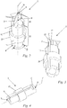
- FIGS. 2 and 3 is the inventively designed cutting post 2 from Fig. 1 shown.
- the cutting post 2 extends along its longitudinal axis 7 from its foot 9 to its head end 8.
- the cutting post 2 has a first portion 25 and a second portion 26.
- the cutting post 2 is formed along the first portion 25, which extends from the root 9 to the second portion 26, as a substantially cylindrical body of revolution.
- the cutting post 2 is formed of four plate-shaped cutting elements 12, each having a cutting edge 13.
- the cutting elements 12 are arranged to each other such that their cutting edges 13 converge in the longitudinal axis 7 together.
- the cutting edges 13 of the cutting elements 12 are inclined relative to the longitudinal axis 7 and run together in a cutting tip 14.
- the cutting edges 13 close with the longitudinal axis 7 of the cutting post 2 an angle ⁇ , which is open towards the foot end 9 of the cutting post 2.
- the angle ⁇ is less than 90 °, in particular less than 60 °, in the preferred embodiment, approximately 45 °.
- the cutting post 2 on a peripheral side 10, on which four receptacles 11 are formed for mounting the cutting blade 4.
- the receptacles 11 are formed as grooves which extend in the direction of the longitudinal axis 7.
- the grooves extend from the foot end 9 of the cutting post 2 up to the cutting element 12.
- the groove is bounded by a first support surface 21 which is formed on the foot end 9 facing side of the cutting element 12.
- the first bearing surface 21 thus forms a vertical stop between the cutting post 2 and the cutting blade 4 in Direction of the longitudinal axis 7.
- a second support surface 22 is formed on the cutting element, which serves starting from the longitudinal axis 7 in the radial direction as a horizontal stop between the cutting post 2 and the cutting blade 4.
- the four receptacles 11 are arranged in the circumferential direction of the cutting post 2 at equal angular intervals.
- the angular distance ⁇ between the respective adjacent receptacles 11 in the FIGS. 2 and 3 shown cutting posts 90 °.
- the cutting elements 12 are aligned at the same angular intervals as the receptacles 11, so that in each case adjacent cutting elements 12 with the cutting edges 13 to each other the angular distance ⁇ in the amount of 90 °.
- the cutting posts 2 in arrangement with the cutting blades 4 mounted on the base plate form a rectangular structure.
- the angular spacing ⁇ of adjacent receptacles 11 and adjacent cutting elements 12 may be different from one another. As a result, for example, diamond or Parallelogrammformen or other structures can be created.
- a corner post 3 is shown.
- the corner post 3 has a receptacle 11, which is formed in the embodiment as a groove.
- the groove extends as in the cutting post 2 along the longitudinal axis 7 'of the Eckpfostens 3.
- the groove extends from the foot end 9 of the Eckpfostens up to a first bearing surface 21, which is formed at the head end 8 of the Eckpfostens 3.
- the corner post can be slid onto the cutting blade 4 for mounting with its groove 11 until it comes into contact with the first bearing surface 21 '.
- the corner posts have no cutting elements 12.
- the corner posts 3 serve only as support of the cutting blade 4, which are arranged at edge regions of a cutting pattern.
- FIGS. 5 to 7 are schematic sectional views of the cutting device according to Fig. 1 shown, which illustrate the cutting process in step images.
- Fig. 5 The upper part 23 and the lower part 24 are still in the starting position. Already in Fig. 6 Upper part 23 and lower part 24 are moved together so far that the cutting tips 14 pierce the packaging film 5.
- the cutting post 2 dives with its second portion 26, namely with its cutting elements 12 in the cutting slots 19 a.
- the packaging film 5 is then cut by the cutting edges 13.
- the cutting blade edges 15 of the cutting elements 4 do not yet protrude into the cutting slots 19.
- Only in Fig. 7 are the upper part 25 and the lower part 26 completely moved together.
- the cutting blades 4 are immersed in the cutting slots 19, and the packaging film 5 is cut out. Subsequently, the upper part 23 and the lower part 24 are moved apart again.
- the cutting blade edges 15 on a corrugation or a serrated edge which extends exclusively in the plane of the respective cutting blade, that has no waveform transverse thereto.
- the cutting forces on the packaging film 5 can be reduced so that stretching or distortion of the packaging film 5 is avoided.
- the cutting lines and thus the outlines of the cut-out packaging are rectilinear.
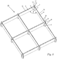
- Fig. 8 is an arrangement of a plurality of cutting posts 2 and a plurality of cutting blades 4 as a variant of the arrangement according to Fig. 1 shown with multiply repeated rectangular sectional contour 16.
- the cutting posts 2 in accordance with the Fig. 2, 3rd in each case four receptacles 11 and four cutting elements 12.
- the mutually adjacent receptacles 11 and the mutually adjacent cutting elements 12 each have an angular distance ⁇ of 90 °. This requires a square, at least rectangular arrangement of the cutting posts 2 and 4 of the cutting blade.
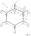
- a further embodiment of an arrangement of a plurality of cutting posts 2 and a plurality of cutting blades 4 is shown, in which case also several corner posts 3 are used in addition.
- the cutting posts 2 here each have three receptacles 11 and three cutting elements 12.
- the mutually adjacent receptacles 11 and the mutually adjacent cutting elements 12 each have an angular distance ⁇ of 120 °. This results in a honeycomb arrangement of the cutting posts 2 and the cutting blade 4 and a corresponding honeycomb pattern. At the edge regions of the arrangement, the cutting blades 4 are held on corner posts 3.
- the patterns after the FIGS. 8 and 9 can be expanded as desired by the addition of additional cutting blade 4, 2 cutting posts and corner posts 3 like a box or even reduced.
- the cutting posts 2 serve as connecting elements of the cutting blade 4.
- the cutting posts not only function as a corner post, but also the function as node or crossing points for the individual cutting lines.
- the cutting posts 2 ensure by the connection of several cutting blade edges 15 with each other via the cutting edges 13 of the cutting elements 12 a everywhere continuous, gap-free cutting contour 16th
Landscapes
- Engineering & Computer Science (AREA)
- Mechanical Engineering (AREA)
- Life Sciences & Earth Sciences (AREA)
- Forests & Forestry (AREA)
- Perforating, Stamping-Out Or Severing By Means Other Than Cutting (AREA)
Abstract
Description
- Die Erfindung betrifft einen Schneidpfosten zur Montage an einer Schneidvorrichtung und eine Schneidvorrichtung mit mindestens einem Schneidmesser und mit mindestens einem solchen Schneidpfosten.
- Zur Herstellung von Produktverpackungen werden Verpackungsmaschinen eingesetzt, um die Verpackungen in mehreren Verfahrensschritten aus Kunststofffolien zu formen, mit einem Produkt zu befüllen und gegebenenfalls anschließend zu versiegeln. In einem der letzten Verfahrensschritte eines solchen Herstellprozesses werden üblicherweise die Verpackungen aus einem großen Folienabschnitt herausgetrennt. Hierfür sind in den Verpackungsmaschinen Schneidvorrichtungen vorgesehen.
- Derartige Schneidvorrichtungen weisen eine Schneidkontur auf, welche die Geometrie und Größe der auszuschneidenden Produktverpackung vorgibt. Insbesondere bei komplexeren oder auch eckigen Schneidkonturen ist eine Anordnung aus mehreren Schneidmessern notwendig, um die Schneidkontur abbilden zu können. Bei der Anordnung der Schneidmesser zueinander bilden sich aufgrund üblicher Fertigungstoleranzen zwischen den Schneidmessern Lücken. Die Unterbrechungen in der Schneidkontur führen dazu, dass die Verpackungen an den Stoßpunkten der Schneidmesser, insbesondere an den Eckbereichen der Schneidkontur, nicht geschnitten werden. Nachteilig bilden sich an den nicht geschnittenen Stellen unerwünschte Fäden. Gegebenenfalls reißen die Verpackungen an den entsprechenden Stellen sogar aus. Derartige Fehlstellen an den Verpackungen führen zu einem hohen Produktionsausschuss und verursachen damit hohe Kosten in der Produktion.
- Zwar sind auch Schneidvorrichtungen bekannt, in welchen zur Vermeidung der genannten Nachteile die Schneidmesser miteinander verschweißt sind. Die Herstellung einer verschweißten Schneidkontur ist jedoch sehr aufwendig und kostenintensiv. Nachteilig ist auch die Wartung einer solchen Schneidvorrichtung. Ist lediglich ein Schneidmesser defekt, müssen dennoch alle miteinander verschweißten Schneidmesser ausgetauscht werden.
- Der Erfindung liegt die Aufgabe zugrunde, eine Schneidvorrichtung anzugeben, welche eine einfache Montage von Schneidmessern bei gleichzeitig präzisem Ausschnitt von Verpackungen ermöglicht.
- Diese Aufgabe wird durch einen Schneidpfosten mit den Merkmalen des Anspruchs 1 gelöst.
- Der Erfindung liegt des Weiteren die Aufgabe zugrunde, eine Schneidvorrichtung zu schaffen, die eine einfache Montage von Schneidmessern bei gleichzeitig präzisem Ausschnitt von Verpackungen ermöglicht.
- Diese Aufgabe wird durch eine Schneidvorrichtung mit den Merkmalen des Anspruchs 8 gelöst.
- Der erfindungsgemäße Schneidpfosten zur Montage an einer Schneidvorrichtung umfasst mindestens eine Aufnahme für ein Schneidmesser und mindestens ein an seinem Kopfende angeordnetes Schneidelement mit einer Schneidkante. Der Schneidpfosten ist neben mindestens einem Schneidmesser Bestandteil der erfindungsgemäßen Schneidvorrichtung. Das mindestens eine Schneidmesser weist eine Schneidmesserkante auf und ist in der Aufnahme des mindestens einen Schneidpfostens gehalten. Die Schneidmesserkante des Schneidmessers und die Schneidkante des Schneidelementes des Schneidpfostens bilden eine durchgehende Schneidkontur.
- Mittels der Aufnahme des Schneidpfostens kann das Schneidmesser in einer vordefinierten Position zum Schneidpfosten angeordnet und gehalten werden.
- Der Schneidpfosten und das Schneidmesser werden dabei so zueinander angeordnet, dass die Schneidkante des Schneidmessers mit der Schneidkante des Schneidelementes des Schneidpfostens eine durchgängige Schneidkontur bilden. Lücken in der Schneidkontur, insbesondere zwischen dem Schneidpfosten und dem Schneidmesser können dabei vermieden werden. Dadurch können Verpackungen entlang der gesamten Schneidkontur der Schneidvorrichtung vollständig ausgetrennt werden. Ungeschnittene Abschnitte entlang des Verpackungsumrisses, die zur Fadenbildung oder sogar zum Ausreißen der Verpackungsränder führen, können dadurch vermieden werden. Außerdem lassen sich Kreuzungs- und Knotenpunkte einer Schneidkontur ohne Lücken realisieren. Die Schneidpfosten und Schneidmesser sind einzeln austauschbar, was geometrische Anpassungen, Wartungen und Reparaturen erheblich vereinfacht.
- Durch die an dem Schneidpfosten vorgesehene Aufnahme kann das Schneidmesser auf einfache Weise an dem Schneidpfosten positioniert werden. Auf vergleichsweise einfache Art und Weise kann bei der Montage von Schneidpfosten und Schneidmesser an der Schneidvorrichtung eine durchgängige Schneidkontur gebildet werden.
- Die Aufnahme für das Schneidmesser ist bevorzugt als Nut an einer Umfangsseite des Schneidpfostens ausgebildet, welche in Richtung der Längsachse des Schneidpfostens verläuft. Durch die Nut im Schneidpfosten kann der Schneidpfosten bei der Montage auf das Schneidmesser in Längsrichtung des Schneidpfostens aufgeschoben werden. Dabei ragt das Schneidmesser in die Nut des Schneidpfostens. Das Schneidmesser ist somit in der Nut formschlüssig fixiert. Der Schneidpfosten stützt das in der Nut montierte Schneidmesser gegen Querkräfte ab, die beispielsweise während des Schneidvorganges auftreten können. Zudem ermöglicht die Nut des Schneidpfostens das Aufeinanderstecken von Schneidmesser und Schneidpfosten, wodurch ein vergleichsweise geringer Montageaufwand gewährleistet werden kann.
- Bevorzugt weist der Schneidpfosten mehrere und insbesondere drei oder vier Aufnahmen für je ein Schneidmesser auf. Vorteilhaft umfasst der Schneidpfosten außerdem an seinem Kopfende den jeweiligen Aufnahmen zugeordnete Schneidelemente mit je einer Schneidkante. Sind mehrere Schneidmesser und mehrere Schneidpfosten miteinander verbunden, bilden die Schneidpfosten vorzugsweise die Knotenpunkte der gebildeten Schneidkonturen. Durch die Anordnung mehrerer Schneidpfosten und Schneidmesser können verschiedene Schneidkonturen gebildet werden, die in unterschiedlichen Geometrien und Größen ausgestaltet werden sein können. Sind an Schneidpfosten beispielsweise vier in gleichem Winkelabstand zueinander angeordnete Aufnahmen für Schneidmesser vorgesehen, können quadratische und/oder rechteckige Schneidkonturen gebildet werden. Sind beispielsweise lediglich drei Aufnahmen vorgesehen, so können die Schneidmesser in einer wabenförmigen Struktur zueinander angeordnet werden. Da die Schneidpfosten als Knotenpunkte die Schneidmesserkanten der verschiedenen Schneidmesser mittels der Schneidkanten der Schneidpfosten zu einer durchgängigen Schneidkontur verbinden, kann auch bei derart komplexen Strukturen ein präziser Ausschnitt von Verpackungen gewährleistet werden.
- An dem Kopfende des Schneidpfostens ist bevorzugt eine in Richtung vom Fußende zum Kopfende zulaufende Schneidspitze ausgebildet. Die Schneidspitze wird vorzugsweise durch die Schneidkante des mindestens einen Schneidelementes gebildet. Dabei läuft die Schneidkante in der Schneidspitze aus. Die Schneidkante des mindestens einen Schneidelementes schließt vorzugsweise mit einer Geraden, die parallel zur Längsachse des Schneidpfostens verläuft, einen Winkel ein. Dieser Winkel ist zum Fußende des Schneidpfostens hin geöffnet und ist kleiner als 90°, insbesondere kleiner als 60° und insbesondere etwa 45°.
- Folglich wird die Verpackungsfolie während des Schneidvorganges zuerst von der Schneidspitze und erst dann gefolgt von der restlichen Schneidkontur kontaktiert. Dadurch wird die Verpackungsfolie durch die Schneidspitze zuerst angestochen und von dort ausgehend entlang der Schneidkontur ausgeschnitten. Durch das Anstechen der Folie kann die Verpackung bereits bei geringen Schnittkräften ausgeschnitten werden, so dass sich die Verpackungsfolie weder verzieht noch überdehnt.
- Es ist vorteilhaft vorgesehen, dass das mindestens eine Schneidelement des Schneidpfostens die Aufnahme für das Schneidmesser ausgehend von der Längsachse des Schneidpfostens in radialer Richtung überragt. Ist das Messer in der Aufnahme des Schneidpfostens gehalten, überlappen sich das Schneidelement des mindestens einen Schneidpfostens und das Schneidmesser. In montiertem Zustand kontaktieren sich der Schneidpfosten und das Schneidmesser in der Überlappung. Einerseits wirkt die Überlappung als formschlüssiger Niederhalter für das Schneidmesser, so dass der Schneidpfosten und das Schneidmesser in Längsrichtung des Schneidpfostens zueinander präzise positioniert sind. Andererseits wird dadurch ein nahtloser Übergang zwischen der Schneidkante des Schneidpfostens und der Schneidmesserkante des Schneidmessers gewährleistet. So dient die Überlappung zwischen Schneidpfosten und Schneidmesser der Fixierung des Schneidmessers in Längsrichtung bei gleichzeitiger Ausbildung einer durchgängigen Schneidkontur.
- Ein weiterer Bestandteil der Schneidvorrichtung ist vorteilhaft mindestens ein Eckpfosten. Der Eckpfosten weist mindestens eine Nut zur Aufnahme eines Schneidmessers auf, jedoch kein zugeordnetes Schneidelement. Derartige Eckpfosten können insbesondere Schneidmesser, die als Randelemente vorgesehen sind, aufnehmen und diese stützen. An derartigen Randbereichen ist eine Fortführung der Schneidkontur nicht notwendig. Daher ist es ausreichend, die vergleichsweise kostengünstigen Eckpfosten ohne Schneidelemente vorzusehen.
- Die Schneidvorrichtung umfasst vorzugsweise eine Grundplatte, wobei mehrere Schneidmesser und mehrere Schneidpfosten baukastenartig lösbar und austauschbar auf der Grundplatte befestigt sind. Durch die baukastenartige Erstellung der Schneidkontur aus Schneidmessern und Schneidpfosten können individuelle Schneidkonturen aus den gleichen Grundelementen erstellt und ggf. auch geändert werden. Ist ein Schneidmesser oder ein Schneidpfosten zu warten oder gar defekt, ist es ausreichend, lediglich das betroffene Element der Schneidvorrichtung gegen ein intaktes Element auszutauschen. Ein Wechsel der gesamten Schneidvorrichtung ist nicht notwendig. Zudem können beispielsweise nach einer Stilllegung einer Schneidvorrichtung deren Schneidmesser und Schneidpfosten in einer anderen Schneidvorrichtung wiederverwendet werden.
- Ausführungsbeispiele der Erfindung werden im Folgenden anhand der Zeichnung erläutert. Es zeigen:
- Fig. 1
- in einer perspektivischen Darstellung eine erfindungsgemäße Schneidvorrichtung mit Schneidmessern und mit Schneidpfosten,
- Fig. 2
- in einer perspektivischen Darstellung einen erfindungsgemäßen Schneidpfosten nach
Fig. 1 mit Einzelheiten zu dessen geometrischer Ausgestaltung, - Fig. 3
- in einer perspektivischen Darstellung von unten den Schneidpfosten nach
Fig. 2 , - Fig. 4
- in einer perspektivischen Darstellung eine als Eckpfosten ausgeführte Variante des Schneidpfostens nach den vorhergehenden Figuren, jedoch ohne Schneidkanten,
- Fig. 5
- in einer perspektivischen, schematischen Schnittdarstellung die Schneidvorrichtung nach
Fig. 1 vor dem Kontakt mit der zu schneidenden Folie, - Fig. 6
- die Anordnung nach
Fig. 5 mit in die Folie eingestochenen Schneidspitzen der Schneidpfosten, - Fig. 7
- die Anordnung nach den
Fig. 5, 6 mit weiter abgesenkten, die Folie durchtrennenden Schneidmessern, - Fig. 8
- in einer perspektivischen Darstellung eine Ausführungsvariante der Anordnung nach den
Fig. 1 bis 7 mit einer Schneidkontur in einer mehrfachen Rechteckstruktur, - Fig. 9
- in einer perspektivischen Darstellung eine weitere Ausführungsvariante mit einer Schneidkontur in einer Wabenstruktur und mit Eckpfosten nach
Fig. 4 . -
Fig. 1 zeigt eine erfindungsgemäß ausgeführte Schneidvorrichtung in perspektivischer Ansicht. Die Schneidvorrichtung 1 ist Teil einer nicht gezeigten Verpackungsmaschine und dient hierin dem Ausschneiden von Verpackungen. Derartige Verpackungen sind aus Kunststofffolie hergestellt, die üblicherweise in Form von Folienbahnen bereitgestellt wird. Die Kunststofffolie wird in der Verpackungsmaschine beispielsweise über ein Tiefziehverfahren mittels Vakuum in eine entsprechende Verpackungsform, beispielsweise in eine Beutelform, tiefgezogen. Danach wird die Verpackungsform mit dem zu verpackenden Produkt befüllt und mit einer zweiten Kunststofffolie versiegelt. Mit Hilfe der Schneidvorrichtung 1 wird einer der letzten Verfahrensschritte durchgeführt, nämlich das Austrennen der befüllten Verpackung aus der Folienbahn. Als Verpackungsmaterialien eignen sich besonders wasserlösliche Kunststoffe wie Polyvinylalkohol (PVOH), aber auch wasserunlösliche Kunststoffe können zur Herstellung derartiger Verpackungen verwendet werden. Die Verpackungen können beispielsweise für Reinigungs- oder Waschmittel sowohl in pulvriger als auch in flüssiger Form verwendet werden. Derartige Verpackungen eignen sich ebenfalls für den Einsatz im Pharmaziebereich zur Verpackung von Arzneimitteln. - Die Schneidvorrichtung 1 weist ein Oberteil 23 und ein Unterteil 24 auf. In dem in
Fig. 1 gezeigten Ausführungsbeispiel umfasst das Oberteil 23 vier Schneidpfosten 2 und vier Schneidmesser 4. Die Schneidpfosten 2 und die Schneidmesser 4 sind auf einer nicht dargestellten Grundplatte montiert. An den Schneidpfosten 2 sind Aufnahmen 11 ausgebildet, an welchen die Schneidmesser 4 formschlüssig gehalten sind. An den Schneidmessern 4 ist jeweils eine Schneidmesserkante 15 ausgebildet. Die Schneidpfosten 2 umfassen Schneidelemente 12, an welchen jeweils eine Schneidkante 13 angeformt ist (Fig. 5 ). Die Schneidkanten 13 der Schneidpfosten 2 und die Schneidmesserkanten 15 der Schneidmesser 4 bilden eine durchgängige Schneidkontur 16. Im Ausführungsbeispiel gemäßFigur 1 sind die Schneidmesser 4 und die Schneidpfosten 2 im Wechsel derart zueinander angeordnet, dass die Schneidkontur 16 eine Rechteckform aufweist. - Das Unterteil 24 umfasst eine Formplatte 17, welche eine Mulde 18 aufweist. Die Mulde 18 dient zur Formung der Verpackung in einem der vorgelagerten Prozessschritte der Verpackungsanlage. Eine entsprechende Verpackung ist in
Fig. 1 schematisch als Verpackungsfolie 5 dargestellt. In der Formplatte 17 sind Schneidschlitze 19 ausgebildet, die in einem Rechteck um die Mulde 18 verlaufend und korrespondierend zur Rechteckform der Schneidkontur 16 angeordnet sind. - Um die Verpackungsfolie 5 entsprechend der Schneidkontur 16 des Oberteils 23 zuzuschneiden, werden Unterteil 24 und Oberteil 23 zusammengefahren. Dabei taucht das Oberteil 23 mit seiner Schneidkontur 16 in die Schneidschlitze 19 des Unterteils 24 ein und schneidet durch die Verpackungsfolie 5 hindurch. Ist die Verpackungsfolie 5 zugeschnitten, werden Oberteil 23 und Unterteil 24 wieder auseinandergefahren. Die Schneidpfosten 2 und die Schneidmesser 4 werden aus den Schneidschlitzen 19 des Unterteils 24 herausgezogen.
- In den
Figuren 2 und 3 ist der erfindungsgemäß ausgeführte Schneidpfosten 2 ausFig. 1 gezeigt. Der Schneidpfosten 2 erstreckt sich entlang seiner Längsachse 7 von seinem Fußende 9 bis hin zu seinem Kopfende 8. - Der Schneidpfosten 2 besitzt einen ersten Abschnitt 25 und einen zweiten Abschnitt 26. Der Schneidpfosten 2 ist entlang des ersten Abschnittes 25, welcher sich vom Fußende 9 bis zum zweiten Abschnitt 26 erstreckt, als ein im Wesentlichen zylindrischer Rotationskörper ausgebildet. Entlang des zweiten Abschnittes 26, welcher sich vom ersten Abschnitt 25 bis hin zum Kopfende 8 erstreckt, ist der Schneidpfosten 2 aus vier plattenförmigen Schneidelementen 12 mit jeweils einer Schneidkante 13 gebildet. Die Schneidelemente 12 sind derart zueinander angeordnet, dass deren Schneidkanten 13 in der Längsachse 7 gemeinsam zulaufen.
- Die Schneidkanten 13 der Schneidelemente 12 sind gegenüber der Längsachse 7 geneigt und laufen gemeinsam in einer Schneidspitze 14 aus. Die Schneidkanten 13 schließen mit der Längsachse 7 des Schneidpfostens 2 einen Winkel α ein, der zum Fußende 9 des Schneidpfostens 2 hin geöffnet ist. Der Winkel α ist kleiner als 90°, insbesondere kleiner als 60°, im bevorzugten Ausführungsbeispiel in etwa 45°.
- Wie in den
Figuren 2 und 3 gezeigt, weist der Schneidpfosten 2 eine Umfangsseite 10 auf, an welcher vier Aufnahmen 11 zur Montage der Schneidmesser 4 ausgebildet sind. In dem bevorzugten Ausführungsbeispiel sind die Aufnahmen 11 als Nuten ausgebildet, die in Richtung der Längsachse 7 verlaufen. Dabei erstrecken sich die Nuten vom Fußende 9 des Schneidpfostens 2 bis hin zum Schneidelement 12. Die Nut wird durch eine erste Auflagefläche 21 begrenzt, die auf der dem Fußende 9 zugewandten Seite des Schneidelementes 12 ausgebildet ist. Beim Montieren des Schneidpfostens 2 auf das Schneidmesser 4 kann der Schneidpfosten 2 an seiner Nut auf das Schneidmesser 4 aufgeschoben werden, bis der Schneidpfosten 2 mit seiner ersten Auflagefläche 21 an dem Schneidmesser 4 zur Anlage kommt. Die erste Auflagefläche 21 bildet demnach einen Vertikalanschlag zwischen dem Schneidpfosten 2 und dem Schneidmesser 4 in Richtung der Längsachse 7. Zudem ist an dem Schneidelement eine zweite Auflagefläche 22 ausgebildet, welche ausgehend von der Längsachse 7 in radialer Richtung als Horizontalanschlag zwischen dem Schneidpfosten 2 und dem Schneidmesser 4 dient. - Die vier Aufnahmen 11 sind in Umfangsrichtung des Schneidpfostens 2 in gleichmäßigen Winkelabständen angeordnet. Damit beträgt der Winkelabstand β zwischen den jeweils benachbarten Aufnahmen 11 der in den
Figuren 2 und 3 gezeigten Schneidpfosten 90°. Die Schneidelemente 12 sind in den gleichen Winkelabständen wie die Aufnahmen 11 ausgerichtet, so dass jeweils benachbarte Schneidelemente 12 mit den Schneidkanten 13 zueinander den Winkelabstand β in Höhe von 90° aufweisen. - Dadurch bilden die Schneidpfosten 2 in Anordnung mit den Schneidmessern 4 auf der Grundplatte montiert eine Rechteckstruktur. In einer nicht gezeigten alternativen Ausführungsvariante der Schneidvorrichtung 1 kann der Winkelabstand β benachbarter Aufnahmen 11 sowie benachbarter Schneidelemente 12 zueinander verschieden sein. Dadurch können beispielsweise Rauten- oder Parallelogrammformen oder andere Strukturen erstellt werden.
- In
Fig. 4 ist ein Eckpfosten 3 gezeigt. Der Eckpfosten 3 weist eine Aufnahme 11 auf, welche im Ausführungsbeispiel als eine Nut ausgebildet ist. Die Nut verläuft wie beim Schneidpfosten 2 entlang der Längsachse 7' des Eckpfostens 3. Dabei erstreckt sich die Nut vom Fußende 9 des Eckpfostens bis hin zu einer ersten Auflagefläche 21, die am Kopfende 8 des Eckpfostens 3 ausgebildet ist. Wie auch der Schneidpfosten 2 kann der Eckpfosten zur Montage mit seiner Nut 11 auf das Schneidmesser 4 aufgeschoben werden, bis dieses an der ersten Auflagefläche 21' zur Anlage kommt. Die Eckpfosten weisen keine Schneidelemente 12 auf. Die Eckpfosten 3 dienen lediglich als Stützung der Schneidmesser 4, die an Randbereichen eines Schneidmusters angeordnet sind. - In den
Figuren 5 bis 7 sind schematische Schnittdarstellungen der Schneidvorrichtung gemäßFig. 1 gezeigt, die den Schneidvorgang in Schrittbildern veranschaulichen. InFig. 5 befinden sich das Oberteil 23 und das Unterteil 24 noch in der Ausgangslage. Bereits inFig. 6 sind Oberteil 23 und Unterteil 24 soweit zusammengefahren, dass die Schneidspitzen 14 die Verpackungsfolie 5 durchstechen. Der Schneidpfosten 2 taucht mit seinem zweiten Abschnitt 26, nämlich mit seinen Schneidelementen 12 in die Schneidschlitze 19 ein. Die Verpackungsfolie 5 wird anschließend durch die Schneidkanten 13 eingeschnitten. Die Schneidmesserkanten 15 der Schneidelemente 4 ragen noch nicht in die Schneidschlitze 19. Erst inFig. 7 sind das Oberteil 25 und das Unterteil 26 vollständig zusammengefahren. Die Schneidmesser 4 sind in die Schneidschlitze 19 eingetaucht, und die Verpackungsfolie 5 ist ausgeschnitten. Anschließend werden das Oberteil 23 und das Unterteil 24 wieder auseinandergefahren. - In dem Ausführungsbeispiel gemäß der Schneidvorrichtung nach
Fig. 1 weisen die Schneidmesserkanten 15 eine Riffelung bzw. einen Wellenschliff auf, der sich ausschließlich in der Ebene des jeweiligen Schneidmessers erstreckt, also keine Wellenform quer dazu aufweist. Dadurch können die Schnittkräfte an der Verpackungsfolie 5 reduziert werden, so dass ein Dehnen oder ein Verzug der Verpackungsfolie 5 vermieden wird. Gleichzeitig sind die Schnittlinien und damit die Umrisse der ausgeschnittenen Verpackung geradlinig ausgebildet. - In
Fig. 8 ist eine Anordnung aus mehreren Schneidpfosten 2 und mehreren Schneidmessern 4 als Variante der Anordnung nachFig. 1 mit mehrfach sich wiederholender rechteckiger Schnittkontur 16 gezeigt. Die Schneidpfosten 2 weisen in Übereinstimmung mit denFig. 2, 3 jeweils vier Aufnahmen 11 und vier Schneidelemente 12 auf. Die zueinander benachbarten Aufnahmen 11 und die zueinander benachbarten Schneidelemente 12 weisen jeweils einen Winkelabstand β von 90° auf. Dies bedingt eine quadratische, zumindest rechteckige Anordnung der Schneidpfosten 2 und der Schneidmesser 4. - In
Fig. 9 ist ein weiteres Ausführungsbeispiel einer Anordnung mehrerer Schneidpfosten 2 und mehrerer Schneidmesser 4 gezeigt, wobei hier zusätzlich auch mehrere Eckpfosten 3 zum Einsatz kommen. Die Schneidpfosten 2 weisen hier jeweils drei Aufnahmen 11 und drei Schneidelemente 12 auf. Die zueinander benachbarten Aufnahmen 11 und die zueinander benachbarten Schneidelemente 12 weisen jeweils einen Winkelabstand β von 120° auf. Daraus resultiert eine wabenförmige Anordnung der Schneidpfosten 2 und der Schneidmesser 4 und ein entsprechend wabenförmiges Schnittmuster. An den Randbereichen der Anordnung sind die Schneidmesser 4 an Eckpfosten 3 gehalten. - Die Schnittmuster nach den
Figuren 8 und9 können nach Belieben durch den Anbau zusätzlicher Schneidmesser 4, Schneidpfosten 2 und Eckpfosten 3 baukastenartig erweitert oder auch reduziert werden. Die Schneidpfosten 2 dienen als Verbindungselemente der Schneidmesser 4. In Ergänzung zur Ausführungsform nachFig. 2 üben hier die Schneidpfosten nicht nur die Funktion als Eckpfosten, sondern auch die Funktion als Knoten- bzw. Kreuzungspunkte für die einzelnen Schneidlinien aus. Dabei gewährleisten die Schneidpfosten 2 durch die Verbindung von mehreren Schneidmesserkanten 15 miteinander über die Schneidkanten 13 der Schneidelemente 12 eine überall durchgängige, lückenfreie Schneidkontur 16.
Claims (13)
- Schneidpfosten zur Montage an einer Schneidvorrichtung,
wobei sich der Schneidpfosten (2) entlang einer Längsachse (7) erstreckt und ein Kopfende (8) sowie ein Fußende (9) umfasst, wobei der Schneidpfosten (2) mindestens eine Aufnahme (11) für ein Schneidmesser (4) und mindestens ein am Kopfende (8) angeordnetes Schneidelement (12) mit einer Schneidkante (13) umfasst. - Schneidpfosten nach Anspruch 1,
dadurch gekennzeichnet, dass die Aufnahme (11) für das Schneidmesser als Nut an einer Umfangsseite (10) des Schneidpfostens (2) ausgebildet ist, welche in Richtung der Längsachse (7) des Schneidpfostens (2) verläuft. - Schneidpfosten nach Anspruch 1 oder 2,
dadurch gekennzeichnet, dass der Schneidpfosten (2) mehrere und insbesondere drei oder vier Aufnahmen (11) für je ein Schneidmesser (4) aufweist, und dass der Schneidpfosten (2) außerdem an seinem Kopfende (8) den jeweiligen Aufnahmen (11) zugeordnete Schneidelemente (12) mit je einer Schneidkante (13) umfasst. - Schneidpfosten nach einem der Ansprüche 1 bis 3,
dadurch gekennzeichnet, dass an dem Kopfende (8) des Schneidpfostens (2) eine in Richtung vom Fußende (9) zum Kopfende (8) zulaufende Schneidspitze (14) ausgebildet ist. - Schneidpfosten nach Anspruch 4,
dadurch gekennzeichnet, dass die Schneidkante (13) des mindestens einen Schneidelementes (12) in der Schneidspitze (14) ausläuft. - Schneidpfosten nach einem der Ansprüche 1 bis 5,
dadurch gekennzeichnet, dass die Schneidkante (13) des mindestens einen Schneidelementes (12) mit einer Geraden, die parallel zur Längsachse (7) des Schneidpfostens (2) verläuft, einen Winkel (α) einschließt, wobei der Winkel (α) zum Fußende (9) des Schneidpfostens (2) hin geöffnet ist, und wobei der Winkel (α) kleiner als 90°, insbesondere kleiner 60° ist, und insbesondere etwa 45° beträgt. - Schneidpfosten nach einem der Ansprüche 1 bis 6,
dadurch gekennzeichnet, dass das mindestens eine Schneidelement (12) die Aufnahme (11) für das Schneidmesser (4) ausgehend von der Längsachse (7) des Schneidpfostens (2) in radialer Richtung überragt. - Schneidvorrichtung mit mindestens einem Schneidmesser (4) und mit mindestens einem Schneidpfosten (2) nach einem der Ansprüche 1 bis 7, wobei das mindestens eine Schneidmesser (4) eine Schneidmesserkante (15) aufweist und in der Aufnahme (2) des mindestens einen Schneidpfostens (2) gehalten ist, wobei die Schneidmesserkante (15) des Schneidmessers (4) und die Schneidmesserkante (13) des Schneidelementes (12) des Schneidpfostens (2) eine durchgehende Schneidkontur (16) bilden.
- Schneidvorrichtung nach Anspruch 8,
dadurch gekennzeichnet, dass die Aufnahme (11) als Nut ausgebildet ist, und dass das mindestens eine Schneidmesser (4) in die Nut des mindestens einen Schneidpfostens (2) ragt. - Schneidvorrichtung nach Anspruch 8 oder 9,
dadurch gekennzeichnet, dass das Schneidelement (12) des mindestens einen Schneidpfostens (2) und das Schneidmesser (4) sich überlappen. - Schneidvorrichtung nach einem der Ansprüche 8 bis 10,
dadurch gekennzeichnet, dass die Schneidvorrichtung (1) mindestens einen Eckpfosten (3) umfasst, wobei der Eckpfosten (3) mindestens eine Nut (11) zur Aufnahme eines Schneidmessers (4) und kein zugeordnetes Schneidelement (12) aufweist. - Schneidvorrichtung nach einem der Ansprüche 8 bis 11,
dadurch gekennzeichnet, dass mehrere Schneidmesser (4) und mehrere Schneidpfosten (2) derart miteinander verbunden sind, dass die Schneidpfosten (2) Knotenpunkte von Schneidkonturen (16) bilden. - Schneidvorrichtung nach einem der Ansprüche 8 bis 12,
dadurch gekennzeichnet, dass die Schneidvorrichtung (1) eine Grundplatte umfasst, wobei mehrere Schneidmesser (4) und mehrere Schneidpfosten (2) baukastenartig lösbar und austauschbar auf der Grundplatte befestigt sind.
Priority Applications (4)
| Application Number | Priority Date | Filing Date | Title |
|---|---|---|---|
| EP18164716.5A EP3546161B1 (de) | 2018-03-28 | 2018-03-28 | Schneidpfosten zur montage an einer schneidvorrichtung und schneidvorrichtung mit einem solchen schneidpfosten |
| PL18164716.5T PL3546161T3 (pl) | 2018-03-28 | 2018-03-28 | Słupek tnący do zamontowania w urządzeniu tnącym i urządzenie tnące z takim słupkiem tnącym |
| US16/360,845 US10850420B2 (en) | 2018-03-28 | 2019-03-21 | Cutting post for mounting on a cutting apparatus and cutting apparatus having such a cutting post |
| CN201910243494.9A CN110315593B (zh) | 2018-03-28 | 2019-03-28 | 用于安装在切割装置上的切割柱和具有这种切割柱的切割装置 |
Applications Claiming Priority (1)
| Application Number | Priority Date | Filing Date | Title |
|---|---|---|---|
| EP18164716.5A EP3546161B1 (de) | 2018-03-28 | 2018-03-28 | Schneidpfosten zur montage an einer schneidvorrichtung und schneidvorrichtung mit einem solchen schneidpfosten |
Publications (2)
| Publication Number | Publication Date |
|---|---|
| EP3546161A1 true EP3546161A1 (de) | 2019-10-02 |
| EP3546161B1 EP3546161B1 (de) | 2022-11-23 |
Family
ID=61868190
Family Applications (1)
| Application Number | Title | Priority Date | Filing Date |
|---|---|---|---|
| EP18164716.5A Active EP3546161B1 (de) | 2018-03-28 | 2018-03-28 | Schneidpfosten zur montage an einer schneidvorrichtung und schneidvorrichtung mit einem solchen schneidpfosten |
Country Status (4)
| Country | Link |
|---|---|
| US (1) | US10850420B2 (de) |
| EP (1) | EP3546161B1 (de) |
| CN (1) | CN110315593B (de) |
| PL (1) | PL3546161T3 (de) |
Families Citing this family (1)
| Publication number | Priority date | Publication date | Assignee | Title |
|---|---|---|---|---|
| CN111673804B (zh) * | 2020-07-20 | 2021-07-06 | 常州纳捷机电科技有限公司 | 一种坚硬板材的平刃切割方法 |
Citations (3)
| Publication number | Priority date | Publication date | Assignee | Title |
|---|---|---|---|---|
| US3263547A (en) * | 1964-08-14 | 1966-08-02 | Bernal Tool & Machine Co | Steel rule cutting die |
| JPS5545483U (de) * | 1978-09-20 | 1980-03-25 | ||
| EP2842704A1 (de) * | 2013-08-30 | 2015-03-04 | Totani Corporation | Kunststofffolienstanzvorrichtung |
Family Cites Families (4)
| Publication number | Priority date | Publication date | Assignee | Title |
|---|---|---|---|---|
| US6523448B1 (en) * | 2000-09-22 | 2003-02-25 | Long Chang | Adaptable hybrid module die board |
| US7073260B2 (en) * | 2004-08-03 | 2006-07-11 | Jensen Raliegh J | Knife assembly |
| JP5545483B2 (ja) * | 2010-08-18 | 2014-07-09 | 株式会社村田製作所 | 複合電子部品の製造方法 |
| CN203293251U (zh) * | 2013-06-27 | 2013-11-20 | 苏娇吟 | 一种切橙器 |
-
2018
- 2018-03-28 PL PL18164716.5T patent/PL3546161T3/pl unknown
- 2018-03-28 EP EP18164716.5A patent/EP3546161B1/de active Active
-
2019
- 2019-03-21 US US16/360,845 patent/US10850420B2/en active Active
- 2019-03-28 CN CN201910243494.9A patent/CN110315593B/zh active Active
Patent Citations (3)
| Publication number | Priority date | Publication date | Assignee | Title |
|---|---|---|---|---|
| US3263547A (en) * | 1964-08-14 | 1966-08-02 | Bernal Tool & Machine Co | Steel rule cutting die |
| JPS5545483U (de) * | 1978-09-20 | 1980-03-25 | ||
| EP2842704A1 (de) * | 2013-08-30 | 2015-03-04 | Totani Corporation | Kunststofffolienstanzvorrichtung |
Also Published As
| Publication number | Publication date |
|---|---|
| US20190299481A1 (en) | 2019-10-03 |
| CN110315593B (zh) | 2022-03-08 |
| PL3546161T3 (pl) | 2023-05-08 |
| US10850420B2 (en) | 2020-12-01 |
| CN110315593A (zh) | 2019-10-11 |
| EP3546161B1 (de) | 2022-11-23 |
Similar Documents
| Publication | Publication Date | Title |
|---|---|---|
| EP0487948B1 (de) | Verfahren und Vorrichtung zum Einbringen von Oberflächenkanälen in Plattenmaterial aus weichem Werkstoff und Verwendung einer Vorrichtung | |
| CH708352A1 (de) | Verfahren und Vorrichtung zum Erstellen einer Aufreissnaht auf Verpackungsfolien. | |
| EP1598276B1 (de) | Verpackungsmaschine und Verfahren zum Schneiden von Packungen | |
| DE2149850A1 (de) | Verfahren und Vorrichtung zur Herstellung von Faltrillen in Karton | |
| DE10013690A1 (de) | Verfahren zur Herstellung von aus Blechteilen bestehenden Paketen | |
| EP0622170A2 (de) | Vorrichtung zum Herstellen von Ein-Steckhüllen oder Einbanddecken | |
| EP2172109B1 (de) | Verfahren zur Erzeugung von Zuschnitten von Teigstücken mit einer, zumindest im Wesentlichen, dreieckigen und gleichschenkligen Grundform aus einem Teigband sowie zugehörige Vorrichtung | |
| DE1199602B (de) | ||
| EP2387495B1 (de) | VORRICHTUNG ZUM SCHWEIßEN UND TRENNEN VON PACKSTOFFEN | |
| EP3144133A1 (de) | Vorrichtung zum nuten von materialbogen | |
| EP3546161B1 (de) | Schneidpfosten zur montage an einer schneidvorrichtung und schneidvorrichtung mit einem solchen schneidpfosten | |
| EP0546392B1 (de) | Stanzmesser sowie Vorrichtung mit einem solchen Stanzmesser | |
| EP0255626B1 (de) | Messerwellenpaar zum Schneiden von bahnartigem Material, insbesondere Wellpappe | |
| DE102015115170B4 (de) | Verfahren und Vorrichtung zum einstufigen Beschneiden großer Schnittlängen | |
| EP0315882A1 (de) | Verfahren zum Verpacken von Verpackungsgut in Verpackungsbeuteln unter Verwendung einer Schlauchfolie sowie Vorrichtung zum Durchführen dieses Verfahrens | |
| EP2311611A2 (de) | Verfahren und Werkzeug zum Herstellen von Zuschnitten aus bahnförmigem Material | |
| EP4241946A2 (de) | Stanzwerkzeug | |
| EP3330070A2 (de) | Vorrichtung und verfahren zum rillen von wellpappe und vollpappe | |
| DE10322302B4 (de) | Anlage zur Herstellung von Platinen aus bandförmigem Material | |
| EP3978378B1 (de) | Schneideinrichtung und verfahren zur herstellung eines schneidstempels | |
| DE102010039089B4 (de) | Schweißvorrichtung | |
| WO2019115495A1 (de) | Trennvorrichtung und trennverfahren für klebstoffhaltiges verbundmaterial | |
| DE2908117A1 (de) | Flexibler beutelbehaelter, verfahren zu seiner herstellung und anlage zur durchfuehrung des verfahrens | |
| WO1994009967A1 (de) | Verfahren und vorrichtung zum ausstanzen von formkörpern | |
| DE2811494C2 (de) |
Legal Events
| Date | Code | Title | Description |
|---|---|---|---|
| PUAI | Public reference made under article 153(3) epc to a published international application that has entered the european phase |
Free format text: ORIGINAL CODE: 0009012 |
|
| STAA | Information on the status of an ep patent application or granted ep patent |
Free format text: STATUS: THE APPLICATION HAS BEEN PUBLISHED |
|
| AK | Designated contracting states |
Kind code of ref document: A1 Designated state(s): AL AT BE BG CH CY CZ DE DK EE ES FI FR GB GR HR HU IE IS IT LI LT LU LV MC MK MT NL NO PL PT RO RS SE SI SK SM TR |
|
| AX | Request for extension of the european patent |
Extension state: BA ME |
|
| STAA | Information on the status of an ep patent application or granted ep patent |
Free format text: STATUS: REQUEST FOR EXAMINATION WAS MADE |
|
| 17P | Request for examination filed |
Effective date: 20191015 |
|
| RBV | Designated contracting states (corrected) |
Designated state(s): AL AT BE BG CH CY CZ DE DK EE ES FI FR GB GR HR HU IE IS IT LI LT LU LV MC MK MT NL NO PL PT RO RS SE SI SK SM TR |
|
| GRAP | Despatch of communication of intention to grant a patent |
Free format text: ORIGINAL CODE: EPIDOSNIGR1 |
|
| STAA | Information on the status of an ep patent application or granted ep patent |
Free format text: STATUS: GRANT OF PATENT IS INTENDED |
|
| INTG | Intention to grant announced |
Effective date: 20220705 |
|
| GRAS | Grant fee paid |
Free format text: ORIGINAL CODE: EPIDOSNIGR3 |
|
| GRAA | (expected) grant |
Free format text: ORIGINAL CODE: 0009210 |
|
| STAA | Information on the status of an ep patent application or granted ep patent |
Free format text: STATUS: THE PATENT HAS BEEN GRANTED |
|
| AK | Designated contracting states |
Kind code of ref document: B1 Designated state(s): AL AT BE BG CH CY CZ DE DK EE ES FI FR GB GR HR HU IE IS IT LI LT LU LV MC MK MT NL NO PL PT RO RS SE SI SK SM TR |
|
| REG | Reference to a national code |
Ref country code: GB Ref legal event code: FG4D Free format text: NOT ENGLISH |
|
| REG | Reference to a national code |
Ref country code: CH Ref legal event code: EP |
|
| REG | Reference to a national code |
Ref country code: DE Ref legal event code: R096 Ref document number: 502018011074 Country of ref document: DE |
|
| REG | Reference to a national code |
Ref country code: AT Ref legal event code: REF Ref document number: 1532863 Country of ref document: AT Kind code of ref document: T Effective date: 20221215 |
|
| REG | Reference to a national code |
Ref country code: IE Ref legal event code: FG4D Free format text: LANGUAGE OF EP DOCUMENT: GERMAN |
|
| REG | Reference to a national code |
Ref country code: LT Ref legal event code: MG9D |
|
| REG | Reference to a national code |
Ref country code: NL Ref legal event code: MP Effective date: 20221123 |
|
| PG25 | Lapsed in a contracting state [announced via postgrant information from national office to epo] |
Ref country code: SE Free format text: LAPSE BECAUSE OF FAILURE TO SUBMIT A TRANSLATION OF THE DESCRIPTION OR TO PAY THE FEE WITHIN THE PRESCRIBED TIME-LIMIT Effective date: 20221123 Ref country code: PT Free format text: LAPSE BECAUSE OF FAILURE TO SUBMIT A TRANSLATION OF THE DESCRIPTION OR TO PAY THE FEE WITHIN THE PRESCRIBED TIME-LIMIT Effective date: 20230323 Ref country code: NO Free format text: LAPSE BECAUSE OF FAILURE TO SUBMIT A TRANSLATION OF THE DESCRIPTION OR TO PAY THE FEE WITHIN THE PRESCRIBED TIME-LIMIT Effective date: 20230223 Ref country code: LT Free format text: LAPSE BECAUSE OF FAILURE TO SUBMIT A TRANSLATION OF THE DESCRIPTION OR TO PAY THE FEE WITHIN THE PRESCRIBED TIME-LIMIT Effective date: 20221123 Ref country code: FI Free format text: LAPSE BECAUSE OF FAILURE TO SUBMIT A TRANSLATION OF THE DESCRIPTION OR TO PAY THE FEE WITHIN THE PRESCRIBED TIME-LIMIT Effective date: 20221123 Ref country code: ES Free format text: LAPSE BECAUSE OF FAILURE TO SUBMIT A TRANSLATION OF THE DESCRIPTION OR TO PAY THE FEE WITHIN THE PRESCRIBED TIME-LIMIT Effective date: 20221123 |
|
| PG25 | Lapsed in a contracting state [announced via postgrant information from national office to epo] |
Ref country code: RS Free format text: LAPSE BECAUSE OF FAILURE TO SUBMIT A TRANSLATION OF THE DESCRIPTION OR TO PAY THE FEE WITHIN THE PRESCRIBED TIME-LIMIT Effective date: 20221123 Ref country code: LV Free format text: LAPSE BECAUSE OF FAILURE TO SUBMIT A TRANSLATION OF THE DESCRIPTION OR TO PAY THE FEE WITHIN THE PRESCRIBED TIME-LIMIT Effective date: 20221123 Ref country code: IS Free format text: LAPSE BECAUSE OF FAILURE TO SUBMIT A TRANSLATION OF THE DESCRIPTION OR TO PAY THE FEE WITHIN THE PRESCRIBED TIME-LIMIT Effective date: 20230323 Ref country code: HR Free format text: LAPSE BECAUSE OF FAILURE TO SUBMIT A TRANSLATION OF THE DESCRIPTION OR TO PAY THE FEE WITHIN THE PRESCRIBED TIME-LIMIT Effective date: 20221123 Ref country code: GR Free format text: LAPSE BECAUSE OF FAILURE TO SUBMIT A TRANSLATION OF THE DESCRIPTION OR TO PAY THE FEE WITHIN THE PRESCRIBED TIME-LIMIT Effective date: 20230224 |
|
| PG25 | Lapsed in a contracting state [announced via postgrant information from national office to epo] |
Ref country code: NL Free format text: LAPSE BECAUSE OF FAILURE TO SUBMIT A TRANSLATION OF THE DESCRIPTION OR TO PAY THE FEE WITHIN THE PRESCRIBED TIME-LIMIT Effective date: 20221123 |
|
| PG25 | Lapsed in a contracting state [announced via postgrant information from national office to epo] |
Ref country code: SM Free format text: LAPSE BECAUSE OF FAILURE TO SUBMIT A TRANSLATION OF THE DESCRIPTION OR TO PAY THE FEE WITHIN THE PRESCRIBED TIME-LIMIT Effective date: 20221123 Ref country code: RO Free format text: LAPSE BECAUSE OF FAILURE TO SUBMIT A TRANSLATION OF THE DESCRIPTION OR TO PAY THE FEE WITHIN THE PRESCRIBED TIME-LIMIT Effective date: 20221123 Ref country code: EE Free format text: LAPSE BECAUSE OF FAILURE TO SUBMIT A TRANSLATION OF THE DESCRIPTION OR TO PAY THE FEE WITHIN THE PRESCRIBED TIME-LIMIT Effective date: 20221123 Ref country code: DK Free format text: LAPSE BECAUSE OF FAILURE TO SUBMIT A TRANSLATION OF THE DESCRIPTION OR TO PAY THE FEE WITHIN THE PRESCRIBED TIME-LIMIT Effective date: 20221123 Ref country code: CZ Free format text: LAPSE BECAUSE OF FAILURE TO SUBMIT A TRANSLATION OF THE DESCRIPTION OR TO PAY THE FEE WITHIN THE PRESCRIBED TIME-LIMIT Effective date: 20221123 |
|
| REG | Reference to a national code |
Ref country code: DE Ref legal event code: R097 Ref document number: 502018011074 Country of ref document: DE |
|
| PG25 | Lapsed in a contracting state [announced via postgrant information from national office to epo] |
Ref country code: SK Free format text: LAPSE BECAUSE OF FAILURE TO SUBMIT A TRANSLATION OF THE DESCRIPTION OR TO PAY THE FEE WITHIN THE PRESCRIBED TIME-LIMIT Effective date: 20221123 Ref country code: AL Free format text: LAPSE BECAUSE OF FAILURE TO SUBMIT A TRANSLATION OF THE DESCRIPTION OR TO PAY THE FEE WITHIN THE PRESCRIBED TIME-LIMIT Effective date: 20221123 |
|
| PLBE | No opposition filed within time limit |
Free format text: ORIGINAL CODE: 0009261 |
|
| STAA | Information on the status of an ep patent application or granted ep patent |
Free format text: STATUS: NO OPPOSITION FILED WITHIN TIME LIMIT |
|
| PG25 | Lapsed in a contracting state [announced via postgrant information from national office to epo] |
Ref country code: MC Free format text: LAPSE BECAUSE OF FAILURE TO SUBMIT A TRANSLATION OF THE DESCRIPTION OR TO PAY THE FEE WITHIN THE PRESCRIBED TIME-LIMIT Effective date: 20221123 |
|
| REG | Reference to a national code |
Ref country code: CH Ref legal event code: PL |
|
| 26N | No opposition filed |
Effective date: 20230824 |
|
| PG25 | Lapsed in a contracting state [announced via postgrant information from national office to epo] |
Ref country code: SI Free format text: LAPSE BECAUSE OF FAILURE TO SUBMIT A TRANSLATION OF THE DESCRIPTION OR TO PAY THE FEE WITHIN THE PRESCRIBED TIME-LIMIT Effective date: 20221123 |
|
| REG | Reference to a national code |
Ref country code: BE Ref legal event code: MM Effective date: 20230331 |
|
| PG25 | Lapsed in a contracting state [announced via postgrant information from national office to epo] |
Ref country code: LU Free format text: LAPSE BECAUSE OF NON-PAYMENT OF DUE FEES Effective date: 20230328 |
|
| PG25 | Lapsed in a contracting state [announced via postgrant information from national office to epo] |
Ref country code: LI Free format text: LAPSE BECAUSE OF NON-PAYMENT OF DUE FEES Effective date: 20230331 Ref country code: CH Free format text: LAPSE BECAUSE OF NON-PAYMENT OF DUE FEES Effective date: 20230331 |
|
| PG25 | Lapsed in a contracting state [announced via postgrant information from national office to epo] |
Ref country code: BE Free format text: LAPSE BECAUSE OF NON-PAYMENT OF DUE FEES Effective date: 20230331 |
|
| REG | Reference to a national code |
Ref country code: AT Ref legal event code: MM01 Ref document number: 1532863 Country of ref document: AT Kind code of ref document: T Effective date: 20230328 |
|
| PG25 | Lapsed in a contracting state [announced via postgrant information from national office to epo] |
Ref country code: AT Free format text: LAPSE BECAUSE OF NON-PAYMENT OF DUE FEES Effective date: 20230328 |
|
| PG25 | Lapsed in a contracting state [announced via postgrant information from national office to epo] |
Ref country code: AT Free format text: LAPSE BECAUSE OF NON-PAYMENT OF DUE FEES Effective date: 20230328 |
|
| PG25 | Lapsed in a contracting state [announced via postgrant information from national office to epo] |
Ref country code: BG Free format text: LAPSE BECAUSE OF FAILURE TO SUBMIT A TRANSLATION OF THE DESCRIPTION OR TO PAY THE FEE WITHIN THE PRESCRIBED TIME-LIMIT Effective date: 20221123 |
|
| PG25 | Lapsed in a contracting state [announced via postgrant information from national office to epo] |
Ref country code: BG Free format text: LAPSE BECAUSE OF FAILURE TO SUBMIT A TRANSLATION OF THE DESCRIPTION OR TO PAY THE FEE WITHIN THE PRESCRIBED TIME-LIMIT Effective date: 20221123 |
|
| PG25 | Lapsed in a contracting state [announced via postgrant information from national office to epo] |
Ref country code: CY Free format text: LAPSE BECAUSE OF FAILURE TO SUBMIT A TRANSLATION OF THE DESCRIPTION OR TO PAY THE FEE WITHIN THE PRESCRIBED TIME-LIMIT; INVALID AB INITIO Effective date: 20180328 |
|
| PG25 | Lapsed in a contracting state [announced via postgrant information from national office to epo] |
Ref country code: HU Free format text: LAPSE BECAUSE OF FAILURE TO SUBMIT A TRANSLATION OF THE DESCRIPTION OR TO PAY THE FEE WITHIN THE PRESCRIBED TIME-LIMIT; INVALID AB INITIO Effective date: 20180328 |
|
| PGFP | Annual fee paid to national office [announced via postgrant information from national office to epo] |
Ref country code: GB Payment date: 20260324 Year of fee payment: 9 |
|
| PGFP | Annual fee paid to national office [announced via postgrant information from national office to epo] |
Ref country code: DE Payment date: 20260319 Year of fee payment: 9 Ref country code: IE Payment date: 20260319 Year of fee payment: 9 |
|
| PGFP | Annual fee paid to national office [announced via postgrant information from national office to epo] |
Ref country code: IT Payment date: 20260324 Year of fee payment: 9 |
|
| PGFP | Annual fee paid to national office [announced via postgrant information from national office to epo] |
Ref country code: FR Payment date: 20260320 Year of fee payment: 9 |
|
| PGFP | Annual fee paid to national office [announced via postgrant information from national office to epo] |
Ref country code: TR Payment date: 20260325 Year of fee payment: 9 |
|
| PGFP | Annual fee paid to national office [announced via postgrant information from national office to epo] |
Ref country code: PL Payment date: 20260303 Year of fee payment: 9 |