EP3545367B1 - Sich drehender resonator mit einer flexiblen führung, der von einer freien ankerhemmung gehalten wird - Google Patents
Sich drehender resonator mit einer flexiblen führung, der von einer freien ankerhemmung gehalten wird Download PDFInfo
- Publication number
- EP3545367B1 EP3545367B1 EP17749674.2A EP17749674A EP3545367B1 EP 3545367 B1 EP3545367 B1 EP 3545367B1 EP 17749674 A EP17749674 A EP 17749674A EP 3545367 B1 EP3545367 B1 EP 3545367B1
- Authority
- EP
- European Patent Office
- Prior art keywords
- pallet
- resonator
- regulator mechanism
- lever
- inertial element
- Prior art date
- Legal status (The legal status is an assumption and is not a legal conclusion. Google has not performed a legal analysis and makes no representation as to the accuracy of the status listed.)
- Active
Links
Images

Classifications
-
- G—PHYSICS
- G04—HOROLOGY
- G04B—MECHANICALLY-DRIVEN CLOCKS OR WATCHES; MECHANICAL PARTS OF CLOCKS OR WATCHES IN GENERAL; TIME PIECES USING THE POSITION OF THE SUN, MOON OR STARS
- G04B15/00—Escapements
- G04B15/06—Free escapements
- G04B15/08—Lever escapements
-
- G—PHYSICS
- G04—HOROLOGY
- G04B—MECHANICALLY-DRIVEN CLOCKS OR WATCHES; MECHANICAL PARTS OF CLOCKS OR WATCHES IN GENERAL; TIME PIECES USING THE POSITION OF THE SUN, MOON OR STARS
- G04B15/00—Escapements
- G04B15/14—Component parts or constructional details, e.g. construction of the lever or the escape wheel
-
- G—PHYSICS
- G04—HOROLOGY
- G04B—MECHANICALLY-DRIVEN CLOCKS OR WATCHES; MECHANICAL PARTS OF CLOCKS OR WATCHES IN GENERAL; TIME PIECES USING THE POSITION OF THE SUN, MOON OR STARS
- G04B17/00—Mechanisms for stabilising frequency
- G04B17/20—Compensation of mechanisms for stabilising frequency
- G04B17/28—Compensation of mechanisms for stabilising frequency for the effect of imbalance of the weights, e.g. tourbillon
-
- G—PHYSICS
- G04—HOROLOGY
- G04B—MECHANICALLY-DRIVEN CLOCKS OR WATCHES; MECHANICAL PARTS OF CLOCKS OR WATCHES IN GENERAL; TIME PIECES USING THE POSITION OF THE SUN, MOON OR STARS
- G04B18/00—Mechanisms for setting frequency
- G04B18/02—Regulator or adjustment devices; Indexing devices, e.g. raquettes
-
- G—PHYSICS
- G04—HOROLOGY
- G04B—MECHANICALLY-DRIVEN CLOCKS OR WATCHES; MECHANICAL PARTS OF CLOCKS OR WATCHES IN GENERAL; TIME PIECES USING THE POSITION OF THE SUN, MOON OR STARS
- G04B31/00—Bearings; Point suspensions or counter-point suspensions; Pivot bearings; Single parts therefor
-
- G—PHYSICS
- G04—HOROLOGY
- G04B—MECHANICALLY-DRIVEN CLOCKS OR WATCHES; MECHANICAL PARTS OF CLOCKS OR WATCHES IN GENERAL; TIME PIECES USING THE POSITION OF THE SUN, MOON OR STARS
- G04B17/00—Mechanisms for stabilising frequency
- G04B17/04—Oscillators acting by spring tension
- G04B17/045—Oscillators acting by spring tension with oscillating blade springs
-
- G—PHYSICS
- G04—HOROLOGY
- G04B—MECHANICALLY-DRIVEN CLOCKS OR WATCHES; MECHANICAL PARTS OF CLOCKS OR WATCHES IN GENERAL; TIME PIECES USING THE POSITION OF THE SUN, MOON OR STARS
- G04B17/00—Mechanisms for stabilising frequency
- G04B17/20—Compensation of mechanisms for stabilising frequency
- G04B17/26—Compensation of mechanisms for stabilising frequency for the effect of variations of the impulses
Definitions
- the invention relates to a clock regulating mechanism, comprising, arranged on a plate, a resonator mechanism of a quality factor Q, and an escapement mechanism which is arranged to be subjected to a torque of motor means that a movement comprises, said resonator mechanism comprising an inertial element arranged to oscillate relative to said plate, said inertial element being subjected to the action of elastic return means fixed directly or indirectly to said plate, and said inertial element being arranged to cooperate with an escapement wheel that said escapement mechanism comprises.
- the invention also relates to a clockwork movement comprising drive means, and such a regulating mechanism, the escapement mechanism of which is subjected to the torque of these drive means.
- the invention also relates to a watch, more particularly a mechanical watch, comprising such a movement, and/or such a regulating mechanism.
- the invention relates to the field of watch regulation mechanisms, in particular for watches.
- the escapement for its part, fulfills two main functions, namely to maintain the back and forth movements of the resonator, and to count these back and forth movements. This escapement must be robust, not disturb the balance far from its point of equilibrium, withstand shocks, avoid jamming the movement (for example when it is overturned), and is therefore a critical component of the watch movement.
- a sprung balance oscillates with an amplitude of 300°, and the lift angle is 50°.
- the lift angle is the angle of the balance at which the lever fork interacts with the balance pin, also called the ellipse. In most current Swiss lever escapements, the lift angle is distributed on either side of the balance balance point (+/- 25°), and the lever swings +/- 7°.
- the Swiss anchor escapement belongs to the category of free escapements, because, beyond the half-lift angle, the resonator no longer touches the anchor. This characteristic is essential to obtain good chronometric properties.
- a mechanical resonator comprises an inertial element, a guide and an elastic return element.
- the balance wheel constitutes the inertial element
- the hairspring constitutes the elastic return element.
- the balance wheel is guided in rotation by pivots, which turn in plain ruby bearings.
- the associated friction is the cause of energy losses and operating disturbances.
- the aim is to eliminate these disturbances, which, moreover, depend on the orientation of the watch in the gravitational field.
- the losses are characterized by the quality factor Q of the resonator.
- the aim is generally to maximize this quality factor Q, in particular to obtain the best possible power reserve. It is understood that the guide constitutes an essential factor of losses.
- the flexible blades generally used in such rotating flexible guides are more rigid than hairsprings. This leads to working at a higher frequency, for example of the order of 20 Hz, and at a lower amplitude, for example from 10° to 20°. This seems at first glance to be incompatible with a Swiss lever type escapement.
- a compatible operating amplitude for a rotating flexible guide resonator, especially with blades, is typically 6° to 15°. This results in a certain lift angle value, which must be twice the minimum operating amplitude.
- a low lift angle escapement can have poor performance and cause too much delay.
- the combination of high frequency and low amplitude allows for balance wheel passage speeds which are acceptable, without being too high, and therefore the efficiency of the escapement is not automatically poor.
- the resonator must have an acceptable size, compatible with its housing in a clockwork movement, it is not possible to date to produce a flexible rotating guide of very large diameter, nor with several pairs of blade levels, which would theoretically allow, by placing successive flexible guides in series, to obtain an oscillation amplitude of the inertial element of several tens of degrees: it is therefore appropriate to use a flexible guide with one or two blade levels at most, for example as known from the document EP3035126 on behalf of THE SWATCH GROUP RESEARCH & DEVELOPMENT Ltd.
- the present invention has the overall objective of increasing the power reserve and the precision of current mechanical watches. To achieve this objective, the invention combines a rotating flexible guide resonator with an optimized lever escapement to maintain acceptable dynamic losses and limit the chronometric effect of the clearance.
- the invention relates to a regulating mechanism according to claim 1.
- Such resonators with rotating flexible guidance have very high quality factors, for example of the order of 3000, compared with a quality factor of 200 for a usual watch.
- dynamic losses kinetic energy of the escapement wheel and the anchor at the end of the impulse
- These losses can therefore become too significant, at a high quality factor, in relative level compared to the energy transmitted to the balance.
- a plate pin secured to the inertial element must penetrate a certain amount, called penetration, into the opening of the anchor fork.
- this plate pin must then be able, after release of the pin, to be maintained at a certain distance, called safety, from the horn of the fork opposite to that on which it was in contact immediately before its release.
- the invention further seeks to impose a particular relationship between the dimensions of the anchor fork, the penetration and safety values, and the values of the lifting angles of the anchor and the inertial element, to ensure that the pin retracts correctly from the fork, once the half lifting angle has been covered.
- the invention also relates to a clockwork movement comprising drive means, and such a regulating mechanism, the escapement mechanism of which is subjected to the torque of these drive means.
- the invention also relates to a watch, more particularly a mechanical watch, comprising such a movement, and/or such a regulating mechanism.
- the invention combines a rotating flexible-guided resonator, in order to increase the power reserve and precision, with an anchor escapement optimized to maintain acceptable dynamic losses and limit the chronometric effect of the clearance.
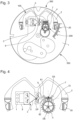
- the invention thus relates to a regulator mechanism 300 for a watch, comprising, arranged on a plate 1, a resonator mechanism 100 with a quality factor Q, and an escapement mechanism 200, which is subjected to a pair of motor means 400 which comprise a movement 500.
- This resonator mechanism 100 comprises an inertial element 2 which is arranged to oscillate relative to the plate 1.
- This inertial element 2 is subjected to the action of elastic return means 3 fixed directly or indirectly to the plate 1.
- the inertial element 2 is arranged to cooperate indirectly with an escapement wheel 4, in particular an escape wheel, which the escapement mechanism 200 comprises, and which pivots around an escapement axis DE.
- the resonator mechanism 100 is a rotary resonator with a virtual pivot, around a main axis DP, with flexible guidance comprising at least two flexible blades 5, and comprises a plate pin 6 secured to the inertial element 2.
- the escapement mechanism 200 comprises an anchor 7, which pivots around a secondary axis DS and comprises an anchor fork 8 arranged to cooperate with the plate pin 6, and is thus an escapement mechanism free: in its operating cycle, the resonator mechanism 100 has at least one phase of freedom where the plate pin 6 is at a distance from the anchor fork 8.
- the resonator lift angle ⁇ , during which the plate pin 6 is in contact with the anchor fork 8, is less than 10°.
- dynamic multi-body simulations i.e. relating to a set of several components each of which is assigned a particular mass and inertia distribution
- dynamic multi-body simulations make it possible to evaluate the efficiency and delay of this escapement mechanism as a function of the inertia ratio between the inertia of the inertial element and the inertia of the anchor, which standard kinematic simulations do not make it possible to establish.
- the analytical model of the system thus showed that, if we want to limit dynamic losses, a particular condition links the inertia of the anchor, the inertia of the inertial element, the quality factor of the resonator, and the lifting angles of the anchor and the inertial element: for a coefficient ⁇ of dynamic losses, the inertia I B of the inertial element 2 with respect to the main axis DP on the one hand, and the inertia I A of the anchor 7 with respect to the secondary axis DS on the other hand, are such that the ratio I B /I A is greater than 2Q. ⁇ 2 /( ⁇ . ⁇ . ⁇ 2 ), where ⁇ is the lifting angle of the anchor which corresponds to the maximum angular travel of the anchor fork 8.
- the inertia I B of the inertial element 2 with respect to the main axis DP on the one hand, and the inertia I A of the anchor 7 with respect to the secondary axis DS on the other hand are such that the ratio I B /I A is greater than 2Q. ⁇ 2 /(0.1. ⁇ . ⁇ 2 ), where ⁇ is the lifting angle of the anchor which corresponds to the maximum angular travel of the anchor fork 8.
- the resonator lift angle ⁇ which is an overall angle, taken on either side of the rest position, is less than twice the amplitude angle by which the inertial element 2 deviates at most from a rest position, in only one direction of its movement.
- the amplitude angle, from which the inertial element 2 deviates as much as possible from a rest position is between 5° and 40°.
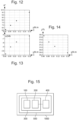
- the plate pin 6 penetrates into the anchor fork 8 with a penetration stroke P greater than 100 micrometers, and in a release phase the plate pin 6 remains at a distance from the anchor fork 8 with a safety distance S greater than 25 micrometers.
- Fork 8 of lever 7 is thus widened compared to what would be a classic Swiss lever fork, much narrower and allowing less freedom to ellipse 6, which would not be able to enter and exit the fork of a classic Swiss lever with such a small angular amplitude.
- This concept of widened fork makes it possible to operate a lever escapement even though the amplitude of the resonator is much lower than in a classic balance spring, which is particularly interesting for resonators with flexible guides, which have a low amplitude, as in this case. Indeed, it is important that, during the operating cycle, the balance is completely free at certain times.
- the plate pin 6 and the anchor fork 8 are advantageously dimensioned so that the width L of the anchor fork 8 is greater than (P+S)/sin( ⁇ /2+ ⁇ /2), the penetration stroke P and the safety distance S being measured radially relative to the main axis DP.
- the useful width L1 of the plate pin 6, visible on the figure 6 is slightly less than the width L of the anchor fork 8, and, more particularly, less than or equal to 98% of L.
- This plate pin 6 is advantageously tapered behind its surface of useful width L1, the pin may in particular have a prismatic shape of triangular section as suggested in the figure, or similar.
- the eccentricity E2 of the ellipse 6 relative to the balance axis, and the eccentricity E7 of the fork horn 8 relative to the balance axis anchor 7, are between 40% and 60% of the center distance E between the axis of anchor 7 and the axis of the balance. More particularly, the eccentricity E2 is between 55% and 60% of the center distance E, and the eccentricity E7 is between 40% and 45% of the center distance E. More particularly, the interference zone between ellipse 6 and fork 8 extends over 5% to 10% of the center distance E.
- the invention defines, by construction, a new pin-fork layout, which has a very particular characteristic, according to which the horns of the fork are further apart, and the pin is wider, than for a Swiss anchor mechanism of known type with a usual lifting angle of 50°.
- FIGS. 16 to 19 illustrate the kinematics and show that adequate penetrations P and safety devices S are available, with this combined design of the ellipse 6 very far from the balance axis, and of the anchor 7 of a particular shape and in particular with an enlarged fork.
- the anchor 7 is made of silicon, which allows a miniaturized and very precise execution, with a density less than a third of that of steel. Having a silicon anchor allows to reduce its inertia compared to a metal anchor. A low inertia of the anchor with respect to the balance is crucial to have a correct performance at low amplitude and high frequency, in this case resonators with flexible guides.
- the balance wheel is, when the watch range allows it, advantageously made of a heavy metal or alloy, including gold, platinum, tungsten, or similar, and may include weights of similar constitution. Failing this, the balance wheel is conventionally made of CuBe2 copper-beryllium alloy, or similar, and weighted with balancing weights and/or adjustment weights made of nickel silver or other alloy.
- this anchor 7 is on a single level of silicon, attached to a metal shaft, or similar, such as ceramic, or other, pivoted relative to the plate 1.
- escapement wheel 4 is a silicon escape wheel.
- the escapement wheel 4 is an escape wheel which is perforated to minimize its inertia relative to its pivot axis DE.
- the anchor 7 is perforated to minimize its inertia I A relative to the secondary axis DS.
- the anchor 7 is symmetrical with respect to the secondary axis DS, so as to avoid any imbalance, and to avoid parasitic torques during linear impacts, in particular in translation.
- An additional advantage is then the great ease of assembly of this very small component, which the operator carrying out the assembly can handle from any side.
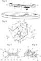
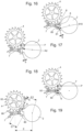
- FIG. 7 shows the two horns 81 and 82 arranged to cooperate with the chainring pin 6, the pallets 72 and 73 arranged to cooperate with teeth of the escapement wheel 4, and false horns 80 and false pallets 70 whose sole role is perfect balancing,
- the largest dimension of the inertial element 2 is larger than half of the largest dimension of the plate 1.
- the main axis DP, the secondary axis DS and the pivot axis of the escapement wheel 4 are arranged according to a right-angle pointing whose apex is on the secondary axis DS. It is understood that thus, with reference to a classic Swiss anchor in the shape of a T with a rod and two arms, the rod is removed, which becomes one of the two arms 76, visible on the figure 7 , which carries the horns 81 and 82 and the output pallet 72 almost merged with the horn 82, the other arm 75 carrying the input pallet 73.
- the comparison with the Swiss anchor is to be continued, as regards the means of preventing overturning, usually constituted by a dart located on a plane offset from the anchor.
- This function is important to avoid any jamming of the balance.
- the balance is devoid of small plate and therefore of a plate notch provided to cooperate with such a dart.
- the ellipse is never far from the fork.
- the anti-overturning function is then advantageously fulfilled by the combination of the circumference 60 in an arc of a circle of the ellipse 6, and by the corresponding surface 810, 820, of the anchor horn 81, 82 concerned: this horn plays the usual role of a dart, and the circumference of the ellipse plays the role of the small plate.
- the additional advantage which results from this is that, as regards its cooperation with the anchor of a single level, the balance can also be, locally, at a single level, which simplifies its manufacture and reduces its cost.
- the flexible guide comprises two flexible blades 5 crossed in projection on a plane perpendicular to the main axis DP, at the virtual pivot defining the main axis DP, and located in two parallel and distinct levels. More particularly still, the two flexible blades 5, in projection on a plane perpendicular to the main axis DP, form between them an angle of between 59.5° and 69.5°, and cross between 10.75% and 14.75% of their length, so as to provide the resonator mechanism 100 with a voluntary isochronism defect opposite to the escapement delay defect of the escapement mechanism 200.
- the resonator thus has an anisochronism curve which compensates for the delay caused by the escapement. That is to say that the free resonator is designed with an isochronism defect opposite to the defect caused by the lever escapement. The escapement delay is therefore compensated for by the design of the resonator.
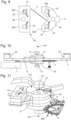
- each flexible blade 5 belongs to a single-piece assembly 50, in a single piece with two solid parts 51, 55, and with its first alignment means 52A, 52B, and fixing means 54 on the plate 1, or, advantageously and as visible on the figure 10 , for fixing on an intermediate elastic suspension blade 9 fixed to the plate 1 and which is arranged to allow movement of the flexible guide and the inertial element 2 according to the direction of the main axis DP, so as to ensure good protection against impacts of direction Z perpendicular to the plane of such a single-piece assembly 10, and therefore to avoid the breakage of the blades of the flexible guide.
- This intermediate elastic suspension blade 9 is advantageously made of “Durimphy” alloy or similar.
- the first alignment means are a first V 52A and a first flat 52B, and the first fixing means comprise at least a first bore 54.
- a first plating blade 53 provides support on the first fixing means.
- the single-piece assembly 50 comprises, for its fixing on the inertial element 2, second alignment means which are a second V 56A and a second flat 56B, and the second fixing means comprise at least a second bore 58.
- a second plating blade 57 provides support on the second fixing means.
- the flexible guide 3 with crossed blades 5 is advantageously made up of two identical 50-piece silicon monobloc assemblies, assembled symmetrically to form the crossing of the blades, and precisely aligned with each other thanks to the integrated alignment means and to auxiliary means such as pins and screws, not shown in the figures.
- At least the resonator mechanism 100 is fixed on an intermediate elastic suspension blade 9 fixed to the plate 1 and arranged to allow a movement of the resonator mechanism 100 in the direction of the main axis DP, and the plate 1 comprises at least one shock-absorbing stop 11, 12, at least in the direction of the main axis DP, and preferably at least two such shock-absorbing stops 11, 12, which are arranged to cooperate with at least one rigid element of the inertial element 2, for example a flange 21 or 22 added during the assembly of the inertial element with the flexible guide 3 comprising the blades 5.
- the elastic suspension blade 9, or a similar device allows movements of the entire resonator 100 substantially in the direction defined by the virtual axis of rotation DP of the guide.
- the purpose of this device is to prevent the blades 5 from breaking in the event of a transverse impact in the direction DP.
- the flange 21 or 22 comprises a bore 211 and a face 212, capable of cooperating respectively in shock-proof stop support with a journal 121 and a complementary surface 122 at the stop 21 or 22.
- the inertial element 2 comprises weights 20 for adjusting the speed and the imbalance.
- the tray pin 6 is a single piece with a flexible blade 5, or more particularly, such a single piece assembly 50 as illustrated in the figures.
- the anchor 7 comprises bearing surfaces arranged to cooperate in bearing with teeth that the escapement wheel 4 comprises and to limit the angular travel of the anchor 7. These supports make it possible to limit the angular travel of the anchor, as would do pins.
- the angular travel of the anchor 78 can also be conventionally limited by limiting pins 700.
- the flexible guide 3 is made of oxidized silicon to compensate for the effects of temperature on the operation of the regulating mechanism 300.
Landscapes
- Physics & Mathematics (AREA)
- General Physics & Mathematics (AREA)
- Micromachines (AREA)
- Piezo-Electric Or Mechanical Vibrators, Or Delay Or Filter Circuits (AREA)
- Electromechanical Clocks (AREA)
Claims (22)
- Regulator-Mechanismus (300) für die Uhrmacherei, der auf einer Platine (1) angeordnet einen Resonator-Mechanismus (100) mit einem Qualitätsfaktor Q und einen Hemmungsmechanismus (200) beinhaltet, der angeordnet ist, um einem Paar von Motormitteln (400) ausgesetzt zu sein, die ein Uhrwerk (500) beinhaltet, wobei der Resonator-Mechanismus (100) ein Trägheitselement (2) beinhaltet, das angeordnet ist, um in Bezug auf die Platine (1) zu schwingen, wobei das Trägheitselement (2) der Wirkung von elastischen Rückzugsmitteln (3) ausgesetzt ist, die direkt oder indirekt an der Platine (1) befestigt sind, wobei das Trägheitselement (2) angeordnet ist, um indirekt mit einem Hemmungsdrehteil (4) zusammenzuwirken, den der Hemmungsmechanismus (200) beinhaltet, wobei der Resonator-Mechanismus (100) ein um eine Hauptachse (DP) mit flexibler Führung drehender Resonator mit virtuellem Zapfen ist, der mindestens zwei flexible Klingen (5) beinhaltet, und einen Schalenstift (6) beinhaltet, der fest mit dem Trägheitselement (2) verbunden ist, und wobei der Hemmungsmechanismus (200) einen Anker (7) beinhaltet, der sich um eine Sekundärachse (DS) dreht, und eine Ankergabel (8) beinhaltet, die angeordnet ist, um mit dem Schalenstift (6) zusammenzuwirken, und ein freier Hemmungsmechanismus ist, in dessen Betriebszyklus der Resonator-Mechanismus (100) mindestens eine Freiheitsphase besitzt, in welcher der Schalenstift (6) im Abstand zur Ankergabel (8) ist, dadurch gekennzeichnet, dass die Hauptachse (DP), die Sekundärachse (DS) und die Drehachse (DE) des Hemmungsdrehteils (4) gemäß einer Peilung im rechten Winkel angeordnet sind, dessen Scheitelpunkt auf der Sekundärachse (DS) liegt, und dadurch, dass der gesamte Resonator-Hubwinkel (β), bei dem der Schalenstift (6) in Kontakt mit der Ankergabel (8) ist, kleiner als 10° ist.
- Regulator-Mechanismus (300) nach Anspruch 1, dadurch gekennzeichnet, dass die Trägheit IB des Trägheitselements (2) in Bezug auf die Hauptachse (DP) einerseits, und die Trägheit IA des Ankers (7) in Bezug auf die Sekundärachse (DS) andererseits so sind, dass das Verhältnis IB/IA größer als 2Q.a2/(π. β2/10) ist, wobei α der gesamte Anker-Hubwinkel ist, der dem maximalen Winkelweg der Ankergabel (8) entspricht, und β der gesamte Resonator-Hubwinkel ist.
- Regulator-Mechanismus (300) nach Anspruch 1 oder 2, dadurch gekennzeichnet, dass der gesamte Resonator-Hubwinkel (β) kleiner als das Doppelte des Amplitudenwinkels ist, von dem das Trägheitselement (2) in einer einzigen Richtung seiner Bewegung maximal von einer Ruheposition abweicht.
- Regulator-Mechanismus (300) nach einem der Ansprüche 1 bis 3, dadurch gekennzeichnet, dass der Amplitudenwinkel, um den das Trägheitselement (2) maximal von einer Ruheposition abweicht, zwischen 5° und 40° liegt.
- Regulator-Mechanismus (300) nach einem der Ansprüche 1 bis 4, dadurch gekennzeichnet, dass bei jedem Wechsel der Schalenstift (6) in einer Kontaktphase mit einem Eindringweg (P) von mehr als 100 Mikrometern in die Ankergabel (8) eindringt, und der Schalenstift (6) in einer Freigabephase mit einem Sicherheitsabstand (S) von mehr als 25 Mikrometern von der Ankergabel (8) beabstandet bleibt, und dadurch, dass der Schalenstift (6) und die Ankergabel (8) bemessen sind, damit die Breite (L) der Ankergabel (8) größer als (P+S)/sin(α/2+β/2) ist, wobei der Eindringweg (P) und der Sicherheitsabstand (S) radial in Bezug auf die Hauptachse (DP) gemessen werden.
- Regulator-Mechanismus (300) nach einem der Ansprüche 1 bis 5, dadurch gekennzeichnet, dass der Anker (7) aus einer einzigen Siliziumebene besteht, die auf einer Welle beigebracht ist, die in Bezug auf die Platine (1) gedreht wird.
- Regulator-Mechanismus (300) nach einem der Ansprüche 1 bis 6, dadurch gekennzeichnet, dass der Hemmungsdrehteil (4) ein Hemmungsrad aus Silizium ist.
- Regulator-Mechanismus (300) nach einem der Ansprüche 1 bis 7, dadurch gekennzeichnet, dass der Hemmungsdrehteil (4) ein Hemmungsrad ist, das durchbrochen ist, um seine Trägheit in Bezug auf seine Drehachse zu minimieren.
- Regulator-Mechanismus (300) nach einem der Ansprüche 1 bis 8, dadurch gekennzeichnet, dass der Anker (7) durchbrochen ist, um seine Trägheit (IA) in Bezug auf die Sekundärachse (DS) zu minimieren.
- Regulator-Mechanismus (300) nach einem der Ansprüche 1 bis 9, dadurch gekennzeichnet, dass der Anker (7) in Bezug auf die Sekundärachse (DS) symmetrisch ist.
- Regulator-Mechanismus (300) nach einem der Ansprüche 1 bis 10, dadurch gekennzeichnet, dass die größte Abmessung des Trägheitselements (2) größer als die Hälfte der größten Abmessung der Platine (1) ist.
- Regulator-Mechanismus (300) nach einem der Ansprüche 1 bis 11, dadurch gekennzeichnet, dass die flexible Führung zwei flexible Klingen (5) beinhaltet, die sich in der Projektion auf eine Ebene senkrecht zur Hauptachse (DP) im Bereich des virtuellen Zapfens, der die Hauptachse (DP) definiert, kreuzen, und sich in zwei parallelen und unterschiedlichen Ebenen befinden.
- Regulator-Mechanismus (300) nach Anspruch 12, dadurch gekennzeichnet, dass die beiden flexiblen Klingen (5) in der Projektion auf eine Ebene senkrecht zur Hauptachse (DP) zwischen sich einen Winkel zwischen 59,5° und 69,5° bilden und sich zwischen 10,75 % und 14,75 % ihrer Länge kreuzen, um dem Resonator-Mechanismus (100) einen absichtlichen Isochronismusfehler zu verschaffen, der dem Hemmungsnachlauffehler des Hemmungsmechanismus (200) entgegengesetzt ist.
- Regulator-Mechanismus (300) nach Anspruch 12 oder 13, dadurch gekennzeichnet, dass die beiden flexiblen Klingen (5) identisch sind und symmetrisch positioniert sind.
- Regulator-Mechanismus (300) nach einem der Ansprüche 12 bis 14, dadurch gekennzeichnet, dass jede der flexiblen Klingen (5) einer einteiligen Einheit (50) angehört, die aus einem Stück mit ihren Mitteln zur Ausrichtung und Befestigung an der genannten Platine (1) oder an einer elastischen Zwischenaufhängungsklinge (9) besteht, die an der Platine (1) befestigt und angeordnet ist, um eine Verschiebung der flexiblen Führung und des Trägheitselements (2) in Richtung der Hauptachse (DP) zuzulassen.
- Regulator-Mechanismus (300) nach einem der Ansprüche 1 bis 15, dadurch gekennzeichnet, dass mindestens der Resonator-Mechanismus (100) auf einer elastischen Zwischenaufhängungsklinge (9) befestigt ist, die an der Platine (1) befestigt ist und angeordnet ist, um eine Verschiebung des Resonator-Mechanismus (100) in Richtung der Hauptachse (DP) zuzulassen, und dadurch, dass die Platine (1) mindestens einen stosssicheren Anschlag (11, 12) mindestens in Richtung der Hauptachse (DP) beinhaltet, der angeordnet ist, um mit einem starren Element des Trägheitselements (2) zusammenzuwirken.
- Regulator-Mechanismus (300) nach einem der Ansprüche 1 bis 16, dadurch gekennzeichnet, dass das Trägheitselement (2) Gewichtchen zur Einstellung des Gangs und der Unwucht beinhaltet.
- Regulator-Mechanismus (300) nach einem der Ansprüche 1 bis 17, dadurch gekennzeichnet, dass der Schalenstift (6) in einem Stück mit einer flexiblen Klinge (5) ist.
- Regulator-Mechanismus (300) nach einem der Ansprüche 1 bis 18, dadurch gekennzeichnet, dass der Anker (7) Auflageflächen beinhaltet, die angeordnet sind, um in Auflage mit Zähnen zusammenzuwirken, die der Hemmungsdrehteil (4) beinhaltet, und um den Winkelweg des Ankers (7) zu begrenzen.
- Regulator-Mechanismus (300) nach einem der Ansprüche 1 bis 19, dadurch gekennzeichnet, dass die flexible Führung aus oxidiertem Silizium besteht, um die Auswirkungen der Temperatur auf den Gang des Regulator-Mechanismus (300) zu kompensieren.
- Uhrwerk (500), das Motormittel (400) und einen Regulator-Mechanismus (300) nach einem der Ansprüche 1 bis 20 beinhaltet, dessen Hemmungsmechanismus (200) dem Moment der Motormittel (400) ausgesetzt ist.
- Uhr (1000), die ein Uhrwerk (500) nach Anspruch 21, und/oder einen Regulator-Mechanismus (300) nach einem der Ansprüche 1 bis 20 beinhaltet.
Applications Claiming Priority (2)
| Application Number | Priority Date | Filing Date | Title |
|---|---|---|---|
| EP16200152.3A EP3327515B1 (de) | 2016-11-23 | 2016-11-23 | Sich drehender resonator mit einer flexiblen führung, der von einer freien ankerhemmung gehalten wird |
| PCT/EP2017/069043 WO2018095596A2 (fr) | 2016-11-23 | 2017-07-27 | Résonateur rotatif à guidage flexible entretenu par un échappement libre à ancre |
Publications (2)
| Publication Number | Publication Date |
|---|---|
| EP3545367A2 EP3545367A2 (de) | 2019-10-02 |
| EP3545367B1 true EP3545367B1 (de) | 2025-01-15 |
Family
ID=57391852
Family Applications (9)
| Application Number | Title | Priority Date | Filing Date |
|---|---|---|---|
| EP16200152.3A Active EP3327515B1 (de) | 2016-11-23 | 2016-11-23 | Sich drehender resonator mit einer flexiblen führung, der von einer freien ankerhemmung gehalten wird |
| EP17745180.4A Active EP3545365B1 (de) | 2016-11-23 | 2017-07-27 | Sich drehender resonator mit einer flexiblen führung, der von einer freien ankerhemmung gehalten wird |
| EP17749674.2A Active EP3545367B1 (de) | 2016-11-23 | 2017-07-27 | Sich drehender resonator mit einer flexiblen führung, der von einer freien ankerhemmung gehalten wird |
| EP17745179.6A Active EP3545364B1 (de) | 2016-11-23 | 2017-07-27 | Sich drehender resonator mit einer flexiblen führung, der von einer freien ankerhemmung gehalten wird |
| EP17745178.8A Active EP3545363B1 (de) | 2016-11-23 | 2017-07-27 | Sich drehender resonator mit einer flexiblen führung, der von einer freien ankerhemmung gehalten wird |
| EP17746073.0A Active EP3545366B1 (de) | 2016-11-23 | 2017-07-27 | Sich drehender resonator mit einer flexiblen führung, der von einer freien ankerhemmung gehalten wird |
| EP17752312.3A Active EP3545368B1 (de) | 2016-11-23 | 2017-07-27 | Sich drehender resonator mit einer flexiblen führung, der von einer freien ankerhemmung gehalten wird |
| EP17794727.2A Active EP3545369B1 (de) | 2016-11-23 | 2017-11-07 | Sich drehender resonator mit einer flexiblen führung, der von einer freien ankerhemmung gehalten wird |
| EP17803933.5A Active EP3545370B1 (de) | 2016-11-23 | 2017-11-22 | Rotierender resonator mit flexiblem führungssystem auf basis einer abgelösten ankerhemmung |
Family Applications Before (2)
| Application Number | Title | Priority Date | Filing Date |
|---|---|---|---|
| EP16200152.3A Active EP3327515B1 (de) | 2016-11-23 | 2016-11-23 | Sich drehender resonator mit einer flexiblen führung, der von einer freien ankerhemmung gehalten wird |
| EP17745180.4A Active EP3545365B1 (de) | 2016-11-23 | 2017-07-27 | Sich drehender resonator mit einer flexiblen führung, der von einer freien ankerhemmung gehalten wird |
Family Applications After (6)
| Application Number | Title | Priority Date | Filing Date |
|---|---|---|---|
| EP17745179.6A Active EP3545364B1 (de) | 2016-11-23 | 2017-07-27 | Sich drehender resonator mit einer flexiblen führung, der von einer freien ankerhemmung gehalten wird |
| EP17745178.8A Active EP3545363B1 (de) | 2016-11-23 | 2017-07-27 | Sich drehender resonator mit einer flexiblen führung, der von einer freien ankerhemmung gehalten wird |
| EP17746073.0A Active EP3545366B1 (de) | 2016-11-23 | 2017-07-27 | Sich drehender resonator mit einer flexiblen führung, der von einer freien ankerhemmung gehalten wird |
| EP17752312.3A Active EP3545368B1 (de) | 2016-11-23 | 2017-07-27 | Sich drehender resonator mit einer flexiblen führung, der von einer freien ankerhemmung gehalten wird |
| EP17794727.2A Active EP3545369B1 (de) | 2016-11-23 | 2017-11-07 | Sich drehender resonator mit einer flexiblen führung, der von einer freien ankerhemmung gehalten wird |
| EP17803933.5A Active EP3545370B1 (de) | 2016-11-23 | 2017-11-22 | Rotierender resonator mit flexiblem führungssystem auf basis einer abgelösten ankerhemmung |
Country Status (6)
| Country | Link |
|---|---|
| US (6) | US11520289B2 (de) |
| EP (9) | EP3327515B1 (de) |
| JP (6) | JP6931392B2 (de) |
| CN (6) | CN110023846B (de) |
| CH (1) | CH713150A2 (de) |
| WO (8) | WO2018095593A2 (de) |
Families Citing this family (20)
| Publication number | Priority date | Publication date | Assignee | Title |
|---|---|---|---|---|
| CH713151B1 (fr) * | 2016-11-23 | 2020-09-30 | Swatch Group Res & Dev Ltd | Lame flexible pour l'horlogerie, et procédé de fabrication. |
| EP3327515B1 (de) | 2016-11-23 | 2020-05-06 | ETA SA Manufacture Horlogère Suisse | Sich drehender resonator mit einer flexiblen führung, der von einer freien ankerhemmung gehalten wird |
| EP3425458A1 (de) * | 2017-07-07 | 2019-01-09 | ETA SA Manufacture Horlogère Suisse | Abtrennbares stück eines uhrenoszillators |
| EP3438762A3 (de) * | 2017-07-28 | 2019-03-13 | The Swatch Group Research and Development Ltd | Uhrwerkoszillator mit flexiblen führungen mit grosser winkelförmiger laufbahn |
| EP3561607B1 (de) | 2018-04-23 | 2022-03-16 | ETA SA Manufacture Horlogère Suisse | Stossdämpfungsschutz eines resonatormechanismus mit flexibler drehführung |
| EP3561609B1 (de) * | 2018-04-23 | 2022-03-23 | ETA SA Manufacture Horlogère Suisse | Stossdämpfungsschutz eines resonatormechanismus mit flexibler drehführung |
| JP6843191B2 (ja) * | 2018-07-24 | 2021-03-17 | ザ・スウォッチ・グループ・リサーチ・アンド・ディベロップメント・リミテッド | 長い角ストロークを有するフレクシャーベアリングを備えた計時器用発振器 |
| US11454932B2 (en) * | 2018-07-24 | 2022-09-27 | The Swatch Group Research And Development Ltd | Method for making a flexure bearing mechanism for a mechanical timepiece oscillator |
| EP3627237B1 (de) * | 2018-09-20 | 2022-04-06 | ETA SA Manufacture Horlogère Suisse | Komponente aus mikrobearbeitbarem material für resonator mit hohem qualitätsfaktor |
| JP7485506B2 (ja) * | 2018-10-12 | 2024-05-16 | ロレックス・ソシエテ・アノニム | 小型時計ムーブメント用の調速装置 |
| US12287609B2 (en) | 2019-07-12 | 2025-04-29 | Patek Philippe Sa Geneve | Method for adjustment of a flexute pivot timepiece oscillator |
| EP3783445B1 (de) * | 2019-08-22 | 2023-06-14 | ETA SA Manufacture Horlogère Suisse | Einstellmechanismus einer uhr mit hohem qualitätsfaktor und minimaler schmierung |
| EP3812842B1 (de) * | 2019-10-24 | 2023-11-29 | The Swatch Group Research and Development Ltd | Schwenkbare führungsvorrichtung für eine schwenkbare masse, und resonatormechanismus einer uhr |
| EP3812843B1 (de) * | 2019-10-25 | 2025-04-23 | ETA SA Manufacture Horlogère Suisse | Flexible führung und gesamtheit von übereinander angeordneten flexiblen führungen für sich drehenden resonatormechanismus, insbesondere für uhrwerk |
| EP3926412A1 (de) * | 2020-06-16 | 2021-12-22 | Montres Breguet S.A. | Regulator eines uhrwerks |
| EP3971655A1 (de) * | 2020-09-18 | 2022-03-23 | ETA SA Manufacture Horlogère Suisse | Stossdämpfungsschutz mit anschlag eines resonatormechanismus mit flexibler drehführung |
| EP3982204A1 (de) * | 2020-10-08 | 2022-04-13 | The Swatch Group Research and Development Ltd | Uhrresonator, der mindestens eine flexible führung umfasst |
| EP4134754A1 (de) | 2021-08-13 | 2023-02-15 | ETA SA Manufacture Horlogère Suisse | Trägheitsmasse, die mit einem flexiblen trägheitselement ausgestattet ist, insbesondere für uhrwerke |
| EP4160323A1 (de) * | 2021-10-04 | 2023-04-05 | CSEM Centre Suisse d'Electronique et de Microtechnique SA - Recherche et Développement | Mechanische einstellvorrichtung für uhr mit selbstanlaufendem, halb freistehendem hemmungsmechanismus mit geringem anstellwinkel |
| EP4187326A1 (de) * | 2021-11-29 | 2023-05-31 | Omega SA | Spiralfeder für resonatormechanismus eines uhrwerks, der mit mitteln zum ausgleichen der starrheit ausgestattet ist |
Family Cites Families (43)
| Publication number | Priority date | Publication date | Assignee | Title |
|---|---|---|---|---|
| US2663139A (en) * | 1949-10-31 | 1953-12-22 | Gibbs Mfg And Res Corp | Pallet lever construction |
| NL94759C (de) * | 1952-07-14 | |||
| CH469299A (fr) * | 1967-03-31 | 1969-04-15 | Centre Electron Horloger | Résonateur mécanique pour pièce d'horlogerie |
| GB1195432A (en) * | 1967-05-15 | 1970-06-17 | Horstmann Magnetics Ltd | Electromechanical Oscillators |
| CH1089267A4 (de) * | 1967-08-02 | 1970-01-30 | ||
| US3834155A (en) * | 1974-02-19 | 1974-09-10 | Timex Corp | Offset pallet lever for watch escapement |
| CH599585B5 (de) * | 1975-08-05 | 1978-05-31 | Ebauchesfabrik Eta Ag | |
| JPH02273323A (ja) | 1989-04-14 | 1990-11-07 | Fuji Electric Co Ltd | 強磁性体のスパツタリング装置 |
| CH698105B1 (fr) * | 2004-10-20 | 2009-05-29 | Vaucher Mft Fleurier Sa | Dispositif de remontoir et de mise à l'heure. |
| DE602007001230D1 (de) * | 2007-03-09 | 2009-07-16 | Eta Sa Mft Horlogere Suisse | Hemmung mit Tangentialimpulsen |
| CH705276B1 (fr) * | 2007-12-28 | 2013-01-31 | Chopard Technologies Sa | Organe d'entraînement et de transmission pour un échappement à ancre, plateau et échappement en étant équipés, et pièce d'horlogerie les comportant. |
| EP2230572B1 (de) | 2009-03-17 | 2012-01-25 | Nivarox-FAR S.A. | Radialverschlusssystem für Uhrwerkskomponente |
| CH700640B1 (fr) * | 2009-03-19 | 2014-09-30 | Mhvj Manufacture Horlogère Vallée De Joux | Pièce d'horlogerie allegée et renforcée. |
| CH701421B1 (fr) * | 2009-07-10 | 2014-11-28 | Manuf Et Fabrique De Montres Et Chronomètres Ulysse Nardin Le Locle Sa | Oscillateur mécanique. |
| EP2363762B1 (de) * | 2010-03-04 | 2017-11-22 | Montres Breguet SA | Uhr mit einem mechanischen Hochfrequenzuhrwerk |
| EP2407830B1 (de) * | 2010-07-15 | 2014-11-05 | Rolex Sa | Uhr |
| CH703464B1 (fr) * | 2010-07-19 | 2013-11-29 | Nivarox Sa | Mécanisme oscillant à pivot élastique. |
| CN103097965B (zh) * | 2010-07-19 | 2015-05-13 | 尼瓦洛克斯-法尔股份有限公司 | 具有弹性枢轴的振荡机构和用于传递能量的可动元件 |
| EP2413202B1 (de) * | 2010-07-30 | 2017-11-15 | ETA SA Manufacture Horlogère Suisse | Verfahren zur Verbesserung der Verschleiss- und Stossfestigkeit einer Uhrwerkskomponente. Verschleiß- und stoßfester Anker für Uhrwerk |
| KR101208560B1 (ko) | 2010-09-03 | 2012-12-05 | 엘지전자 주식회사 | 무선 접속 시스템에서 할당 세컨더리 캐리어의 스캐닝 수행 방법 및 장치 |
| EP2652559B1 (de) * | 2010-12-14 | 2019-04-24 | Chopard Technologies SA | Hebel und auslösemechanismus mit einem solchen hebel |
| EP2557460A1 (de) * | 2011-08-12 | 2013-02-13 | Nivarox-FAR S.A. | Metallanker mit Polymer-Hörnern |
| EP2574994A1 (de) * | 2011-09-29 | 2013-04-03 | Asgalium Unitec SA | Stimmgabelresonator für ein mechanisches Uhrwerk |
| JP5918438B2 (ja) * | 2012-03-29 | 2016-05-18 | ニヴァロックス−ファー ソシエテ アノニム | 可動フレームを備えた可撓性エスケープ機構 |
| EP2706416B1 (de) * | 2012-09-07 | 2015-11-18 | The Swatch Group Research and Development Ltd | Flexibler Anker mit konstanter Kraft |
| CH706924A2 (fr) * | 2012-09-07 | 2014-03-14 | Nivarox Sa | Ancre flexible à force constante et échappement muni d'une telle ancre. |
| JP6355102B2 (ja) * | 2013-09-04 | 2018-07-11 | セイコーインスツル株式会社 | 定力装置、ムーブメントおよび機械式時計 |
| EP2863273B1 (de) * | 2013-10-16 | 2016-01-13 | Montres Breguet SA | Hemmungsmechanismus für Uhrwerk einer Armbanduhr |
| EP3299907A1 (de) * | 2013-12-23 | 2018-03-28 | ETA SA Manufacture Horlogère Suisse | Mechanisches uhrwerk mit magnetischem hemmungsmechanismus |
| EP2911012B1 (de) * | 2014-02-20 | 2020-07-22 | CSEM Centre Suisse d'Electronique et de Microtechnique SA - Recherche et Développement | Oszillator einer Uhr |
| EP2977830B1 (de) * | 2014-07-23 | 2017-08-30 | Nivarox-FAR S.A. | Uhrhemmungsmechanismus mit konstanter Kraft |
| EP3191896B1 (de) * | 2014-09-09 | 2019-04-24 | The Swatch Group Research and Development Ltd | Kombinierter resonator mit verbessertem isochronismus |
| EP3021174A1 (de) * | 2014-11-17 | 2016-05-18 | LVMH Swiss Manufactures SA | Monolithischer Uhrregler, Uhrwerk und Uhr mit einem solchem Uhrregler |
| EP3032352A1 (de) | 2014-12-09 | 2016-06-15 | LVMH Swiss Manufactures SA | Uhrregler, Uhrwerk und Uhr mit solch einem Regler |
| CH710537A2 (fr) * | 2014-12-18 | 2016-06-30 | Swatch Group Res & Dev Ltd | Oscillateur d'horlogerie à diapason. |
| CH710524A2 (fr) * | 2014-12-18 | 2016-06-30 | Swatch Group Res & Dev Ltd | Résonateur d'horlogerie à lames croisées. |
| EP3254158B1 (de) * | 2015-02-03 | 2023-07-05 | ETA SA Manufacture Horlogère Suisse | Isochroner resonator für uhr |
| CH710759A2 (fr) * | 2015-02-20 | 2016-08-31 | Nivarox Far Sa | Oscillateur pour une pièce d'horlogerie. |
| AU2016372408B2 (en) * | 2015-12-14 | 2021-05-13 | MAX-PLANCK-Gesellschaft zur Förderung der Wissenschaften e.V. | Water-soluble derivatives of 3,5-diphenyl-diazole compounds |
| PL230779B1 (pl) * | 2016-06-03 | 2018-12-31 | Int Tobacco Machinery Poland Spolka Z Ograniczona Odpowiedzialnoscia | Urządzenie do identyfikacji parametrów fizycznych artykułów prętopodobnych przemysłu tytoniowego |
| WO2018017145A1 (en) * | 2016-07-22 | 2018-01-25 | Westinghouse Electric Company Llc | Spray methods for coating nuclear fuel rods to add corrosion resistant barrier |
| MX2019000984A (es) * | 2016-08-15 | 2019-07-04 | Givaudan Sa | Proceso para preparacion de indanonas. |
| EP3327515B1 (de) | 2016-11-23 | 2020-05-06 | ETA SA Manufacture Horlogère Suisse | Sich drehender resonator mit einer flexiblen führung, der von einer freien ankerhemmung gehalten wird |
-
2016
- 2016-11-23 EP EP16200152.3A patent/EP3327515B1/de active Active
- 2016-11-23 CH CH01544/16A patent/CH713150A2/fr unknown
-
2017
- 2017-07-27 CN CN201780072327.1A patent/CN110023846B/zh active Active
- 2017-07-27 WO PCT/EP2017/069038 patent/WO2018095593A2/fr not_active Ceased
- 2017-07-27 EP EP17745180.4A patent/EP3545365B1/de active Active
- 2017-07-27 EP EP17749674.2A patent/EP3545367B1/de active Active
- 2017-07-27 CN CN201780072284.7A patent/CN109983410B/zh active Active
- 2017-07-27 JP JP2019526552A patent/JP6931392B2/ja active Active
- 2017-07-27 EP EP17745179.6A patent/EP3545364B1/de active Active
- 2017-07-27 US US16/347,286 patent/US11520289B2/en active Active
- 2017-07-27 US US16/462,801 patent/US11487245B2/en active Active
- 2017-07-27 WO PCT/EP2017/069037 patent/WO2018095592A1/fr not_active Ceased
- 2017-07-27 JP JP2019527346A patent/JP6931395B2/ja active Active
- 2017-07-27 WO PCT/EP2017/069039 patent/WO2018099616A2/fr not_active Ceased
- 2017-07-27 US US16/344,567 patent/US11619909B2/en active Active
- 2017-07-27 EP EP17745178.8A patent/EP3545363B1/de active Active
- 2017-07-27 JP JP2019527338A patent/JP6931394B2/ja active Active
- 2017-07-27 EP EP17746073.0A patent/EP3545366B1/de active Active
- 2017-07-27 WO PCT/EP2017/069041 patent/WO2018095595A1/fr not_active Ceased
- 2017-07-27 JP JP2019547760A patent/JP6828179B2/ja active Active
- 2017-07-27 WO PCT/EP2017/069040 patent/WO2018095594A1/fr not_active Ceased
- 2017-07-27 CN CN201780072276.2A patent/CN109983409B/zh active Active
- 2017-07-27 CN CN201780072304.0A patent/CN110023845B/zh active Active
- 2017-07-27 WO PCT/EP2017/069043 patent/WO2018095596A2/fr not_active Ceased
- 2017-07-27 EP EP17752312.3A patent/EP3545368B1/de active Active
- 2017-11-07 US US16/462,812 patent/US11467537B2/en active Active
- 2017-11-07 CN CN201780072329.0A patent/CN110023847B/zh active Active
- 2017-11-07 EP EP17794727.2A patent/EP3545369B1/de active Active
- 2017-11-07 WO PCT/EP2017/078497 patent/WO2018103978A2/fr not_active Ceased
- 2017-11-07 JP JP2019547766A patent/JP6828180B2/ja active Active
- 2017-11-22 CN CN201780072330.3A patent/CN110235064B/zh active Active
- 2017-11-22 US US16/343,509 patent/US11493882B2/en active Active
- 2017-11-22 WO PCT/EP2017/080121 patent/WO2018095997A2/fr not_active Ceased
- 2017-11-22 JP JP2019524176A patent/JP6810800B2/ja active Active
- 2017-11-22 EP EP17803933.5A patent/EP3545370B1/de active Active
-
2019
- 2019-05-21 US US16/418,697 patent/US11675312B2/en active Active
Also Published As
Similar Documents
| Publication | Publication Date | Title |
|---|---|---|
| EP3545367B1 (de) | Sich drehender resonator mit einer flexiblen führung, der von einer freien ankerhemmung gehalten wird | |
| EP3382472A1 (de) | Führungslager einer unruhwelle einer uhr | |
| EP2781965B1 (de) | Kassette für Uhrwerksmechanismus | |
| EP3435173A1 (de) | Mechanisches uhrwerk mit sich drehendem isochronem resonator, der positionsunempfindlich ist | |
| EP2466397B1 (de) | Drehteil einer Uhr mit peripherem Antrieb | |
| CH714361A2 (fr) | Résonateur rotatif à guidage flexible entretenu par un échappement libre à ancre. | |
| EP3185083A1 (de) | Mechanischer uhrmechanismus mit einer ankerhemmung | |
| EP3971655A1 (de) | Stossdämpfungsschutz mit anschlag eines resonatormechanismus mit flexibler drehführung | |
| EP3451073B1 (de) | Uhrwerkoszillator mit flexiblen führungen mit grosser winkelförmiger laufbahn | |
| EP3761122B1 (de) | Drehteil für uhrhemmung, entsprechender hemmungsmechanismus und entsprechendes uhrenteil | |
| CH717880A2 (fr) | Mécanisme résonateur à guidage flexible rotatif avec protection antichoc à butée. | |
| EP3663868A1 (de) | Uhrwerk, das ein tourbillon mit einem festen magnetischen rad umfasst | |
| CH717575A2 (fr) | Mouvement d'horlogerie comportant un résonateur à masse inertielle à guidage flexible et un mécanisme d'échappement. | |
| CH717573A2 (fr) | Mouvement d'horlogerie comportant un résonateur à masse inertielle à guidage flexible et un mécanisme d'échappement. | |
| CH717580A2 (fr) | Mouvement d'horlogerie comportant un résonateur à masse inertielle et un mécanisme d'échappement. | |
| CH717578A2 (fr) | Mouvement d'horlogerie comportant un résonateur à masse inertielle et un mécanisme d'échappement. | |
| CH704239A2 (fr) | Mobile d'horlogerie à guidage périphérique. |
Legal Events
| Date | Code | Title | Description |
|---|---|---|---|
| STAA | Information on the status of an ep patent application or granted ep patent |
Free format text: STATUS: UNKNOWN |
|
| STAA | Information on the status of an ep patent application or granted ep patent |
Free format text: STATUS: THE INTERNATIONAL PUBLICATION HAS BEEN MADE |
|
| PUAI | Public reference made under article 153(3) epc to a published international application that has entered the european phase |
Free format text: ORIGINAL CODE: 0009012 |
|
| STAA | Information on the status of an ep patent application or granted ep patent |
Free format text: STATUS: REQUEST FOR EXAMINATION WAS MADE |
|
| 17P | Request for examination filed |
Effective date: 20190624 |
|
| AK | Designated contracting states |
Kind code of ref document: A2 Designated state(s): AL AT BE BG CH CY CZ DE DK EE ES FI FR GB GR HR HU IE IS IT LI LT LU LV MC MK MT NL NO PL PT RO RS SE SI SK SM TR |
|
| AX | Request for extension of the european patent |
Extension state: BA ME |
|
| DAV | Request for validation of the european patent (deleted) | ||
| DAX | Request for extension of the european patent (deleted) | ||
| STAA | Information on the status of an ep patent application or granted ep patent |
Free format text: STATUS: EXAMINATION IS IN PROGRESS |
|
| 17Q | First examination report despatched |
Effective date: 20211011 |
|
| 17Q | First examination report despatched |
Effective date: 20211022 |
|
| P01 | Opt-out of the competence of the unified patent court (upc) registered |
Effective date: 20230701 |
|
| GRAP | Despatch of communication of intention to grant a patent |
Free format text: ORIGINAL CODE: EPIDOSNIGR1 |
|
| STAA | Information on the status of an ep patent application or granted ep patent |
Free format text: STATUS: GRANT OF PATENT IS INTENDED |
|
| RIC1 | Information provided on ipc code assigned before grant |
Ipc: G04B 17/28 20060101ALI20240920BHEP Ipc: G04B 18/02 20060101ALI20240920BHEP Ipc: G04B 31/00 20060101ALI20240920BHEP Ipc: G04B 15/14 20060101ALI20240920BHEP Ipc: G04B 17/04 20060101ALI20240920BHEP Ipc: G04B 17/26 20060101ALI20240920BHEP Ipc: G04B 15/08 20060101AFI20240920BHEP |
|
| INTG | Intention to grant announced |
Effective date: 20241010 |
|
| GRAS | Grant fee paid |
Free format text: ORIGINAL CODE: EPIDOSNIGR3 |
|
| GRAA | (expected) grant |
Free format text: ORIGINAL CODE: 0009210 |
|
| STAA | Information on the status of an ep patent application or granted ep patent |
Free format text: STATUS: THE PATENT HAS BEEN GRANTED |
|
| AK | Designated contracting states |
Kind code of ref document: B1 Designated state(s): AL AT BE BG CH CY CZ DE DK EE ES FI FR GB GR HR HU IE IS IT LI LT LU LV MC MK MT NL NO PL PT RO RS SE SI SK SM TR |
|
| REG | Reference to a national code |
Ref country code: CH Ref legal event code: EP Ref country code: GB Ref legal event code: FG4D Free format text: NOT ENGLISH |
|
| REG | Reference to a national code |
Ref country code: DE Ref legal event code: R096 Ref document number: 602017087346 Country of ref document: DE |
|
| REG | Reference to a national code |
Ref country code: IE Ref legal event code: FG4D Free format text: LANGUAGE OF EP DOCUMENT: FRENCH |
|
| REG | Reference to a national code |
Ref country code: NL Ref legal event code: MP Effective date: 20250115 |
|
| PG25 | Lapsed in a contracting state [announced via postgrant information from national office to epo] |
Ref country code: NL Free format text: LAPSE BECAUSE OF FAILURE TO SUBMIT A TRANSLATION OF THE DESCRIPTION OR TO PAY THE FEE WITHIN THE PRESCRIBED TIME-LIMIT Effective date: 20250115 |
|
| PG25 | Lapsed in a contracting state [announced via postgrant information from national office to epo] |
Ref country code: RS Free format text: LAPSE BECAUSE OF FAILURE TO SUBMIT A TRANSLATION OF THE DESCRIPTION OR TO PAY THE FEE WITHIN THE PRESCRIBED TIME-LIMIT Effective date: 20250415 |
|
| PG25 | Lapsed in a contracting state [announced via postgrant information from national office to epo] |
Ref country code: FI Free format text: LAPSE BECAUSE OF FAILURE TO SUBMIT A TRANSLATION OF THE DESCRIPTION OR TO PAY THE FEE WITHIN THE PRESCRIBED TIME-LIMIT Effective date: 20250115 |
|
| PG25 | Lapsed in a contracting state [announced via postgrant information from national office to epo] |
Ref country code: PL Free format text: LAPSE BECAUSE OF FAILURE TO SUBMIT A TRANSLATION OF THE DESCRIPTION OR TO PAY THE FEE WITHIN THE PRESCRIBED TIME-LIMIT Effective date: 20250115 |
|
| PG25 | Lapsed in a contracting state [announced via postgrant information from national office to epo] |
Ref country code: ES Free format text: LAPSE BECAUSE OF FAILURE TO SUBMIT A TRANSLATION OF THE DESCRIPTION OR TO PAY THE FEE WITHIN THE PRESCRIBED TIME-LIMIT Effective date: 20250115 |
|
| PGFP | Annual fee paid to national office [announced via postgrant information from national office to epo] |
Ref country code: GB Payment date: 20250619 Year of fee payment: 9 |
|
| REG | Reference to a national code |
Ref country code: LT Ref legal event code: MG9D |
|
| PG25 | Lapsed in a contracting state [announced via postgrant information from national office to epo] |
Ref country code: NO Free format text: LAPSE BECAUSE OF FAILURE TO SUBMIT A TRANSLATION OF THE DESCRIPTION OR TO PAY THE FEE WITHIN THE PRESCRIBED TIME-LIMIT Effective date: 20250415 Ref country code: IS Free format text: LAPSE BECAUSE OF FAILURE TO SUBMIT A TRANSLATION OF THE DESCRIPTION OR TO PAY THE FEE WITHIN THE PRESCRIBED TIME-LIMIT Effective date: 20250515 |
|
| REG | Reference to a national code |
Ref country code: AT Ref legal event code: MK05 Ref document number: 1760231 Country of ref document: AT Kind code of ref document: T Effective date: 20250115 |
|
| PG25 | Lapsed in a contracting state [announced via postgrant information from national office to epo] |
Ref country code: HR Free format text: LAPSE BECAUSE OF FAILURE TO SUBMIT A TRANSLATION OF THE DESCRIPTION OR TO PAY THE FEE WITHIN THE PRESCRIBED TIME-LIMIT Effective date: 20250115 |
|
| PG25 | Lapsed in a contracting state [announced via postgrant information from national office to epo] |
Ref country code: LV Free format text: LAPSE BECAUSE OF FAILURE TO SUBMIT A TRANSLATION OF THE DESCRIPTION OR TO PAY THE FEE WITHIN THE PRESCRIBED TIME-LIMIT Effective date: 20250115 Ref country code: PT Free format text: LAPSE BECAUSE OF FAILURE TO SUBMIT A TRANSLATION OF THE DESCRIPTION OR TO PAY THE FEE WITHIN THE PRESCRIBED TIME-LIMIT Effective date: 20250515 |
|
| PGFP | Annual fee paid to national office [announced via postgrant information from national office to epo] |
Ref country code: FR Payment date: 20250620 Year of fee payment: 9 |
|
| PG25 | Lapsed in a contracting state [announced via postgrant information from national office to epo] |
Ref country code: BG Free format text: LAPSE BECAUSE OF FAILURE TO SUBMIT A TRANSLATION OF THE DESCRIPTION OR TO PAY THE FEE WITHIN THE PRESCRIBED TIME-LIMIT Effective date: 20250115 Ref country code: GR Free format text: LAPSE BECAUSE OF FAILURE TO SUBMIT A TRANSLATION OF THE DESCRIPTION OR TO PAY THE FEE WITHIN THE PRESCRIBED TIME-LIMIT Effective date: 20250416 |
|
| PG25 | Lapsed in a contracting state [announced via postgrant information from national office to epo] |
Ref country code: AT Free format text: LAPSE BECAUSE OF FAILURE TO SUBMIT A TRANSLATION OF THE DESCRIPTION OR TO PAY THE FEE WITHIN THE PRESCRIBED TIME-LIMIT Effective date: 20250115 |
|
| PG25 | Lapsed in a contracting state [announced via postgrant information from national office to epo] |
Ref country code: SE Free format text: LAPSE BECAUSE OF FAILURE TO SUBMIT A TRANSLATION OF THE DESCRIPTION OR TO PAY THE FEE WITHIN THE PRESCRIBED TIME-LIMIT Effective date: 20250115 |
|
| PG25 | Lapsed in a contracting state [announced via postgrant information from national office to epo] |
Ref country code: SM Free format text: LAPSE BECAUSE OF FAILURE TO SUBMIT A TRANSLATION OF THE DESCRIPTION OR TO PAY THE FEE WITHIN THE PRESCRIBED TIME-LIMIT Effective date: 20250115 |
|
| PG25 | Lapsed in a contracting state [announced via postgrant information from national office to epo] |
Ref country code: DK Free format text: LAPSE BECAUSE OF FAILURE TO SUBMIT A TRANSLATION OF THE DESCRIPTION OR TO PAY THE FEE WITHIN THE PRESCRIBED TIME-LIMIT Effective date: 20250115 |
|
| PGFP | Annual fee paid to national office [announced via postgrant information from national office to epo] |
Ref country code: DE Payment date: 20250620 Year of fee payment: 9 |
|
| PG25 | Lapsed in a contracting state [announced via postgrant information from national office to epo] |
Ref country code: IT Free format text: LAPSE BECAUSE OF FAILURE TO SUBMIT A TRANSLATION OF THE DESCRIPTION OR TO PAY THE FEE WITHIN THE PRESCRIBED TIME-LIMIT Effective date: 20250115 |
|
| REG | Reference to a national code |
Ref country code: DE Ref legal event code: R097 Ref document number: 602017087346 Country of ref document: DE |
|
| PGFP | Annual fee paid to national office [announced via postgrant information from national office to epo] |
Ref country code: CH Payment date: 20250801 Year of fee payment: 9 |
|
| PG25 | Lapsed in a contracting state [announced via postgrant information from national office to epo] |
Ref country code: EE Free format text: LAPSE BECAUSE OF FAILURE TO SUBMIT A TRANSLATION OF THE DESCRIPTION OR TO PAY THE FEE WITHIN THE PRESCRIBED TIME-LIMIT Effective date: 20250115 Ref country code: CZ Free format text: LAPSE BECAUSE OF FAILURE TO SUBMIT A TRANSLATION OF THE DESCRIPTION OR TO PAY THE FEE WITHIN THE PRESCRIBED TIME-LIMIT Effective date: 20250115 |
|
| PG25 | Lapsed in a contracting state [announced via postgrant information from national office to epo] |
Ref country code: RO Free format text: LAPSE BECAUSE OF FAILURE TO SUBMIT A TRANSLATION OF THE DESCRIPTION OR TO PAY THE FEE WITHIN THE PRESCRIBED TIME-LIMIT Effective date: 20250115 |
|
| PG25 | Lapsed in a contracting state [announced via postgrant information from national office to epo] |
Ref country code: SK Free format text: LAPSE BECAUSE OF FAILURE TO SUBMIT A TRANSLATION OF THE DESCRIPTION OR TO PAY THE FEE WITHIN THE PRESCRIBED TIME-LIMIT Effective date: 20250115 |
|
| PLBE | No opposition filed within time limit |
Free format text: ORIGINAL CODE: 0009261 |
|
| STAA | Information on the status of an ep patent application or granted ep patent |
Free format text: STATUS: NO OPPOSITION FILED WITHIN TIME LIMIT |
|
| 26N | No opposition filed |
Effective date: 20251016 |
|
| PG25 | Lapsed in a contracting state [announced via postgrant information from national office to epo] |
Ref country code: LU Free format text: LAPSE BECAUSE OF NON-PAYMENT OF DUE FEES Effective date: 20250727 |