EP3545207B1 - Parksperre für ein kraftfahrzeug - Google Patents
Parksperre für ein kraftfahrzeug Download PDFInfo
- Publication number
- EP3545207B1 EP3545207B1 EP17859363.8A EP17859363A EP3545207B1 EP 3545207 B1 EP3545207 B1 EP 3545207B1 EP 17859363 A EP17859363 A EP 17859363A EP 3545207 B1 EP3545207 B1 EP 3545207B1
- Authority
- EP
- European Patent Office
- Prior art keywords
- pawl
- park lock
- parking lock
- housing
- designed
- Prior art date
- Legal status (The legal status is an assumption and is not a legal conclusion. Google has not performed a legal analysis and makes no representation as to the accuracy of the status listed.)
- Active
Links
Images
Classifications
-
- F—MECHANICAL ENGINEERING; LIGHTING; HEATING; WEAPONS; BLASTING
- F16—ENGINEERING ELEMENTS AND UNITS; GENERAL MEASURES FOR PRODUCING AND MAINTAINING EFFECTIVE FUNCTIONING OF MACHINES OR INSTALLATIONS; THERMAL INSULATION IN GENERAL
- F16D—COUPLINGS FOR TRANSMITTING ROTATION; CLUTCHES; BRAKES
- F16D63/00—Brakes not otherwise provided for; Brakes combining more than one of the types of groups F16D49/00 - F16D61/00
- F16D63/006—Positive locking brakes
-
- B—PERFORMING OPERATIONS; TRANSPORTING
- B60—VEHICLES IN GENERAL
- B60T—VEHICLE BRAKE CONTROL SYSTEMS OR PARTS THEREOF; BRAKE CONTROL SYSTEMS OR PARTS THEREOF, IN GENERAL; ARRANGEMENT OF BRAKING ELEMENTS ON VEHICLES IN GENERAL; PORTABLE DEVICES FOR PREVENTING UNWANTED MOVEMENT OF VEHICLES; VEHICLE MODIFICATIONS TO FACILITATE COOLING OF BRAKES
- B60T1/00—Arrangements of braking elements, i.e. of those parts where braking effect occurs specially for vehicles
- B60T1/005—Arrangements of braking elements, i.e. of those parts where braking effect occurs specially for vehicles by locking of wheel or transmission rotation
-
- F—MECHANICAL ENGINEERING; LIGHTING; HEATING; WEAPONS; BLASTING
- F16—ENGINEERING ELEMENTS AND UNITS; GENERAL MEASURES FOR PRODUCING AND MAINTAINING EFFECTIVE FUNCTIONING OF MACHINES OR INSTALLATIONS; THERMAL INSULATION IN GENERAL
- F16H—GEARING
- F16H63/00—Control outputs from the control unit to change-speed- or reversing-gearings for conveying rotary motion or to other devices than the final output mechanism
- F16H63/02—Final output mechanisms therefor; Actuating means for the final output mechanisms
- F16H63/30—Constructional features of the final output mechanisms
- F16H63/34—Locking or disabling mechanisms
- F16H63/3416—Parking lock mechanisms or brakes in the transmission
- F16H63/3425—Parking lock mechanisms or brakes in the transmission characterised by pawls or wheels
-
- F—MECHANICAL ENGINEERING; LIGHTING; HEATING; WEAPONS; BLASTING
- F16—ENGINEERING ELEMENTS AND UNITS; GENERAL MEASURES FOR PRODUCING AND MAINTAINING EFFECTIVE FUNCTIONING OF MACHINES OR INSTALLATIONS; THERMAL INSULATION IN GENERAL
- F16H—GEARING
- F16H63/00—Control outputs from the control unit to change-speed- or reversing-gearings for conveying rotary motion or to other devices than the final output mechanism
- F16H63/02—Final output mechanisms therefor; Actuating means for the final output mechanisms
- F16H63/30—Constructional features of the final output mechanisms
- F16H63/34—Locking or disabling mechanisms
- F16H63/3416—Parking lock mechanisms or brakes in the transmission
- F16H63/3458—Parking lock mechanisms or brakes in the transmission with electric actuating means, e.g. shift by wire
- F16H63/3466—Parking lock mechanisms or brakes in the transmission with electric actuating means, e.g. shift by wire using electric motors
Definitions
- the invention relates to a parking lock for a motor vehicle, the parking lock having: a pawl that is pivotable about an axis of rotation and has a ratchet tooth that is designed for positive engagement in a parking lock wheel, an actuator for actuating the pawl so that it is reversible can be brought into engagement with the parking lock gear with its ratchet tooth.
- a parking lock is off DE 10 2010 053 857 A1 known.
- a similar solution shows the DE 10 2011 080 498 A1 .
- a planetary roller gear is used as the mechanical gear element for transmitting the movement of the actuator to the pawl. This makes it possible to achieve relatively high transmission forces.
- More parking locks are in US 6 279 713 B1 and EP 0 950 589 A2 shown.
- the vehicle weight When parking a vehicle on a slope, for example, the vehicle weight generates a force on the closed pawl and thus on the parking lock mechanism, depending on the wheel diameter, the gear ratio and the radius of the ratchet wheel (locking teeth). When unlocking the parking lock on a slope, this applied force must be overcome.
- the parking lock lever is individually mounted and spring-loaded as a pawl in the gearbox housing.
- the assembly is complex and has the consequence that the pawl is only secured after assembly.
- the present invention is based on the object of realizing a weight-reduced parking lock that allows easy and inexpensive assembly.
- the pawl has a pawl recess which can also be designed as a through recess into which an engaging means engages. Due to the pawl recess, the pawl is easy to build and the engagement means can secure the pawl recess on the housing by engaging in the pawl recess. An external bracket for the pawl is not required.
- the locking pawl can also be pretensioned by the engagement means.
- the engagement of the engagement means in the pawl body does not require any special functional surface machining of the pawl.
- the engagement means holds the pawl and secures it against loss. For this purpose, it is firmly connected to the housing, for example.
- the engagement means is designed as a bolt. With a round outer contour, it can slide with little friction in the pawl recess of the pawl when this is actuated.
- the pawl recess is so large that the engagement means does not hit the walls when actuated.
- the pawl recess is preferably designed as an elongated hole that allows the bolt a range of motion.
- the elongated hole does not have a constant width along its length, but a variable one. It can thus be easily adapted to the contour of the pawl.
- the parking lock can be installed in different types of transmissions. For example, it is suitable for motor vehicles with manual transmissions, with automated or automatic transmissions or for the transmissions of electric vehicles.
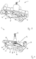
- the parking lock can have its own housing as a parking lock housing.
- the parking lock housing then either forms a common overall housing with the transmission housing, or the parking lock housing is arranged within the transmission housing.
- the parking lock can be without its own housing, so that the housing for the parking lock is the transmission housing itself.
- the parking lock 1 comprises locking teeth 2, which have a number of recesses 3 on its circumference.
- Another central component of the parking lock 1 is a pawl 4 which is arranged pivotably about an axis of rotation a.
- the pawl 4 can be seen in a downward (in the direction of the ratchet 2) position, in which a ratchet tooth 5 of the ratchet 4 engages in one of the recesses 3 of the ratchet 2 and thus locks the arrangement.
- the parking lock 1 is locked or unlocked via an actuator 6, which is indicated here as a shaft that rotates about an axis of rotation c for locking or unlocking.
- the gear element 7 comprises a linearly displaceable locking box 12 in which three rollers 13, 14 and 15 are mounted.
- the roller 13 can make contact with a ramp 17 (see Fig. Fig. 1 ), which is formed on the pawl 4.
- the transmission element 7 comprises a crank mechanism 8 with which a part 9 of the transmission element 7 can be moved linearly.
- a rod 16 is arranged between the part 9 and the locking box 12, so that a linear movement of the part 9 is transmitted to the locking box 12.
- the rod 16 is surrounded by a compression spring 20 which pretensions the pawl 4 and holds it in the locked position.
- the spa drive 8 has a crank 10 and a connecting rod 11 which are articulated to one another.
- the crank 10 is connected non-rotatably to the actuator 6.
- the connecting rod 11 is articulated to the part 9.
- roller 13 rolls on the pawl 4, while the rollers 14, 15 roll on the reinforcement 27.
- the reinforcement 27 is designed as a flat, hardened sheet steel and makes contact with the housing 21 of the parking lock 1 on the rear side.
- the two rollers 14, 15 on the housing side are needle-mounted to minimize friction and form support rollers.
- the third roller 13 that rolls on the pawl is a full roller.
- the locking box 12 has two elongated side parts 22, 23, which are preferably made as stamped sheet metal parts. Both side parts 22, 23 are connected at the end by two transverse parts 24, 25. The transverse parts 24, 25 are also preferably produced as stamped sheet metal parts. The side parts 22, 23 and the transverse parts 24, 25 can be riveted to one another.
- the locking box 12 carries a toothed drive segment 26 and guide rollers 28.
- the guide rollers 28 are placed in such a way that they are in the optimal flow of force to the drive pinion of the actuator 6.
- the locking box 12 also has the compression spring 20, which is guided on the drive tooth segment 26. It also takes up the axes of the support rollers 14, 15 and guides them axially.
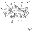
- the pawl 4 has a pawl recess 29 into which an engagement means 30 engages.
- the pawl recess 29 is designed as an elongated hole, and the engagement means 30 is designed as a bolt.
- the parking lock has a housing 21 in which the engagement means 30 is arranged in a stationary manner.
- the engagement means 30 and the pawl recess 29 form a loss protection.
- the pawl 4 is actuated via a roller 13, 14, 15, the pawl 4 being pretensioned against the roller 13, 14, 15 by a pretensioning means.
- the pretensioning means is designed as a lock 31.
- the lock 31 is arranged in the housing 21 of the parking lock and is preloaded against the pawl 4 with a ball 32. With respect to the pivot point, the locking device 31 is arranged on the side of the roller 13 facing away from the locking pawl 4.
Landscapes
- Engineering & Computer Science (AREA)
- General Engineering & Computer Science (AREA)
- Mechanical Engineering (AREA)
- Transportation (AREA)
- Gear-Shifting Mechanisms (AREA)
- Braking Arrangements (AREA)
Description
- Die Erfindung betrifft eine Parksperre für ein Kraftfahrzeug, wobei die Parksperre aufweist: eine Sperrklinke, die um eine Drehachse schwenkbar angeordnet ist und einen Klinkenzahn aufweist, der zum formschlüssigen Eingriff in ein Parksperrenrad ausgebildet ist, einen Aktuator zur Betätigung der Sperrklinke, so dass diese reversibel mit ihrem Klinkenzahn in Eingriff mit dem Parksperrenrad gebracht werden kann.
- Eine Parksperre ist aus der
DE 10 2010 053 857 A1 bekannt. Eine ähnliche Lösung zeigt dieDE 10 2011 080 498 A1 . Bei der letztgenannten Lösung kommt als mechanisches Getriebeelement zur Übertragung der Bewegung des Aktuators auf die Sperrklinke ein Planetenwälzgetriebe zum Einsatz. Damit ist es möglich, relativ hohe Übertragungskräfte zu realisieren. Weitere Parksperren sind inUS 6 279 713 B1 undEP 0 950 589 A2 gezeigt. - Beim Parken eines Fahrzeugs beispielsweise an einem Hang erzeugt das Fahrzeuggewicht, abhängig vom Raddurchmesser, von der Getriebeübersetzung und vom Radius des Sperrrads (Sperrverzahnung) eine Kraft auf die geschlossene Klinke und somit wiederrum auf den Parksperrenmechanismus. Beim Entriegeln der Parksperre am Hang muss somit diese anliegende Kraft überwunden werden.
- Die Kräfte müssen sicher abgestützt werden, andererseits sollen die Parksperre und das Getriebe möglichst leicht bauen. Im Stand der Technik wird der Parksperrenhebel als Sperrklinke im Getriebegehäuse einzeln montiert und angefedert. Die Montage ist aufwändig und hat zur Folge, dass die Sperrklinke erst nach der Montage gesichert ist.
- Der vorliegenden Erfindung liegt die Aufgabe zugrunde, eine gewichtsreduzierte Parksperre zu realisieren, die eine leichte und kostengünstige Montage erlaubt.
- Die Aufgabe wird durch eine Parksperre gemäß Anspruch 1 gelöst. Die Sperrklinke weist dazu eine Klinkenausnehmung auf, die auch als Durchgangsausnehmung ausgebildet sein kann, in die ein Eingriffsmittel eingreift. Durch die Klinkenausnehmung baut die Sperrklinke leicht, und das Eingriffsmittel kann durch Eingreifen in die Klinkenausnehmung diese am Gehäuse sichern. Eine externe Halterung der Sperrklinke ist nicht erforderlich. Vorteilhafterweise kann die Sperrklinke durch das Eingriffsmittel auch schon vorgespannt vormontiert werden.
- Der Eingriff des Eingriffsmittels in den Klinkenkörper erfordert keine gesonderte Funktionsflächenbearbeitung der Sperrklinke. Das Eingriffsmittel haltert die Sperrklinke und sichert sie gegen ein Verlieren. Dazu ist es beispielsweise mit dem Gehäuse fest verbunden.
- In einer Ausgestaltung ist das Eingriffsmittel als ein Bolzen ausgebildet. Mit einer runden Außenkontur kann er gegebenenfalls reibungsarm in der Klinkenausnehmung der Sperrklinke gleiten, wenn diese betätigt wird. Alternativ ist die Klinkenausnehmung so groß, dass das Eingriffsmittel beim Betätigen nicht an deren Wände stößt. Die Klinkenausnehmung ist vorzugsweise als ein Langloch ausgebildet, das dem Bolzen einen Bewegungsspielraum ermöglicht.
- In einer Weiterbildung weist das Langloch entlang seiner Länge keine konstante Breite auf, sondern eine veränderliche. Damit ist es an die Kontur der Sperrklinke gut anpassbar.
- Die Parksperre kann in verschiedenen Arten von Getrieben verbaut werden. Beispielsweise eignet sie sich für Kraftfahrzeuge mit manuellen Getrieben, mit automatisierten oder automatischen Getrieben oder für Getriebe von Elektrofahrzeugen.
- Die Parksperre kann ein eigenes Gehäuse als Parksperrengehäuse aufweisen. Das Parksperrengehäuse bildet dann mit dem Getriebegehäuse entweder ein gemeinsames Gesamtgehäuse, oder das Parksperrengehäuse ist innerhalb des Getriebegehäuses angeordnet. Alternativ kann die Parksperre ohne eigenes Gehäuse sein, so dass das Gehäuse für die Parksperre das Getriebegehäuse selbst ist.
- In den Figuren ist ein Ausführungsbeispiel der Erfindung dargestellt. Es zeigen:
- Figur 1
- die wesentlichen Bauteile einer ersten erfindungsgemäßen Parksperre ohne ein Gehäuse im Querschnitt,
- Figur 2
- die Parksperre gemäß
Figur 1 mit einem zusätzlichen Gehäuse in einer Aufsicht, - Figur 3
- die Parksperre gemäß
Figur 2 mit dem zusätzlichen Gehäuse in einer perspektivischen Schrägansicht, - Figur 4
- die Parksperre gemäß
Figur 3 ohne das zusätzliche Gehäuse in der gleichen perspektivischen Schrägansicht, - Figur 5
- die Parksperre gemäß
Figur 4 in einer anderen perspektivischen Schrägansicht ohne eine Armierung und - Figur 6
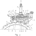
- eine Parksperre im Querschnitt ohne das Eingriffmittel.
- In den
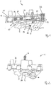
Figuren 1 bis 6 sind zwei Parksperren 1 dargestellt, wobei nur die wesentlichen Funktionsteile gezeigt sind. Abdeckungen und Anbindungsbauteile der Anordnung sind aus Gründen der Übersichtlichkeit weggelassen. Nachfolgend werden die erfindungsrelevanten Merkmale beschrieben, die auf einem grundsätzlichen Baukonzept einer Parksperre basieren, wie sie in der oben genanntenDE 10 2010 053 857 A1 undDE 10 2011 080 498 A1 der Anmelderin im Detail erläutert sind. Auf diese vorbekannten Lösungen wird insofern ausdrücklich Bezug genommen, um betreffend das grundsätzliche Funktionsprinzip einer Parksperre Wiederholungen zu vermeiden. - Generell umfasst die Parksperre 1 eine Sperrverzahnung 2, die eine Anzahl Ausnehmungen 3 an ihrem Umfang aufweist. Weiteres zentrales Bauteil der Parksperre 1 ist eine Sperrklinke 4, die um eine Drehachse a schwenkbar angeordnet ist.
- In
Figur 6 ist die Sperrklinke 4 in einer nach unten (in Richtung auf die Sperrverzahnung 2 zu) gerichteten Stellung zu sehen, in der ein Klinkenzahn 5 der Sperrklinke 4 in eine der Ausnehmungen 3 der Sperrverzahnung 2 eingreift und so die Anordnung verriegelt. - Die Verriegelung bzw. Entriegelung der Parksperre 1 erfolgt über einen Aktuator 6, der hier als Welle angedeutet ist, die für das Ver- bzw. Entriegeln um eine Drehachse c dreht.
- Die Übertragung der Bewegung des Aktuators 6 auf die Sperrklinke 4 erfolgt mittels eines Getriebeelements 7. Wie bei den genannten vorbekannten Lösungen, umfasst das Getriebeelement 7 einen linearverschieblichen Verriegelungskasten 12, in dem drei Rollen 13, 14 und 15 gelagert sind.
- Die Rolle 13 kann dabei Kontakt mit einer Rampe 17 nehmen (s.
Fig. 1 ), die an der Sperrklinke 4 ausgebildet ist. Bei linearer Bewegung des Verriegelungskastens 12 wird folglich die Sperrklinke 4 verschwenkt. - Im Falle der
Figur 6 umfasst das Getriebeelement 7 einen Kurbeltrieb 8, mit dem ein Teil 9 des Getriebeelements 7 linear bewegt werden kann. Zwischen dem Teil 9 und dem Verriegelungskasten 12 ist eine Stange 16 angeordnet, so dass sich eine lineare Bewegung des Teils 9 auf den Verriegelungskasten 12 überträgt. Die Stange 16 ist von einer Druckfeder 20 umschlossen, die die Sperrklinke 4 vorspannt und in der verriegelten Position hält. Der Kurbeitrieb 8 hat dabei eine Kurbel 10 und einen Pleuel 11, die gelenkig miteinander verbunden sind. Die Kurbel 10 ist mit dem Aktuator 6 drehfest verbunden. Der Pleuel 11 ist mit dem Teil 9 gelenkig verbunden. - Wird nun der Aktuator 6 betrieben, d. h. erfolgt eine Drehung um die Achse c, bewegt sich die Kurbel 10 entsprechend mit und zieht das Pleuel 11 mit. Mit dem Kurbeltrieb 8 kann - aufgrund der Eigenschaft eines Kurbeltriebs - nun bei gleichem, kleinen anliegenden Drehmoment am Aktuator 6 anfangs eine große Kraft zum Entriegeln realisiert werden, ohne den Gesamtstellweg zu reduzieren. Gegen zunehmenden Stellwinkel bzw. -weg nimmt die Kraft dann ab, was in diesem Fall aber nicht stört, da eine große Kraft nur anfangs benötigt wird, bis (in diesem Fall) die Rolle 13 den Hochpunkt der Rampe 17 der Sperrklinke 4 erreicht hat und die Verriegelung der Sperrklinke durch die Rolle 13 somit aufgehoben wird.
- Wie
Figur 1 zu entnehmen ist, weist die Schwenkachse b der scharnierartigen Verbindung zwischen der Kurbel 10 und dem Pleuel 11 in vertikaler Richtung, während die Drehachse a der Sperrklinke 4 in horizontale Richtung weist. Projiziert man demgemäß die Schwenkachse b auf die Drehachse a, sind diese beiden Achsen zueinander rechtwinklig ausgerichtet. - Wie insbesondere aus
Figur 1 zu entnehmen ist, wälzt die Rolle 13 auf der Sperrklinke 4 ab, während die Rollen 14, 15 auf der Armierung 27 abrollen. Die Armierung 27 ist als ein ebenes, gehärtetes Stahlblech ausgebildet und kontaktiert rückseitig das Gehäuse 21 der Parksperre 1. - In der dargestellten Ausführungsform sind die beiden gehäuseseitigen Rollen 14, 15 zur Reibungsminimierung nadelgelagert und bilden Stützrollen aus. Die dritte Rolle 13, die auf der Sperrklinke abrollt, ist eine Vollrolle.
- Die Rollen sind in einem Verriegelungskasten 12 integriert. Der Verriegelungskasten 12 weist zwei längliche Seitenteile 22, 23 auf, die vorzugsweise als Blechstanzteile hergestellt sind. Beide Seitenteile 22, 23 sind durch zwei Querteile 24, 25 stirnseitig verbunden. Auch die Querteile 24, 25 sind vorzugsweise als Blechstanzteile hergestellt. Die Seitenteile 22, 23 und die Querteile 24, 25 können miteinander vernietet sein.
- Der Verriegelungskasten 12 trägt ein Antriebszahnsegment 26 sowie Führungsrollen 28. Die Führungsrollen 28 sind so platziert, dass diese im optimalen Kraftfluss zum Antriebsritzel des Aktuators 6 stehen.
- Der Verriegelungskasten 12 weist ferner die Druckfeder 20 auf, die auf dem Antriebszahnsegment 26 geführt ist. Er nimmt auch die Achsen der Stützrollen 14, 15 auf und führt diese axial.
- Die Sperrklinke 4 weist eine Klinkenausnehmung 29 auf, in die ein Eingriffsmittel 30 eingreift.
- Die Klinkenausnehmung 29 ist als ein Langloch ausgebildet, und das Eingriffsmittel 30 ist als ein Bolzen ausgebildet.
- Die Parksperre weist ein Gehäuse 21 auf, in dem das Eingriffsmittel 30 ortsfest angeordnet ist.
- Das Eingriffsmittel 30 und die Klinkenausnehmung 29 bilden eine Verliersicherung.
- Die Sperrklinke 4 ist über eine Rolle 13, 14, 15 betätigt, wobei die Sperrklinke 4 durch ein Vorspannmittel gegen die Rolle 13, 14, 15 vorgespannt ist.
- Das Vorspannmittel ist als eine Arretierung 31 ausgebildet. Die Arretierung 31 ist im Gehäuse 21 der Parksperre angeordnet und mit einer Kugel 32 gegen die Sperrklinke 4 vorgespannt. Die Arretierung 31 ist in Bezug auf den Drehpunkt auf der der Sperrklinke 4 abgewandten Seite von der Rolle 13 angeordnet.
-
- 1
- Parksperre
- 2
- Sperrverzahnung
- 3
- Ausnehmung
- 4
- Sperrklinke
- 5
- Klinkenzahn
- 6
- Aktuator
- 7
- Getriebeelement
- 8
- Kurbeltrieb
- 9
- Teils des Getriebeelements
- 10
- Kurbel
- 11
- Pleuel
- 12
- Verriegelungskasten
- 13
- Rolle
- 14
- Rolle
- 15
- Rolle
- 16
- Stange
- 17
- Rampe
- 20
- Druckfeder
- 21
- Gehäuse
- 22
- Seitenteil
- 23
- Seitenteil
- 24
- Querteil
- 25
- Querteil
- 26
- Antriebszahnsegment
- 27
- Armierung
- 28
- Führungsrolle
- 29
- Klinkenausnehmung
- 30
- Eingriffsmittel
- 31
- Arretierung
- 32
- Kugel
- a
- Drehachse der Sperrklinke
- b
- Schwenkachse der Verbindung zwischen Kurbel und Pleuel
- c
- Drehachse des Aktuators
Claims (7)
- Parksperre (1) für ein Kraftfahrzeug, wobei die Parksperre (1) aufweist:- eine Sperrklinke (4), die um eine Drehachse (a) schwenkbar angeordnet ist und einen Klinkenzahn (5) aufweist, der zum formschlüssigen Eingriff in ein Parksperrenrad ausgebildet ist, wobeidie Sperrklinke (4) eine Klinkenausnehmung (29) aufweist, in die ein Eingriffsmittel (30) eingreift, dadurch gekennzeichnet, dass die Sperrklinke (4) über eine Rolle (13, 14, 15) betätigt ist, wobei die Sperrklinke (4) durch ein Vorspannmittel gegen die Rolle (13, 14, 15) vorgespannt ist.
- Parksperre (1) nach Anspruch 1, dadurch gekennzeichnet, dass die Klinkenausnehmung (29) als ein Langloch und das Eingriffsmittel (30) als ein Bolzen ausgebildet sind.
- Parksperre (1) nach Anspruch 1 oder 2, dadurch gekennzeichnet, dass die Parksperre (1) ein Gehäuse (21) aufweist, in dem das Eingriffsmittel (30) ortsfest angeordnet ist.
- Parksperre (1) nach einem der vorhergehenden Ansprüche, dadurch gekennzeichnet, dass das Eingriffsmittel (30) und die Klinkenausnehmung (29) eine Verliersicherung bilden.
- Parksperre (1)nach einem der vorhergehenden Ansprüche, dadurch gekennzeichnet, dass das Vorspannmittel als eine Arretierung (31) ausgebildet ist.
- Parksperre (1) nach Anspruch 5, dadurch gekennzeichnet, dass die Arretierung (31) im Gehäuse (21) der Parksperre angeordnet ist und mit einer Kugel (32) gegen die Sperrklinke (4) vorgespannt ist.
- Parksperre (1) nach Anspruch 2, dadurch gekennzeichnet, dass die Langlochbreite sich über dessen Länge ändert.
Applications Claiming Priority (2)
| Application Number | Priority Date | Filing Date | Title |
|---|---|---|---|
| DE102016223473 | 2016-11-25 | ||
| PCT/DE2017/100996 WO2018108204A1 (de) | 2016-11-25 | 2017-11-23 | Parksperre für ein kraftfahrzeug |
Publications (2)
| Publication Number | Publication Date |
|---|---|
| EP3545207A1 EP3545207A1 (de) | 2019-10-02 |
| EP3545207B1 true EP3545207B1 (de) | 2021-01-06 |
Family
ID=61899015
Family Applications (1)
| Application Number | Title | Priority Date | Filing Date |
|---|---|---|---|
| EP17859363.8A Active EP3545207B1 (de) | 2016-11-25 | 2017-11-23 | Parksperre für ein kraftfahrzeug |
Country Status (4)
| Country | Link |
|---|---|
| EP (1) | EP3545207B1 (de) |
| CN (1) | CN109923326B (de) |
| DE (1) | DE102017127358A1 (de) |
| WO (1) | WO2018108204A1 (de) |
Families Citing this family (11)
| Publication number | Priority date | Publication date | Assignee | Title |
|---|---|---|---|---|
| DE102018126456A1 (de) | 2017-10-25 | 2019-04-25 | Schaeffler Technologies AG & Co. KG | Schaltvorrichtung und Verfahren zur Montage einer Schaltvorrichtung |
| DE102018130315A1 (de) | 2018-11-21 | 2019-10-24 | Schaeffler Technologies AG & Co. KG | Parksperre für ein Kraftfahrzeug |
| CN112912649B (zh) * | 2018-11-21 | 2022-08-09 | 舍弗勒技术股份两合公司 | 驻车锁止装置及其组装方法 |
| CN114423976B (zh) * | 2019-09-13 | 2024-06-07 | 莱纳玛公司 | 紧凑的驻车锁组件 |
| CN112537280B (zh) * | 2019-09-23 | 2024-03-22 | 舍弗勒技术股份两合公司 | 驻车系统 |
| DE202020005515U1 (de) | 2020-08-27 | 2021-06-25 | Schaeffler Technologies AG & Co. KG | Parksperrenvorrichtung für ein Fahrzeug |
| KR102793309B1 (ko) * | 2021-11-30 | 2025-04-09 | 주식회사 네오오토 | 랙 앤 피니언 구조를 갖는 차량용 파킹 장치를 포함하는 차량용 변속기 |
| KR102724539B1 (ko) * | 2021-12-22 | 2024-11-04 | 삼보모터스주식회사 | 비정상 파킹락 방지부가 구비된 전동 파킹락 장치 |
| DE102022103753B4 (de) | 2022-02-17 | 2023-12-21 | Schaeffler Technologies AG & Co. KG | Parksperre für ein Fahrzeuggetriebe |
| EP4275854A1 (de) * | 2022-05-12 | 2023-11-15 | Festool GmbH | Blockierelement für eine notbremseinheit einer sägevorrichtung sowie sägevorrichtung |
| DE102022119719A1 (de) * | 2022-08-05 | 2024-02-08 | Schaeffler Technologies AG & Co. KG | Parksperre und Verfahren zu ihrer Montage |
Family Cites Families (10)
| Publication number | Priority date | Publication date | Assignee | Title |
|---|---|---|---|---|
| FR2691515B1 (fr) * | 1992-05-19 | 1998-04-10 | Renault | Dispositif de commande de frein de parking. |
| DE19816801C2 (de) * | 1998-04-16 | 2001-03-22 | Daimler Chrysler Ag | Blockiereinrichtung für ein Fahrzeug |
| BR0006946A (pt) * | 1999-07-28 | 2001-07-31 | Luk Lamellen & Kupplungsbau | Caixa de mudança para um veìculo a motor |
| US6279713B1 (en) * | 2000-02-17 | 2001-08-28 | Visteon Global Technologies, Inc. | Parking pawl assembly |
| DE10144056B4 (de) * | 2001-09-07 | 2005-09-01 | Ina-Schaeffler Kg | Parksperre für ein Automatikgetriebe eines Kraftfahrzeuges |
| DE10307109A1 (de) * | 2003-02-19 | 2004-09-02 | ZF Lemförder Metallwaren AG | Schaltvorrichtung für ein automatisches Kraftfahrzeuggetriebe mit einer Sperrvorrichtung für den Wählhebel |
| FR2934341B1 (fr) * | 2008-07-28 | 2011-01-21 | Renault Sas | Dispositif de blocage de l'arbre de sortie d'un moteur de vehicule automobile. |
| DE102010053857A1 (de) | 2010-12-08 | 2012-06-14 | Schaeffler Technologies Gmbh & Co. Kg | Parksperre |
| DE102011086239A1 (de) * | 2010-12-08 | 2012-06-14 | Schaeffler Technologies Gmbh & Co. Kg | Parksperre |
| DE102011080498A1 (de) | 2011-08-05 | 2013-02-07 | Schaeffler Technologies AG & Co. KG | Parksperre |
-
2017
- 2017-11-23 CN CN201780069095.4A patent/CN109923326B/zh active Active
- 2017-11-23 EP EP17859363.8A patent/EP3545207B1/de active Active
- 2017-11-23 WO PCT/DE2017/100996 patent/WO2018108204A1/de not_active Ceased
- 2017-11-23 DE DE102017127358.1A patent/DE102017127358A1/de not_active Withdrawn
Non-Patent Citations (1)
| Title |
|---|
| None * |
Also Published As
| Publication number | Publication date |
|---|---|
| EP3545207A1 (de) | 2019-10-02 |
| DE102017127358A1 (de) | 2018-05-30 |
| WO2018108204A1 (de) | 2018-06-21 |
| CN109923326B (zh) | 2021-04-27 |
| CN109923326A (zh) | 2019-06-21 |
Similar Documents
| Publication | Publication Date | Title |
|---|---|---|
| EP3545207B1 (de) | Parksperre für ein kraftfahrzeug | |
| DE102018132470B4 (de) | Parksperre für ein Kraftfahrzeug | |
| EP3545217B1 (de) | Parksperre für ein kraftfahrzeug | |
| DE112007001663B4 (de) | Drehschwingungsdämpfer | |
| DE102017127213A1 (de) | Parksperre für ein Kraftfahrzeug | |
| EP3472497B1 (de) | Parksperre für ein kraftfahrzeug | |
| DE102018129314A1 (de) | Parksperre für ein Getriebe | |
| DE102018130765B4 (de) | Parksperrenvorrichtung für ein Getriebe mit einem Parksperrenrad | |
| DE102016220531A1 (de) | Lenksäule mit adaptiver Energieabsorptionsvorrichtung für ein Kraftfahrzeug | |
| WO2018095477A1 (de) | Parksperre für ein kraftfahrzeug | |
| DE102016220533A1 (de) | Lenksäule mit Energieabsorptionsvorrichtung für ein Kraftfahrzeug | |
| DE102018131099A1 (de) | Parksperrengehäuse | |
| DE102018220503A1 (de) | Parksperre und ein Getriebe mit der Parksperre | |
| DE102007048208A1 (de) | Lenksäule für ein Kraftfahrzeug | |
| EP2037067B1 (de) | Antriebseinrichtung für eine Kraftfahrzeugtür | |
| DE102019134517A1 (de) | Sperrklinke für eine Parksperre | |
| DE102013002165A1 (de) | Parksperrenanordnung für ein Kraftfahrzeug | |
| WO2020108699A1 (de) | Parksperre für ein kraftfahrzeug | |
| DE102010028029A1 (de) | Verbindung zwischen der Rastenscheibe und der Verbindungsstange einer Parksperre eines Kraftfahrzeugs | |
| DE10234371B4 (de) | Blockierbare Feststellvorrichtung | |
| WO2017216053A1 (de) | Längseinsteller für einen fahrzeugsitz und fahrzeugsitz | |
| DE102023112433A1 (de) | Parksperrvorrichtung mit einem Federführungsmittel | |
| DE102023207164A1 (de) | Parksperrenanordnung für ein Kraftfahrzeug | |
| WO2025026763A1 (de) | Parksperrenanordnung | |
| WO2025026766A1 (de) | Parksperrenanordnung |
Legal Events
| Date | Code | Title | Description |
|---|---|---|---|
| STAA | Information on the status of an ep patent application or granted ep patent |
Free format text: STATUS: UNKNOWN |
|
| STAA | Information on the status of an ep patent application or granted ep patent |
Free format text: STATUS: THE INTERNATIONAL PUBLICATION HAS BEEN MADE |
|
| PUAI | Public reference made under article 153(3) epc to a published international application that has entered the european phase |
Free format text: ORIGINAL CODE: 0009012 |
|
| STAA | Information on the status of an ep patent application or granted ep patent |
Free format text: STATUS: REQUEST FOR EXAMINATION WAS MADE |
|
| 17P | Request for examination filed |
Effective date: 20190625 |
|
| AK | Designated contracting states |
Kind code of ref document: A1 Designated state(s): AL AT BE BG CH CY CZ DE DK EE ES FI FR GB GR HR HU IE IS IT LI LT LU LV MC MK MT NL NO PL PT RO RS SE SI SK SM TR |
|
| AX | Request for extension of the european patent |
Extension state: BA ME |
|
| DAV | Request for validation of the european patent (deleted) | ||
| DAX | Request for extension of the european patent (deleted) | ||
| GRAP | Despatch of communication of intention to grant a patent |
Free format text: ORIGINAL CODE: EPIDOSNIGR1 |
|
| STAA | Information on the status of an ep patent application or granted ep patent |
Free format text: STATUS: GRANT OF PATENT IS INTENDED |
|
| INTG | Intention to grant announced |
Effective date: 20200918 |
|
| GRAS | Grant fee paid |
Free format text: ORIGINAL CODE: EPIDOSNIGR3 |
|
| GRAA | (expected) grant |
Free format text: ORIGINAL CODE: 0009210 |
|
| STAA | Information on the status of an ep patent application or granted ep patent |
Free format text: STATUS: THE PATENT HAS BEEN GRANTED |
|
| AK | Designated contracting states |
Kind code of ref document: B1 Designated state(s): AL AT BE BG CH CY CZ DE DK EE ES FI FR GB GR HR HU IE IS IT LI LT LU LV MC MK MT NL NO PL PT RO RS SE SI SK SM TR |
|
| REG | Reference to a national code |
Ref country code: GB Ref legal event code: FG4D Free format text: NOT ENGLISH |
|
| REG | Reference to a national code |
Ref country code: AT Ref legal event code: REF Ref document number: 1352703 Country of ref document: AT Kind code of ref document: T Effective date: 20210115 Ref country code: CH Ref legal event code: EP |
|
| REG | Reference to a national code |
Ref country code: DE Ref legal event code: R096 Ref document number: 502017009019 Country of ref document: DE |
|
| REG | Reference to a national code |
Ref country code: IE Ref legal event code: FG4D Free format text: LANGUAGE OF EP DOCUMENT: GERMAN |
|
| REG | Reference to a national code |
Ref country code: NL Ref legal event code: MP Effective date: 20210106 |
|
| REG | Reference to a national code |
Ref country code: LT Ref legal event code: MG9D |
|
| PG25 | Lapsed in a contracting state [announced via postgrant information from national office to epo] |
Ref country code: NO Free format text: LAPSE BECAUSE OF FAILURE TO SUBMIT A TRANSLATION OF THE DESCRIPTION OR TO PAY THE FEE WITHIN THE PRESCRIBED TIME-LIMIT Effective date: 20210406 Ref country code: PT Free format text: LAPSE BECAUSE OF FAILURE TO SUBMIT A TRANSLATION OF THE DESCRIPTION OR TO PAY THE FEE WITHIN THE PRESCRIBED TIME-LIMIT Effective date: 20210506 Ref country code: FI Free format text: LAPSE BECAUSE OF FAILURE TO SUBMIT A TRANSLATION OF THE DESCRIPTION OR TO PAY THE FEE WITHIN THE PRESCRIBED TIME-LIMIT Effective date: 20210106 Ref country code: HR Free format text: LAPSE BECAUSE OF FAILURE TO SUBMIT A TRANSLATION OF THE DESCRIPTION OR TO PAY THE FEE WITHIN THE PRESCRIBED TIME-LIMIT Effective date: 20210106 Ref country code: GR Free format text: LAPSE BECAUSE OF FAILURE TO SUBMIT A TRANSLATION OF THE DESCRIPTION OR TO PAY THE FEE WITHIN THE PRESCRIBED TIME-LIMIT Effective date: 20210407 Ref country code: BG Free format text: LAPSE BECAUSE OF FAILURE TO SUBMIT A TRANSLATION OF THE DESCRIPTION OR TO PAY THE FEE WITHIN THE PRESCRIBED TIME-LIMIT Effective date: 20210406 Ref country code: LT Free format text: LAPSE BECAUSE OF FAILURE TO SUBMIT A TRANSLATION OF THE DESCRIPTION OR TO PAY THE FEE WITHIN THE PRESCRIBED TIME-LIMIT Effective date: 20210106 |
|
| PG25 | Lapsed in a contracting state [announced via postgrant information from national office to epo] |
Ref country code: RS Free format text: LAPSE BECAUSE OF FAILURE TO SUBMIT A TRANSLATION OF THE DESCRIPTION OR TO PAY THE FEE WITHIN THE PRESCRIBED TIME-LIMIT Effective date: 20210106 Ref country code: LV Free format text: LAPSE BECAUSE OF FAILURE TO SUBMIT A TRANSLATION OF THE DESCRIPTION OR TO PAY THE FEE WITHIN THE PRESCRIBED TIME-LIMIT Effective date: 20210106 Ref country code: PL Free format text: LAPSE BECAUSE OF FAILURE TO SUBMIT A TRANSLATION OF THE DESCRIPTION OR TO PAY THE FEE WITHIN THE PRESCRIBED TIME-LIMIT Effective date: 20210106 Ref country code: SE Free format text: LAPSE BECAUSE OF FAILURE TO SUBMIT A TRANSLATION OF THE DESCRIPTION OR TO PAY THE FEE WITHIN THE PRESCRIBED TIME-LIMIT Effective date: 20210106 |
|
| PG25 | Lapsed in a contracting state [announced via postgrant information from national office to epo] |
Ref country code: IS Free format text: LAPSE BECAUSE OF FAILURE TO SUBMIT A TRANSLATION OF THE DESCRIPTION OR TO PAY THE FEE WITHIN THE PRESCRIBED TIME-LIMIT Effective date: 20210506 |
|
| REG | Reference to a national code |
Ref country code: DE Ref legal event code: R097 Ref document number: 502017009019 Country of ref document: DE |
|
| PG25 | Lapsed in a contracting state [announced via postgrant information from national office to epo] |
Ref country code: CZ Free format text: LAPSE BECAUSE OF FAILURE TO SUBMIT A TRANSLATION OF THE DESCRIPTION OR TO PAY THE FEE WITHIN THE PRESCRIBED TIME-LIMIT Effective date: 20210106 Ref country code: EE Free format text: LAPSE BECAUSE OF FAILURE TO SUBMIT A TRANSLATION OF THE DESCRIPTION OR TO PAY THE FEE WITHIN THE PRESCRIBED TIME-LIMIT Effective date: 20210106 Ref country code: SM Free format text: LAPSE BECAUSE OF FAILURE TO SUBMIT A TRANSLATION OF THE DESCRIPTION OR TO PAY THE FEE WITHIN THE PRESCRIBED TIME-LIMIT Effective date: 20210106 |
|
| PLBE | No opposition filed within time limit |
Free format text: ORIGINAL CODE: 0009261 |
|
| STAA | Information on the status of an ep patent application or granted ep patent |
Free format text: STATUS: NO OPPOSITION FILED WITHIN TIME LIMIT |
|
| PG25 | Lapsed in a contracting state [announced via postgrant information from national office to epo] |
Ref country code: DK Free format text: LAPSE BECAUSE OF FAILURE TO SUBMIT A TRANSLATION OF THE DESCRIPTION OR TO PAY THE FEE WITHIN THE PRESCRIBED TIME-LIMIT Effective date: 20210106 Ref country code: SK Free format text: LAPSE BECAUSE OF FAILURE TO SUBMIT A TRANSLATION OF THE DESCRIPTION OR TO PAY THE FEE WITHIN THE PRESCRIBED TIME-LIMIT Effective date: 20210106 Ref country code: RO Free format text: LAPSE BECAUSE OF FAILURE TO SUBMIT A TRANSLATION OF THE DESCRIPTION OR TO PAY THE FEE WITHIN THE PRESCRIBED TIME-LIMIT Effective date: 20210106 |
|
| 26N | No opposition filed |
Effective date: 20211007 |
|
| PG25 | Lapsed in a contracting state [announced via postgrant information from national office to epo] |
Ref country code: ES Free format text: LAPSE BECAUSE OF FAILURE TO SUBMIT A TRANSLATION OF THE DESCRIPTION OR TO PAY THE FEE WITHIN THE PRESCRIBED TIME-LIMIT Effective date: 20210106 Ref country code: AL Free format text: LAPSE BECAUSE OF FAILURE TO SUBMIT A TRANSLATION OF THE DESCRIPTION OR TO PAY THE FEE WITHIN THE PRESCRIBED TIME-LIMIT Effective date: 20210106 |
|
| PG25 | Lapsed in a contracting state [announced via postgrant information from national office to epo] |
Ref country code: SI Free format text: LAPSE BECAUSE OF FAILURE TO SUBMIT A TRANSLATION OF THE DESCRIPTION OR TO PAY THE FEE WITHIN THE PRESCRIBED TIME-LIMIT Effective date: 20210106 |
|
| PG25 | Lapsed in a contracting state [announced via postgrant information from national office to epo] |
Ref country code: IS Free format text: LAPSE BECAUSE OF FAILURE TO SUBMIT A TRANSLATION OF THE DESCRIPTION OR TO PAY THE FEE WITHIN THE PRESCRIBED TIME-LIMIT Effective date: 20210506 |
|
| PG25 | Lapsed in a contracting state [announced via postgrant information from national office to epo] |
Ref country code: MC Free format text: LAPSE BECAUSE OF FAILURE TO SUBMIT A TRANSLATION OF THE DESCRIPTION OR TO PAY THE FEE WITHIN THE PRESCRIBED TIME-LIMIT Effective date: 20210106 |
|
| REG | Reference to a national code |
Ref country code: CH Ref legal event code: PL |
|
| GBPC | Gb: european patent ceased through non-payment of renewal fee |
Effective date: 20211123 |
|
| PG25 | Lapsed in a contracting state [announced via postgrant information from national office to epo] |
Ref country code: LU Free format text: LAPSE BECAUSE OF NON-PAYMENT OF DUE FEES Effective date: 20211123 Ref country code: BE Free format text: LAPSE BECAUSE OF NON-PAYMENT OF DUE FEES Effective date: 20211130 |
|
| REG | Reference to a national code |
Ref country code: BE Ref legal event code: MM Effective date: 20211130 |
|
| PG25 | Lapsed in a contracting state [announced via postgrant information from national office to epo] |
Ref country code: LI Free format text: LAPSE BECAUSE OF NON-PAYMENT OF DUE FEES Effective date: 20211130 Ref country code: CH Free format text: LAPSE BECAUSE OF NON-PAYMENT OF DUE FEES Effective date: 20211130 |
|
| PG25 | Lapsed in a contracting state [announced via postgrant information from national office to epo] |
Ref country code: IE Free format text: LAPSE BECAUSE OF NON-PAYMENT OF DUE FEES Effective date: 20211123 Ref country code: GB Free format text: LAPSE BECAUSE OF NON-PAYMENT OF DUE FEES Effective date: 20211123 |
|
| P01 | Opt-out of the competence of the unified patent court (upc) registered |
Effective date: 20230522 |
|
| PG25 | Lapsed in a contracting state [announced via postgrant information from national office to epo] |
Ref country code: NL Free format text: LAPSE BECAUSE OF NON-PAYMENT OF DUE FEES Effective date: 20210206 Ref country code: CY Free format text: LAPSE BECAUSE OF FAILURE TO SUBMIT A TRANSLATION OF THE DESCRIPTION OR TO PAY THE FEE WITHIN THE PRESCRIBED TIME-LIMIT Effective date: 20210106 |
|
| PG25 | Lapsed in a contracting state [announced via postgrant information from national office to epo] |
Ref country code: HU Free format text: LAPSE BECAUSE OF FAILURE TO SUBMIT A TRANSLATION OF THE DESCRIPTION OR TO PAY THE FEE WITHIN THE PRESCRIBED TIME-LIMIT; INVALID AB INITIO Effective date: 20171123 |
|
| REG | Reference to a national code |
Ref country code: AT Ref legal event code: MM01 Ref document number: 1352703 Country of ref document: AT Kind code of ref document: T Effective date: 20221123 |
|
| PG25 | Lapsed in a contracting state [announced via postgrant information from national office to epo] |
Ref country code: AT Free format text: LAPSE BECAUSE OF NON-PAYMENT OF DUE FEES Effective date: 20221123 |
|
| PG25 | Lapsed in a contracting state [announced via postgrant information from national office to epo] |
Ref country code: MK Free format text: LAPSE BECAUSE OF FAILURE TO SUBMIT A TRANSLATION OF THE DESCRIPTION OR TO PAY THE FEE WITHIN THE PRESCRIBED TIME-LIMIT Effective date: 20210106 |
|
| PG25 | Lapsed in a contracting state [announced via postgrant information from national office to epo] |
Ref country code: MT Free format text: LAPSE BECAUSE OF FAILURE TO SUBMIT A TRANSLATION OF THE DESCRIPTION OR TO PAY THE FEE WITHIN THE PRESCRIBED TIME-LIMIT Effective date: 20210106 |
|
| PGFP | Annual fee paid to national office [announced via postgrant information from national office to epo] |
Ref country code: DE Payment date: 20250121 Year of fee payment: 8 |
|
| PG25 | Lapsed in a contracting state [announced via postgrant information from national office to epo] |
Ref country code: TR Free format text: LAPSE BECAUSE OF FAILURE TO SUBMIT A TRANSLATION OF THE DESCRIPTION OR TO PAY THE FEE WITHIN THE PRESCRIBED TIME-LIMIT Effective date: 20210106 |
|
| PGFP | Annual fee paid to national office [announced via postgrant information from national office to epo] |
Ref country code: IT Payment date: 20251125 Year of fee payment: 9 |
|
| PGFP | Annual fee paid to national office [announced via postgrant information from national office to epo] |
Ref country code: FR Payment date: 20251126 Year of fee payment: 9 |