EP3545119B1 - Verfahren und vorrichtung zur fluidleckdetektion - Google Patents
Verfahren und vorrichtung zur fluidleckdetektion Download PDFInfo
- Publication number
- EP3545119B1 EP3545119B1 EP17874900.8A EP17874900A EP3545119B1 EP 3545119 B1 EP3545119 B1 EP 3545119B1 EP 17874900 A EP17874900 A EP 17874900A EP 3545119 B1 EP3545119 B1 EP 3545119B1
- Authority
- EP
- European Patent Office
- Prior art keywords
- hydrogen
- electrically conductive
- submerging
- conductive body
- fluid
- Prior art date
- Legal status (The legal status is an assumption and is not a legal conclusion. Google has not performed a legal analysis and makes no representation as to the accuracy of the status listed.)
- Active
Links
Images


Classifications
-
- G—PHYSICS
- G01—MEASURING; TESTING
- G01M—TESTING STATIC OR DYNAMIC BALANCE OF MACHINES OR STRUCTURES; TESTING OF STRUCTURES OR APPARATUS, NOT OTHERWISE PROVIDED FOR
- G01M3/00—Investigating fluid-tightness of structures
- G01M3/02—Investigating fluid-tightness of structures by using fluid or vacuum
- G01M3/04—Investigating fluid-tightness of structures by using fluid or vacuum by detecting the presence of fluid at the leakage point
-
- C—CHEMISTRY; METALLURGY
- C25—ELECTROLYTIC OR ELECTROPHORETIC PROCESSES; APPARATUS THEREFOR
- C25B—ELECTROLYTIC OR ELECTROPHORETIC PROCESSES FOR THE PRODUCTION OF COMPOUNDS OR NON-METALS; APPARATUS THEREFOR
- C25B1/00—Electrolytic production of inorganic compounds or non-metals
- C25B1/01—Products
- C25B1/02—Hydrogen or oxygen
- C25B1/04—Hydrogen or oxygen by electrolysis of water
-
- C—CHEMISTRY; METALLURGY
- C25—ELECTROLYTIC OR ELECTROPHORETIC PROCESSES; APPARATUS THEREFOR
- C25B—ELECTROLYTIC OR ELECTROPHORETIC PROCESSES FOR THE PRODUCTION OF COMPOUNDS OR NON-METALS; APPARATUS THEREFOR
- C25B9/00—Cells or assemblies of cells; Constructional parts of cells; Assemblies of constructional parts, e.g. electrode-diaphragm assemblies; Process-related cell features
- C25B9/70—Assemblies comprising two or more cells
- C25B9/73—Assemblies comprising two or more cells of the filter-press type
-
- F—MECHANICAL ENGINEERING; LIGHTING; HEATING; WEAPONS; BLASTING
- F22—STEAM GENERATION
- F22B—METHODS OF STEAM GENERATION; STEAM BOILERS
- F22B3/00—Other methods of steam generation; Steam boilers not provided for in other groups of this subclass
- F22B3/02—Other methods of steam generation; Steam boilers not provided for in other groups of this subclass involving the use of working media other than water
-
- G—PHYSICS
- G01—MEASURING; TESTING
- G01M—TESTING STATIC OR DYNAMIC BALANCE OF MACHINES OR STRUCTURES; TESTING OF STRUCTURES OR APPARATUS, NOT OTHERWISE PROVIDED FOR
- G01M3/00—Investigating fluid-tightness of structures
- G01M3/02—Investigating fluid-tightness of structures by using fluid or vacuum
- G01M3/04—Investigating fluid-tightness of structures by using fluid or vacuum by detecting the presence of fluid at the leakage point
- G01M3/20—Investigating fluid-tightness of structures by using fluid or vacuum by detecting the presence of fluid at the leakage point using special tracer materials, e.g. dye, fluorescent material, radioactive material
- G01M3/202—Investigating fluid-tightness of structures by using fluid or vacuum by detecting the presence of fluid at the leakage point using special tracer materials, e.g. dye, fluorescent material, radioactive material using mass spectrometer detection systems
- G01M3/205—Accessories or associated equipment; Pump constructions
-
- G—PHYSICS
- G01—MEASURING; TESTING
- G01M—TESTING STATIC OR DYNAMIC BALANCE OF MACHINES OR STRUCTURES; TESTING OF STRUCTURES OR APPARATUS, NOT OTHERWISE PROVIDED FOR
- G01M3/00—Investigating fluid-tightness of structures
- G01M3/40—Investigating fluid-tightness of structures by using electric means, e.g. by observing electric discharges
-
- Y—GENERAL TAGGING OF NEW TECHNOLOGICAL DEVELOPMENTS; GENERAL TAGGING OF CROSS-SECTIONAL TECHNOLOGIES SPANNING OVER SEVERAL SECTIONS OF THE IPC; TECHNICAL SUBJECTS COVERED BY FORMER USPC CROSS-REFERENCE ART COLLECTIONS [XRACs] AND DIGESTS
- Y02—TECHNOLOGIES OR APPLICATIONS FOR MITIGATION OR ADAPTATION AGAINST CLIMATE CHANGE
- Y02E—REDUCTION OF GREENHOUSE GAS [GHG] EMISSIONS, RELATED TO ENERGY GENERATION, TRANSMISSION OR DISTRIBUTION
- Y02E60/00—Enabling technologies; Technologies with a potential or indirect contribution to GHG emissions mitigation
- Y02E60/30—Hydrogen technology
- Y02E60/36—Hydrogen production from non-carbon containing sources, e.g. by water electrolysis
Definitions
- the present disclosure relates generally to leak detection devices and methods, and more specifically to devices and methods associated with generating a detection media used for leak detection in a fluid system.
- the visual vapor or smoke may be produced by heating mineral oil within a chamber to vaporize the mineral oil.
- precise heating temperatures for the mineral oil may be required.
- the magnitude of the heating temperature may vary depending on the test pressure. For instance, a test pressure of 551.58 kPa (80 PSI) may require a heating temperature within the chamber of 75-80 degrees Celsius to produce optimum production of vapor.
- the preheating delay could be as long as 8-12 minutes, depending on several factors such as ambient air temperature, compressed air temperature, flow rate of compressed air through the chamber, input voltage to the heating element, amount of mineral oil in the chamber, and the materials used to construct the chamber. Also, if cold air is running through the chamber, the cold air may cool the heater, thereby making the heater less effective. When the proper warm up cycle is achieved, the optimum amount of detectable signature vapor may be produced for the desired compressed air test pressure.
- the mineral oil is vaporized under proper conditions, there may be limitations as to the use of the vaporized mineral oil for visual identification of leaks.
- the oil particles that are vaporized to make visual vapor may not be able to get through a leak to allow for visual inspection.
- pressures are much higher such as 206.84 kPa (30 PSI) up to 1206.58 kPa (175 PSI) the vapor may not be visible because it is being transmitted through a leak point with such force it dissipates before it can be identified visually.
- a trace gas in conjunction with a gas detector can be a much more effective method of detecting and locating tiny leak as well as high pressure leaks. While the process of creating visual vapor may also create some hydrogen there are several factors that can complicate a leak detection process. First, if one uses a typical capillary device such as fiberglass with wicking properties, the higher pressures and temperatures may cause dieseling in the smoke chamber that is exacerbated by the tiny fiberglass fibers.
- a hydrogen over-pressure leak detection is known from WO 2015/169569 A1 and common hydrogen generation methods are known from US 4 339 324 A and US 2009/277800 A1 .
- the claimed invention is defined in independent claim 1.
- the method includes submerging at least a portion of an electrically conductive body in an electrolyte solution, with the electrically conductive body and electrolyte solution being in an internal chamber of a device.
- the method further includes directing an electrical signal to the electrically conductive body, causing a reaction between the electrically conductive body and the electrolyte solution to produce hydrogen.
- the method further includes injecting the hydrogen into the fluid system for leak detection.
- the injecting step may include injecting hydrogen into the fluid system at a pressure greater than 930.79 kPa (135 PSI), or at a pressure greater than 1034.21 kPa (150 PSI), or at a pressure between 1034.21-1378.95 kPa (150-200 PSI).
- the hydrogen may be produced less than 8 minutes after directing the electrical signal to the electrically conductive body. Hydrogen may be produced less than 1 minute after directing the electrical signal to the electrically conductive body.
- the temperature within the internal chamber during production of the hydrogen may be less than 75 degrees Celsius.
- the capillary device may be formed from a ceramic material.
- the hydrogen may be generated through electrolysis using distilled water, with the hydrogen being mixed with a pressurized gas and subsequently injected into a fluid system for testing the integrity of the fluid system.
- a hydrogen sniffer may be used to determine whether hydrogen is leaking from the fluid system to help identify the presence of the leak.
- Generating hydrogen through electrolysis may be much quicker than conventional methods of generating testing media, which are typically associated with a warm-up period, which may be unnecessary with the electrolysis method.
- the use of electrolysis may allow for increased testing pressures.
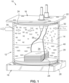
- the generating device 10 used to generate hydrogen and deliver the hydrogen to the fluid system for testing.
- the generating device 10 includes a housing 12 having an internal chamber 14.
- the housing 12 is comprised of an upper body 16, a lower body 18, and a sidewall 20 extending between the upper body 16 and lower body 18.
- the housing 12 may be portable and capable of being transported to allow for leak testing in different locations or at different facilities.
- the upper body 16 includes a quadrangular plate 22 and a circular element 24 extending from the quadrangular plate 22.
- the quadrangular plate 22 is sized and structured to extend radially outward from the circular element 24.
- the lower body 18 is configured similar to the upper body 16, with the lower body 18 including a quadrangular plate 26 and a circular element 28 extending from the quadrangular plate 26.
- the sidewall 20 may be in the form of a generally cylindrical sleeve, which receives the circular elements 24, 28 therein, and engages with the circular elements 24, 28 to create a fluid tight seal between the sidewall 20 and the circular elements 24, 28.
- the internal chamber 14 may be collectively defined by the circular elements 24, 28 and the sidewall 20. Seals, gaskets, o-rings, or the like may be used between the circular elements 24, 28 and the sidewall 20 to strengthen any fluid tight seal therebetween.
- the sidewall 20 includes an inlet opening 30 and an outlet opening 32 formed therein, with the inlet opening 30 being fluidly connectable with a source of pressurized fluid, and the outlet opening 32 being fluidly connectable to the fluid system that is to be tested.
- the pressurized fluid is received into the internal chamber 14 through the inlet opening 30, and mixed with the hydrogen generated within the internal chamber 14. Subsequently, the pressurized mixture flows through the outlet opening 32 and into the fluid system for leak detection.
- the upper body 16 and lower body 18 in the exemplary embodiment include quadrangular plates 22, 26 and circular elements 24, 28, it is understood that the shape and configuration of the upper and lower bodies 16, 18 is not limited thereto. In this respect, the upper and lower bodies 16, 18 may be a variety of different shapes and sizes without departing from the spirit and scope of the present disclosure. Likewise, the sidewall 20 is not limited to having a circular cross sectional configuration. Rather, it is contemplated that the sidewall 20 may formed in other shapes.
- the generating device 10 additionally includes a plurality of electrically conductive bodies 34 located within the internal chamber 14.
- the electrically conductive bodies 34 include a plurality of electrically conductive plates, which are placed on the circular element 28 of the lower body 18.
- Five electrically conductive plates 34 are included in the exemplary embodiment.
- the plates 34 may be spaced from each other and arranged in an array. The spacing of the plates 34 allows at least a portion of the plates 34 to be bathed or submerged in an electrolyte solution, as will be described in more detail below.
- the plates 34 may be formed from or at least partially include stainless steel, ruthenium, rhodium, iridium, copper, carbon silver, gold titanium, platinum, nickel, cobalt, copper, iron, or aluminum.
- the plates 34 are connected to wires 36 or leads, which may be connected to a power supply.
- the wires deliver the electrical voltage from the power supply to the plates 34.
- the wires 36 may extend within respective conduits 38, which pass through the upper body 16.
- a source of pressurized gas such as compressed air (e.g., N 2 , O 2 , Ar, CO 2 ), may be connected to the inlet opening 30 to allow the pressurized gas to flow into the internal chamber 14.
- the pressurized gas mixes with the hydrogen produced through the electrolysis.
- the combination of the pressurized gas and the hydrogen exits the internal chamber 14 through the outlet opening 32 for delivery to the fluid system under test.
- the generating device 10 may not be subject to rules and regulations that may be applicable when storing other compressed gases.
- a brake system for a vehicle is provided as an exemplary fluid system 42, which is tested for leaks.
- Pressurized fluid including hydrogen generated from the generating device 10
- a hydrogen sniffer 46 or other leak detector may be used to detect the presence of hydrogen. If there is a leak, the hydrogen will likely escape from the fluid system 42 through the leak, and thus, if the hydrogen sniffer detects a trace of hydrogen, there is likely a leak. Conversely, if there is no leak, hydrogen may be contained within the fluid system 42, and thus, the sniffer 46 would likely not detect the presence of hydrogen.
- a hydrogen sniffer or other leak detector to detect the presence of a leak, please refer to United States Patent Application Publication No. 2017/0023433 , entitled System and Method for Detecting Microscopic Leaks.
- an electrolysis chamber design or a mineral oil chamber design may also be based on the environmental conditions such as ambient air temperatures, equipment operating pressures, or equipment operating temperatures in which the testing is performed. It may be determined to be detrimental to the equipment under test to have any residual moisture or waste elements from the mineral oil or from the distilled water solution. This residual moisture or waste elements could be considered a contaminant to their respective internal environments.
- signature vapor production chamber designs e.g., an electrolysis based design and a heated mineral oil based design
- an electrolysis based design may be needed to cover a wide variety of internal testing environments and outside environmental test conditions.
- mineral oil in generating a leak detection media, please refer to United States Patent No. 8,737,826 B2 , entitled High Pressure Smoke Machine.
- the heating element 114 may include an electrical wire, or coil that is wound within the inner void 120 of capillary device 112.
- the heating element 114 is connected to two electrical leads or wires 122, which are connected to an electrical power supply.
- the wires 122 may extend through respective conduits 124 passing through the upper body 104.
- wick may eliminate the presence of any fibers of fiberglass that can become a catalyst for combustion/dieseling. Also, wrapping the ceramic or stone capillary device with a resistance wire heating element may also be a source for dieseling such that an internal heating element that is located inside the capillary device will produce better results.
Landscapes
- Physics & Mathematics (AREA)
- Chemical & Material Sciences (AREA)
- Engineering & Computer Science (AREA)
- General Physics & Mathematics (AREA)
- Chemical Kinetics & Catalysis (AREA)
- Electrochemistry (AREA)
- Materials Engineering (AREA)
- Metallurgy (AREA)
- Organic Chemistry (AREA)
- Thermal Sciences (AREA)
- Mechanical Engineering (AREA)
- General Engineering & Computer Science (AREA)
- Inorganic Chemistry (AREA)
- Examining Or Testing Airtightness (AREA)
Claims (9)
- Ein Verfahren zur Leckprüfung eines Fluidsystems, wobei das Verfahren die Schritte:- Eintauchen wenigstens eines Teils eines elektrisch leitfähigen Körpers (34) in eine Elektrolytlösung (40), wobei sich der elektrisch leitfähige Körper und die Elektrolytlösung in einer Innenkammer (14) einer Vorrichtung (10) mit einem Fluideinlass (30) und einem Fluidauslass (32) befinden,- Leiten eines elektrischen Signals in den elektrisch leitfähigen Körper, wodurch eine Reaktion zwischen dem elektrisch leitfähigen Körper und der Elektrolytlösung ausgelöst wird, um Wasserstoff zu produzieren,- Aufnehmen eines unter Druck stehenden Fluids in der Innenkammer über den Fluideinlass der Innenkammer,- Mischen des unter Druck stehenden Fluids mit dem produzierten Wasserstoff, um ein resultierendes Gemisch zu erzeugen,- Einleiten des resultierenden Gemischs über den Fluidauslass der Innenkammer in das Fluidsystem, um Lecks zu detektieren, und- Prüfen auf ein Leck in dem Fluidsystem durch Feststellen, ob Wasserstoff von dem resultierenden Gemisch aus dem Fluidsystem austritt,umfasst.
- Das Verfahren nach Anspruch 1, wobei der elektrisch leitfähige Körper in dem Eintauch- und dem Leitungsschritt eine Vielzahl elektrisch leitfähiger Platten umfasst.
- Das Verfahren nach Anspruch 1, wobei der elektrisch leitfähige Körper in dem Eintauch- und dem Leitungsschritt aus mindestens einem von korrosionsbeständigem Stahl, Ruthenium, Rhodium, Iridium, Kupfer, Kohlenstoff, Silber, Gold, Titan, Platin, Nickel, Cobalt, Kupfer, Eisen und Aluminium gebildet ist.
- Das Verfahren nach Anspruch 1, wobei der Eintauchschritt das Eintauchen wenigstens eines Teils des elektrisch leitfähigen Körpers in eine Elektrolytlösung mit einem pH-Wert von zwischen 11,0-11,4 umfasst.
- Das Verfahren nach Anspruch 1, wobei der Eintauchschritt das Eintauchen wenigstens eines Teils des elektrisch leitfähigen Körpers in eine destilliertes Wasser enthaltende Elektrolytlösung umfasst.
- Das Verfahren nach Anspruch 5, wobei der Eintauchschritt das Eintauchen wenigstens eines Teils des elektrisch leitfähigen Körpers in eine Elektrolytlösung, die mindestens eines von Natriumbicarbonat, Natriumhydrogencarbonat und Schwefelsäure enthält, umfasst.
- Das Verfahren nach Anspruch 1, wobei die Temperatur in der Innenkammer während der Produktion des Wasserstoffs weniger als 75 Grad Celsius beträgt.
- Das Verfahren nach Anspruch 1, wobei der Einleitungschritt das Einleiten von Wasserstoff in das Fluidsystem bei einem Druck von größer als 930,79 kPa (135 PSI) umfasst.
- Das Verfahren nach Anspruch 1, wobei der Einleitungsschritt das Einleiten von Wasserstoff in das Fluidsystem bei einem Druck von größer als 1034,21 kPa (150 PSI) umfasst, wahlweise wobei der Einleitungsschritt das Einleiten von Wasserstoff in das Fluidsystem bei einem Druck von zwischen 1034,21-1378,95 kPa (150-200 PSI) umfasst.
Priority Applications (1)
| Application Number | Priority Date | Filing Date | Title |
|---|---|---|---|
| EP24187379.3A EP4431897B1 (de) | 2016-11-22 | 2017-11-22 | Verfahren zur flüssigkeitsleckdetektion |
Applications Claiming Priority (3)
| Application Number | Priority Date | Filing Date | Title |
|---|---|---|---|
| US201662425540P | 2016-11-22 | 2016-11-22 | |
| US15/819,101 US11268875B2 (en) | 2016-11-22 | 2017-11-21 | Method and apparatus for fluid leak detection |
| PCT/US2017/063055 WO2018098309A1 (en) | 2016-11-22 | 2017-11-22 | Method and apparatus for fluid leak detection |
Related Child Applications (1)
| Application Number | Title | Priority Date | Filing Date |
|---|---|---|---|
| EP24187379.3A Division EP4431897B1 (de) | 2016-11-22 | 2017-11-22 | Verfahren zur flüssigkeitsleckdetektion |
Publications (3)
| Publication Number | Publication Date |
|---|---|
| EP3545119A1 EP3545119A1 (de) | 2019-10-02 |
| EP3545119A4 EP3545119A4 (de) | 2020-10-28 |
| EP3545119B1 true EP3545119B1 (de) | 2024-07-10 |
Family
ID=62146870
Family Applications (2)
| Application Number | Title | Priority Date | Filing Date |
|---|---|---|---|
| EP17874900.8A Active EP3545119B1 (de) | 2016-11-22 | 2017-11-22 | Verfahren und vorrichtung zur fluidleckdetektion |
| EP24187379.3A Active EP4431897B1 (de) | 2016-11-22 | 2017-11-22 | Verfahren zur flüssigkeitsleckdetektion |
Family Applications After (1)
| Application Number | Title | Priority Date | Filing Date |
|---|---|---|---|
| EP24187379.3A Active EP4431897B1 (de) | 2016-11-22 | 2017-11-22 | Verfahren zur flüssigkeitsleckdetektion |
Country Status (4)
| Country | Link |
|---|---|
| US (1) | US11268875B2 (de) |
| EP (2) | EP3545119B1 (de) |
| CA (1) | CA3043220C (de) |
| WO (1) | WO2018098309A1 (de) |
Families Citing this family (2)
| Publication number | Priority date | Publication date | Assignee | Title |
|---|---|---|---|---|
| CN109313100B (zh) * | 2016-06-30 | 2021-12-21 | 株式会社开滋 | 阀用耐压检查装置和其检查方法、以及氢气检测单元 |
| CN114184037B (zh) * | 2021-11-12 | 2023-11-17 | 合肥恒力装备有限公司 | 一种网带炉防氢气泄露改进方法 |
Family Cites Families (94)
| Publication number | Priority date | Publication date | Assignee | Title |
|---|---|---|---|---|
| US1510212A (en) | 1922-11-29 | 1924-09-30 | Bois Rhesa G Du | Device for opening stopped drainpipes |
| US1506418A (en) | 1923-02-26 | 1924-08-26 | Ez Mfg Co | Test plug |
| US1710439A (en) | 1926-09-22 | 1929-04-23 | Taylor Orson | Pipe-pressure-testing plug |
| US2192155A (en) | 1937-04-02 | 1940-02-27 | Elmer F Schuldt | Method of and means for locating leaks in a gas main or the like |
| US2273984A (en) | 1940-02-19 | 1942-02-24 | William D Osborn | Safety plug and bypass |
| US2299116A (en) | 1941-05-05 | 1942-10-20 | Svirsky Bennett | Expansible plugs for conduits |
| GB640266A (en) | 1947-06-04 | 1950-07-19 | D & P Studios Ltd | An improved method and appliance for creating artificial fog, mist or smoke |
| US2764243A (en) | 1952-04-14 | 1956-09-25 | John S Page | Well packer |
| US2753876A (en) | 1955-03-15 | 1956-07-10 | Midwest Rubber Company | Drain plug valve flushing device |
| US3024200A (en) | 1959-01-26 | 1962-03-06 | Collins Radio Co | Smoke generator |
| US3075535A (en) | 1961-05-29 | 1963-01-29 | Lasting Walter | Apparatus for flushing extraneous matter from clogged drain pipes |
| CH401788A (de) | 1961-11-02 | 1965-10-31 | Seuthe Eberhard | Vorrichtung zum Erzeugen von Dampf, insbesondere zur Anwendung bei einem Spielzeug |
| US3129726A (en) | 1962-04-06 | 1964-04-21 | John F Moore | Test plug for fluid systems |
| GB1039729A (en) | 1963-12-11 | 1966-08-17 | C F Taylor Electronics Ltd | Smoke generator |
| US3431946A (en) | 1965-11-19 | 1969-03-11 | Willard A Sawyer | Inflatable pipe plug |
| US3431945A (en) | 1966-05-23 | 1969-03-11 | Hubert A Robillard | Plumber's pneumatic plug |
| GB1240867A (en) | 1968-08-28 | 1971-07-28 | Concept Engineering Ltd | Apparatus for the heating of fluids |
| US3583239A (en) | 1969-10-10 | 1971-06-08 | Nasa | Tube sealing device |
| US3837214A (en) | 1973-01-30 | 1974-09-24 | Halliburton Co | Self-propelled pipeline plug |
| US3870085A (en) | 1973-06-20 | 1975-03-11 | Michael Schneider | Expansible plugs for sewer pipes |
| JPS56110032A (en) | 1980-02-05 | 1981-09-01 | Nippon Kanken Kogyo Kk | Inspecting method for water leakage from buried pipe |
| US4352515A (en) | 1980-07-07 | 1982-10-05 | Schumacher John B | Pin-actuated rotatable ram bar apparatus and carrier adapter |
| US4373767A (en) | 1980-09-22 | 1983-02-15 | Cairns James L | Underwater coaxial connector |
| US4354515A (en) | 1980-11-10 | 1982-10-19 | Sutherland Rabion C | Drain pipe flushing apparatus |
| US4339324A (en) * | 1980-12-03 | 1982-07-13 | Henes Products Corp. | Polycell gas generator |
| US4373381A (en) | 1981-01-29 | 1983-02-15 | Leon Kulp | Manhole leakage indicator and method for using |
| US4460019A (en) | 1981-06-18 | 1984-07-17 | Condon Technologies, Inc. | Sewer and drain plug |
| US4550751A (en) | 1981-10-28 | 1985-11-05 | Misuzu Machineries & Engineering Ltd. | Ballast exhaust pipe closing appliance for a ship |
| US4524607A (en) | 1982-04-05 | 1985-06-25 | Science Applications International Corporation | System and method for locating leaking tubes |
| JPS59126223A (ja) | 1983-01-07 | 1984-07-20 | Showa Kiki Kogyo Kk | ガソリンスタンドにおける地下タンクの配管耐圧検査機構 |
| JPS59138935A (ja) | 1983-01-31 | 1984-08-09 | Nippon Enjiniyaa Service Kk | 配管検査装置 |
| US4608858A (en) | 1984-11-05 | 1986-09-02 | Mckinnon Robert M | Pneumatic test plug |
| US4750525A (en) | 1985-04-15 | 1988-06-14 | Vaughan Daniel J | End closure for flexible plastic tubes |
| US4764660A (en) | 1985-10-22 | 1988-08-16 | The United States Of America As Represented By The Secretary Of The Navy | Electric smoke generator |
| US4818843A (en) | 1988-02-12 | 1989-04-04 | Edmund Swiatosz | Smoke generator |
| US4905931A (en) | 1988-02-18 | 1990-03-06 | The Boeing Company | Arc suppression around fasteners |
| US4887931A (en) | 1989-02-16 | 1989-12-19 | Baker Hughes Incorporated | Method and apparatus for towing subsea pipeline sections |
| US5022435A (en) | 1990-08-24 | 1991-06-11 | Jaw Shiunn Tsay | Gas regulator with safety device |
| US5107698A (en) | 1991-04-05 | 1992-04-28 | Leslie Gilliam | Smoke generating apparatus and method for in situ vacuum leak detection |
| US5353842A (en) | 1992-02-20 | 1994-10-11 | Lundman Philip L | Inflatable plug for use in plugging a large diameter pipe |
| US5328152A (en) | 1992-06-29 | 1994-07-12 | Bruce Industries, Inc. | Fluid control valve unit |
| US5390738A (en) | 1992-11-25 | 1995-02-21 | Dowell Schlumberger Incorporated | Inflatable packer inner bladder retention and seal |
| DE9310532U1 (de) | 1993-07-15 | 1993-09-02 | Göhner, Gilbert, Dipl.-Ing. (FH), 3180 Wolfsburg | Dampfeinblasvorrichtung |
| JP2544888B2 (ja) | 1993-07-28 | 1996-10-16 | 株式会社湘南合成樹脂製作所 | 管ライニング材の検査方法 |
| US5425266A (en) | 1994-01-25 | 1995-06-20 | Envirotest Systems Corp. | Apparatus and method for non-intrusive testing of motor vehicle evaporative fuel systems |
| US5647054A (en) | 1994-12-09 | 1997-07-08 | Pitsco, Inc. | Smoke generator tube |
| US5735955A (en) | 1995-04-08 | 1998-04-07 | General Chemical Company | Apparatus for generating and dispersing foam herbicide within a sewer |
| US6131441A (en) | 1996-12-02 | 2000-10-17 | Berube; Guy | Apparatus and method for isolating or testing a pipe segment |
| US5771937A (en) | 1996-12-13 | 1998-06-30 | Mcp Industries, Inc. | Pipe plug and method |
| US5859363A (en) | 1997-07-01 | 1999-01-12 | Gouge; Larry Michael | Device and method for smoke testing of gas furnace heat exchangers |
| GB9715283D0 (en) | 1997-07-22 | 1997-09-24 | Ingham Michael G | Leak tracing |
| GB9719101D0 (en) | 1997-09-10 | 1997-11-12 | British Gas Plc | Pipe leak detection |
| CA2216476C (en) | 1997-09-25 | 2003-07-22 | Norton Marcus Loblick | Smoke generating apparatus |
| US5922944A (en) | 1998-02-09 | 1999-07-13 | Pieroni; Kenneth Alan | Smoke producing apparatus for detecting leaks in a fluid system |
| CA2238301C (en) | 1998-05-22 | 2006-01-24 | Vanberg, Gerald | Smoke generating apparatus |
| US6116286A (en) | 1998-07-15 | 2000-09-12 | Hooper; Robert A. | Pneumatic pipe plug |
| US6267001B1 (en) | 1998-09-25 | 2001-07-31 | E Ticket Enterprises, Llc | Test plug |
| GB9900471D0 (en) | 1999-01-09 | 1999-03-03 | Bedwell Leslie W | Apparatus and method for leak detection |
| US6175987B1 (en) | 1999-01-13 | 2001-01-23 | Russell Harvey | Paint brush holder |
| US6361752B1 (en) | 1999-05-19 | 2002-03-26 | S. C. Johnson & Son, Inc. | Apparatus for volatilizing and dispensing a chemical into a room environment |
| US6536260B2 (en) | 1999-06-24 | 2003-03-25 | Datascope Investment Corp. | Balloon catheter leak detection method and apparatus |
| US6526808B1 (en) | 1999-07-07 | 2003-03-04 | Star Envirotech, Inc. | Smoke and clean air generating machine for detecting presence and location of leaks in a fluid system |
| CA2279147C (en) | 1999-07-29 | 2003-02-18 | Graminia Developments Ltd. | Liquid for producing marker vapour, a method of producing marker vapour and a method of inspection with marker vapour |
| US6439031B1 (en) | 1999-08-30 | 2002-08-27 | Star Envirotech, Inc. | Method for detecting leaks in a fluid system |
| US6651486B1 (en) | 2000-09-29 | 2003-11-25 | Basic Resources, Inc. | Standup pressure testing device and method |
| US6336482B1 (en) | 2000-10-31 | 2002-01-08 | Pilot Industries, Inc. | Automotive fuel tank fill assembly |
| US6481465B1 (en) | 2001-01-23 | 2002-11-19 | Gerard G. Warmerdam | Compressed-ring pneumatic pipe plug |
| US6389613B1 (en) | 2001-03-14 | 2002-05-21 | James Comas | Pressure flush control system |
| JP3817622B2 (ja) | 2001-03-30 | 2006-09-06 | 株式会社栗本鐵工所 | 中小口径管用水圧試験器 |
| US6523394B2 (en) | 2001-04-18 | 2003-02-25 | The United States Of America As Represented By The Secretary Of The Navy | Leak test fixture |
| US6502603B2 (en) | 2001-05-16 | 2003-01-07 | John B. Lane, Jr. | Test plug handle |
| US20030047881A1 (en) | 2001-09-13 | 2003-03-13 | Worm Steven Lee | Sealing system and pressure chamber assembly including the same |
| US6899138B2 (en) | 2002-12-09 | 2005-05-31 | Philip L. Lundman | Flexible emergency gas pipeline plug |
| US7024869B2 (en) * | 2002-12-16 | 2006-04-11 | Air Products And Chemicals, Inc. | Addition of odorants to hydrogen by incorporating odorants with hydrogen storage materials |
| US6840086B2 (en) * | 2003-03-06 | 2005-01-11 | Cincinnati Test Systems, Inc. | Method and apparatus for detecting leaks |
| CA2438448C (en) | 2003-08-27 | 2008-11-18 | Quality Fabricating & Machining Ltd. | Leak detector |
| US7305176B1 (en) | 2004-10-28 | 2007-12-04 | Redline Detection, Llc | Method and device for detecting leaks using smoke |
| US7013926B1 (en) | 2004-11-22 | 2006-03-21 | Randy Storey | Plumbing leak testing apparatus |
| JP4785920B2 (ja) * | 2005-06-23 | 2011-10-05 | シーオーピー エナジー テクノロジーズ エルエルシー | 電気化学的な改質及び電解質の再生を使用する水素の生産 |
| US7650805B2 (en) | 2005-10-11 | 2010-01-26 | Millipore Corporation | Integrity testable multilayered filter device |
| US8375770B2 (en) | 2008-04-21 | 2013-02-19 | Redline Detection, Llc | Engine leak detector and leak detection method |
| US20090315326A1 (en) | 2008-06-24 | 2009-12-24 | Pieroni Kenneth A | Universal inlet adapter |
| US7597118B1 (en) | 2009-03-26 | 2009-10-06 | Ips Corporation | Pneumatic pressure relief test plug |
| US8737826B2 (en) | 2010-09-13 | 2014-05-27 | Redline Detection, Llc | High pressure smoke machine |
| US8256467B1 (en) | 2011-06-07 | 2012-09-04 | Ips Corporation | Plug with pressure release valve |
| FR2988403B1 (fr) | 2012-03-20 | 2014-05-09 | Riber | Appareil de depot sous vide a cellules a vanne comportant un dispositif de detection de fuite et procede de detection d'une fuite dans un appareil de depot sous vide |
| ES2511645T3 (es) | 2012-05-29 | 2014-10-23 | Hesan Gmbh | Dispositivo para el control y sellado de uniones de tubos y un procedimiento para su uso |
| US9417153B2 (en) | 2012-09-27 | 2016-08-16 | Redline Detection, Llc | Balloon catheter apparatus for high pressure leak detection |
| CN103800979B (zh) * | 2013-06-19 | 2018-05-04 | 林信涌 | 保健气体产生器 |
| DE102014106191B4 (de) * | 2014-05-05 | 2021-11-18 | Endress+Hauser SE+Co. KG | Umhüllvorichtung zum Durchführen eines Verfahrens zur Bestimmung der Leckagerate |
| WO2015171821A1 (en) | 2014-05-06 | 2015-11-12 | The Regents Of The University Of California | Tracer gas airflow measurement system with high turndown ratio |
| US9933326B2 (en) | 2015-07-22 | 2018-04-03 | Redline Detection, Llc | System and method for detecting microscopic leaks |
| WO2018074460A1 (ja) * | 2016-10-17 | 2018-04-26 | ヤマハファインテック株式会社 | 混合ガス供給装置 |
| JP2018065073A (ja) * | 2016-10-17 | 2018-04-26 | ヤマハファインテック株式会社 | 希釈水素ガス生成装置 |
-
2017
- 2017-11-21 US US15/819,101 patent/US11268875B2/en active Active
- 2017-11-22 EP EP17874900.8A patent/EP3545119B1/de active Active
- 2017-11-22 CA CA3043220A patent/CA3043220C/en active Active
- 2017-11-22 WO PCT/US2017/063055 patent/WO2018098309A1/en not_active Ceased
- 2017-11-22 EP EP24187379.3A patent/EP4431897B1/de active Active
Also Published As
| Publication number | Publication date |
|---|---|
| EP3545119A1 (de) | 2019-10-02 |
| EP4431897A2 (de) | 2024-09-18 |
| WO2018098309A1 (en) | 2018-05-31 |
| CA3043220A1 (en) | 2018-05-31 |
| EP3545119A4 (de) | 2020-10-28 |
| US11268875B2 (en) | 2022-03-08 |
| CA3043220C (en) | 2023-08-22 |
| US20180143096A1 (en) | 2018-05-24 |
| EP4431897B1 (de) | 2025-12-31 |
| EP4431897A3 (de) | 2024-12-18 |
Similar Documents
| Publication | Publication Date | Title |
|---|---|---|
| US10393611B2 (en) | Inspection smoke machine | |
| CA2811275C (en) | High pressure smoke machine | |
| EP4431897B1 (de) | Verfahren zur flüssigkeitsleckdetektion | |
| JP6326421B2 (ja) | 浸透水素測定のためのデバイス及び方法 | |
| JP2009264777A (ja) | 高圧水素ガス雰囲気下での機械特性測定装置及びこの装置を用いた高圧水素ガス雰囲気下での機械特性測定方法 | |
| JP6804515B2 (ja) | 微小な漏れを検出するためのシステムおよび方法 | |
| US7305176B1 (en) | Method and device for detecting leaks using smoke | |
| EP3060897B1 (de) | Kombination aus einer rauchmaschine und einem stickstoffgenerator | |
| RU2013103766A (ru) | Система генерации мощности и способ ее работы | |
| CN102928550A (zh) | 一种测量核电厂安全壳内氢气浓度的方法 | |
| CN112630265B (zh) | 一种高温高湿气粉杂混物爆炸特性测试装置及方法 | |
| US20230264146A1 (en) | System for the removal of hydrogen/oxygen in a gaseous stream | |
| WO2015080676A1 (en) | Hydroxy fuel supplement system | |
| CN219915272U (zh) | 一种气体渗透测试系统 | |
| US20090053580A1 (en) | Inflammable substance sensor and fuel cell including the same | |
| KR102433794B1 (ko) | 휘발성 유기 화합물 측정장치용 성능 테스트 장치 | |
| WO2014121015A1 (en) | Leak detection formula, analyzer and methods | |
| KR101443042B1 (ko) | 로카테스트 챔버의 피동형 수소 제거 모사 장치 | |
| CN105074346B (zh) | 用于监测和控制热水系统中的腐蚀的系统和方法 | |
| CN119164688A (zh) | 一种密闭式反应、测试装置及方法 | |
| CA2963048A1 (en) | Odorant for fuel gases for anion membrane fuel cells, fuel gas and power generation system using anion membrane fuel cell | |
| DE102012200090A1 (de) | Vorrichtung zur Erfassung mindestens einer Eigenschaft eines Gases in einem Messgasraum |
Legal Events
| Date | Code | Title | Description |
|---|---|---|---|
| STAA | Information on the status of an ep patent application or granted ep patent |
Free format text: STATUS: THE INTERNATIONAL PUBLICATION HAS BEEN MADE |
|
| PUAI | Public reference made under article 153(3) epc to a published international application that has entered the european phase |
Free format text: ORIGINAL CODE: 0009012 |
|
| STAA | Information on the status of an ep patent application or granted ep patent |
Free format text: STATUS: REQUEST FOR EXAMINATION WAS MADE |
|
| 17P | Request for examination filed |
Effective date: 20190619 |
|
| AK | Designated contracting states |
Kind code of ref document: A1 Designated state(s): AL AT BE BG CH CY CZ DE DK EE ES FI FR GB GR HR HU IE IS IT LI LT LU LV MC MK MT NL NO PL PT RO RS SE SI SK SM TR |
|
| AX | Request for extension of the european patent |
Extension state: BA ME |
|
| DAV | Request for validation of the european patent (deleted) | ||
| DAX | Request for extension of the european patent (deleted) | ||
| RIC1 | Information provided on ipc code assigned before grant |
Ipc: G01M 3/20 20060101ALI20200616BHEP Ipc: C25B 9/04 20060101ALI20200616BHEP Ipc: C25B 1/02 20060101AFI20200616BHEP |
|
| A4 | Supplementary search report drawn up and despatched |
Effective date: 20200924 |
|
| RIC1 | Information provided on ipc code assigned before grant |
Ipc: C25B 1/02 20060101AFI20200918BHEP Ipc: G01M 3/20 20060101ALI20200918BHEP Ipc: C25B 9/04 20060101ALI20200918BHEP |
|
| STAA | Information on the status of an ep patent application or granted ep patent |
Free format text: STATUS: EXAMINATION IS IN PROGRESS |
|
| 17Q | First examination report despatched |
Effective date: 20220209 |
|
| REG | Reference to a national code |
Ref country code: DE Ref legal event code: R079 Free format text: PREVIOUS MAIN CLASS: C25B0001020000 Ipc: C25B0009000000 Ref document number: 602017083262 Country of ref document: DE |
|
| P01 | Opt-out of the competence of the unified patent court (upc) registered |
Effective date: 20230527 |
|
| RIC1 | Information provided on ipc code assigned before grant |
Ipc: G01M 3/20 20060101ALI20230630BHEP Ipc: C25B 9/73 20210101ALI20230630BHEP Ipc: C25B 9/00 20060101AFI20230630BHEP |
|
| GRAP | Despatch of communication of intention to grant a patent |
Free format text: ORIGINAL CODE: EPIDOSNIGR1 |
|
| STAA | Information on the status of an ep patent application or granted ep patent |
Free format text: STATUS: GRANT OF PATENT IS INTENDED |
|
| INTG | Intention to grant announced |
Effective date: 20230830 |
|
| GRAJ | Information related to disapproval of communication of intention to grant by the applicant or resumption of examination proceedings by the epo deleted |
Free format text: ORIGINAL CODE: EPIDOSDIGR1 |
|
| STAA | Information on the status of an ep patent application or granted ep patent |
Free format text: STATUS: EXAMINATION IS IN PROGRESS |
|
| GRAP | Despatch of communication of intention to grant a patent |
Free format text: ORIGINAL CODE: EPIDOSNIGR1 |
|
| STAA | Information on the status of an ep patent application or granted ep patent |
Free format text: STATUS: GRANT OF PATENT IS INTENDED |
|
| INTC | Intention to grant announced (deleted) | ||
| INTG | Intention to grant announced |
Effective date: 20240214 |
|
| GRAS | Grant fee paid |
Free format text: ORIGINAL CODE: EPIDOSNIGR3 |
|
| GRAA | (expected) grant |
Free format text: ORIGINAL CODE: 0009210 |
|
| STAA | Information on the status of an ep patent application or granted ep patent |
Free format text: STATUS: THE PATENT HAS BEEN GRANTED |
|
| AK | Designated contracting states |
Kind code of ref document: B1 Designated state(s): AL AT BE BG CH CY CZ DE DK EE ES FI FR GB GR HR HU IE IS IT LI LT LU LV MC MK MT NL NO PL PT RO RS SE SI SK SM TR |
|
| REG | Reference to a national code |
Ref country code: CH Ref legal event code: EP |
|
| REG | Reference to a national code |
Ref country code: DE Ref legal event code: R096 Ref document number: 602017083262 Country of ref document: DE |
|
| REG | Reference to a national code |
Ref country code: LT Ref legal event code: MG9D |
|
| REG | Reference to a national code |
Ref country code: NL Ref legal event code: MP Effective date: 20240710 |
|
| PG25 | Lapsed in a contracting state [announced via postgrant information from national office to epo] |
Ref country code: PT Free format text: LAPSE BECAUSE OF FAILURE TO SUBMIT A TRANSLATION OF THE DESCRIPTION OR TO PAY THE FEE WITHIN THE PRESCRIBED TIME-LIMIT Effective date: 20241111 |
|
| REG | Reference to a national code |
Ref country code: AT Ref legal event code: MK05 Ref document number: 1702107 Country of ref document: AT Kind code of ref document: T Effective date: 20240710 |
|
| PG25 | Lapsed in a contracting state [announced via postgrant information from national office to epo] |
Ref country code: NL Free format text: LAPSE BECAUSE OF FAILURE TO SUBMIT A TRANSLATION OF THE DESCRIPTION OR TO PAY THE FEE WITHIN THE PRESCRIBED TIME-LIMIT Effective date: 20240710 |
|
| PG25 | Lapsed in a contracting state [announced via postgrant information from national office to epo] |
Ref country code: PT Free format text: LAPSE BECAUSE OF FAILURE TO SUBMIT A TRANSLATION OF THE DESCRIPTION OR TO PAY THE FEE WITHIN THE PRESCRIBED TIME-LIMIT Effective date: 20241111 Ref country code: NL Free format text: LAPSE BECAUSE OF FAILURE TO SUBMIT A TRANSLATION OF THE DESCRIPTION OR TO PAY THE FEE WITHIN THE PRESCRIBED TIME-LIMIT Effective date: 20240710 |
|
| PG25 | Lapsed in a contracting state [announced via postgrant information from national office to epo] |
Ref country code: NO Free format text: LAPSE BECAUSE OF FAILURE TO SUBMIT A TRANSLATION OF THE DESCRIPTION OR TO PAY THE FEE WITHIN THE PRESCRIBED TIME-LIMIT Effective date: 20241010 |
|
| PG25 | Lapsed in a contracting state [announced via postgrant information from national office to epo] |
Ref country code: FI Free format text: LAPSE BECAUSE OF FAILURE TO SUBMIT A TRANSLATION OF THE DESCRIPTION OR TO PAY THE FEE WITHIN THE PRESCRIBED TIME-LIMIT Effective date: 20240710 Ref country code: GR Free format text: LAPSE BECAUSE OF FAILURE TO SUBMIT A TRANSLATION OF THE DESCRIPTION OR TO PAY THE FEE WITHIN THE PRESCRIBED TIME-LIMIT Effective date: 20241011 Ref country code: PL Free format text: LAPSE BECAUSE OF FAILURE TO SUBMIT A TRANSLATION OF THE DESCRIPTION OR TO PAY THE FEE WITHIN THE PRESCRIBED TIME-LIMIT Effective date: 20240710 |
|
| PG25 | Lapsed in a contracting state [announced via postgrant information from national office to epo] |
Ref country code: BG Free format text: LAPSE BECAUSE OF FAILURE TO SUBMIT A TRANSLATION OF THE DESCRIPTION OR TO PAY THE FEE WITHIN THE PRESCRIBED TIME-LIMIT Effective date: 20240710 |
|
| PG25 | Lapsed in a contracting state [announced via postgrant information from national office to epo] |
Ref country code: LV Free format text: LAPSE BECAUSE OF FAILURE TO SUBMIT A TRANSLATION OF THE DESCRIPTION OR TO PAY THE FEE WITHIN THE PRESCRIBED TIME-LIMIT Effective date: 20240710 |
|
| PG25 | Lapsed in a contracting state [announced via postgrant information from national office to epo] |
Ref country code: IS Free format text: LAPSE BECAUSE OF FAILURE TO SUBMIT A TRANSLATION OF THE DESCRIPTION OR TO PAY THE FEE WITHIN THE PRESCRIBED TIME-LIMIT Effective date: 20241110 Ref country code: AT Free format text: LAPSE BECAUSE OF FAILURE TO SUBMIT A TRANSLATION OF THE DESCRIPTION OR TO PAY THE FEE WITHIN THE PRESCRIBED TIME-LIMIT Effective date: 20240710 |
|
| PG25 | Lapsed in a contracting state [announced via postgrant information from national office to epo] |
Ref country code: HR Free format text: LAPSE BECAUSE OF FAILURE TO SUBMIT A TRANSLATION OF THE DESCRIPTION OR TO PAY THE FEE WITHIN THE PRESCRIBED TIME-LIMIT Effective date: 20240710 |
|
| PG25 | Lapsed in a contracting state [announced via postgrant information from national office to epo] |
Ref country code: ES Free format text: LAPSE BECAUSE OF FAILURE TO SUBMIT A TRANSLATION OF THE DESCRIPTION OR TO PAY THE FEE WITHIN THE PRESCRIBED TIME-LIMIT Effective date: 20240710 Ref country code: RS Free format text: LAPSE BECAUSE OF FAILURE TO SUBMIT A TRANSLATION OF THE DESCRIPTION OR TO PAY THE FEE WITHIN THE PRESCRIBED TIME-LIMIT Effective date: 20241010 |
|
| PG25 | Lapsed in a contracting state [announced via postgrant information from national office to epo] |
Ref country code: RS Free format text: LAPSE BECAUSE OF FAILURE TO SUBMIT A TRANSLATION OF THE DESCRIPTION OR TO PAY THE FEE WITHIN THE PRESCRIBED TIME-LIMIT Effective date: 20241010 Ref country code: PL Free format text: LAPSE BECAUSE OF FAILURE TO SUBMIT A TRANSLATION OF THE DESCRIPTION OR TO PAY THE FEE WITHIN THE PRESCRIBED TIME-LIMIT Effective date: 20240710 Ref country code: NO Free format text: LAPSE BECAUSE OF FAILURE TO SUBMIT A TRANSLATION OF THE DESCRIPTION OR TO PAY THE FEE WITHIN THE PRESCRIBED TIME-LIMIT Effective date: 20241010 Ref country code: LV Free format text: LAPSE BECAUSE OF FAILURE TO SUBMIT A TRANSLATION OF THE DESCRIPTION OR TO PAY THE FEE WITHIN THE PRESCRIBED TIME-LIMIT Effective date: 20240710 Ref country code: IS Free format text: LAPSE BECAUSE OF FAILURE TO SUBMIT A TRANSLATION OF THE DESCRIPTION OR TO PAY THE FEE WITHIN THE PRESCRIBED TIME-LIMIT Effective date: 20241110 Ref country code: HR Free format text: LAPSE BECAUSE OF FAILURE TO SUBMIT A TRANSLATION OF THE DESCRIPTION OR TO PAY THE FEE WITHIN THE PRESCRIBED TIME-LIMIT Effective date: 20240710 Ref country code: GR Free format text: LAPSE BECAUSE OF FAILURE TO SUBMIT A TRANSLATION OF THE DESCRIPTION OR TO PAY THE FEE WITHIN THE PRESCRIBED TIME-LIMIT Effective date: 20241011 Ref country code: FI Free format text: LAPSE BECAUSE OF FAILURE TO SUBMIT A TRANSLATION OF THE DESCRIPTION OR TO PAY THE FEE WITHIN THE PRESCRIBED TIME-LIMIT Effective date: 20240710 Ref country code: ES Free format text: LAPSE BECAUSE OF FAILURE TO SUBMIT A TRANSLATION OF THE DESCRIPTION OR TO PAY THE FEE WITHIN THE PRESCRIBED TIME-LIMIT Effective date: 20240710 Ref country code: BG Free format text: LAPSE BECAUSE OF FAILURE TO SUBMIT A TRANSLATION OF THE DESCRIPTION OR TO PAY THE FEE WITHIN THE PRESCRIBED TIME-LIMIT Effective date: 20240710 Ref country code: AT Free format text: LAPSE BECAUSE OF FAILURE TO SUBMIT A TRANSLATION OF THE DESCRIPTION OR TO PAY THE FEE WITHIN THE PRESCRIBED TIME-LIMIT Effective date: 20240710 |
|
| REG | Reference to a national code |
Ref country code: DE Ref legal event code: R097 Ref document number: 602017083262 Country of ref document: DE |
|
| PG25 | Lapsed in a contracting state [announced via postgrant information from national office to epo] |
Ref country code: SM Free format text: LAPSE BECAUSE OF FAILURE TO SUBMIT A TRANSLATION OF THE DESCRIPTION OR TO PAY THE FEE WITHIN THE PRESCRIBED TIME-LIMIT Effective date: 20240710 Ref country code: DK Free format text: LAPSE BECAUSE OF FAILURE TO SUBMIT A TRANSLATION OF THE DESCRIPTION OR TO PAY THE FEE WITHIN THE PRESCRIBED TIME-LIMIT Effective date: 20240710 Ref country code: RO Free format text: LAPSE BECAUSE OF FAILURE TO SUBMIT A TRANSLATION OF THE DESCRIPTION OR TO PAY THE FEE WITHIN THE PRESCRIBED TIME-LIMIT Effective date: 20240710 |
|
| PG25 | Lapsed in a contracting state [announced via postgrant information from national office to epo] |
Ref country code: EE Free format text: LAPSE BECAUSE OF FAILURE TO SUBMIT A TRANSLATION OF THE DESCRIPTION OR TO PAY THE FEE WITHIN THE PRESCRIBED TIME-LIMIT Effective date: 20240710 |
|
| PG25 | Lapsed in a contracting state [announced via postgrant information from national office to epo] |
Ref country code: CZ Free format text: LAPSE BECAUSE OF FAILURE TO SUBMIT A TRANSLATION OF THE DESCRIPTION OR TO PAY THE FEE WITHIN THE PRESCRIBED TIME-LIMIT Effective date: 20240710 |
|
| PG25 | Lapsed in a contracting state [announced via postgrant information from national office to epo] |
Ref country code: SK Free format text: LAPSE BECAUSE OF FAILURE TO SUBMIT A TRANSLATION OF THE DESCRIPTION OR TO PAY THE FEE WITHIN THE PRESCRIBED TIME-LIMIT Effective date: 20240710 Ref country code: IT Free format text: LAPSE BECAUSE OF FAILURE TO SUBMIT A TRANSLATION OF THE DESCRIPTION OR TO PAY THE FEE WITHIN THE PRESCRIBED TIME-LIMIT Effective date: 20240710 |
|
| PLBE | No opposition filed within time limit |
Free format text: ORIGINAL CODE: 0009261 |
|
| STAA | Information on the status of an ep patent application or granted ep patent |
Free format text: STATUS: NO OPPOSITION FILED WITHIN TIME LIMIT |
|
| 26N | No opposition filed |
Effective date: 20250411 |
|
| REG | Reference to a national code |
Ref country code: CH Ref legal event code: PL |
|
| PG25 | Lapsed in a contracting state [announced via postgrant information from national office to epo] |
Ref country code: MC Free format text: LAPSE BECAUSE OF FAILURE TO SUBMIT A TRANSLATION OF THE DESCRIPTION OR TO PAY THE FEE WITHIN THE PRESCRIBED TIME-LIMIT Effective date: 20240710 |
|
| PG25 | Lapsed in a contracting state [announced via postgrant information from national office to epo] |
Ref country code: LU Free format text: LAPSE BECAUSE OF NON-PAYMENT OF DUE FEES Effective date: 20241122 |
|
| REG | Reference to a national code |
Ref country code: CH Ref legal event code: PL |
|
| PG25 | Lapsed in a contracting state [announced via postgrant information from national office to epo] |
Ref country code: CH Free format text: LAPSE BECAUSE OF NON-PAYMENT OF DUE FEES Effective date: 20241130 |
|
| REG | Reference to a national code |
Ref country code: BE Ref legal event code: MM Effective date: 20241130 |
|
| PG25 | Lapsed in a contracting state [announced via postgrant information from national office to epo] |
Ref country code: SE Free format text: LAPSE BECAUSE OF FAILURE TO SUBMIT A TRANSLATION OF THE DESCRIPTION OR TO PAY THE FEE WITHIN THE PRESCRIBED TIME-LIMIT Effective date: 20240710 |
|
| PG25 | Lapsed in a contracting state [announced via postgrant information from national office to epo] |
Ref country code: BE Free format text: LAPSE BECAUSE OF NON-PAYMENT OF DUE FEES Effective date: 20241130 |
|
| PG25 | Lapsed in a contracting state [announced via postgrant information from national office to epo] |
Ref country code: IE Free format text: LAPSE BECAUSE OF NON-PAYMENT OF DUE FEES Effective date: 20241122 |
|
| PGFP | Annual fee paid to national office [announced via postgrant information from national office to epo] |
Ref country code: DE Payment date: 20251120 Year of fee payment: 9 |
|
| PGFP | Annual fee paid to national office [announced via postgrant information from national office to epo] |
Ref country code: GB Payment date: 20251120 Year of fee payment: 9 |
|
| PGFP | Annual fee paid to national office [announced via postgrant information from national office to epo] |
Ref country code: FR Payment date: 20251120 Year of fee payment: 9 |
|
| PG25 | Lapsed in a contracting state [announced via postgrant information from national office to epo] |
Ref country code: HU Free format text: LAPSE BECAUSE OF FAILURE TO SUBMIT A TRANSLATION OF THE DESCRIPTION OR TO PAY THE FEE WITHIN THE PRESCRIBED TIME-LIMIT; INVALID AB INITIO Effective date: 20171122 |
|
| PG25 | Lapsed in a contracting state [announced via postgrant information from national office to epo] |
Ref country code: CY Free format text: LAPSE BECAUSE OF FAILURE TO SUBMIT A TRANSLATION OF THE DESCRIPTION OR TO PAY THE FEE WITHIN THE PRESCRIBED TIME-LIMIT; INVALID AB INITIO Effective date: 20171122 |