EP3544883B1 - Zweirädriges fahrzeug mit synchronisiertem bremssystem - Google Patents
Zweirädriges fahrzeug mit synchronisiertem bremssystem Download PDFInfo
- Publication number
- EP3544883B1 EP3544883B1 EP17874792.9A EP17874792A EP3544883B1 EP 3544883 B1 EP3544883 B1 EP 3544883B1 EP 17874792 A EP17874792 A EP 17874792A EP 3544883 B1 EP3544883 B1 EP 3544883B1
- Authority
- EP
- European Patent Office
- Prior art keywords
- control device
- pressure control
- vehicle
- brake
- disposed
- Prior art date
- Legal status (The legal status is an assumption and is not a legal conclusion. Google has not performed a legal analysis and makes no representation as to the accuracy of the status listed.)
- Active
Links
Images


Classifications
-
- B—PERFORMING OPERATIONS; TRANSPORTING
- B60—VEHICLES IN GENERAL
- B60T—VEHICLE BRAKE CONTROL SYSTEMS OR PARTS THEREOF; BRAKE CONTROL SYSTEMS OR PARTS THEREOF, IN GENERAL; ARRANGEMENT OF BRAKING ELEMENTS ON VEHICLES IN GENERAL; PORTABLE DEVICES FOR PREVENTING UNWANTED MOVEMENT OF VEHICLES; VEHICLE MODIFICATIONS TO FACILITATE COOLING OF BRAKES
- B60T17/00—Component parts, details, or accessories of power brake systems not covered by groups B60T8/00, B60T13/00 or B60T15/00, or presenting other characteristic features
- B60T17/04—Arrangements of piping, valves in the piping, e.g. cut-off valves, couplings or air hoses
-
- B—PERFORMING OPERATIONS; TRANSPORTING
- B60—VEHICLES IN GENERAL
- B60T—VEHICLE BRAKE CONTROL SYSTEMS OR PARTS THEREOF; BRAKE CONTROL SYSTEMS OR PARTS THEREOF, IN GENERAL; ARRANGEMENT OF BRAKING ELEMENTS ON VEHICLES IN GENERAL; PORTABLE DEVICES FOR PREVENTING UNWANTED MOVEMENT OF VEHICLES; VEHICLE MODIFICATIONS TO FACILITATE COOLING OF BRAKES
- B60T8/00—Arrangements for adjusting wheel-braking force to meet varying vehicular or ground-surface conditions, e.g. limiting or varying distribution of braking force
- B60T8/32—Arrangements for adjusting wheel-braking force to meet varying vehicular or ground-surface conditions, e.g. limiting or varying distribution of braking force responsive to a speed condition, e.g. acceleration or deceleration
- B60T8/34—Arrangements for adjusting wheel-braking force to meet varying vehicular or ground-surface conditions, e.g. limiting or varying distribution of braking force responsive to a speed condition, e.g. acceleration or deceleration having a fluid pressure regulator responsive to a speed condition
- B60T8/36—Arrangements for adjusting wheel-braking force to meet varying vehicular or ground-surface conditions, e.g. limiting or varying distribution of braking force responsive to a speed condition, e.g. acceleration or deceleration having a fluid pressure regulator responsive to a speed condition including a pilot valve responding to an electromagnetic force
- B60T8/3615—Electromagnetic valves specially adapted for anti-lock brake and traction control systems
- B60T8/3675—Electromagnetic valves specially adapted for anti-lock brake and traction control systems integrated in modulator units
- B60T8/368—Electromagnetic valves specially adapted for anti-lock brake and traction control systems integrated in modulator units combined with other mechanical components, e.g. pump units, master cylinders
- B60T8/3685—Electromagnetic valves specially adapted for anti-lock brake and traction control systems integrated in modulator units combined with other mechanical components, e.g. pump units, master cylinders characterised by the mounting of the modulator unit onto the vehicle
-
- B—PERFORMING OPERATIONS; TRANSPORTING
- B62—LAND VEHICLES FOR TRAVELLING OTHERWISE THAN ON RAILS
- B62K—CYCLES; CYCLE FRAMES; CYCLE STEERING DEVICES; RIDER-OPERATED TERMINAL CONTROLS SPECIALLY ADAPTED FOR CYCLES; CYCLE AXLE SUSPENSIONS; CYCLE SIDE-CARS, FORECARS, OR THE LIKE
- B62K11/00—Motorcycles, engine-assisted cycles or motor scooters with one or two wheels
-
- B—PERFORMING OPERATIONS; TRANSPORTING
- B62—LAND VEHICLES FOR TRAVELLING OTHERWISE THAN ON RAILS
- B62L—BRAKES SPECIALLY ADAPTED FOR CYCLES
- B62L3/00—Brake-actuating mechanisms; Arrangements thereof
- B62L3/02—Brake-actuating mechanisms; Arrangements thereof for control by a hand lever
- B62L3/023—Brake-actuating mechanisms; Arrangements thereof for control by a hand lever acting on fluid pressure systems
-
- B—PERFORMING OPERATIONS; TRANSPORTING
- B62—LAND VEHICLES FOR TRAVELLING OTHERWISE THAN ON RAILS
- B62L—BRAKES SPECIALLY ADAPTED FOR CYCLES
- B62L3/00—Brake-actuating mechanisms; Arrangements thereof
- B62L3/08—Mechanisms specially adapted for braking more than one wheel
Definitions
- the present invention relates to a two-wheeled motor vehicles provided with a synchronized braking system, and, in particular relates, to mounting of a pressure control device of the synchronized braking system of the two-wheeled motor vehicle.
- two-wheeled vehicles are provided with a pair of mechanically operated drum brakes.
- hydraulically operated disc brakes have come to use.
- Such disc brakes are capable of being installed on both front and rear wheels.
- vehicles with disc brakes installed only on to front wheels are most commonly used.
- Such a determination of whether to use two disc brakes or one is primarily based on the capacity of the vehicle and the maximum load capable of being carried by the vehicle.
- a single disc brake preferably, on to the front wheel of the vehicle.
- a disc brake is provided on the rear wheel also.
- the braking system usually, includes at least one brake assembly, such as a front wheel brake assembly and a rear wheel brake assembly for a front wheel and a rear wheel, respectively.
- brake assemblies may include, but are not limited to a cam lever, a cam pin, and a pair of friction pads or other means of actuation of the friction pads.
- each of the front wheel brake assembly and the rear wheel brake assembly is connected to a brake lever for actuation.
- the brake lever may be coupled to a pair of friction pads for applying friction to each wheel of the two-wheeled vehicle, as and when required.
- the brake lever can be connected to the brake assembly in a variety of ways.
- the front wheel and the rear wheel are provided with separate braking systems.
- Conventional two-wheeler braking systems usually either include hand-operated brakes for both the wheels or include a combination of hand-operated and foot-operated brakes.
- the front wheel brakes are hand-operated, and include a front wheel brake lever mounted on a handle of the two-wheeled vehicle for actuation, whereas the rear wheel brakes can be foot-operated by a rear wheel brake lever provided near a footrest of the rider.
- both brakes may be actuated by hand operated brake levers.
- braking systems that allow simultaneous actuation of a front brake and a rear brake by application of a single brake lever have been developed.
- Such braking system is capable of uniting the braking operation of both the front wheel brake and the rear wheel brake with the help of a single brake lever, for example the rear wheel brake lever.
- a single brake lever for example the rear wheel brake lever.
- braking systems may ensure that the deceleration of the vehicle can be increased and subsequently, the stopping distance may be reduced.
- a front wheel brake lever may also be provided to independently operate the front wheel brake.
- the motor vehicles like two-wheeled vehicles are provided with disc brake for certain application or to improve safety.
- the disc brake is provided on the front wheel and may be installed on the rear wheel.
- the disc brake is actuated through hydraulic means. Therefore, a pressure control device is used in order to distribute the pressure or force by a pre-determined pressure or at a predeterminate ratio to the front wheel brake and the rear wheel brake.
- the pressure control device is to be securely mounted to the vehicle for optimum functioning of the braking system, which is an essential safety system of the vehicle.
- the pressure control device is provided hydraulic connectors and the orientation, angle of such connectors is essential during assembly as it heavily impacts the brake hose routing in the vehicle layout.
- the scooter has a step-through space and also provides a utility box. This reduces the available space on the vehicle for mounting the vehicle parts.
- the power unit and other components including air induction system, exhaust system, etc. are tightly packaged in the vehicle.
- the pressure control device which an essential element of the synchronized braking system of vehicles with front and rear disc brakes is to be securely mounted to the vehicle.
- the pressure control device is one of biggest parts of the synchronized braking system, which requires substantial amount space.
- EP2565090A1 is aimed at addressing problem related to deflection of brake hoses when they are apart from a head pipe, in case of ABS module disposed in vicinity of a head pipe.
- This document teaches an ABS module mounted forward of the head pipe and offset to one side with respect to a lateral center of the vehicle. Coupling members positioned offset to other side with respect to the lateral center and arranged at mid-section of corresponding piping.
- the present invention provides a motor vehicle provided with a synchronized braking system.
- the synchronized braking system includes a pressure control device functionally connected to at least one brake lever adapted to synchronously actuate the rear wheel brake and the front wheel brake.
- the pressure control device is disposed in proximity to a head tube of frame assembly of the vehicle.
- the pressure control device disposed in proximity to the head tube is a mechanically or electromechanically operated to provide braking force to the front wheel brake and the rear wheel brake upon actuation of the at least one brake lever, which acts a synchronous brake lever that is a rear brake lever.
- the pressure control device of the synchronized braking system enables actuation at least two brakes installed on different wheels by the operation of a single control, which is the synchronous brake lever.
- the front lever is capable of independently actuating only the front brake lever.
- the pressure control device is disposed in proximity to the head tube of the frame assembly, and the pressure control device is at least approximately equidistant from at least one brake lever mounted to a handle bar assembly rotatably supported by the head tube and in proximity to said front wheel brake. Therefore, the pressure control device at least approximately equidistant from at least one brake lever mounted to the handle bar assembly and from the front wheel brake, whereby the pressure control device is in proximity to the brake lever(s) mounted to handle bar assembly and in proximity to the front wheel brake thereby providing optimum and short routing lengths for hose(s).
- the present invention enables the pressure control device to be disposed at a lateral offset from a lateral centre of the vehicle and in proximity to the head tube whereby the pressure control device balances a centre of the gravity of the vehicle.
- the direction of offset of the pressure control device is substantially opposite to the lateral direction of the vehicle at which the centre of gravity shift when the pressure control device is not present.
- the pressure control device disposed in proximity to the head tube is substantially in away from the power unit which is one of heavy parts of the vehicle thereby providing balance of weight or centre of gravity in the longitudinal direction of the vehicle.
- the pressure control device of the present subject matter is securely disposed away from the power unit of the vehicle that is prone to vibrations that could otherwise affect the function of the pressure control device. Thus, the reliable operation of the system is improved.
- the length of the connecting pipes is/are provided with optimum length to accommodate the rotation motion of the handle bar assembly and to accommodate the reciprocating motion of the suspension.
- the synchronized braking system is provided with both flexible and rigid pipes, wherein rigid pipes are disposed at non-moving part portion(s) of the vehicle.
- the present invention provides an orientation bracket that is abuttingly disposed adjacent to the pressure control device, wherein the orientation bracket is provided with plurality of arm members that are provided with receiving portions to enable correct/fool proof fitment mounting of the intermediate joints to the respective ports. It is advantageous that the failure due to wrong connections is eliminated.
- the orientation member supports intermediate connectors to have a specific orientation whereby the hose being connected to the intermediate connector is also retained in desired orientation.
- the orientation bracket being independent of the pressure control valve enables use of different orientation bracket with different vehicle layout to suit the hose routing for respective vehicle.
- the pressure control device is securely mounted to the frame assembly in proximity to the head tube with a long axis of the pressure control device disposed in at least one orientation with the long axis disposed along an axis parallel to the lateral direction or longitudinal direction of the vehicle.
- the present invention provides flexibility in mounting the pressure control device in any desired orientation including at an inclination with respect to the longitudinal axis of the vehicle.
- the pressure control device includes at least one input port disposed in a downward direction to enable smooth curved routing of one or more hoses connecting the at least one brake lever mounted to the handle bar assembly to the pressure control device. This further enables the hoses to be connected with larger radius curvature with reduced flow resistance thereby by providing desired braking performance.
- the pressure control device includes at least one output port disposed in an upward direction to enable optimum routing of the one or more output hoses to at least one of the front wheel brake and the rear wheel brake.
- the pressure control device includes at least one input port disposed in upward direction in proximity to the at least one brake lever mounted to the handle bar assembly thereby providing optimum routing of one or more input hoses when required. Also, at least one output port is disposed in a downward direction in proximity to the front wheel brake thereby providing optimum cable routing when required.
- the aspects of the present invention is not limited to two-wheeled vehicle used herein and predominantly includes motor vehicles with a saddle ride-type layout that are similar to the two wheeled vehicles.
- the current invention is applicable to a three-wheeled vehicle comprising a front wheel and a pair of rear wheels or vice versa, wherein the three-wheeled vehicle includes a frame assembly with a head tube.
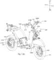
- the power unit 125 is coupled to a rear wheel 130 through the transmission system. Also, the rear wheel 130 is connected to the frame assembly 105 through one or more rear suspension(s) 135.
- a seat assembly 165 is disposed upwardly of the power unit 125 and is supported by the frame assembly 105.
- a storage compartment (not shown) is provided below the seat assembly 165 and is also supported by the frame assembly 105. The utility box is accessible in an open condition of the seat assembly 165.
- the vehicle 100 is provided with plurality of panels 140A, 140B, and 140C that are mounted to the frame assembly 105 and covering the vehicle parts. Especially, a front panel 140A is disposed forward to the head tube 105A.
- the vehicle includes a floorboard 145 disposed at a step-through space ST defined by the frame assembly 105. The user operates the vehicle by resting feet on the floorboard 145, in a seated position.
- a front fender 150 is covering at least a portion of the front wheel 110.
- the front fender 150 is integrated with a front panel 140A of the vehicle 100.
- a rear fender 155 covers at least a portion of the rear wheel 130.
- the vehicle 100 includes a synchronized braking system 200 that is provided with a synchronous brake lever 220 mounted to the handle bar assembly 110 of the vehicle 100 in the present implementation.
- a front wheel brake lever 215 is mounted to the handle bar assembly 110, which functions as an independent brake lever.
- the front wheel brake lever 215 is provided on a right side of the handle bar 100 and the synchronous brake lever 220 is provided on the left side of the handle bar 100.
- a rider may actuate the front brake lever 215 to apply the front wheel brake 205.
- actuation of the synchronous brake lever 220 applies both the front wheel brake 205 and the rear wheel brake 210.
- the disc brake 210 is provided with a disc 210D affixed to the rear wheel 130 and caliper(s) 210C that are functionally coupled to the disc 210D and fixed at a swing arm or the like.
- the caliper is supported by the front suspension 120 in case of the disc brake 205 employed on the front wheel.
- the front brake lever 215 is coupled to a master cylinder 215M, which is connected to the brake caliper(s) of the front wheel brake 205 through a first input hose 225 (shown in Fig. 1 (c) ).
- a master cylinder 215M which is connected to the brake caliper(s) of the front wheel brake 205 through a first input hose 225 (shown in Fig. 1 (c) ).
- pressure is generated in the master cylinder 215M that is transferred to the brake calipers (not shown) of the front wheel brake 205 through the first input hose 225.
- the synchronous brake lever 220 is coupled to another master cylinder 220M, which is connected to a pressure distribution device 300 that is connected to the front brake caliper and the rear brake caliper 210C through a front brake-output hose 240 and a rear brake-output hose 235, respectively.
- the rear brake-output hose is referred to as first output hose 235 and the front brake-output hose 240 is referred to as second output hose 240 for brevity.
- the pressure distribution device 300 is a pressure control device. Hereinafter, the terms 'pressure control device' and the 'pressure distribution device' are interchangeably used. Therefore, operation of the synchronous brake lever 220 generates pressure in the master cylinder 215M that is transferred to the pressure control device 300. From the pressure control device 300, the pressure is distributed to the front wheel brake 205 and the rear wheel brake 210 at a pre-determined ratio. Also, the pressure distribution device 300 is disposed in proximity to the head tube 105A of the vehicle 100. In an implementation, the pressure distribution device 300 is disposed adjacently ahead of the head tube 105A and is secured to the head tube 105A.
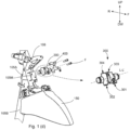
- Fig. 1 (c) depicts an enlarged view of the front portion of the vehicle 100, in accordance with the embodiment depicted in Fig. 1 (b) .
- the pressure distribution device 300 is affixed to the head tube 105A and is positioned at the front facing side of the head tube 105A.
- the pressure distribution device 300 is functionally connected to the front brake lever 215 and the synchronous brake lever 220, which is specifically to a front brake input port 302 and to a synchronous brake input port 301 of the pressure control device 300, respectively.
- the pressure control device 300 includes a front brake output port 303 and a rear brake output 304 (the input port(s) 301, 302 and the output port(s) 303, 304 are depicted in Fig. 1 (d) ).
- Operation of the front brake lever 215 will generate pressure in the master cylinder 215M, which is functionally coupled to the front brake lever 215, is transferred to the front brake input port of the pressure control device 300 through the first input hose 225.
- This pressure is transferred to the front wheel brake 205 through a second output hose 240 thereby actuating the front wheel brake 205.
- the second output hose 240 extends from the pressure control device 300 towards the front wheel brake 205.
- the pressure from the master cylinder 220M is transferred to the pressure control device 300 through a second input hose 230, which is a synchronous brake input hose 230, connected to the pressure control device 300. Then, the pressure from pressure control device 300 is transferred to both the front wheel brake 205 and the rear wheel brake 210 through the second output hose 240 and the first output hose 235 connected to the front brake output and the rear brake output, respectively.
- the first output hose 235 extends rearward from the pressure control device 300 and is supported by at least a portion of the main tube 105B. Further, the first output hose 235 comprises a rigid hose portion 235R that is provided from the main tube 105B towards a floorboard portion 145 of the vehicle 100.
- the pressure control device 300 disposed in the front portion vehicle 100 and in proximity of the head tube 105A provides optimum routing of the hose(s) to the at least one brake lever 215, 220 mounted to the handle bar assembly 110 and to the front wheel brake 205 being substantially equidistant therebetween.
- the front brake system is independent of the synchronous brake system.
- the pressure control device 300 is connected to the front brake lever 215, to the synchronous brake lever 220, the front wheel brake 205, and the rear wheel brake 210 through plurality of flexible hoses 225, 230, 235, 240.
- the handle bar assembly 110 supporting the front brake lever 215 and the rear brake lever 220 is a rotating member and as the pressure control device 300 disposed below the handle bar assembly 110 is rigidly and securely fixed to the frame assembly 105 without adding any weight on the moving/rotating members like the front wheel 115 or the rear wheel 120.
- the position of the pressure control device 300 with reference to the front wheel brake 205 is varying due to the presence of front suspension 120 that compresses and expands with the road conditions.
- the one or more hoses are made of flexible material enable avoidance of damage of hoses.
- the length of the hose is substantially greater that the distance between the points of connection to accommodate the aforementioned variations.
- first input hose 225, the second input hose 230, and the second output hose 240 are provided with lengths with a ratio of maximum length to minimum length being in the range of 0.8 to 1.2 whereby the vehicle 100 with the pressure control device 300 provides optimum hose length.
- the pressure control device 300 is securely mounted to the frame assembly 105 in proximity to the head tube 105A in at least one orientation.
- the pressure control device is disposed in a first orientation with a long axis L-L' thereof is substantially parallel to a lateral direction RH-LH of the vehicle 100.
- the pressure control device 300 includes at least one input port 301, 302 disposed in a downward direction DW to enable smooth curved routing of the input hoses 225, 230 connecting to at least one brake lever 215, 220 to the pressure control device 300.
- the pressure control device 300 includes at least one output port 303, 304 disposed in an upward direction UP to enable optimum routing of the one or more hoses 303, 304 in to at least one of the front wheel brake 205 and the rear wheel brake 210.
- the pressure control device 300 is disposed in a second orientation with the long axis L-L' thereof disposed substantially parallel to the longitudinal direction F-R of the vehicle 100. Therefore, head tube 105A supports an auxiliary power source (not shown) or electrical components like horn or head lamp in the front facing side of head tube 105A and the pressure control device 300 is disposed towards one lateral side RH or LH of the frame assembly 105 and in proximity to the head tube 105A to provide optimum routing of the hose(s).
- the intermediate connector(s) are banjo joint(s) that comprises of a perforated hollow bolt and spherical union for fluid transfer.
- the hose is secured to the at least one of the input(s) and output(s) of the pressure control device 300.
- a poka-yoke bracket 400 is provided that is secured to the pressure control device 300.
- the poka-yoke bracket 400 works in conjunction with banjo joints.
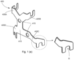
- Fig. 1 (e) depicts an isometric view of the poka-yoke bracket 400, in accordance with the present embodiment.
- Each arm member of the poka-yoke bracket 400 extends towards each of the input ports 301, 302 and each of the output ports 303, 304 of the pressure control device 300.
- each of the arm members 405A, 405B, 405C, 405D is provided with a receiving portion R.
- the receiving portion R is formed by a U-shaped cutout. The arm and the receiving portion are oriented in a specific direction so as to receive an intermediate connector 305A, 305B, 305C, 305D (shown in Fig. 1 (e) ) that are provided with a with a specific orientation.
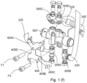
- Fig. 1 (f) depicts an exploded view of the pressure control device 300 assembly, in accordance with the embodiment depicted in Fig. 1 (c) .
- four banjo joints 305A, 305B, 305C, 305D that function as intermediate connectors are secured to ends of the hoses 225, 230, 235, and 240, respectively.
- the pressure control device 300 is provided with a front brake input port 301 and a synchronous brake input port 302 positioned on a downward portion of the pressure control device 300.
- a front brake output port 303 and a rear brake output port 304 are provided in the upward direction/portion UP of the pressure control device 300.
- a first banjo joint 305A connects the synchronous brake lever 220 to the pressure control device 300
- a second banjo joint 305B connects the front brake lever 215 to the pressure control device 300.
- the input ports are provided on opposite sides to the position the brake levers are disposed to provide a smooth and large curvature.
- a third banjo joint 305C and a fourth banjo joint 305D connect the rear wheel brake 210 and the front wheel brake 205 to the pressure control device 300, respectively.
- the banjo joints 305A, 305B, 305C, 305D enable ease of assembly of the connection without affecting the hoses 225, 230, 235 and 240.
- the banjo joints being made of rigid material like metal enables hoses to be retained in a desired orientation.
- the present invention with the pressure control device 300 disposed in proximity to the head tube 105A provides flexibility to change the position of the ports depending on the vehicle layout requirements.
- the arm members 405A, 405B. 405C, and 405D (as shown in Fig. 1 (e) ) of the poka-yoke bracket 400 extend towards the aforementioned port(s), and only one banjo joint of the plurality of banjo joints abuts against the receiving portion(s) R of the banjo joint(s) 305A, 305B, 305C, and 305D. Moreover, this enables use of same pressure control device 300 in a different vehicle layout by merely changing the poka-yoke bracket 400 in accordance to the desired layout. Also, the fasteners F1, F2 securely hold the pressure control device 300 and the poka-yoke bracket 400 to the mounting member 105M.
Landscapes
- Engineering & Computer Science (AREA)
- Mechanical Engineering (AREA)
- Physics & Mathematics (AREA)
- Transportation (AREA)
- Electromagnetism (AREA)
- Fluid Mechanics (AREA)
- Valves And Accessory Devices For Braking Systems (AREA)
- Regulating Braking Force (AREA)
Claims (14)
- Zweirädriges Kraftfahrzeug (100) mit einem synchronisierten Bremssystem (200), wobei das Fahrzeug (100) umfasst:eine Rahmenbaugruppe (105) mit einem Steuerrohr (105 A), das in einem vorderen Abschnitt davon angeordnet ist;eine Vorderradbremse (205), die in der Lage ist, Bremskräfte auf mindestens ein Vorderrad (115) auszuüben, wobei das mindestens eine Vorderrad (115) um das Steuerrohr (105 A) drehbar ist, um das Lenken des Fahrzeugs (100) zu ermöglichen;eine Hinterradbremse (210), die in der Lage ist, Bremskräfte auf mindestens ein Hinterrad (130) auszuüben;eine Drucksteuervorrichtung (300) des synchronisierten Bremssystems (200), die funktionell mit der Hinterradbremse (210) durch einen ersten Ausgangsschlauch (235) verbunden ist und funktionell mit der Vorderradbremse (205) durch einen zweiten Ausgangsschlauch (240) verbunden ist, wobei die Drucksteuervorrichtung (300) in der Lage ist, durch einen Synchronbremshebel (220) betätigt zu werden, wobei die Drucksteuervorrichtung (300) sicher in der Nähe des Kopfrohrs (105A) der Rahmenanordnung (105) angeordnet ist; gekennzeichnet durcheine Ausrichtungshalterung (400), die neben der Drucksteuervorrichtung (300) angeordnet ist und so beschaffen ist, dass sie mit der Drucksteuervorrichtung (300) zusammenwirkt, um eine narrensichere Befestigung eines oder mehrerer Zwischenverbinder (305A, 305B, 305C, 305D) zu ermöglichen, die einen oder mehrere Schläuche (225, 230, 235, 240) mit der Drucksteuervorrichtung (300) verbinden, wobeidie Ausrichtungshalterung (400) ein oder mehrere Armteile (405A, 405B, 405C, 405D) enthält und jedes der ein oder mehreren Armteile (405A, 405B, 405C, 405D) einen Aufnahmeabschnitt (R) enthält, der in der Lage ist, nur einen bestimmten Zwischenverbinder des einen oder der mehreren Zwischenverbinder (305A, 305B, 305C, 305D) aufnehmen kann, wodurch der narrensichere Sitz ermöglicht wird, und das Armelement (405 A, 405B, 405C, 405D) die Zwischenverbinder (405 A, 405B, 405C, 405D) in einer bestimmten Ausrichtung hält, wodurch eine gewünschte Ausrichtung des einen oder der mehreren Schläuche (225, 230, 235, 240) beibehalten wird.
- Zweirädriges Kraftfahrzeug (100) nach Anspruch 1, wobei die Drucksteuervorrichtung (300) im Wesentlichen gleich weit von mindestens einem Bremshebel (215, 220), der an einer um das Steuerrohr (105A) drehbaren Lenkstangenanordnung (110) angebracht ist, und von der Vorderradbremse (205) entfernt ist.
- Zweirädriges Kraftfahrzeug (100) nach Anspruch 1, wobei die Drucksteuervorrichtung (300) sicher vor dem Steuerrohr (105 A) angeordnet ist und die Drucksteuervorrichtung (300) eine lange Achse (L-L') aufweist, die im Wesentlichen in einer ersten Ausrichtung parallel zu einer seitlichen Richtung (RH-LH) des Kraftfahrzeugs (100) angeordnet ist.
- Zweirädriges Kraftfahrzeug (100) nach Anspruch 1, wobei die Drucksteuervorrichtung (300) sicher in Richtung einer Seite (RH, LH) des Kopfrohrs (105A) angeordnet ist und die Drucksteuervorrichtung (300) eine lange Achse (L-LD) aufweist, die in einer zweiten Ausrichtung parallel zu einer Längsrichtung (F-R) des Kraftfahrzeugs (100) angeordnet ist.
- Zweirädriges Kraftfahrzeug (100) nach Anspruch 1, 3 oder 4, wobei die Drucksteuervorrichtung (300) fest an der Rahmenanordnung (105) in der Nähe des Steuerrohrs (105A) in mindestens einer der ersten Ausrichtung oder der zweiten Ausrichtung angebracht ist und die Drucksteuervorrichtung (300) mindestens einen Eingangsanschluss (301, 302) aufweist, der in einer Abwärtsrichtung (DW) angeordnet ist, um eine gekrümmte Führung eines oder mehrerer Eingangsschläuche (225, 230) zu ermöglichen, die den mindestens einen Bremshebel (215, 220) damit verbinden, und die Drucksteuervorrichtung (300) mindestens einen Ausgangsanschluss (303, 304) aufweist, der in einer Aufwärtsrichtung (UP) angeordnet ist, um eine Führung des einen oder der mehreren Ausgangsschläuche (235, 240) zu mindestens einer der Vorderradbremse (205) und der Hinterradbremse (210) zu ermöglichen.
- Zweirädriges Kraftfahrzeug (100) nach Anspruch 1, 3 oder 4, wobei die Drucksteuervorrichtung (300) fest an der Rahmenanordnung (105) in der Nähe des Steuerrohrs (105A) in mindestens einer der ersten Ausrichtung und der zweiten Ausrichtung angebracht ist und die Drucksteuervorrichtung (300) mindestens einen Eingangsanschluss (301, 302) aufweist, der in einer Abwärtsrichtung (DW) angeordnet ist, und mindestens einen Ausgangsanschluss (303, 304) aufweist, der in einer Aufwärtsrichtung (UP) angeordnet ist.
- Zweirädriges Kraftfahrzeug (100) nach Anspruch 1 oder 3, wobei die Drucksteuervorrichtung (300) an einer der Vorderseite zugewandten Seite des Steuerrohrs (105 A) angebracht und unterhalb der Lenkstangenbaugruppe (110) und oberhalb der Vorderradbremse (120) dazwischen angeordnet ist, wodurch die Drucksteuervorrichtung (300) im Wesentlichen in gleichem Abstand zu dem Synchronbremshebel (220), der an der Lenkstangenbaugruppe (110) angebracht ist, und zu der Vorderradbremse (205) liegt.
- Zweirädriges Kraftfahrzeug (100) nach Anspruch 1, wobei die Drucksteuerungsvorrichtung (300) an einem Montageelement (105M) befestigt ist, das an der Rahmenanordnung (105) befestigt ist, wobei das Montageelement (105M) ein U-förmiges Profil mit Spiel aufweist, um die Befestigung der Drucksteuerungsvorrichtung (300) zu ermöglichen, und wobei das Montageelement (105M) einen oder mehrere Montagepunkte aufweist, die vorgesehen sind, um sich mit einem oder mehreren Montagepunkten auszurichten, die an der Drucksteuerungsvorrichtung (300) vorgesehen sind, wodurch die Montage der Drucksteuerungsvorrichtung (300) in einer gewünschten Ausrichtung ermöglicht wird.
- Zweirädriges Kraftfahrzeug (100) nach Anspruch 1, wobei die Drucksteuerungsvorrichtung (300) im Wesentlichen entlang einer seitlichen Mitte des Fahrzeugs (100) angeordnet ist, wodurch ein Schwerpunkt der Drucksteuerungsvorrichtung (300) und ein Schwerpunkt des Fahrzeugs (100) in einer Linie liegen und ein Gleichgewicht in einer seitlichen Richtung (RH-LH) bereitstellen.
- Zweirädriges Kraftfahrzeug (100) nach Anspruch 1, wobei die Drucksteuereinrichtung (300) seitlich versetzt von einem seitlichen Mittelpunkt des Fahrzeugs (100) angeordnet ist, wodurch die Drucksteuereinrichtung (300) einen Schwerpunkt des Fahrzeugs (100) ausgleicht.
- Zweirädriges Kraftfahrzeug (100) nach Anspruch 1, wobei die Drucksteuervorrichtung (300) mit einem Bremshebel (220) und dem anderen Bremshebel (215) über einen ersten Eingangsschlauch (225) bzw. einen zweiten Eingangsschlauch (230) verbunden ist und die Drucksteuervorrichtung (300) mit der Vorderradbremse (205) über einen zweiten Schlauch (240) verbunden ist, und wobei das Verhältnis der maximalen Länge zur minimalen Länge zwischen dem ersten Eingangsschlauch (255), dem zweiten Eingangsschlauch (230) und dem zweiten Ausgangsschlauch (240) im Bereich von 0. 8 bis 1,2 liegt.
- Zweirädriges Kraftfahrzeug (100) nach Anspruch 1, wobei die Drucksteuervorrichtung (300) hinter einer Frontplatte (140A) und oberhalb eines vorderen Kotflügels (150) angeordnet ist, die Frontplatte (140A) zumindest einen Teil der Drucksteuervorrichtung (300) abdeckt und die Frontplatte (140A) von einer zusätzlichen Halterung (106) getragen wird, die an dem Steuerrohr (105A) angebracht ist, das sich in Vorwärtsrichtung (F) über einen vordersten Abschnitt der Drucksteuervorrichtung (300) hinaus erstreckt.
- Zweirädriges Fahrzeug (100) nach Anspruch 1, wobei die Drucksteuervorrichtung (300) mit einem vorderen Bremshebel (215) verbunden ist, um die Bremskraft unabhängig von der Vorderradbremse (205) aufzubringen, und der vordere Bremshebel (215) an der Lenkstangenanordnung (110) des Fahrzeugs (100) angebracht ist.
- Ausrichtungshalterung (400), die dazu geeignet ist, mit einer Drucksteuervorrichtung (300) eines synchronisierten Bremssystems (200) für ein zweirädriges Kraftfahrzeug (100) nach einem der Ansprüche 1 bis 13 zusammenzuwirken, wobei die Ausrichtungshalterung (400) umfasst:- einen Basisabschnitt (410); und- ein oder mehrere Armelemente (405A, 405B, 405C, 405D), die von dem Basisabschnitt (410) getragen werden,wobei
das eine oder die mehreren Armelement(e) (405A, 405B, 405C, 405D) so konfiguriert ist/sind, dass es/sie sich in Richtung eines oder mehrerer Eingangsanschlusses/anschlüsse (301, 302) und in Richtung eines oder mehrerer Ausgangsanschlusses/anschlüsse (303, 304) der Drucksteuerungsvorrichtung (300) erstreckt/erstrecken, und jedes des einen oder der mehreren Armelemente (405A, 405B, 405C, 405D) einen Aufnahmeabschnitt (R) aufweist, der in der Lage ist, nur einen oder mehrere spezifische Zwischenverbinder (305A, 305B, 305C, 305D) aufzunehmen, die einen oder mehrere Schläuche (224, 230, 235, 240) mit der Drucksteuervorrichtung (300) verbinden.
Applications Claiming Priority (2)
| Application Number | Priority Date | Filing Date | Title |
|---|---|---|---|
| IN201641040199 | 2016-11-24 | ||
| PCT/IB2017/057378 WO2018096493A1 (en) | 2016-11-24 | 2017-11-24 | A two-wheeled vehicle with synchronized braking system |
Publications (4)
| Publication Number | Publication Date |
|---|---|
| EP3544883A1 EP3544883A1 (de) | 2019-10-02 |
| EP3544883A4 EP3544883A4 (de) | 2020-11-25 |
| EP3544883B1 true EP3544883B1 (de) | 2025-04-16 |
| EP3544883C0 EP3544883C0 (de) | 2025-04-16 |
Family
ID=62195780
Family Applications (1)
| Application Number | Title | Priority Date | Filing Date |
|---|---|---|---|
| EP17874792.9A Active EP3544883B1 (de) | 2016-11-24 | 2017-11-24 | Zweirädriges fahrzeug mit synchronisiertem bremssystem |
Country Status (3)
| Country | Link |
|---|---|
| EP (1) | EP3544883B1 (de) |
| CN (1) | CN110035948B (de) |
| WO (1) | WO2018096493A1 (de) |
Families Citing this family (2)
| Publication number | Priority date | Publication date | Assignee | Title |
|---|---|---|---|---|
| BR112021009671A2 (pt) | 2018-11-19 | 2021-08-24 | Tvs Motor Company Limited | Um veículo motorizado e um membro de sustentação para uma unidade de freio do mesmo |
| EP4100303B1 (de) * | 2020-02-04 | 2024-02-28 | Indian Motorcycle International, LLC | Motorrad |
Family Cites Families (8)
| Publication number | Priority date | Publication date | Assignee | Title |
|---|---|---|---|---|
| JP2003261086A (ja) * | 2002-03-07 | 2003-09-16 | Shimano Inc | 自転車用ブレーキ操作装置 |
| JPWO2009050961A1 (ja) * | 2007-10-18 | 2011-02-24 | ボッシュ株式会社 | ブレーキ液圧制御装置 |
| CN201124920Y (zh) * | 2007-11-21 | 2008-10-01 | 南京金城机械有限公司 | 摩托车的液压联合制动系统 |
| JP5227872B2 (ja) * | 2008-08-29 | 2013-07-03 | 本田技研工業株式会社 | 車両用連動ブレーキ装置 |
| JP5627112B2 (ja) * | 2011-07-01 | 2014-11-19 | 本田技研工業株式会社 | 自動二輪車 |
| JP5751989B2 (ja) | 2011-08-27 | 2015-07-22 | 本田技研工業株式会社 | 自動二輪車 |
| TW201313541A (zh) * | 2011-09-23 | 2013-04-01 | Well Child Technology Co | 安全煞車裝置 |
| WO2016113756A1 (en) * | 2015-01-14 | 2016-07-21 | Tvs Motor Company Limited | Synchronized braking system for two-wheeled vehicles |
-
2017
- 2017-11-24 EP EP17874792.9A patent/EP3544883B1/de active Active
- 2017-11-24 WO PCT/IB2017/057378 patent/WO2018096493A1/en not_active Ceased
- 2017-11-24 CN CN201780072452.2A patent/CN110035948B/zh active Active
Also Published As
| Publication number | Publication date |
|---|---|
| EP3544883A1 (de) | 2019-10-02 |
| CN110035948B (zh) | 2021-07-06 |
| EP3544883A4 (de) | 2020-11-25 |
| WO2018096493A1 (en) | 2018-05-31 |
| EP3544883C0 (de) | 2025-04-16 |
| BR112019010529A2 (pt) | 2019-09-17 |
| CN110035948A (zh) | 2019-07-19 |
Similar Documents
| Publication | Publication Date | Title |
|---|---|---|
| US6450301B1 (en) | Brake device | |
| US8651213B2 (en) | Brake device for saddled vehicle | |
| CN105722753B (zh) | 摩托车 | |
| JP5627112B2 (ja) | 自動二輪車 | |
| JP5871382B2 (ja) | 鞍乗型車両のハーネス配策構造 | |
| EP0995653A2 (de) | Bremsvorrichtung für Fahrzeug mit Rohrlenker | |
| WO2018104833A1 (en) | Synchronized braking system | |
| EP3544883B1 (de) | Zweirädriges fahrzeug mit synchronisiertem bremssystem | |
| US7621566B2 (en) | Brake hose support structure | |
| EP3715234B1 (de) | Sattelfahrzeug | |
| WO2018154428A1 (en) | Foot operated synchronized braking system | |
| JP6904999B2 (ja) | 鞍乗り型車両 | |
| JP2018177201A (ja) | 鞍乗型車両 | |
| JP2019098864A (ja) | 鞍乗型車両のブレーキ配管構造 | |
| EP3388322B1 (de) | Grätschsitzfahrzeug | |
| JP2019081518A (ja) | 鞍乗り型車両 | |
| WO2018109705A1 (en) | Synchronous brake actuation assembly for a two-wheeler | |
| EP4180309A1 (de) | Sattelfahrzeug | |
| US20200255083A1 (en) | Brake piping structure for saddled vehicles | |
| BR112019010529B1 (pt) | Veículo de duas rodas com sistema de frenagem sincronizado | |
| JP2018140761A (ja) | 鞍乗型車両 | |
| WO2020194335A1 (en) | A synchronized braking system for a vehicle | |
| WO2020202198A1 (en) | Multi-purpose swing arm of vehicle | |
| WO2020115770A1 (en) | Speed deceleration system | |
| WO2020255170A1 (en) | Speed deceleration system of vehicle |
Legal Events
| Date | Code | Title | Description |
|---|---|---|---|
| STAA | Information on the status of an ep patent application or granted ep patent |
Free format text: STATUS: THE INTERNATIONAL PUBLICATION HAS BEEN MADE |
|
| PUAI | Public reference made under article 153(3) epc to a published international application that has entered the european phase |
Free format text: ORIGINAL CODE: 0009012 |
|
| STAA | Information on the status of an ep patent application or granted ep patent |
Free format text: STATUS: REQUEST FOR EXAMINATION WAS MADE |
|
| 17P | Request for examination filed |
Effective date: 20190514 |
|
| AK | Designated contracting states |
Kind code of ref document: A1 Designated state(s): AL AT BE BG CH CY CZ DE DK EE ES FI FR GB GR HR HU IE IS IT LI LT LU LV MC MK MT NL NO PL PT RO RS SE SI SK SM TR |
|
| AX | Request for extension of the european patent |
Extension state: BA ME |
|
| DAV | Request for validation of the european patent (deleted) | ||
| DAX | Request for extension of the european patent (deleted) | ||
| A4 | Supplementary search report drawn up and despatched |
Effective date: 20201023 |
|
| RIC1 | Information provided on ipc code assigned before grant |
Ipc: F16L 27/093 20060101ALI20201019BHEP Ipc: B60T 1/08 20060101ALI20201019BHEP Ipc: B60T 8/26 20060101ALI20201019BHEP Ipc: B62L 3/02 20060101ALI20201019BHEP Ipc: B62L 3/08 20060101AFI20201019BHEP Ipc: F16L 41/04 20060101ALI20201019BHEP |
|
| STAA | Information on the status of an ep patent application or granted ep patent |
Free format text: STATUS: EXAMINATION IS IN PROGRESS |
|
| 17Q | First examination report despatched |
Effective date: 20221021 |
|
| GRAP | Despatch of communication of intention to grant a patent |
Free format text: ORIGINAL CODE: EPIDOSNIGR1 |
|
| STAA | Information on the status of an ep patent application or granted ep patent |
Free format text: STATUS: GRANT OF PATENT IS INTENDED |
|
| INTG | Intention to grant announced |
Effective date: 20241108 |
|
| GRAS | Grant fee paid |
Free format text: ORIGINAL CODE: EPIDOSNIGR3 |
|
| GRAA | (expected) grant |
Free format text: ORIGINAL CODE: 0009210 |
|
| STAA | Information on the status of an ep patent application or granted ep patent |
Free format text: STATUS: THE PATENT HAS BEEN GRANTED |
|
| AK | Designated contracting states |
Kind code of ref document: B1 Designated state(s): AL AT BE BG CH CY CZ DE DK EE ES FI FR GB GR HR HU IE IS IT LI LT LU LV MC MK MT NL NO PL PT RO RS SE SI SK SM TR |
|
| REG | Reference to a national code |
Ref country code: GB Ref legal event code: FG4D |
|
| REG | Reference to a national code |
Ref country code: CH Ref legal event code: EP |
|
| REG | Reference to a national code |
Ref country code: IE Ref legal event code: FG4D |
|
| REG | Reference to a national code |
Ref country code: DE Ref legal event code: R096 Ref document number: 602017088993 Country of ref document: DE |
|
| U01 | Request for unitary effect filed |
Effective date: 20250514 |
|
| U07 | Unitary effect registered |
Designated state(s): AT BE BG DE DK EE FI FR IT LT LU LV MT NL PT RO SE SI Effective date: 20250520 |
|
| PG25 | Lapsed in a contracting state [announced via postgrant information from national office to epo] |
Ref country code: ES Free format text: LAPSE BECAUSE OF FAILURE TO SUBMIT A TRANSLATION OF THE DESCRIPTION OR TO PAY THE FEE WITHIN THE PRESCRIBED TIME-LIMIT Effective date: 20250416 |
|
| PG25 | Lapsed in a contracting state [announced via postgrant information from national office to epo] |
Ref country code: NO Free format text: LAPSE BECAUSE OF FAILURE TO SUBMIT A TRANSLATION OF THE DESCRIPTION OR TO PAY THE FEE WITHIN THE PRESCRIBED TIME-LIMIT Effective date: 20250716 Ref country code: GR Free format text: LAPSE BECAUSE OF FAILURE TO SUBMIT A TRANSLATION OF THE DESCRIPTION OR TO PAY THE FEE WITHIN THE PRESCRIBED TIME-LIMIT Effective date: 20250717 |
|
| PG25 | Lapsed in a contracting state [announced via postgrant information from national office to epo] |
Ref country code: PL Free format text: LAPSE BECAUSE OF FAILURE TO SUBMIT A TRANSLATION OF THE DESCRIPTION OR TO PAY THE FEE WITHIN THE PRESCRIBED TIME-LIMIT Effective date: 20250416 |
|
| PG25 | Lapsed in a contracting state [announced via postgrant information from national office to epo] |
Ref country code: HR Free format text: LAPSE BECAUSE OF FAILURE TO SUBMIT A TRANSLATION OF THE DESCRIPTION OR TO PAY THE FEE WITHIN THE PRESCRIBED TIME-LIMIT Effective date: 20250416 |
|
| PG25 | Lapsed in a contracting state [announced via postgrant information from national office to epo] |
Ref country code: RS Free format text: LAPSE BECAUSE OF FAILURE TO SUBMIT A TRANSLATION OF THE DESCRIPTION OR TO PAY THE FEE WITHIN THE PRESCRIBED TIME-LIMIT Effective date: 20250716 |
|
| PG25 | Lapsed in a contracting state [announced via postgrant information from national office to epo] |
Ref country code: IS Free format text: LAPSE BECAUSE OF FAILURE TO SUBMIT A TRANSLATION OF THE DESCRIPTION OR TO PAY THE FEE WITHIN THE PRESCRIBED TIME-LIMIT Effective date: 20250816 |
|
| U20 | Renewal fee for the european patent with unitary effect paid |
Year of fee payment: 9 Effective date: 20251128 |
|
| PG25 | Lapsed in a contracting state [announced via postgrant information from national office to epo] |
Ref country code: SM Free format text: LAPSE BECAUSE OF FAILURE TO SUBMIT A TRANSLATION OF THE DESCRIPTION OR TO PAY THE FEE WITHIN THE PRESCRIBED TIME-LIMIT Effective date: 20250416 |
|
| PG25 | Lapsed in a contracting state [announced via postgrant information from national office to epo] |
Ref country code: CZ Free format text: LAPSE BECAUSE OF FAILURE TO SUBMIT A TRANSLATION OF THE DESCRIPTION OR TO PAY THE FEE WITHIN THE PRESCRIBED TIME-LIMIT Effective date: 20250416 |
|
| PG25 | Lapsed in a contracting state [announced via postgrant information from national office to epo] |
Ref country code: SK Free format text: LAPSE BECAUSE OF FAILURE TO SUBMIT A TRANSLATION OF THE DESCRIPTION OR TO PAY THE FEE WITHIN THE PRESCRIBED TIME-LIMIT Effective date: 20250416 |