EP3543437A1 - Schlossanordnung mit einem schloss für eine gangflügeltür und einem gegenschloss für eine standflügeltür - Google Patents
Schlossanordnung mit einem schloss für eine gangflügeltür und einem gegenschloss für eine standflügeltür Download PDFInfo
- Publication number
- EP3543437A1 EP3543437A1 EP18163472.6A EP18163472A EP3543437A1 EP 3543437 A1 EP3543437 A1 EP 3543437A1 EP 18163472 A EP18163472 A EP 18163472A EP 3543437 A1 EP3543437 A1 EP 3543437A1
- Authority
- EP
- European Patent Office
- Prior art keywords
- lock
- latch
- locking element
- locking
- actuator
- Prior art date
- Legal status (The legal status is an assumption and is not a legal conclusion. Google has not performed a legal analysis and makes no representation as to the accuracy of the status listed.)
- Granted
Links
Images






Classifications
-
- E—FIXED CONSTRUCTIONS
- E05—LOCKS; KEYS; WINDOW OR DOOR FITTINGS; SAFES
- E05C—BOLTS OR FASTENING DEVICES FOR WINGS, SPECIALLY FOR DOORS OR WINDOWS
- E05C7/00—Fastening devices specially adapted for two wings
- E05C7/04—Fastening devices specially adapted for two wings for wings which abut when closed
- E05C7/06—Fastening devices specially adapted for two wings for wings which abut when closed a fastening device for one wing being actuated or controlled by closing another wing
-
- E—FIXED CONSTRUCTIONS
- E05—LOCKS; KEYS; WINDOW OR DOOR FITTINGS; SAFES
- E05B—LOCKS; ACCESSORIES THEREFOR; HANDCUFFS
- E05B17/00—Accessories in connection with locks
- E05B17/22—Means for operating or controlling lock or fastening device accessories, i.e. other than the fastening members, e.g. switches, indicators
-
- E—FIXED CONSTRUCTIONS
- E05—LOCKS; KEYS; WINDOW OR DOOR FITTINGS; SAFES
- E05B—LOCKS; ACCESSORIES THEREFOR; HANDCUFFS
- E05B47/00—Operating or controlling locks or other fastening devices by electric or magnetic means
- E05B47/0001—Operating or controlling locks or other fastening devices by electric or magnetic means with electric actuators; Constructional features thereof
- E05B47/0012—Operating or controlling locks or other fastening devices by electric or magnetic means with electric actuators; Constructional features thereof with rotary electromotors
-
- E—FIXED CONSTRUCTIONS
- E05—LOCKS; KEYS; WINDOW OR DOOR FITTINGS; SAFES
- E05B—LOCKS; ACCESSORIES THEREFOR; HANDCUFFS
- E05B63/00—Locks or fastenings with special structural characteristics
- E05B63/18—Locks or fastenings with special structural characteristics with arrangements independent of the locking mechanism for retaining the bolt or latch in the retracted position
- E05B63/20—Locks or fastenings with special structural characteristics with arrangements independent of the locking mechanism for retaining the bolt or latch in the retracted position released automatically when the wing is closed
-
- E—FIXED CONSTRUCTIONS
- E05—LOCKS; KEYS; WINDOW OR DOOR FITTINGS; SAFES
- E05B—LOCKS; ACCESSORIES THEREFOR; HANDCUFFS
- E05B65/00—Locks or fastenings for special use
- E05B65/10—Locks or fastenings for special use for panic or emergency doors
- E05B65/1006—Locks or fastenings for special use for panic or emergency doors of the vertical rod type
- E05B65/1013—Trigger means for holding the bolt in the retracted position and releasing the bolt when the door is closed
-
- E—FIXED CONSTRUCTIONS
- E05—LOCKS; KEYS; WINDOW OR DOOR FITTINGS; SAFES
- E05B—LOCKS; ACCESSORIES THEREFOR; HANDCUFFS
- E05B15/00—Other details of locks; Parts for engagement by bolts of fastening devices
- E05B15/04—Spring arrangements in locks
- E05B2015/0403—Wound springs
-
- E—FIXED CONSTRUCTIONS
- E05—LOCKS; KEYS; WINDOW OR DOOR FITTINGS; SAFES
- E05B—LOCKS; ACCESSORIES THEREFOR; HANDCUFFS
- E05B15/00—Other details of locks; Parts for engagement by bolts of fastening devices
- E05B15/04—Spring arrangements in locks
- E05B2015/0458—Leaf springs; Non-wound wire springs
-
- E—FIXED CONSTRUCTIONS
- E05—LOCKS; KEYS; WINDOW OR DOOR FITTINGS; SAFES
- E05B—LOCKS; ACCESSORIES THEREFOR; HANDCUFFS
- E05B45/00—Alarm locks
- E05B45/06—Electric alarm locks
- E05B2045/065—Switch or sensor type used in alarm locks
-
- E—FIXED CONSTRUCTIONS
- E05—LOCKS; KEYS; WINDOW OR DOOR FITTINGS; SAFES
- E05B—LOCKS; ACCESSORIES THEREFOR; HANDCUFFS
- E05B47/00—Operating or controlling locks or other fastening devices by electric or magnetic means
- E05B47/0001—Operating or controlling locks or other fastening devices by electric or magnetic means with electric actuators; Constructional features thereof
- E05B2047/0014—Constructional features of actuators or power transmissions therefor
- E05B2047/0015—Output elements of actuators
- E05B2047/0016—Output elements of actuators with linearly reciprocating motion
-
- E—FIXED CONSTRUCTIONS
- E05—LOCKS; KEYS; WINDOW OR DOOR FITTINGS; SAFES
- E05B—LOCKS; ACCESSORIES THEREFOR; HANDCUFFS
- E05B47/00—Operating or controlling locks or other fastening devices by electric or magnetic means
- E05B47/0001—Operating or controlling locks or other fastening devices by electric or magnetic means with electric actuators; Constructional features thereof
- E05B2047/0014—Constructional features of actuators or power transmissions therefor
- E05B2047/0018—Details of actuator transmissions
- E05B2047/0024—Cams
-
- E—FIXED CONSTRUCTIONS
- E05—LOCKS; KEYS; WINDOW OR DOOR FITTINGS; SAFES
- E05B—LOCKS; ACCESSORIES THEREFOR; HANDCUFFS
- E05B47/00—Operating or controlling locks or other fastening devices by electric or magnetic means
- E05B2047/0048—Circuits, feeding, monitoring
- E05B2047/0067—Monitoring
-
- E—FIXED CONSTRUCTIONS
- E05—LOCKS; KEYS; WINDOW OR DOOR FITTINGS; SAFES
- E05B—LOCKS; ACCESSORIES THEREFOR; HANDCUFFS
- E05B47/00—Operating or controlling locks or other fastening devices by electric or magnetic means
- E05B47/02—Movement of the bolt by electromagnetic means; Adaptation of locks, latches, or parts thereof, for movement of the bolt by electromagnetic means
- E05B47/026—Movement of the bolt by electromagnetic means; Adaptation of locks, latches, or parts thereof, for movement of the bolt by electromagnetic means the bolt moving rectilinearly
Definitions
- the present invention relates to a lock assembly according to the closer defined in the preamble of claim 1.
- a disadvantage of the known solutions for such lock arrangements is that, in the event of an opening operation of the door, the control-trap mechanism may not reliably enable unlocking.
- the control-trap mechanism may not reliably enable unlocking.
- a transfer of the locking element into the locking position is problematic, as this blocks a renewed closing of the door.
- a renewed transfer into the locking position would be z. B. possible if the tax trap occupies a retracted position too long during an opening operation.
- the lock comprises at least one locking element, wherein the locking element engages in a locking position of the locking element in an opening of the counter-lock.
- the locking element is disengaged from the opening of the counter-lock and / or is arranged outside a counter-lock housing.
- the lock comprises at least one control latch, wherein the control latch occupies a retracted position for movement of the locking element in the locking position, wherein in a protruding position of the control latch, the movement of the locking element is prevented in the locking position.
- the protruding position serves to detect an open gangway door
- the retracted position serves to detect a closed state of the door.
- the counter lock includes a latch member actuator, wherein the latch member actuator is movable from a retracted position to an operative position.
- the counter lock comprises a strike plate for holding the control catch in the retracted position. The striking plate can thus cause the retracted position of the control latch in the closed state of the door.
- the locking element actuator is designed to hold the locking element in the unlocked position in the active position until the control latch, in particular during an opening operation of the door, has reached the projecting position.
- the locking element actuator in the operative position holds the locking element in the unlocked position until the control catch has reached the projecting position by increasing the distance between the lock and the counter lock.
- a control latch opening in a lock housing of the lock through which the control latch from the retracted position in the protruding position is movable to move away from the lock plate of the counter-lock, whereby the control latch can move from the retracted position to the projecting position.
- the control latch can be supported on the striking plate, in particular slide along the striking plate.
- the strike plate can be closed, in particular flat, in the region in which the control catch can be supported on the strike plate, be formed.
- the solution according to the invention has the advantage that reliable opening and re-closing of the door is made possible because unwanted movement of the locking element from the unlocking position to the locking position when the door is open can be prevented. Because the latch actuator reliably holds the locking element in the unlocked position until the control catch has reached the projecting position, it can be ensured that first the control latch assumes the position in which the locking element remains in the unlocked position before the locking element actuator ceases to engage the locking element to hold in the unlocked position. Thus, in particular, an interaction between the locking element actuator and the locking element is only canceled if the locking element remains in the unlocked position without the locking element actuator.
- the latch member actuator is thus adapted to hold in the operative position, the locking element in the unlocked position until the control latch has reached the projecting position, wherein the control latch reaches the projecting position by the lock, in particular the control latch opening of the lock, away from the strike plate ,
- the lock may comprise a lock mechanism element, in particular a lock slide, by means of which the lock element is held in the unlocked position.
- the control catch prevents in the protruding position that the lock mechanism element is movable such that the locking element is movable into the locking position.
- the lock mechanism element can in particular be operatively connected to the locking element such that a movement of the lock mechanism element from a first position to a second position causes the locking element to move from the unlocked position into the locking position. Additionally or alternatively, the movement of the lock mechanism element from the second position into the first position can bring about a movement of the locking element from the locking position into the unlocked position.
- the control catch may, in the projecting position, cause the lock mechanism element to remain in the first position.
- the locking element and the lock mechanism element can, for. B. interact with each other via a backdrop.
- the locking element may be designed as a bolt, as a trap or as a latch bolt.
- An actuator of the buckle may be utilized to open and / or unlock the door, the wing door, and / or the wing door, which actuator may also cause movement of the latch member actuator from the retracted position to the operative position.
- control latch opening can be removed from the strike plate by an opening movement of the floor and / or the wing door.
- the removal of the control latch opening from the strike plate is effected in particular by the increasing distance between the lock and the strike plate. This may be the case in particular if both the At the same time, perform an opening movement of the wing door and the wing door.
- a simultaneous opening movement can take place, if it is a rebated door and the door is opened via the wing door.
- the control latch can rest on reaching the projecting position on the strike plate.
- the lock can thus be designed as a self-locking lock.
- the locking element can always be extended into the locking position when the lock is opposite the counter lock.
- the lock can be designed in particular as an anti-panic lock.
- the lock can be unlocked mechanically by the operation of a panic bar or a door handle.
- the panic bar and / or the door handle can be connectable to the lock, in particular to an actuating element of the lock.
- the counter lock can be designed in particular as a self-locking counter lock.
- at least one locking bar can always be moved from a retracted position to an extended position when the locking bar is opposite a closing element for the locking bar.
- the locking bar can be connected to the counter lock.
- the counter lock can be designed in particular as an anti-panic counter lock.
- the latch-element actuator can move from the retracted position into the operative position.
- the latch bar upon actuation of a panic bar or door handle, the latch bar may be movable from the extended position to the retracted position.
- the panic bar and / or the door handle can be connected to the counter lock, in particular with an actuating element of the counter lock.
- the movement of the locking element takes place in the locking position by a spring of the lock and / or supported.
- This optionally enables a mechanism in which the latch member changes from the unlocked position to the latched position when the control latch is in the retracted position and the latch member actuator is in the retracted position.
- the locking element actuator is in particular movable from the retracted position to the operative position and vice versa.
- the latch member actuator allows movement of the latch member to the latched position.
- the locking element actuator prevents the locking element from assuming the locking position.
- the operative position of the locking element actuator holds the locking element in the unlocked position. If the locking element is transferred from the locking position into the unlocked position by means of the counter lock, in particular the locking element actuator moves from the retracted position into the operative position.
- the locking element actuator may bear resiliently against the locking element in the operative position.
- the locking element actuator can be designed in several parts, wherein preferably the locking element actuator comprises an engagement element and an active element.
- the engagement element is preferred. In the active position, the active element bears against the locking element.
- the engagement element and the active element may be resiliently connected to each other. As a result, it is possible to flexibly compensate for a position for abutment on or a distance from the locking element.
- This has the advantage that the mechanism particularly reliable move over a movement of the locking element actuator, the locking element from the counter lock housing and can hold in the unlocked position, until the tax trap the projecting Reached position.
- the spring between the active element and the engagement element has to compensate for an ever-increasing gap between the lock and the strike plate.
- the locking element actuator is translationally movable.
- the active element may be formed as an actuating pin, wherein in particular a spring of the locking element actuator is designed as a spiral spring.
- the actuating pin can be designed for deblocking the locking element. It is conceivable that the locking element is blocked in the locking position.
- a blocking element can be provided in the lock.
- the active element can perform the deblocking, z. B. by the active element presses on a Deblockadeelement of the locking element.
- the spring force of the spring can support the deblocking.
- the active element is guided in the engagement element, in particular when the locking element actuator is translationally movable.
- the width of an end face of the active element may be greater than a width of the active element in the interior of the engaging element.
- both a guide of the active element and a high width, with which the active element rests against the locking element achieved. Due to the high width with which the locking element actuator rests on the locking element, it is achieved that even with an increasing distance of the lock and the counter-lock the locking element actuator holds the locking element in the unlocked position.
- the geometric design and extent of the active element, so in particular the width of the end face be adapted to the locking element.
- the active element and the engagement element may comprise mutually corresponding stop surfaces, wherein by the stop surfaces, a movement of the Active element is limited from the attack element.
- the limitation of the movement serves in particular to ensure a reliable function, since the movement of the active element and possibly also a protruding of the active element from the engagement element and / or from the counter lock housing in the operative position to the arrangement of the counter lock with respect to the lock, in particular in the partially open state of the door, and / or must be adapted to the formation of the locking element.
- the locking element actuator with the engagement element and the active element is pivotable about a first axis.
- the active element can be mounted pivotably about a second axis on the engagement element, wherein in particular the spring is designed as a leaf spring.
- the spring is mounted between the active element and the engagement element. This allows a particularly space-saving design of the locking element actuator.
- the engagement element has a backdrop over which the attack element can be pivoted. In the backdrop can attack a connected to the actuator of the counter lock counter lock mechanism part. A movement of the counter lock mechanism part in the backdrop to the movement of the attack element cause.
- control catch comprises a control case head, which is rotatably mounted and / or provided with a tip. It is also advantageous if the control case head is mounted such that the rotation facilitates movement of the control latch in the projecting position position. This simplifies the provision of the functionality of the tax trap to stand out when opening the door and thus, for example, to prevent a transfer of the locking element in the locked position in the at least partially open state of the door.
- a Abraganteil of the locking element actuator which protrudes in the operative position of the strike plate, at least 45% of a Abraganteils the tax trap with which the tax trap protrudes in the projecting position of the lock is, preferably, that the Abraganteil of Riegelelementbetuschigers at least 50% of Abraganteils the tax trap, particularly preferred that the Abraganteil the Riegelelementbet2011igers at least 55% of Abraganteils the tax trap is.
- the Abgraganteil of Riegelelementbet2011igers z. B. amount to 100% of Abraganteils the tax trap. This has the advantage that the locking element is reliably held during the opening process in the unlocked position.
- the Abraganteil of the locking element actuator to the square and / or the width of the striking plate or the counter lock to the square approximately equal to the Abraganteil the tax trap square.
- “about” is meant an area +/- 20%, preferably +/- 10%.
- the width of an end face of the locking element actuator and the width of an end face of the locking element to be designed in such a way that at least one edge of the end face of the locking element actuator, which is in particular facing the inside of the fixed door, and an edge of the end face of the locking element, preferably facing the outside of the gangway door, abut each other when the control latch is in the projecting position.
- the end face of the locking element actuator is at least 80% of the width of the counter lock of the striker plate.
- a spring of the locking element actuator in particular the spring force of the spring, is designed such that the locking element actuator always resiliently abuts the locking element during the movement of the locking element in the unlocking position, in particular that the locking element actuator then resiliently bears against the locking element when the unlocking operation is performed against a preload (preferably on the latch member). It is advantageously provided that the locking element corresponds to a latch of the castle.
- the spring can be designed such that a pushing out of the locking element from the counter lock housing is possible even with a preload.
- the lock may also be possible for the lock to include a trap.
- the latch may be movable to a locking position and an unlocking position.
- the latch can be moved into the unlocked position when in contact with an edge of a latch opening of the counter lock or against a strike plate of the counter lock and / or locked in the unlocked state, in particular in a blocked state and in an unblocked state Condition a movement is prevented in the unlocked position.
- the trap may be formed as a cross latch.
- a spring of the latch element actuator in particular the spring force of the spring, can be designed such that the latch member actuator during the movement of the latch member in the unlocked position resiliently abuts against the latch member, while the trap is transferred to the unblocked state.
- the holding and / or pushing out of the locking element by the locking element actuator has the advantage that the transfer is ensured in the unblocked state by the locking element actuator.
- a corresponding mechanism is provided in the lock, which allows this transfer to the unblocked state only in this movement of the locking element in the unlocked position and / or in the presence of the unlocked position of the locking element.
- This also allows a Reliable opening of the unlocked door, as the case z. B. can move away from the trap opening.
- the spring force is about 10 N or is in a range of 8 N to 12 N (Newton).
- the counter lock comprises a counter-lock mechanism element, in particular a slide, wherein the locking element actuator and / or a locking bar, in particular via a locking bar connection, can be moved by means of the counter lock mechanism element, in particular that the counter lock mechanism element engages directly with the locking element actuator and / or with the locking bar and / or the locking bar connection is connected and / or contacted.
- the counter-lock mechanism element is connected via a lever to a second locking bar and / or a second locking bar connection and / or contacted thereto.
- the second locking bar or the second locking bar connection via the lever by means of the counter-lock mechanism element from the extended to the retracted position or from a first to a second position can be transferred. This allows an additional lock to further increase the security of the door.
- the locking element can only be transferred into the locking position, when initially both the latch in the unlocking position and the control latch are transferred to the retracted position, whereby a stop element can change from a blocking position to a release position wherein, preferably, the stop member is movable from the release position to the locked position regardless of the position of the latch by movement of the control latch from the retracted position to the protruding position, particularly while the latch member is in the unlatched position.
- the lock may comprise the stop element.
- the stop element can be advantageously carried out in the blocking position for blocking a transfer of the locking element from the unlocking position into the locking position.
- the stop element z. B. engage in a recess of the locking element.
- the stop element may be designed in the release position for releasing the transfer of the locking element from the unlocked position into the locking position.
- the stop element may be in the release position out of engagement with the recess of the locking element.
- the stop element for example, through the mechanism in the lock of the locking position change to the release position, preferably such that only in the locked position, the movement of the locking element is blocked directly or indirectly by the stop element.
- the case is formed with such a movable case head, that the case, in particular during an opening movement of the active door and / or the swing door, when moved to an edge of a latch opening or to the strike plate in the unlocking position is movable.
- the trap is movable only by the system to the edge of the latch opening or to the strike plate in the unlocked position.
- the counter lock can be formed free of a latch actuator.
- the lock comprises an electromechanical lock actuator and a control case sensor, wherein the locking element is held by the lock actuator in the unlocked position until it is detected by means of the control case sensor that the control latch is in the projecting position located. This also ensures the reliable operation of the lock when opening the door.
- the lock comprises a locking element sensor and an alarm is generated when the control case sensor detects that the control latch is in the protruding position and in particular the locking element sensor detects that the locking element is in the locking position. In order for a faulty locking can be reliably detected.
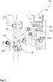
- FIG. 1 schematically a counter lock 100 of a lock assembly 500 according to the invention is shown in a front view.
- the FIGS. 2 to 5 show the counter lock 100 in further perspectives.
- Such a counter-lock 100 can preferably be used for a standing-wing door, in which a lock 1 of a revolving door is arranged adjacent to the counter-lock 100.
- a lock 1 of a corresponding arrangement is shown with dashed lines. It can be seen that, at the position of a locking element 20 of the lock 1, an opening 110 for the locking element 20 can be formed in a counter-lock housing 170.
- a corresponding opening 220 in particular latch opening 220, may be present in the counter lock housing 170.
- a cooperation of the lock 1 and counter lock 100 is achieved for locking.
- This arrangement is particularly suitable for escape doors or the like, since the operation of one of the actuators 141 (a nut or the like), possibly via a panic bar, can trigger a mechanical interaction of the counter lock 100 with the lock 1 for unlocking.
- a locking element actuator 130 of the counter lock 100 which is arranged adjacent to the opening 110 to push the locking element 20 out of the counter-lock housing 170.
- the locking element actuator 130 of the counter lock 100 is thereby moved from a retracted position to an operative position.
- the latch member actuator 130 is shown in the retracted position.
- a mechanism of the counter lock 100 can serve as an essential component for triggering this interaction, ie the unlocking of the lock 1 and the counter lock 100.
- This uses a counter-lock mechanism element 160, which is preferably designed as a slide 160.
- a movement of the slider 160 which in FIG. 1 is carried out as a translational guided in the counter lock housing 170 displacement (and a pivoting movement or the like are conceivable)
- more mechanical elements of the counter lock 100 - and in consequence of the lock 1 - can be actuated or unlocked.
- locking bars 520 of the counter lock 100, the locking element 20 and the case 70 may be mentioned, which will be discussed further below.
- a locking element 20 may as a means of locking at least one locking bar 520, ie z. B.
- a first locking bar 521 and a second locking bar 522 may be provided. These are associated with associated locking bar connections 120 of the counter lock 100, in particular immovably and firmly.
- the locking bar connections 120 are movably received in the counter lock housing 170 for movement of the locking bars 520.
- a first locking bar connection 121 for the first locking bar 521 and a second locking bar connection 122 for the second locking bar 522 are provided.
- the respective locking bar connection 120 can be moved by means of the slider 160 of the counter lock 100 from a first position to a second position.
- the locking bar 520 connected to the corresponding locking bar connection 120 can be extended and retracted in the second position in the counter-lock housing 170.
- a lock z. B. thereby allows the locking bar 520 in a Recording in a door frame, a wall, a ceiling, a floor or the like is introduced.
- the locking bar connection 120 For the unlocking, so the movement in the retracted position, thus the locking bar connection 120 must be moved to the second position.
- the slider 160 may be moved from a first position where the at least one latch bar port 120 is in the first position and to a second position where the at least one latch bar port 120 is in the second position.
- the counter lock 100 may comprise at least one counter-lock spring 180, which urges the slider 160 in the first position, wherein the counter-lock spring 180 engages at least one of the locking bar terminals 120.
- the slider 160 and the latch member actuator 130 are operatively connected to each other via a slotted guide.
- the latch member actuator 130 may have one or more functions, such as the movement of the latch member 20 of the adjacent latch 1 of a lock assembly 500 for unlocking and / or the tamper protection on the counter lock 100.
- the locking element 20 can engage in the opening 110 of the counter lock 100 in a locking position of the locking element 20.
- the lock 1 can comprise at least one control catch 50, for example with a rotatably mounted control case head 51, the control catch 50 assuming a retracted position for moving the locking element 20 into the locking position. In the projecting position of the control catch 50, however, the control catch 50 is mechanically prevented from moving the locking element 20 into the locking position.
- a strike plate 210 of the counter lock 100 may be provided so that closing the door results in retraction and retention of the control catch 50 by the strike plate 210.
- the latch member actuator 130 of the buckle 100 can be moved from the retracted position to the operative position. According to the latch member actuator 130 is formed in the operative position to hold the latch member 20 in the unlocked position until a control latch opening is removed from the strike plate 210 and the control latch 50 has reached the projecting position.
- the undesired return movement of the locking element 20 is caused by a lock mechanism element 33, which is designed as a slide 33.
- the slider 33 urges the locking element 20 by a lock spring in the locking position. In this case, the slider 33 moves from a first position to a second position. Due to the projecting position of the control latch 50, however, the movement of the slider 33 is prevented from the first layer to the second layer.
- the latch member actuator 130 can press out the latch member 20 by means of an active element 131 from the counter lock housing 170 by the movement into the operative position to support, for example, an emergency opening. Both can be effected mechanically by the connection of the locking element actuator 130 to the slider 160 by the slider 160 mechanically engages an engaging element 132 of the locking element actuator 130.
- the lock 1 is shown in more detail, which is also part of the lock assembly 500. It can be seen here that the lock 1 can have a lock housing 10, in which the slide 33 is movably guided. Further, a lock actuator 30 is provided with a lock gear 31 to move the slider 33 in particular. Also, the lock comprises a nut 32, by means of which the lock is mechanically unlocked.
- the actuation of the slide 33 can also cause the unlocking of a trap 70, which has a trap head 71.
- the further slide 33 can serve to move and / or guide the locking element 20, which may be influenced by a state of the latch 70 and the control latch 50.
- the locking element 20 z. B. only be transferred to the locking position when initially both the case 70 are transferred to the unlocking position and the tax trap 50 in the retracted position.
- a stop element 80 can change from a blocking position into a release position.
- the stop member 80 is movable independently of the position of the latch 70 from the release position to the blocking position by movement of the control latch 50. As a result, holding the locking element 20 in the unlocking position can already occur when the control catch 50 has reached the projecting position, regardless of a position of the latch 70.
- the latch element actuator 130 In the Figures 2 . 3 and 7 the latch element actuator 130 is shown in more detail. In the operative position of the locking element actuator 130 is resiliently against the locking element 20, and is for this purpose formed in several parts with a engagement element 132 and an active element 131 with an end face 134. A movement of the actuating device 140 of the counter lock 100 can move the engagement element 132, so that the active element 131 rests in the operative position on the locking element 20 with the end face 134. It is advantageous if the engagement element 132 and the active element 131 are resiliently connected to each other. A spring 135 of the latch element actuator 130 may be designed as a spiral spring for this purpose.
- the engagement element 132 may be pivotable together with the active element 131 about a first axis 162, wherein the active element 131 is pivotally mounted about a second axis 163 on the engagement element 132.
- the spring 135, which causes a suspension between engagement element 132 and active element 131, is designed as a leaf spring (see FIG. 6 ).
- a counter-lock mechanism part 161 connected to the actuating element 141 of the counter-lock 100 can engage a link 164 of the engagement element 132. A movement of the counter-lock mechanism part 161 in the link 164 causes the pivoting of the engagement element 132.
- the active element 131 is guided in the engagement element 132, wherein preferably the width of an end face 134 of the active element 131 is greater than a width of the active element 131 in the interior of the engagement element 132nd
- the active element 131 and the engagement element 132 may include mutually corresponding stop surfaces (ie, eg a first stop surface 138 and a second stop surface 139), wherein a movement of the active element 131 out of the engagement element 132 is limited by the stop surfaces.
- the width of the end face 134 of the locking element actuator 130 and the width of an end face 21 of the locking element 20 may further be formed such that at least one edge of the end face 134 of the locking element actuator 130, the inner side of the passive leaf is zuwendbar, and an edge of the end face 21 of the locking element 20, which is the outer side of the active leaf turnable, lie against each other when the control latch 50 is in the projecting position.
- the spring force of the spring 135 may be designed so that the active element 131 is always resiliently applied to the locking element 20, even if the unlocking is carried out against a preload. The resilient concern also takes place even when the latch 70 is transferred from a locked state to an unblocked state. For this purpose, a spring force of about 10 N may be necessary.
- the lock 1 according to FIG. 8 includes a latch element sensor 650, and an alarm is generated when an in FIG. 9 shown control case sensor 600 detects that the control latch 50 is in the protruding position and at the same time the locking element sensor 650 detects that the locking element 20 is in the locked position.
- the latch member actuator 130 may include a blocking surface 133 which, in the retracted position, blocks movement of at least one of the latch bar terminals 120 to the second position. Thus, an unauthorized retraction of the corresponding locking bar 520 can be prevented.
- the latch member actuator 130 may include a support surface 136 for guiding the slider 160.
- the lock 1 may comprise an electromechanical lock actuator 30 for moving the locking element 20.
- the control case sensor 600 may detect whether the control latch 50 is in the protruding position. Only then can the lock actuator terminate an operative connection with the slide, in particular in the first position.
- a counter-lock actuator 142 for moving at least one of the locking bars 520 are activated such that the Schlossaktuator 30 at least partially moves the locking element 20.
- the actuators of a locking system 400 can be controlled in a coordinated manner.
- z. B. an in FIG. 8 illustrated controller 510 is used, which is integrated, for example, in a door drive 410 (outside a locking assembly 500) and / or a first control unit 511 in the lock 1 and / or a second control unit 512 in the counter lock 100 includes.
- the controller 510 is electrically connected to the lock actuator 30 and / or counter-lock actuator 142 to perform the activation of the actuators.
- At least one of the latch bar terminals 120 may be connected to the slider 160 at play, and preferably to rest on a third projection 193 of the slider 160.
- the locking bar connection 120 then comes first on a blocking surface 133 of the locking element actuator 130 to rest before a transmission of movement to the slider 160 is possible.
- the connection between the locking bar connection 120 and the slider 160 may be made so that the slider 160 first moves the latch member actuator 130 and only then the latch bar terminal 120.
- At least one further of the locking bar connections 120 can be connected to the slider 160 via a lever 150.
- a lever 150 mounted in a pivot point 152, can forward the movement of the slide 160 to this additional locking bar connection 120.
- the movement of several (at least two) locking bar connections 120 via a single slider 160 reliably possible.
- the movement of a locking bar connection 120 can be effected by actuating an actuating device 140, that is, for example, by the actuation of the actuating element 141 and / or an electromechanical counter-lock actuator 142.
- the actuating element 141 is z. B. formed as a nut 141 and acts on a rotation of the slider 160.
- the Martinezeckuator 142 z. B. is designed as a motor and then has a counter-lock gear 200, via which it is operatively connected to the slider 160.
- the countershaft transmission 200 includes a cam 201, wherein, when the Jacobixaktuator 142 is in operative connection with the slider 160, the counter-lock gear 200 rests with the cam 201 on the slider 160.
- the slider 160 may include a first projection 191, on which the cam 201 comes to rest.
- this z. B. is designed as a motor, having an energy storage 105 (as in FIG. 8 is shown schematically).
- a control of the Gegenschaktuators 142 is z. B. via a controller 510, in particular a first control unit 511 of the lock 1 and / or a second control unit 512 of the counter lock 100 conceivable.
- the actuating element 141 can abut on a counter-lock mechanism element 160, in particular on a second projection 192 of the counter-lock mechanism element 160 in an idle state of the counter-lock actuator 142 and in an actuation position of the actuating element 141 (for example, the slider 160 can be considered as a counter-lock mechanism element 160) ).
- the actuating element 141 can pass out of operative connection with the slide 160 by an actuation of the counter-lock actuator 142.
- the slider 160 may be forcibly guided on the counter lock housing 170, in particular two times forcibly guided.
- For guiding the slider 160 may have at least one slot 194, wherein the pivot point 152 of the lever 150 may serve as a guide element for the slider 160 at the same time.
- the slider 160 it is also possible for the slider 160 to be contacted and / or abutted directly on the latch element actuator 130 and / or at least one of the latch rod connections 120, and the latch element actuator 130 can be moved by means of the slider 160, for which purpose the latch element actuator 130 is moved by the slide 160 via a slide element Kulisse 195 is forced.
- FIG. 1 a plurality of openings 173 shown in which through-fittings can be introduced for the attachment of standard coverings.
- the openings 173 may be provided that this corresponds to a specification for standard coverings.
- the screw-through connections can also serve to guide the slide 160, so that here there is a (at least) dual functionality of the openings.
Landscapes
- Engineering & Computer Science (AREA)
- Mechanical Engineering (AREA)
- Business, Economics & Management (AREA)
- Emergency Management (AREA)
- Structural Engineering (AREA)
- Lock And Its Accessories (AREA)
Abstract
Description
- Die vorliegende Erfindung betrifft eine Schlossanordnung gemäß der im Oberbegriff des Anspruchs 1 näher definierten Art.
- Es sind aus dem Stand der Technik Türen mit einer Stand- und einer Gangflügeltür bekannt, bei denen ein Schloss der Gangflügeltür benachbart zu einem Gegenschloss der Standflügeltür angeordnet ist. Dies ermöglicht es, dass ein Riegelelement des Schlosses in das Gehäuse des Gegenschlosses einfahren kann, um eine Verriegelung zu bewirken. Ferner ist es auch bekannt, dass die Verriegelung und/oder Entriegelung durch eine Steuerfalle des Schlosses gesteuert wird.
- Nachteilhaft bei den bekannten Lösungen für solche Schlossanordnungen ist, dass bei einem Öffnungsvorgang der Tür die Steuerfallen-Mechanik unter Umständen nicht zuverlässig die Entriegelung ermöglicht. Insbesondere ist bei geöffneter Tür eine Überführung des Riegelelements in die Verriegelungsstellung problematisch, da dies ein erneutes Verschließen der Tür blockiert. Eine erneute Überführung in die Verriegelungsstellung wäre z. B. möglich, wenn die Steuerfalle zu lange bei einem Öffnungsvorgang eine eingezogene Position einnimmt.
- Es ist daher eine Aufgabe der vorliegenden Erfindung, die voranstehend beschriebenen Nachteile zumindest teilweise zu beheben. Insbesondere ist es Aufgabe der vorliegenden Erfindung, bei einem Öffnungsvorgang der Tür zuverlässig die Überführung des Riegelelements in die Entriegelungsstellung zu gewährleisten.
- Die voranstehende Aufgabe wird gelöst durch eine Schlossanordnung mit den Merkmalen des Anspruchs 1. Weitere Merkmale und Details der Erfindung ergeben sich aus den jeweiligen Unteransprüchen, der Beschreibung und den Zeichnungen. Ebenfalls wird eine Tür mit einer erfindungsgemäßen Schlossanordnung unter Schutz gestellt.
- Die Aufgabe wird gelöst durch eine Schlossanordnung mit einem Schloss für eine Gangflügeltür und mit einem Gegenschloss für eine Standflügeltür. Dabei umfasst das Schloss zumindest ein Riegelelement, wobei das Riegelelement in einer Verriegelungsstellung des Riegelelements in eine Öffnung des Gegenschlosses eingreift. Vorzugsweise steht in einer Entriegelungsstellung des Riegelelements das Riegelelement außer Eingriff mit der Öffnung des Gegenschlosses und/oder ist außerhalb eines Gegenschlossgehäuses angeordnet.
- Ferner umfasst das Schloss zumindest eine Steuerfalle, wobei zur Bewegung des Riegelelements in die Verriegelungsstellung die Steuerfalle eine eingezogene Position einnimmt, wobei in einer abragenden Position der Steuerfalle die Bewegung des Riegelelements in die Verriegelungsstellung verhindert ist. Die abragende Position dient insbesondere dazu, eine offene Gangflügeltür festzustellen, wohingegen die eingezogene Position dazu dient, einen geschlossenen Zustand der Tür zu erkennen.
- Weiter umfasst das Gegenschloss einen Riegelelementbetätiger, wobei der Riegelelementbetätiger von einer zurückgezogenen Position in eine Wirkposition bewegbar ist. Das Gegenschloss umfasst ein Schließblech zum Halten der Steuerfalle in der eingezogenen Position. Das Schließblech kann somit die eingezogene Position der Steuerfalle im geschlossenen Zustand der Tür bewirken. Hierbei ist vorgesehen, dass der Riegelelementbetätiger dazu ausgebildet ist, in der Wirkposition das Riegelelement in der Entriegelungsstellung zu halten, bis die Steuerfalle, insbesondere bei einem Öffnungsvorgang der Tür, die abragende Position erreicht hat. Insbesondere hält der Riegelelementbetätiger in der Wirkposition das Riegelelement solange in der Entriegelungsstellung, bis die Steuerfalle die abragende Position durch eine zunehmende Entfernung des Schlosses und des Gegenschlosses zueinander erreicht hat. Bevorzugt kann eine Steuerfallenöffnung in einem Schlossgehäuse des Schlosses, durch das die Steuerfalle von der eingezogenen Position in die abragende Position bewegbar ist, sich von dem Schließblech des Gegenschlosses entfernen, wodurch die Steuerfalle sich von der eingezogenen Position in die abragende Position bewegen kann. Während der Riegelelementbetätiger in der Wirkposition das Riegelelement hält, kann die Steuerfalle sich an dem Schließblech abstützen, insbesondere entlang des Schließblechs gleiten. Das Schließblech kann geschlossen, insbesondere eben, in dem Bereich, in dem die Steuerfalle sich an dem Schließblech abstützen kann, ausgebildet sein.
- Die erfindungsgemäße Lösung hat den Vorteil, dass zuverlässig ein Öffnen und ein erneutes Schließen der Tür ermöglicht wird, da eine ungewünschte Bewegung des Riegelelements von der Entriegelungsstellung in die Verriegelungsstellung bei geöffneter Tür verhindert werden kann. Dadurch, dass der Riegelbetätiger das Riegelelement zuverlässig in der Entriegelungsstellung hält, bis die Steuerfalle die abragende Position erreicht hat, kann sichergestellt werden, dass zunächst die Steuerfalle diejenige Position einnimmt, in der das Riegelelement in der Entriegelungsstellung verbleibt, bevor der Riegelelementbetätiger aufhört, das Riegelelement in der Entriegelungsstellung zu halten. Somit wird insbesondere eine Wechselwirkung zwischen dem Riegelelementbetätiger und dem Riegelelement erst aufgehoben, wenn auch ohne den Riegelelementbetätiger das Riegelelement in der Entriegelungsstellung verbleibt.
- Es ist durchaus möglich, dass die Steuerfalle die abragende Position erreicht und dennoch mit einer Spitze an dem Schließblech anliegt, wobei der Riegelelementbetätiger dann aufhört oder aufhören kann, das Riegelelement in der Entriegelungsstellung zu halten. Der Riegelelementbetätiger ist demnach dazu ausgebildet, in der Wirkposition das Riegelelement in der Entriegelungsstellung zu halten, bis die Steuerfalle die abragende Position erreicht hat, wobei die Steuerfalle die abragende Position erreicht, indem das Schloss, insbesondere die Steuerfallenöffnung des Schlosses, sich von dem Schließblech entfernt.
- Beispielsweise kann das Schloss ein Schlossmechanikelement, insbesondere einen Schlossschieber, umfassen, durch den das Riegelelement in der Entriegelungsstellung gehalten ist. Die Steuerfalle verhindert in der abragenden Position, dass das Schlossmechanikelement derart bewegbar ist, dass das Riegelelement in die Verriegelungsstellung bewegbar ist.
- Das Schlossmechanikelement kann insbesondere derart wirkverbunden mit dem Riegelelement sein, dass eine Bewegung des Schlossmechanikelements von einer ersten Lage in eine zweite Lage eine Bewegung des Riegelelements von der Entriegelungsstellung in die Verriegelungsstellung bewirkt. Zusätzlich oder alternativ kann die Bewegung des Schlossmechanikelements von der zweiten Lage in die erste Lage eine Bewegung des Riegelelements von der Verriegelungsstellung in die Entriegelungsstellung bewirken. Die Steuerfalle kann in der abragenden Position bewirken, dass das Schlossmechanikelement in der ersten Lage verbleibt.
- Das Riegelelement und das Schlossmechanikelement können z. B. über eine Kulisse miteinander wechselwirken.
- Das Riegelelement kann als Riegel, als Falle oder als Fallenriegel ausgebildet sein.
- Eine Betätigungsvorrichtung des Gegenschlosses kann genutzt werden, um die Tür, die Gangflügeltür und/oder die Standflügeltür, zu öffnen und/oder zu entriegeln, wobei die Betätigungsvorrichtung außerdem die Bewegung des Riegelelementbetätigers von der zurückgezogenen Position in die Wirkposition bewirken kann.
- Von Vorteil kann sich dabei die Steuerfallenöffnung von dem Schließblech durch eine Öffnungsbewegung der Stand- und/oder der Gangflügeltür entfernen. Die Entfernung der Steuerfallenöffnung von dem Schließblech erfolgt insbesondere durch den größer werdenden Abstand zwischen dem Schloss und dem Schließblech. Dieses kann insbesondere der Fall sein, wenn sowohl die Gangflügeltür und die Standflügeltür gleichzeitig eine Öffnungsbewegung ausführen. Eine gleichzeitige Öffnungsbewegung kann erfolgen, wenn es sich um eine überfalzte Tür handelt und die Tür über die Standflügeltür geöffnet wird. Insbesondere kann die Steuerfalle bei Erreichen der abragenden Position an dem Schließblech anliegen.
- Es ist denkbar, dass bei einem Schließen der Tür die Bewegung des Riegelelements in die Verriegelungsstellung stets aktiviert wird. Das Schloss kann somit als ein selbstverriegelndes Schloss ausgebildet sein. Hierbei kann stets das Riegelelement in die Verriegelungsstellung ausgefahrenen werden, wenn sich das Schloss gegenüber dem Gegenschloss befindet. Das Schloss kann insbesondere als Anti-Panik Schloss ausgebildet sein. Hierbei kann das Schloss mechanisch durch die Betätigung einer Panikstange oder eines Türdrückers entriegelbar sein. Die Panikstange und/oder der Türdrücker können mit dem Schloss, insbesondere mit einem Betätigungselement des Schlosses, verbindbar sein.
- Das Gegenschloss kann insbesondere als selbstverriegelndes Gegenschloss ausgebildet sein. Hierbei kann stets zumindest eine Riegelstange von einer eingefahrenen Position in eine ausgefahrene Position bewegt werden, wenn sich die Riegelstange gegenüber von einem Schließelement für die Riegelstange befindet. Die Riegelstange kann mit dem Gegenschloss verbindbar sein. Das Gegenschloss kann insbesondere als ein Anti-Panik-Gegenschloss ausgebildet sein. Hierbei kann über eine Betätigung einer Panikstange oder eines Türdrückers am Gegenschloss sowohl die Standflügeltür als auch die Gangflügeltür öffenbar sein, insbesondere sich der Riegelelementbetätiger von der zurückgezogenen Position in die Wirkposition bewegen. Zusätzlich kann bei einer Betätigung einer Panikstange oder eines Türdrückers die Riegelstange von der ausgefahrenen Position in die eingefahrene Position bewegbar sein. Die Panikstange und/oder der Türdrücker können mit dem Gegenschloss, insbesondere mit einem Betätigungselement des Gegenschlosses, verbindbar sein.
- Weiter ist es denkbar, dass die Bewegung des Riegelelements in die Verriegelungsstellung durch eine Feder des Schlosses erfolgt und/oder unterstützt wird. Dies ermöglicht ggf. einen Mechanismus, bei welchem das Riegelelement von der Entriegelungsstellung in die Verriegelungsstellung wechselt, wenn sich die Steuerfalle in der eingezogenen Position und der Riegelelementbetätiger in der zurückgezogenen Position befindet.
- Der Riegelelementbetätiger ist insbesondere von der zurückgezogenen Position in die Wirkposition und umgekehrt bewegbar. In der zurückgezogenen Position lässt der Riegelelementbetätiger eine Bewegung des Riegelelements in die Verriegelungsstellung zu. In der Wirkposition verhindert der Riegelelementbetätiger, dass das Riegelelement die Verriegelungsstellung einnehmen kann. In der Wirkposition hält der Riegelelementbetätiger das Riegelelement in der Entriegelungsstellung. Wird mittels des Gegenschlosses das Riegelelement von der Verriegelungsstellung in die Entriegelungsstellung überführt werden, so bewegt sich insbesondere der Riegelelementbetätiger von der zurückgezogenen Position in die Wirkposition.
- Außerdem kann es im Rahmen der Erfindung von Vorteil sein, dass der Riegelelementbetätiger in der Wirkposition federnd an dem Riegelelement anliegt.
- Der Riegelelementbetätiger kann mehrteilig ausgebildet sein, wobei vorzugsweise der Riegelelementbetätiger ein Angriffselement und ein Wirkelement umfasst. Bevorzugt wird bei einer Bewegung einer Betätigungsvorrichtung des Gegenschlosses das Angriffselement. In der Wirkposition liegt das Wirkelement an dem Riegelelement an. Hierbei können das Angriffselement und das Wirkelement federnd miteinander verbunden sein. Hierdurch kann flexibel eine Position zum Anliegen am bzw. einen Abstand zum Riegelelement ausgeglichen werden. Dies hat den Vorteil, dass die Mechanik besonders zuverlässig über eine Bewegung des Riegelelementbetätigers das Riegelelement aus dem Gegenschlossgehäuse herausschieben und in der Entriegelungsstellung halten kann, solange bis die Steuerfalle die abragende Position erreicht hat. Hierbei muss die Feder zwischen dem Wirkelement und dem Angriffselement einen immer größer werdenden Spalt zwischen dem Schloss und dem Schließblech ausgleichen.
- Es kann optional möglich sein, dass der Riegelelementbetätiger translatorisch bewegbar ist. Das Wirkelement kann als ein Betätigungsstift ausgebildet sein, wobei insbesondere eine Feder des Riegelelementbetätigers als eine Spiralfeder ausgebildet ist.
- Der Betätigungsstift kann zur Deblockade des Riegelelements ausgebildet sein. Es ist denkbar, dass das Riegelelement in der Verriegelungsstellung blockiert ist. Hierzu kann ein Blockadeelement in dem Schloss vorgesehen sein. Das Wirkelement kann die Deblockade durchgeführen, z. B. indem das Wirkelement auf ein Deblockadeelement des Riegelelements drückt. Die Federkraft der Feder kann die Deblockade unterstützen.
- Vorteilhafterweise kann bei der Erfindung vorgesehen sein, dass das Wirkelement in dem Angriffselement geführt ist, insbesondere wenn der Riegelelementbetätiger translatorisch bewegbar ist.
- Bevorzugt kann die Breite einer Stirnfläche des Wirkelements größer ist als eine Breite des Wirkelementes im Inneren des Angriffselements sein. Hierdurch wird sowohl eine Führung des Wirkelements als auch eine hohe Breite, mit der das Wirkelement an dem Riegelelement anliegt, erreicht. Durch die hohe Breite, mit der der Riegelelementbetätiger an dem Riegelelement anliegt, wird erreicht, dass auch bei einem zunehmenden Abstand des Schlosses und des Gegenschlosses der Riegelelementbetätiger das Riegelelement in der Entriegelungsstellung hält. Ferner kann auch die geometrische Ausbildung und Erstreckung des Wirkelements, also im Besonderen die Breite der Stirnfläche, an das Riegelelement angepasst sein.
- Das Wirkelement und das Angriffselement können zueinander korrespondierende Stoppflächen umfassen, wobei durch die Stoppflächen eine Bewegung des Wirkelements aus dem Angriffselement begrenzt ist. Die Begrenzung der Bewegung dient dabei insbesondere zur Gewährleistung einer zuverlässigen Funktion, da die Bewegung des Wirkelements und ggf. auch ein Herausragen des Wirkelements aus dem Angriffselement und/oder aus dem Gegenschlossgehäuse in der Wirkposition an die Anordnung des Gegenschlosses in Bezug auf das Schloss, insbesondere im teilweise geöffneten Zustand der Tür, und/oder an die Ausbildung des Riegelelements angepasst sein muss.
- Bevorzugt kann im Rahmen der Erfindung vorgesehen sein, dass der Riegelelementbetätiger mit dem Angriffselement und dem Wirkelement um eine erste Achse schwenkbar ist. Das Wirkelement kann um eine zweite Achse schwenkbar an dem Angriffselement gelagert sein, wobei insbesondere die Feder als Blattfeder ausgebildet ist. Die Feder ist zwischen dem Wirkelement und dem Angriffselement gelagert. Dies ermöglicht eine besonders platzsparende Ausbildung des Riegelelementbetätigers. Es kann sein, dass das Angriffselement eine Kulisse aufweist, über die das Angriffselement versschwenkt werden kann. In die Kulisse kann ein mit dem Betätigungselement des Gegenschlosses verbundenes Gegenschlossmechanikteil angreifen. Eine Bewegung des Gegenschlossmechanikteils in der Kulisse an die Bewegung des Angriffselements hervorrufen.
- In einer weiteren Möglichkeit kann vorgesehen sein, dass die Steuerfalle einen Steuerfallenkopf umfasst, der drehbar gelagert ist und/oder mit einer Spitze versehen ist. Von Vorteil ist es ferner, wenn der Steuerfallenkopf derart gelagert ist, dass die Drehung eine Bewegung der Steuerfalle in die abragende Position Position erleichtert. Dies vereinfacht die Bereitstellung der Funktionalität der Steuerfalle, bei einem Öffnen der Tür herauszuragen und somit bspw. eine Überführung des Riegelelements in die Verriegelungsstellung im zumindest teilweise offenen Zustand der Tür zu verhindern.
- Es kann weiter möglich sein, dass ein Abraganteil des Riegelelementbetätigers, der in der Wirkposition aus dem Schließblech hervorsteht, zumindest 45 % eines Abraganteils der Steuerfalle, mit der die Steuerfalle in der abragenden Position aus dem Schloss hervorsteht, beträgt, bevorzugt, dass der Abraganteil des Riegelelementbetätigers zumindest 50% des Abraganteils der Steuerfalle beträgt, besonders bevorzugt, dass der Abraganteil des Riegelelementbetätigers zumindest 55% des Abraganteils der Steuerfalle beträgt. Als obere Grenze kann der Abgraganteil des Riegelelementbetätigers z. B. 100 % des Abraganteils der Steuerfalle betragen. Dies hat den Vorteil, dass das Riegelelement zuverlässig beim Öffnungsvorgang in der Entriegelungsstellung gehalten wird. Hierbei kann der Abraganteil des Riegelelementbetätigers zum Quadrat und/oder die Breite des Schließblechs oder des Gegenschlosses zum Quadrat ungefähr dem Abraganteil der Steuerfalle zum Quadrat entsprechen. Mit "ungefähr" ist ein Bereich +/- 20%, bevorzugt +/- 10 % gemeint.
- Auch ist es optional denkbar, dass die Breite einer Stirnfläche des Riegelelementbetätigers und die Breite einer Stirnfläche des Riegelelements derart ausgebildet sind, dass zumindest eine Kante der Stirnfläche des Riegelelementbetätigers, die insbesondere der Innenseite der Standflügeltür zuwendbar ist, und eine Kante der Stirnfläche des Riegelelements, die vorzugsweise der Außenseite der Gangflügeltür zuwendbar ist, aneinander liegen, wenn die Steuerfalle sich in der abragenden Position befindet.
- Besonders bevorzugt beträgt die Stirnfläche des Riegelelementbetätigers zumindest 80% der Breite des Gegenschlosses der des Schließblechs. Hierdurch wird der Vorteil erzielt, dass während des Öffnungsvorgangs der Tür das Riegelelement zuverlässig von dem Wirkelement des Riegelelementbetätigers in der Entriegelungsstellung gehalten wird, solange die Steuerfallenöffnung sich noch nicht von dem Schließblech entfernt und die abragende Position erreicht hat. Denn insbesondere kann erst dann mit dem Erreichen der abragenden Position gewährleistet sein, dass das Riegelelement auch ohne durch den Riegelelementbetätiger gehalten wird und nicht erneut in die Verriegelungsstellung überführt wird, also in der Entriegelungsstellung verbleibt.
- Außerdem ist es von Vorteil, wenn eine Feder des Riegelelementbetätigers, insbesondere die Federkraft der Feder, derart ausgelegt ist, dass der Riegelelementbetätiger während der Bewegung des Riegelelements in die Entriegelungsstellung stets federnd an dem Riegelelement anliegt, insbesondere dass der Riegelelementbetätiger dann federnd an dem Riegelelement anliegt, wenn der Entriegelungsvorgang gegen eine Vorlast (vorzugsweise am Riegelelement) durchgeführt wird. Hierbei ist vorteilhafterweise vorgesehen, dass das Riegelelement einem Riegel des Schlosses entspricht. Insbesondere kann die Feder derart ausgelegt sein, dass auch bei einer Vorlast ein Hinausdrücken des Riegelelements aus dem Gegenschlossgehäuse möglich ist.
- Es kann ferner möglich sein, dass das Schloss eine Falle umfasst. Die Falle kann in eine Verriegelungsposition und in eine Entriegelungsposition bewegbar sein.
- Die Falle kann insbesondere in einen blockierten Zustand und in einen unblockierten Zustand überführbar sein, wobei vorzugsweise die Falle in dem unblockierten Zustand bei Anlage an einen Rand einer Fallenöffnung des Gegenschlosses oder an ein Schließblech des Gegenschlosses in die Entriegelungsposition bewegbar ist und/oder in dem blockierten Zustand eine Bewegung in die Entriegelungsposition verhindert ist. Beispielsweise kann die Falle als eine Kreuzfalle ausgebildet sein.
- Eine Feder des Riegelelementbetätigers, insbesondere die Federkraft der Feder, kann derart ausgelegt sein, dass der Riegelelementbetätiger während der Bewegung des Riegelelements in die Entriegelungsstellung federnd an dem Riegelelement anliegt, während die Falle in den unblockierten Zustand überführt wird. Damit hat das Halten und/oder Herausdrücken des Riegelelements durch den Riegelelementbetätiger den Vorteil, dass die Überführung in den unblockierten Zustand durch den Riegelelementbetätiger gewährleistet wird. Bspw. ist hierzu eine entsprechende Mechanik im Schloss vorgesehen, welche nur bei dieser Bewegung des Riegelelements in die Entriegelungsstellung und/oder bei Vorliegen der Entriegelungsstellung des Riegelelements diese Überführung in den unblockierten Zustand ermöglicht. Dies ermöglicht ferner ein zuverlässiges Öffnen der entriegelten Tür, da die Falle sich z. B. von der Fallenöffnung wegbewegen kann. Bspw. beträgt hierzu die Federkraft ungefähr 10 N oder liegt in einem Bereich von 8 N bis 12 N (Newton).
- Des Weiteren ist es denkbar, dass das Gegenschloss ein Gegenschlossmechanikelement, insbesondere einen Schieber, umfasst, wobei mittels des Gegenschlossmechanikelements der Riegelelementbetätiger und/oder eine Riegelstange, insbesondere über einen Riegelstangenanschluss, bewegbar sind, insbesondere dass das Gegenschlossmechanikelement unmittelbar mit dem Riegelelementbetätiger und/oder mit der Riegelstange und/oder dem Riegelstangenanschluss verbunden ist und/oder daran kontaktiert. Alternativ oder zusätzlich kann es möglich sein, dass das Gegenschlossmechanikelement über einen Hebel mit einer zweiten Riegelstange und/oder einem zweiten Riegelstangenanschluss verbunden ist und/oder daran kontaktiert. Vorzugsweise kann die zweite Riegelstange bzw. der zweite Riegelstangenanschluss über den Hebel mittels des Gegenschlossmechanikelements von der ausgefahrenen in die eingefahrene Position bzw. von einer ersten in eine zweite Position überführbar ist. Hierdurch kann eine zusätzliche Verriegelung zur weiteren Erhöhung der Sicherheit bei der Tür ermöglicht werden.
- Ein weiterer Vorteil im Rahmen der Erfindung ist erzielbar, wenn das Riegelelement nur in die Verriegelungsstellung überführbar ist, wenn zunächst sowohl die Falle in die Entriegelungsposition als auch die Steuerfalle in die eingezogene Position überführt werden, wodurch ein Stoppelement von einer Sperrstellung in eine Freigabestellung wechseln kann, wobei vorzugsweise das Stoppelement unabhängig von der Position der Falle durch eine Bewegung der Steuerfalle von der eingezogenen Position in die abragende Position, insbesondere während sich das Riegelelement in der Entriegelungsstellung befindet, von der Freigabestellung in die Sperrstellung bewegbar ist. Das Schloss kann das Stoppelement umfassen.
- Damit kann das Stoppelement vorteilhafterweise in der Sperrstellung zum Sperren einer Überführung des Riegelelements von der Entriegelungsstellung in die Verriegelungsstellung ausgeführt sein. Hierzu kann das Stoppelement z. B. in eine Ausnehmung des Riegelelements eingreifen.
- Das Stoppelement kann in der Freigabestellung zum Freigeben der Überführung des Riegelelements von der Entriegelungsstellung in die Verriegelungsstellung ausgeführt sein. Beispielsweise kann sich das Stoppelement in der Freigabestellung außer Eingriff mit der Ausnehmung des Riegelelements befinden.
- Hierzu kann das Stoppelement bspw. durch die Mechanik im Schloss von der Sperrstellung in die Freigabestellung wechseln, vorzugsweise derart, dass nur in der Sperrstellung die Bewegung des Riegelelements direkt oder indirekt durch das Stoppelement blockiert wird.
- Auch ist es optional denkbar, dass die Falle mit einem derart beweglichen Fallenkopf ausgebildet ist, dass die Falle, insbesondere bei einer Öffnungsbewegung der Gangflügeltür und/oder der Standflügeltür, bei Anlage an einen Rand einer Fallenöffnung oder an das Schließblech in die Entriegelungsposition bewegbar ist. Alternativ oder kombinativ kann es möglich sein, dass die Falle nur durch die Anlage an den Rand der Fallenöffnung oder an das Schließblech in die Entriegelungsposition bewegbar ist. Insbesondere kann dabei das Gegenschloss frei von einem Fallenbetätiger ausgebildet sein.
- Ein weiterer Vorteil kann im Rahmen der Erfindung erzielt werden, wenn das Schloss einen elektromechanischen Schlossaktuator und einen Steuerfallensensor umfasst, wobei das Riegelelement solange von dem Schlossaktuator in der Entriegelungsstellung gehalten ist, bis mittels des Steuerfallensensors detektiert ist, dass die Steuerfalle sich in der abragenden Position befindet. Auch hierdurch kann die zuverlässige Funktion des Schlosses beim Öffnen der Tür gewährleistet werden.
- Weiter ist im Rahmen der Erfindung denkbar, dass das Schloss einen Riegelelementsensor umfasst und ein Alarm generiert wird, wenn der Steuerfallensensor detektiert, dass sich die Steuerfalle in der abragenden Position befindet und insbesondere der Riegelelementsensor detektiert, dass sich das Riegelelement in der Verriegelungsstellung befindet. Damit kann eine fehlerhafte Verriegelung zuverlässig festgestellt werden.
- Weitere Vorteile, Merkmale und Einzelheiten der Erfindung ergeben sich aus der nachfolgenden Beschreibung, in der unter Bezugnahme auf die Zeichnungen Ausführungsbeispiele der Erfindung im Einzelnen beschrieben sind. Dabei können die in den Ansprüchen und in der Beschreibung erwähnten Merkmale jeweils einzeln für sich oder in beliebiger Kombination erfindungswesentlich sein. Es zeigen:
- Fig. 1
- eine Darstellung eines Gegenschlosses einer erfindungsgemäßen Schlossanordnung in einer Vorderansicht,
- Fig. 2
- eine vergrößerte Darstellung von Teilen des Gegenschlosses aus
Figur 1 in einer Rückansicht, - Fig. 3
- eine vergrößerte Darstellung von Teilen des Gegenschlosses aus
Figur 1 in einer Vorderansicht, - Fig. 4
- eine Darstellung des Gegenschlosses aus
Figur 1 in einer perspektivischen Ansicht, - Fig. 5
- eine weitere Darstellung des Gegenschlosses aus
Figur 1 in einer perspektivischen Ansicht, - Fig. 6
- eine Darstellung eines weiteren Gegenschlosses einer erfindunsgemäßen Schlossanordnung in einer perspektivischen Ansicht,
- Fig. 7
- eine Explosionsdarstellung des Gegenschlosses aus
Figur 1 , - Fig. 8
- eine Darstellung einer erfindungsgemäßen Schlossanordnung mit einem Gegenschlosses und einem Schlosses,
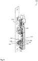
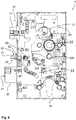
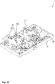
- Fig. 9
- eine Ansicht eines Schlosses einer erfindungsgemäßen Schlossanordnung, wobei das Gegenschloss gemäß einem der
Figuren 1 bis 8 ausgebildet sein kann, und - Fig. 10
- eine perspektivische Ansicht des Schlosses aus
Figur 9 . - In den nachfolgenden Figuren werden für die gleichen technischen Merkmale auch von unterschiedlichen Ausführungsbeispielen die identischen Bezugszeichen verwendet.
- In
Figur 1 ist schematisch ein Gegenschloss 100 einer erfindungsgemäßen Schlossanordnung 500 in einer Vorderansicht gezeigt. DieFiguren 2 bis 5 zeigen das Gegenschloss 100 in weiteren Perspektiven. Ein derartiges Gegenschloss 100 kann bevorzugt für eine Standflügeltür eingesetzt werden, bei welchem benachbart zum Gegenschloss 100 ein Schloss 1 einer Gangflügeltür angeordnet ist. Beispielhaft ist daher ein solches Schloss 1 einer entsprechenden Anordnung mit gestrichelten Linien dargestellt. Es ist erkennbar, dass an der Position eines Riegelelements 20 des Schlosses 1 eine Öffnung 110 für das Riegelelement 20 in einem Gegenschlossgehäuse 170 ausgebildet sein kann. Genauso kann an der Position eines zweiten Riegelelements 70 (wie einer Falle 70) eine entsprechende Öffnung 220, insbesondere Fallenöffnung 220, im Gegenschlossgehäuse 170 vorhanden sein. Somit wird eine Zusammenwirkung des Schlosses 1 und Gegenschlosses 100 zur Verriegelung erzielt. Diese Anordnung eignet sich dabei besonders für Fluchttüren oder dergleichen, da die Betätigung einer der Betätigungselemente 141 (einer Nuss oder dergleichen), ggf. über eine Panikstange, eine mechanische Wechselwirkung des Gegenschlosses 100 mit dem Schloss 1 zur Entriegelung auslösen kann. Beispielhaft sei hier ein Riegelelementbetätiger 130 des Gegenschlosses 100 angeführt, welcher benachbart zur Öffnung 110 angeordnet ist, um das Riegelelement 20 aus dem Gegenschlossgehäuse 170 herauszudrücken. Der Riegelelementbetätiger 130 des Gegenschlosses 100 wird hierbei von einer zurückgezogenen Position in eine Wirkposition bewegt. In den Figuren ist der Riegelelementbetätiger 130 in der zurückgezogenen Position dargestellt. - Als ein wesentlicher Bestandteil zur Auslösung dieser Wechselwirkung, also die Entriegelung des Schlosses 1 und des Gegenschlosses 100, kann ein Mechanismus des Gegenschlosses 100 dienen. Dieser nutzt ein Gegenschlossmechanikelement 160, welches vorzugsweise als ein Schieber 160 ausgebildet ist. Durch eine Bewegung des Schiebers 160, welche in
Figur 1 als eine translatorisch im Gegenschlossgehäuse 170 geführte Verschiebung ausgeführt ist (auch eine Schwenkbewegung oder dergleichen sind denkbar), können weitere mechanische Elemente des Gegenschlosses 100 - und in Folge auch des Schlosses 1 - betätigt bzw. entriegelt werden. Als Beispiel können hier Riegelstangen 520 des Gegenschlosses 100, das Riegelelement 20 sowie die Falle 70 genannt werden, worauf nachfolgend weiter eingegangen wird. - Alternativ oder zusätzlich zu einem Riegelelement 20 kann als Mittel zur Verriegelung wenigstens eine Riegelstange 520, also z. B. eine erste Riegelstange 521 und eine zweite Riegelstange 522, vorgesehen sein. Diese sind mit zugehörigen Riegelstangenanschlüssen 120 des Gegenschlosses 100, insbesondere unbeweglich und fest, verbunden. Die Riegelstangenanschlüsse 120 sind zur Bewegung der Riegelstangen 520 im Gegenschlossgehäuse 170 beweglich aufgenommen. Insbesondere ist ein erster Riegelstangenanschluss 121 für die erste Riegelstange 521 und ein zweiter Riegelstangenanschluss 122 für die zweite Riegelstange 522 vorgesehen. Dabei kann der jeweilige Riegelstangenanschluss 120 mittels des Schiebers 160 des Gegenschlosses 100 von einer ersten Position in eine zweite Position bewegt werden. In der ersten Position kann die mit dem entsprechenden Riegelstangenanschluss 120 verbundene Riegelstange 520 ausgefahren und in der zweiten Position im Gegenschlossgehäuse 170 eingefahren sein. In der ausgefahrenen Position wird eine Verriegelung z. B. dadurch ermöglicht, dass die Riegelstange 520 in einer Aufnahme in einem Türrahmen, einer Wand, einer Decke, einem Boden oder dergleichen eingebracht ist. Für die Entriegelung, also die Bewegung in die eingefahrene Position, muss somit der Riegelstangenanschluss 120 in die zweite Position bewegt werden.
- Der Schieber 160 kann von einer ersten Stellung, in der der wenigstens eine Riegelstangenanschluss 120 sich in der ersten Position befindet, und in eine zweite Stellung, in der sich der wenigstens eine Riegelstangenanschluss 120 in der zweiten Position befindet, bewegt werden. Hierbei kann das Gegenschloss 100 wenigstens eine Gegenschlossfeder 180 aufweisen, die den Schieber 160 in die erste Stellung drängt, wobei die Gegenschlossfeder 180 an wenigstens einem der Riegelstangenanschlüsse 120 angreift.
- Der Schieber 160 und der Riegelelementbetätiger 130 sind über eine Kulissenführung miteinander wirkverbunden.
- Der Riegelelementbetätiger 130 kann eine oder mehrere Funktionen aufweisen, wie die Bewegung des Riegelelements 20 des benachbarten Schlosses 1 einer Schlossanordnung 500 zur Entriegelung und/oder der Manipulationsschutz beim Gegenschloss 100. Wie in
Figur 8 anhand einer Schlossanordnung 500 eines Schließsystems 400 dargestellt ist, kann das Riegelelement 20 in einer Verriegelungsstellung des Riegelelements 20 in die Öffnung 110 des Gegenschlosses 100 eingreifen. Darüber hinaus kann das Schloss 1 zumindest eine Steuerfalle 50, bspw. mit einem drehbar gelagerten Steuerfallenkopf 51, umfassen, wobei zur Bewegung des Riegelelements 20 in die Verriegelungsstellung die Steuerfalle 50 eine eingezogene Position einnimmt. In der abragenden Position der Steuerfalle 50 ist die Steuerfalle 50 hingegen die Bewegung des Riegelelements 20 in die Verriegelungsstellung mechanisch verhindert. Zum Halten der Steuerfalle 50 in der eingezogenen Position kann ein Schließblech 210 des Gegenschlosses 100 vorgesehen sein, sodass ein Schließen der Tür zu einem Einfahren und Halten der Steuerfalle 50 durch das Schließblech 210 führt. - Der Riegelelementbetätiger 130 des Gegenschlosses 100 kann von der zurückgezogenen Position in die Wirkposition bewegt werden. Erfindungsgemäß ist in der Wirkposition der Riegelelementbetätiger 130 dazu ausgebildet, das Riegelelement 20 in der Entriegelungsstellung zu halten, bis eine Steuerfallenöffnung sich von dem Schließblech 210 entfernt und die Steuerfalle 50 die abragende Position erreicht hat.
- In anderen Worten kann verhindert werden, dass beim Öffnen der Tür, also dem Bewegen des Stand- und/oder Gangflügels, das Riegelelement 20 erneut in die Verriegelungsstellung bewegt wird. Zwar wird stets zunächst das Riegelelement 20 durch den Riegelelementbetätiger 130 in die Entriegelungsstellung überführt. Würde der Riegelelementbetätiger 130 außer Wirkverbindung mit dem Riegelelement 20 gelangen, bevor die Steuerfalle 50 die abragende Position erreicht, so würde das Riegelelement 20 ungewünschterweise erneut die Verriegelungsstellung einnehmen. Dieses wird erfindungsgemäß dadurch verhindert, dass der Riegelelementbetätiger 130 solange mit dem Riegelelement mitgeführt wird, bis die Steuerfalle 50 die abragende Position erreicht hat.
- Die unerwünschte Zurückbewegung des Riegelelements 20 wird durch ein Schlossmechanikelement 33, das als Schieber 33 ausgebildet ist, verursacht. Der Schieber 33 drängt durch eine Schlossfeder das Riegelelement 20 in die Verriegelungsstellung. Hierbei bewegt sich der Schieber 33 von einer ersten Lage in eine zweite Lage. Durch die abragende Position der Steuerfalle 50 jedoch wird die Bewegung des Schiebers 33 von der ersten Lage in die zweite Lage verhindert.
- Weiterhin kann der Riegelelementbetätiger 130 durch die Bewegung in die Wirkposition das Riegelelement 20 mittels eines Wirkelements 131 aus dem Gegenschlossgehäuse 170 herausdrücken, um bspw. eine Notöffnung zu unterstützen. Beides kann durch die Verbindung des Riegelelementbetätigers 130 zu dem Schieber 160 mechanisch bewirkt werden, indem der Schieber 160 mechanisch an einem Angriffselement 132 des Riegelelementbetätigers 130 angreift.
- In
Figur 9 und10 ist das Schloss 1 mit weiteren Einzelheiten dargestellt, welches ebenfalls Teil der Schlossanordnung 500 ist. Hierbei ist erkennbar, dass das Schloss 1 ein Schlossgehäuse 10 aufweisen kann, in welchem der Schieber 33 beweglich geführt ist. Weiter ist ein Schlossaktuator 30 mit einem Schlossgetriebe 31 vorgesehen, um insbesondere den Schieber 33 zu bewegen. Ebenfalls umfasst das Schloss eine Nuss 32, mittels derer das Schloss mechanisch entriegelbar ist. - Die Betätigung des Schiebers 33 kann zudem die Entriegelung einer Falle 70 bewirken, welche einen Fallenkopf 71 aufweist. Der weitere Schieber 33 kann zur Bewegung und/oder Führung des Riegelelements 20 dienen, was durch einen Zustand der Falle 70 und der Steuerfalle 50 beeinflusst sein kann. So kann das Riegelelement 20 z. B. nur dann in die Verriegelungsstellung überführt werden, wenn zunächst sowohl die Falle 70 in die Entriegelungsposition als auch die Steuerfalle 50 in die eingezogene Position überführt werden. Ein Stoppelement 80 kann hierzu von einer Sperrstellung in eine Freigabestellung wechseln. Das Stoppelement 80 ist unabhängig von der Position der Falle 70 von der Freigabestellung in die Sperrstellung durch eine Bewegung der Steuerfalle 50 bewegbar. Hierdurch kann das Halten des Riegelelements 20 in der Entriegelungsstellung bereits eintreten, wenn die Steuerfalle 50 die abragende Position erreicht hat, unabhängig von einer Position der Falle 70.
- In den
Figuren 2 ,3 und7 ist der Riegelelementbetätiger 130 mit weiteren Einzelheiten gezeigt. In der Wirkposition liegt der Riegelelementbetätiger 130 federnd an dem Riegelelement 20 an, und ist hierzu mehrteilig mit einem Angriffselement 132 und einem Wirkelement 131 mit einer Stirnfläche 134 ausgebildet. Eine Bewegung der Betätigungsvorrichtung 140 des Gegenschlosses 100 kann dabei das Angriffselement 132 bewegen, sodass das Wirkelement 131 in der Wirkposition an dem Riegelelement 20 mit der Stirnfläche 134 anliegt. Von Vorteil ist es, wenn das Angriffselement 132 und das Wirkelement 131 federnd miteinander verbunden sind. Eine Feder 135 des Riegelelementbetätigers 130 kann hierzu als eine Spiralfeder ausgebildet sein. - Als weitere Ausführungsvariante des Riegelelementbetätigers 130, die in
Figur 6 dargestellt ist, kann das Angriffselement 132 zusammen mit dem Wirkelement 131 um eine erste Achse 162 schwenkbar sein, wobei das Wirkelement 131 um eine zweite Achse 163 schwenkbar an dem Angriffselement 132 gelagert ist. Die Feder 135, die eine Federung zwischen Angriffselement 132 und Wirkelement 131 hervorruft, ist als Blattfeder ausgeführt (siehe hierzuFigur 6 ). Wie inFigur 6 dargestellt, kann ein mit dem Betätigungselement 141 des Gegenschlosses 100 verbundenes Gegenschlossmechanikteil 161 an eine Kulisse 164 des Angriffselements 132 angreifen. Eine Bewegung des Gegenschlossmechanikteils 161 in der Kulisse 164 ruft an das Verschwenken des Angriffselements 132 hervor. - Auf das Ausführungsbeispiel der
Figuren 1 bis 5 undFigur 7 zurückkommend, ist das Wirkelement 131 in dem Angriffselement 132 geführt, wobei bevorzugt die Breite einer Stirnfläche 134 des Wirkelements 131 größer ist als eine Breite des Wirkelements 131 im Inneren des Angriffselements 132. - Ferner kann das Wirkelement 131 und das Angriffselement 132 zueinander korrespondierende Stoppflächen (also z. B. eine erste Stoppfläche 138 und eine zweite Stoppfläche 139) umfassen, wobei durch die Stoppflächen eine Bewegung des Wirkelements 131 aus dem Angriffselement 132 begrenzt ist.
- Die Breite der Stirnfläche 134 des Riegelelementbetätigers 130 und die Breite einer Stirnfläche 21 des Riegelelements 20 können ferner derart ausgebildet sein, dass zumindest eine Kante der Stirnfläche 134 des Riegelelementbetätigers 130, die der Innenseite des Standflügels zuwendbar ist, und eine Kante der Stirnfläche 21 des Riegelelements 20, die der Außenseite des Gangflügels zuwendbar ist, aneinander liegen, wenn die Steuerfalle 50 sich in der abragenden Position befindet.
- Es ist ein weiterer Vorteil erzielbar, wenn ein in
Figur 7 gezeigter Abraganteil 137 des Riegelelementbetätigers 130, welcher in der Wirkposition aus einem Schließblech 210 hervorsteht, zumindest 45 % eines inFigur 9 dargestellten Abraganteils 52 der Steuerfalle 50, mit der die Steuerfalle 50 in der abragenden Position aus dem Schloss 1 hervorsteht, beträgt. - Die Federkraft der Feder 135 kann so ausgelegt sein, dass das Wirkelement 131 stets federnd an dem Riegelelement 20 anliegt, auch wenn die Entriegelung gegen eine Vorlast durchgeführt wird. Das federnde Anliegen findet auch dann noch statt, wenn die Falle 70 von einem blockierten Zustand in einen unblockierten Zustand überführt wird. Hierzu kann eine Federkraft von ca. 10 N notwendig sein.
- Weiterhin ist es möglich, dass das Schloss 1 gemäß
Figur 8 einen Riegelelementsensor 650 umfasst, und ein Alarm generiert wird, wenn ein inFigur 9 gezeigter Steuerfallensensor 600 detektiert, dass sich die Steuerfalle 50 in der abragenden Position befindet und gleichzeitig der Riegelelementsensor 650 detektiert, dass das Riegelelement 20 sich in der Verriegelungsstellung befindet. - Weiter kann der Riegelelementbetätiger 130 eine Blockadefläche 133 umfassen, welche in der zurückgezogenen Position eine Bewegung wenigstens eines der Riegelstangenanschlüsse 120 in die zweite Position blockiert. Damit kann ein unbefugtes Einziehen der entsprechenden Riegelstange 520 verhindert werden. Darüber hinaus kann der Riegelelementbetätiger 130 eine Auflagefläche 136 zur Führung des Schiebers 160 umfassen.
- In
Figur 9 ist weiter verdeutlicht, dass das Schloss 1 einen elektromechanischen Schlossaktuator 30 zum Bewegen des Riegelelements 20 aufweisen kann. Der Steuerfallensensor 600 kann detektieren, ob sich die Steuerfalle 50 in der abragenden Position befindet. Erst danach kann der Schlossaktuator eine Wirkverbindung mit dem Schieber insbesondere in der ersten Lage, beenden. - Es kann ferner gemäß
Figur 1 ein Gegenschlossaktuator 142 zur Bewegung wenigstens einer der Riegelstangen 520 derart aktiviert werden, dass der Schlossaktuator 30 zumindest teilweise das Riegelelement 20 bewegt. In anderen Worten können die Aktuatoren eines Schließsystems 400 koordiniert angesteuert werden. Hierzu kann z. B. eine inFigur 8 veranschaulichte Steuerung 510 genutzt werden, welche bspw. in einem Türantrieb 410 (außerhalb einer Schließanordnung 500) integriert ist und/oder eine erste Steuerungseinheit 511 im Schloss 1 und/oder eine zweite Steuerungseinheit 512 im Gegenschloss 100 umfasst. Insbesondere ist dabei die Steuerung 510 elektrisch mit dem Schlossaktuator 30 und/oder Gegenschlossaktuator 142 verbunden, um die Aktivierung der Aktuatoren durchzuführen. - Wie in
Figur 2 und3 weiter gezeigt ist, kann es möglich sein, dass wenigstens einer der Riegelstangenanschlüsse 120 mit einem Spiel mit dem Schieber 160 verbunden ist, und vorzugsweise auf einem dritten Vorsprung 193 des Schiebers 160 aufliegt. Dies dient z. B. dem Manipulationsschutz bei einer aktiven (von außen über die Riegelstangen 520 eingeleiteten) Bewegung des Riegelstangenanschlusses 120 in Richtung des Inneren des Gegenschlossgehäuses 170. Hierbei kommt der Riegelstangenanschluss 120 dann zunächst auf einer Blockadefläche 133 des Riegelelementbetätigers 130 zum Aufliegen, bevor eine Übertragung der Bewegung an den Schieber 160 möglich ist. Auch kann die Verbindung zwischen dem Riegelstangenanschluss 120 und dem Schieber 160 so ausgeführt sein, sodass der Schieber 160 zunächst den Riegelelementbetätiger 130 und erst dann den Riegelstangenanschluss 120 bewegt. - In
Figur 1 und7 ist zu sehen, dass wenigstens ein weiterer der Riegelstangenanschlüsse 120 über einen Hebel 150 mit dem Schieber 160 verbunden sein kann. Ein solcher Hebel 150 kann in einem Drehpunkt 152 gelagert die Bewegung des Schiebers 160 an diesen weiteren Riegelstangenanschluss 120 weiterleiten. Insbesondere ist auf diese Weise, einerseits über den Hebel 150 und andererseits über den dritten Vorsprung 193, zuverlässig die Bewegung mehrerer (wenigstens zweier) Riegelstangenanschlüsse 120 über einen einzigen Schieber 160 möglich. - Die Bewegung eines Riegelstangenanschlusses 120 kann durch eine Betätigung einer Betätigungsvorrichtung 140, also bspw. durch die Betätigung des Betätigungselements 141 und/oder eines elektromechanischen Gegenschlossaktuators 142, bewirkt werden. Das Betätigungselement 141 ist z. B. als Nuss 141 ausgebildet und wirkt bei einer Drehung auf den Schieber 160. Der Gegenschlossaktuator 142 ist z. B. als Motor ausgebildet und weist dann ein Gegenschlossgetriebe 200 auf, über den es mit dem Schieber 160 wirkverbindbar ist. Es ist beispielhaft dargestellt, dass das Gegenschlossgetriebe 200 einen Nocken 201 umfasst, wobei, wenn sich der Gegenschlossaktuator 142 in Wirkverbindung mit dem Schieber 160 befindet, das Gegenschlossgetriebe 200 mit dem Nocken 201 an dem Schieber 160 anliegt. Hierzu kann der Schieber 160 einen ersten Vorsprung 191 umfassen, an dem der Nocken 201 zur Anlage gelangt. Zur Betätigung kann der Gegenschlossaktuator 142, wenn dieser z. B. als Motor ausgebildet ist, einen Energiespeicher 105 aufweisen (wie in
Figur 8 schematisch dargestellt ist). Eine Ansteuerung des Gegenschlossaktuators 142 ist z. B. über eine Steuerung 510, insbesondere eine erste Steuerungseinheit 511 des Schlosses 1 und/oder eine zweite Steuerungseinheit 512 des Gegenschlosses 100 denkbar. - Es ist ferner denkbar, dass das Betätigungselement 141 in einem Ruhezustand des Gegenschlossaktuators 142 und in einer Betätigungsposition des Betätigungselements 141 an einem Gegenschlossmechanikelement 160, insbesondere an einem zweiten Vorsprung 192 des Gegenschlossmechanikelements 160, anliegt (bspw. kann der Schieber 160 als Gegenschlossmechanikelement 160 aufgefasst werden). Dabei kann das Betätigungselement 141 durch eine Betätigung des Gegenschlossaktuators 142 außer Wirkverbindung mit dem Schieber 160 gelangen.
- Der Schieber 160 kann an dem Gegenschlossgehäuse 170 zwangsgeführt sein, insbesondere zweifach zwangsgeführt. Zur Führung kann der Schieber 160 wenigstens ein Langloch 194 aufweisen, wobei der Drehpunkt 152 des Hebels 150 zugleich als Führungselement für den Schieber 160 dienen kann.
- Auch ist es möglich, dass der Schieber 160 unmittelbar an dem Riegelelementbetätiger 130 und/oder wenigstens einem der Riegelstangenanschlüsse 120 kontaktiert und/oder anliegt, und mittels des Schiebers 160 der Riegelelementbetätiger 130 bewegbar ist, wobei hierzu der Riegelelementbetätiger 130 durch den Schieber 160 über eine Kulisse 195 zwangsgeführt ist.
- Weiter sind in
Figur 1 mehrere Durchbrüche 173 gezeigt, in welchen Durchverschraubungen zur Befestigung von Standardbelägen eingebracht werden können. Hierfür kann eine derartige Anordnung der Durchbrüche 173 vorgesehen sein, dass diese mit einer Vorgabe für Standardbelägen übereinstimmt. Insbesondere können dabei auch die Durchverschraubungen zur Führung des Schiebers 160 dienen, sodass hier eine (mindestens) Zweifach-Funktionalität der Durchbrüche vorliegt. - Die voranstehende Erläuterung der Ausführungsformen beschreibt die vorliegende Erfindung ausschließlich im Rahmen von Beispielen. Selbstverständlich können einzelne Merkmale der Ausführungsformen, sofern technisch sinnvoll, frei miteinander kombiniert werden, ohne den Rahmen der vorliegenden Erfindung zu verlassen.
-
- 1
- Schloss
- 10
- Schlossgehäuse
- 20
- Riegelelement, erstes Riegelelement
- 21
- Stirnfläche des Riegelelements
- 30
- Schlossaktuator
- 31
- Schlossgetriebe
- 32
- Nuss
- 33
- Schieber
- 50
- Steuerfalle
- 51
- Steuerfallenkopf
- 52
- Abraganteil der Steuerfalle
- 53
- Steuerfallenöffnung
- 70
- Falle, zweites Riegelelement
- 71
- Fallenkopf
- 80
- Stoppelement
- 100
- Gegenschloss
- 105
- Energiespeicher
- 110
- Öffnung, für Riegelelement
- 120
- Riegelstangenanschluss
- 130
- Riegelelementbetätiger
- 131
- Wirkelement
- 132
- Angriffselement
- 133
- Blockadefläche
- 134
- Stirnfläche des Wirkelements, Stirnfläche des Riegelelementbetätigers
- 135
- Feder
- 136
- Auflagefläche
- 137
- Abraganteil
- 138
- erste Stoppfläche
- 139
- zweite Stoppfläche
- 140
- Betätigungsvorrichtung
- 141
- Betätigungselement, Nuss
- 142
- Gegenschlossaktuator, Motor
- 150
- Hebel
- 152
- Drehpunkt
- 160
- Gegenschlossmechanikelement, Schieber
- 161
- Gegenschlossmechanikteil
- 162
- erste Achse
- 163
- zweite Achse
- 164
- Kulisse
- 170
- Gegenschlossgehäuse
- 173
- Durchbruch
- 180
- Gegenschlossfeder
- 191
- erster Vorsprung
- 192
- zweiter Vorsprung
- 193
- dritter Vorsprung
- 194
- Langloch
- 195
- Kulisse
- 200
- Gegenschlossgetriebe
- 201
- Nocken
- 210
- Schließblech
- 220
- Fallenöffnung
- 300
- Schließelement
- 310
- erste Seitenwand
- 311
- erster Abschnitt
- 312
- zweiter Abschnitt
- 313
- erste Steigung
- 314
- zweite Steigung
- 320
- zweite Seitenwand
- 400
- Schließsystem
- 410
- Türantrieb
- 500
- Schlossanordnung
- 510
- Steuerung
- 511
- erste Steuerungseinheit
- 512
- zweite Steuerungseinheit
- 520
- Riegelstange
- 521
- erste Riegelstange, untere Riegelstange
- 522
- zweite Riegelstange, obere Riegelstange
- 600
- Steuerfallensensor
- 650
- Riegelelementsensor
Claims (15)
- Schlossanordnung (500) mit
einem Schloss (1) für eine Gangflügeltür
und mit einem Gegenschloss (100) für eine Standflügeltür,
wobei das Schloss (1) zumindest ein Riegelelement (20) umfasst, wobei das Riegelelement (20) in einer Verriegelungsstellung des Riegelelements (20) in eine Öffnung (110) des Gegenschlosses (100) eingreift,
wobei das Schloss (1) zumindest eine Steuerfalle (50) umfasst,
wobei zur Bewegung des Riegelelements (20) in die Verriegelungsstellung die Steuerfalle (50) eine eingezogene Position einnimmt,
wobei in einer abragenden Position der Steuerfalle (50) die Bewegung des Riegelelements (20) in die Verriegelungsstellung verhindert ist,
wobei das Gegenschloss (100) einen Riegelelementbetätiger (130) umfasst, wobei der Riegelelementbetätiger (130) von einer zurückgezogenen Position in eine Wirkposition bewegbar ist,
wobei das Gegenschloss (100) ein Schließblech (210) zum Halten der Steuerfalle (50) in der eingezogenen Position umfasst,
dadurch gekennzeichnet,
dass der Riegelelementbetätiger (130) dazu ausgebildet ist, in der Wirkposition das Riegelelement (20) in einer Entriegelungsstellung zu halten, bis die Steuerfalle (50) die abragende Position erreicht hat. - Schlossanordnung (500) nach Anspruch 1,
dadurch gekennzeichnet,
dass der Riegelelementbetätiger (130) in der Wirkposition federnd an dem Riegelelement (20) anliegt, insbesondere dass der Riegelelementbetätiger (130) mehrteilig ausgebildet ist, wobei der Riegelelementbetätiger (130) ein Angriffselement (132) und ein Wirkelement (131) umfasst, wobei eine Bewegung einer Betätigungsvorrichtung (140) des Gegenschlosses (100) das Angriffselement (132) bewegt und das Wirkelement (131) in der Wirkposition an dem Riegelelement (20) anliegt und das Angriffselement (132) und das Wirkelement (131) federnd miteinander verbunden sind. - Schlossanordnung (500) nach Anspruch 2,
dadurch gekennzeichnet,
dass der Riegelelementbetätiger (130) translatorisch bewegbar ist und das Wirkelement (131) als ein Betätigungsstift (131) ausgebildet ist, wobei insbesondere eine Feder (135) des Riegelelementbetätigers (130) als eine Spiralfeder ausgebildet ist und/oder der Betätigungsstift (131) zur Deblockade des Riegelelements (20) ausgebildet ist. - Schlossanordnung (500) nach Anspruch 2 oder 3,
dadurch gekennzeichnet,
dass der Riegelelementbetätiger (130) translatorisch bewegbar ist und das Wirkelement (131) in dem Angriffselement (132) geführt ist, wobei bevorzugt die Breite einer Stirnfläche (134) des Wirkelements (131) größer ist als eine Breite des Wirkelements (131) im Inneren des Angriffselements (132) und/oder dass das Wirkelement (131) und das Angriffselement (132) zueinander korrespondierende Stoppflächen (138, 139) umfassen, wobei durch die Stoppflächen (138, 139) eine Bewegung des Wirkelements (131) aus dem Angriffselement (132) begrenzt ist. - Schlossanordnung (500) nach einem der vorhergehenden Ansprüche,
dadurch gekennzeichnet,
dass der Riegelelementbetätiger (130) mit dem Angriffselement (132) um eine erste Achse schwenkbar ist, wobei das Wirkelement (131) um eine zweite Achse schwenkbar an dem Angriffselement (132) gelagert ist, wobei insbesondere die Feder (135) als Blattfeder ausgebildet ist. - Schlossanordnung (500) nach einem der vorhergehenden Ansprüche,
dadurch gekennzeichnet,
dass die Steuerfalle (50) einen Steuerfallenkopf (51) umfasst, der drehbar gelagert ist und/oder mit einer Spitze versehen ist. - Schlossanordnung (500) nach einem der vorhergehenden Ansprüche,
dadurch gekennzeichnet,
dass ein Abraganteil (137) des Riegelelementbetätigers (130), der in der Wirkposition aus dem Schließblech (210) hervorsteht, zumindest 45 % eines Abraganteils (52) der Steuerfalle (50), mit der die Steuerfalle (50) in der abragenden Position aus dem Schloss (1) hervorsteht, beträgt, bevorzugt, dass der Abraganteil (137) des Riegelelementbetätigers (130) zumindest 50% des Abraganteils (52) der Steuerfalle (50) beträgt, besonders bevorzugt, dass der Abraganteil (137) des Riegelelementbetätigers (130) zumindest 55% des Abraganteils (52) der Steuerfalle (50) beträgt. - Schlossanordnung (500) nach einem der vorhergehenden Ansprüche,
dadurch gekennzeichnet,
dass die Breite einer Stirnfläche (134) des Riegelelementbetätigers (130) und die Breite einer Stirnfläche (21) des Riegelelements (20) derart ausgebildet sind, dass zumindest eine Kante der Stirnfläche (134) des Riegelelementbetätigers (130), die der Innenseite der Standflügeltür zuwendbar ist, und eine Kante der Stirnfläche (21) des Riegelelements (20), die der Außenseite der Gangflügeltür zuwendbar ist, aneinander liegen, wenn die Steuerfalle (50) sich in der abragenden Position befindet, insbesondere dass die Stirnfläche (134) des Riegelelementbetätigers (130) zumindest 80% der Breite des Gegenschlosses (100) beträgt. - Schlossanordnung (500) nach einem der vorhergehenden Ansprüche,
dadurch gekennzeichnet,
dass eine Feder (135) des Riegelelementbetätigers (130), insbesondere die Federkraft, derart ausgelegt ist, dass der Riegelelementbetätiger (130) während der Bewegung des Riegelelements (20) in die Entriegelungsstellung stets federnd an dem Riegelelement (20) anliegt, insbesondere dass der Riegelelementbetätiger (130) dann federnd an dem Riegelelement (20) anliegt, wenn der Entriegelungsvorgang gegen eine Vorlast durchgeführt wird. - Schlossanordnung (500) nach einem der vorhergehenden Ansprüche,
dadurch gekennzeichnet,
dass das Schloss (1) eine Falle (70) umfasst, wobei die Falle (70) in eine Verriegelungsposition und in eine Entriegelungsposition bewegbar ist und die Falle (70) in einen blockierten Zustand und in einen unblockierten Zustand überführbar ist, wobei die Falle (70) in dem unblockierten Zustand bei Anlage an einen Rand einer Fallenöffnung (220) oder an ein Schließblech (210) des Gegenschlosses (100) in die Entriegelungsposition bewegbar ist und in dem blockierten Zustand eine Bewegung in die Entriegelungsposition verhindert ist, wobei eine Feder (135) des Riegelelementbetätigers (130), insbesondere die Federkraft, derart ausgelegt ist, dass der Riegelelementbetätiger (130) während der Bewegung des Riegelelements (20) in die Entriegelungsstellung federnd an dem Riegelelement (20) anliegt, während die Falle (70) in den unblockierten Zustand überführt wird. - Schlossanordnung (500) nach einem der vorhergehenden Ansprüche,
dadurch gekennzeichnet,
dass das Gegenschloss (100) einen Schieber (160) umfasst, wobei mittels des Schiebers (160) der Riegelelementbetätiger (130) und ein Riegelstangenanschluss (120) bewegbar sind, insbesondere dass der Schieber (160) unmittelbar mit dem Riegelelementbetätiger (130) und/oder mit einer ersten Riegelstange (521) verbunden ist. - Schlossanordnung (500) nach einem der vorhergehenden Ansprüche,
dadurch gekennzeichnet,
dass das Riegelelement (20) nur in die Verriegelungsstellung überführbar ist, wenn zunächst sowohl die Falle (70) in die Entriegelungsposition als auch die Steuerfalle (50) in die eingezogene Position überführt werden, wodurch ein Stoppelement (80) von einer Sperrstellung in eine Freigabestellung wechseln kann, wobei das Stoppelement (80) unabhängig von der Position der Falle (70) durch eine Bewegung der Steuerfalle (50) von der eingezogenen Position in die abragende Position, insbesondere während sich das Riegelelement (20) in der Entriegelungsstellung befindet, von der Freigabestellung in die Sperrstellung bewegbar ist. - Schlossanordnung (500) nach einem der vorhergehenden Ansprüche,
dadurch gekennzeichnet,
dass die Falle (70) mit einem derart beweglichen Fallenkopf (71) ausgebildet ist, dass die Falle (70) bei Anlage an einen Rand einer Fallenöffnung (220) oder an das Schließblech (210) in die Entriegelungsposition bewegbar ist. - Schlossanordnung (500) nach einem der vorhergehenden Ansprüche,
dadurch gekennzeichnet,
dass das Schloss (1) einen elektromechanischen Schlossaktuator (30) und einen Steuerfallensensor (600) umfasst, wobei das Riegelelement (20) solange von dem Schlossaktuator (30) in der Entriegelungsstellung gehalten ist, bis mittels des Steuerfallensensors (600) detektiert ist, dass die Steuerfalle (50) sich in der abragenden Position befindet. - Schlossanordnung (500) nach einem der vorhergehenden Ansprüche,
dadurch gekennzeichnet,
dass das Schloss (1) einen Riegelelementsensor (650) umfasst und ein Alarm generiert wird, wenn ein Steuerfallensensor (600) detektiert, dass sich die Steuerfalle (50) in der abragenden Position befindet und der Riegelelementsensor (650) detektiert, dass sich das Riegelelement (20) in der Verriegelungsstellung befindet.
Priority Applications (1)
| Application Number | Priority Date | Filing Date | Title |
|---|---|---|---|
| EP18163472.6A EP3543437B1 (de) | 2018-03-22 | 2018-03-22 | Schlossanordnung mit einem schloss für eine gangflügeltür und einem gegenschloss für eine standflügeltür |
Applications Claiming Priority (1)
| Application Number | Priority Date | Filing Date | Title |
|---|---|---|---|
| EP18163472.6A EP3543437B1 (de) | 2018-03-22 | 2018-03-22 | Schlossanordnung mit einem schloss für eine gangflügeltür und einem gegenschloss für eine standflügeltür |
Publications (2)
| Publication Number | Publication Date |
|---|---|
| EP3543437A1 true EP3543437A1 (de) | 2019-09-25 |
| EP3543437B1 EP3543437B1 (de) | 2020-10-07 |
Family
ID=61763829
Family Applications (1)
| Application Number | Title | Priority Date | Filing Date |
|---|---|---|---|
| EP18163472.6A Active EP3543437B1 (de) | 2018-03-22 | 2018-03-22 | Schlossanordnung mit einem schloss für eine gangflügeltür und einem gegenschloss für eine standflügeltür |
Country Status (1)
| Country | Link |
|---|---|
| EP (1) | EP3543437B1 (de) |
Cited By (2)
| Publication number | Priority date | Publication date | Assignee | Title |
|---|---|---|---|---|
| DE102024107453A1 (de) * | 2024-03-15 | 2025-09-18 | Assa Abloy Sicherheitstechnik Gmbh | Treibriegelschlos mit motorischer und manueller Entriegelung |
| EP4775772A1 (de) * | 2025-01-10 | 2026-07-15 | ASSA ABLOY Sicherheitstechnik GmbH | Variabel erweiterbares treibriegelschloss |
Citations (4)
| Publication number | Priority date | Publication date | Assignee | Title |
|---|---|---|---|---|
| EP1557514A1 (de) * | 2004-01-21 | 2005-07-27 | WILKA SCHLIESSTECHNIK GmbH | Treibriegelverschluss für zweiflügelige Türen mit Panikfunktion |
| EP2703583A2 (de) * | 2012-09-04 | 2014-03-05 | ASSA ABLOY Sicherheitstechnik GmbH | Schlosseinrichtung für einen Passivflügel mit einer Riegelaushebeeinrichung mit einem federbeaufschlagten Riegelbetätigungsdruckstück |
| DE202015002250U1 (de) * | 2015-03-24 | 2015-06-01 | Eldomat Innovative Sicherheit Gmbh | Schließvorrichtung mit starker Riegeldruckfeder |
| EP2924202A1 (de) * | 2014-03-25 | 2015-09-30 | ASSA ABLOY Sicherheitstechnik GmbH | Schloss für eine tür oder ein fenster |
-
2018
- 2018-03-22 EP EP18163472.6A patent/EP3543437B1/de active Active
Patent Citations (4)
| Publication number | Priority date | Publication date | Assignee | Title |
|---|---|---|---|---|
| EP1557514A1 (de) * | 2004-01-21 | 2005-07-27 | WILKA SCHLIESSTECHNIK GmbH | Treibriegelverschluss für zweiflügelige Türen mit Panikfunktion |
| EP2703583A2 (de) * | 2012-09-04 | 2014-03-05 | ASSA ABLOY Sicherheitstechnik GmbH | Schlosseinrichtung für einen Passivflügel mit einer Riegelaushebeeinrichung mit einem federbeaufschlagten Riegelbetätigungsdruckstück |
| EP2924202A1 (de) * | 2014-03-25 | 2015-09-30 | ASSA ABLOY Sicherheitstechnik GmbH | Schloss für eine tür oder ein fenster |
| DE202015002250U1 (de) * | 2015-03-24 | 2015-06-01 | Eldomat Innovative Sicherheit Gmbh | Schließvorrichtung mit starker Riegeldruckfeder |
Cited By (3)
| Publication number | Priority date | Publication date | Assignee | Title |
|---|---|---|---|---|
| DE102024107453A1 (de) * | 2024-03-15 | 2025-09-18 | Assa Abloy Sicherheitstechnik Gmbh | Treibriegelschlos mit motorischer und manueller Entriegelung |
| EP4632178A1 (de) | 2024-03-15 | 2025-10-15 | ASSA ABLOY Sicherheitstechnik GmbH | Treibriegelschloss mit motorischer und manueller entriegelung |
| EP4775772A1 (de) * | 2025-01-10 | 2026-07-15 | ASSA ABLOY Sicherheitstechnik GmbH | Variabel erweiterbares treibriegelschloss |
Also Published As
| Publication number | Publication date |
|---|---|
| EP3543437B1 (de) | 2020-10-07 |
Similar Documents
| Publication | Publication Date | Title |
|---|---|---|
| EP1932989B1 (de) | Schliessanlage für Türen, Fenster oder dergleichen, insbesondere Treibstangenschloss mit Panikfunktion und Mehrpunktverriegelung | |
| EP2703585B2 (de) | Schlosseinrichtung für einen Passivflügel mit Riegelstangeneinrichtung mit Manipulationsschutzeinrichtung | |
| EP3832055B1 (de) | Verriegelungseinheit für eine schliessanlage einer tür | |
| EP2543802B1 (de) | Schloss | |
| DE68902680T2 (de) | Treibstangenverschluss fuer tueren, fenster o.dgl. | |
| EP2951368A1 (de) | Panikschloss | |
| EP0521262A1 (de) | Schloss | |
| DE19813166A1 (de) | Türschloßanordnung, vorzugsweise Treibstangenschloßanordnung | |
| EP2754798B1 (de) | Türschlossvorrichtung für eine Tür mit mindestens einem Türflügel | |
| EP3543436B1 (de) | Gegenschloss für eine standflügeltür | |
| EP0833997B1 (de) | Schliesseinrichtung mit flügelfangeinrichtung | |
| EP2706174B1 (de) | Schloss für eine tür | |
| WO2000036253A1 (de) | Türschloss | |
| EP3907357B1 (de) | Verriegelungsvorrichtung | |
| EP3543437B1 (de) | Schlossanordnung mit einem schloss für eine gangflügeltür und einem gegenschloss für eine standflügeltür | |
| EP2339096B1 (de) | Treibstangenschloss mit Panikfunktion und Mehrfachverriegelung | |
| EP2820208B1 (de) | Schloss | |
| DE3931101C2 (de) | ||
| EP3628801B1 (de) | Schlossvorrichtung für eine tür und verfahren zum öffnen einer tür | |
| EP3112564A1 (de) | Selbstverriegelndes fallenschloss | |
| EP2085543B1 (de) | Schloss | |
| EP0439478B1 (de) | Selbsttätiges schloss | |
| DE102020205673B3 (de) | Selbstverriegelndes Schloss | |
| DE202005007311U1 (de) | Schloss mit einer mehrfach betätigbaren Schubstange | |
| EP2738324A2 (de) | Schloss mit einer freigebbaren Dreheinheit |
Legal Events
| Date | Code | Title | Description |
|---|---|---|---|
| PUAI | Public reference made under article 153(3) epc to a published international application that has entered the european phase |
Free format text: ORIGINAL CODE: 0009012 |
|
| STAA | Information on the status of an ep patent application or granted ep patent |
Free format text: STATUS: THE APPLICATION HAS BEEN PUBLISHED |
|
| AK | Designated contracting states |
Kind code of ref document: A1 Designated state(s): AL AT BE BG CH CY CZ DE DK EE ES FI FR GB GR HR HU IE IS IT LI LT LU LV MC MK MT NL NO PL PT RO RS SE SI SK SM TR |
|
| AX | Request for extension of the european patent |
Extension state: BA ME |
|
| STAA | Information on the status of an ep patent application or granted ep patent |
Free format text: STATUS: REQUEST FOR EXAMINATION WAS MADE |
|
| 17P | Request for examination filed |
Effective date: 20200212 |
|
| RBV | Designated contracting states (corrected) |
Designated state(s): AL AT BE BG CH CY CZ DE DK EE ES FI FR GB GR HR HU IE IS IT LI LT LU LV MC MK MT NL NO PL PT RO RS SE SI SK SM TR |
|
| GRAP | Despatch of communication of intention to grant a patent |
Free format text: ORIGINAL CODE: EPIDOSNIGR1 |
|
| STAA | Information on the status of an ep patent application or granted ep patent |
Free format text: STATUS: GRANT OF PATENT IS INTENDED |
|
| INTG | Intention to grant announced |
Effective date: 20200408 |
|
| GRAS | Grant fee paid |
Free format text: ORIGINAL CODE: EPIDOSNIGR3 |
|
| GRAA | (expected) grant |
Free format text: ORIGINAL CODE: 0009210 |
|
| STAA | Information on the status of an ep patent application or granted ep patent |
Free format text: STATUS: THE PATENT HAS BEEN GRANTED |
|
| AK | Designated contracting states |
Kind code of ref document: B1 Designated state(s): AL AT BE BG CH CY CZ DE DK EE ES FI FR GB GR HR HU IE IS IT LI LT LU LV MC MK MT NL NO PL PT RO RS SE SI SK SM TR |
|
| REG | Reference to a national code |
Ref country code: GB Ref legal event code: FG4D Free format text: NOT ENGLISH |
|
| REG | Reference to a national code |
Ref country code: CH Ref legal event code: EP Ref country code: AT Ref legal event code: REF Ref document number: 1321306 Country of ref document: AT Kind code of ref document: T Effective date: 20201015 |
|
| REG | Reference to a national code |
Ref country code: IE Ref legal event code: FG4D Free format text: LANGUAGE OF EP DOCUMENT: GERMAN |
|
| REG | Reference to a national code |
Ref country code: DE Ref legal event code: R096 Ref document number: 502018002646 Country of ref document: DE |
|
| REG | Reference to a national code |
Ref country code: CH Ref legal event code: NV Representative=s name: FREI PATENTANWALTSBUERO AG, CH |
|
| REG | Reference to a national code |
Ref country code: NL Ref legal event code: MP Effective date: 20201007 |
|
| PG25 | Lapsed in a contracting state [announced via postgrant information from national office to epo] |
Ref country code: GR Free format text: LAPSE BECAUSE OF FAILURE TO SUBMIT A TRANSLATION OF THE DESCRIPTION OR TO PAY THE FEE WITHIN THE PRESCRIBED TIME-LIMIT Effective date: 20210108 Ref country code: NO Free format text: LAPSE BECAUSE OF FAILURE TO SUBMIT A TRANSLATION OF THE DESCRIPTION OR TO PAY THE FEE WITHIN THE PRESCRIBED TIME-LIMIT Effective date: 20210107 Ref country code: FI Free format text: LAPSE BECAUSE OF FAILURE TO SUBMIT A TRANSLATION OF THE DESCRIPTION OR TO PAY THE FEE WITHIN THE PRESCRIBED TIME-LIMIT Effective date: 20201007 Ref country code: RS Free format text: LAPSE BECAUSE OF FAILURE TO SUBMIT A TRANSLATION OF THE DESCRIPTION OR TO PAY THE FEE WITHIN THE PRESCRIBED TIME-LIMIT Effective date: 20201007 Ref country code: PT Free format text: LAPSE BECAUSE OF FAILURE TO SUBMIT A TRANSLATION OF THE DESCRIPTION OR TO PAY THE FEE WITHIN THE PRESCRIBED TIME-LIMIT Effective date: 20210208 |
|
| REG | Reference to a national code |
Ref country code: LT Ref legal event code: MG4D |
|
| PG25 | Lapsed in a contracting state [announced via postgrant information from national office to epo] |
Ref country code: LV Free format text: LAPSE BECAUSE OF FAILURE TO SUBMIT A TRANSLATION OF THE DESCRIPTION OR TO PAY THE FEE WITHIN THE PRESCRIBED TIME-LIMIT Effective date: 20201007 Ref country code: IS Free format text: LAPSE BECAUSE OF FAILURE TO SUBMIT A TRANSLATION OF THE DESCRIPTION OR TO PAY THE FEE WITHIN THE PRESCRIBED TIME-LIMIT Effective date: 20210207 Ref country code: PL Free format text: LAPSE BECAUSE OF FAILURE TO SUBMIT A TRANSLATION OF THE DESCRIPTION OR TO PAY THE FEE WITHIN THE PRESCRIBED TIME-LIMIT Effective date: 20201007 Ref country code: BG Free format text: LAPSE BECAUSE OF FAILURE TO SUBMIT A TRANSLATION OF THE DESCRIPTION OR TO PAY THE FEE WITHIN THE PRESCRIBED TIME-LIMIT Effective date: 20210107 Ref country code: ES Free format text: LAPSE BECAUSE OF FAILURE TO SUBMIT A TRANSLATION OF THE DESCRIPTION OR TO PAY THE FEE WITHIN THE PRESCRIBED TIME-LIMIT Effective date: 20201007 |
|
| PG25 | Lapsed in a contracting state [announced via postgrant information from national office to epo] |
Ref country code: HR Free format text: LAPSE BECAUSE OF FAILURE TO SUBMIT A TRANSLATION OF THE DESCRIPTION OR TO PAY THE FEE WITHIN THE PRESCRIBED TIME-LIMIT Effective date: 20201007 Ref country code: NL Free format text: LAPSE BECAUSE OF FAILURE TO SUBMIT A TRANSLATION OF THE DESCRIPTION OR TO PAY THE FEE WITHIN THE PRESCRIBED TIME-LIMIT Effective date: 20201007 |
|
| REG | Reference to a national code |
Ref country code: DE Ref legal event code: R097 Ref document number: 502018002646 Country of ref document: DE |
|
| PG25 | Lapsed in a contracting state [announced via postgrant information from national office to epo] |
Ref country code: SM Free format text: LAPSE BECAUSE OF FAILURE TO SUBMIT A TRANSLATION OF THE DESCRIPTION OR TO PAY THE FEE WITHIN THE PRESCRIBED TIME-LIMIT Effective date: 20201007 Ref country code: CZ Free format text: LAPSE BECAUSE OF FAILURE TO SUBMIT A TRANSLATION OF THE DESCRIPTION OR TO PAY THE FEE WITHIN THE PRESCRIBED TIME-LIMIT Effective date: 20201007 Ref country code: EE Free format text: LAPSE BECAUSE OF FAILURE TO SUBMIT A TRANSLATION OF THE DESCRIPTION OR TO PAY THE FEE WITHIN THE PRESCRIBED TIME-LIMIT Effective date: 20201007 Ref country code: SK Free format text: LAPSE BECAUSE OF FAILURE TO SUBMIT A TRANSLATION OF THE DESCRIPTION OR TO PAY THE FEE WITHIN THE PRESCRIBED TIME-LIMIT Effective date: 20201007 Ref country code: RO Free format text: LAPSE BECAUSE OF FAILURE TO SUBMIT A TRANSLATION OF THE DESCRIPTION OR TO PAY THE FEE WITHIN THE PRESCRIBED TIME-LIMIT Effective date: 20201007 Ref country code: LT Free format text: LAPSE BECAUSE OF FAILURE TO SUBMIT A TRANSLATION OF THE DESCRIPTION OR TO PAY THE FEE WITHIN THE PRESCRIBED TIME-LIMIT Effective date: 20201007 |
|
| PLBE | No opposition filed within time limit |
Free format text: ORIGINAL CODE: 0009261 |
|
| STAA | Information on the status of an ep patent application or granted ep patent |
Free format text: STATUS: NO OPPOSITION FILED WITHIN TIME LIMIT |
|
| PG25 | Lapsed in a contracting state [announced via postgrant information from national office to epo] |
Ref country code: DK Free format text: LAPSE BECAUSE OF FAILURE TO SUBMIT A TRANSLATION OF THE DESCRIPTION OR TO PAY THE FEE WITHIN THE PRESCRIBED TIME-LIMIT Effective date: 20201007 |
|
| 26N | No opposition filed |
Effective date: 20210708 |
|
| PG25 | Lapsed in a contracting state [announced via postgrant information from national office to epo] |
Ref country code: MC Free format text: LAPSE BECAUSE OF FAILURE TO SUBMIT A TRANSLATION OF THE DESCRIPTION OR TO PAY THE FEE WITHIN THE PRESCRIBED TIME-LIMIT Effective date: 20201007 Ref country code: IT Free format text: LAPSE BECAUSE OF FAILURE TO SUBMIT A TRANSLATION OF THE DESCRIPTION OR TO PAY THE FEE WITHIN THE PRESCRIBED TIME-LIMIT Effective date: 20201007 Ref country code: AL Free format text: LAPSE BECAUSE OF FAILURE TO SUBMIT A TRANSLATION OF THE DESCRIPTION OR TO PAY THE FEE WITHIN THE PRESCRIBED TIME-LIMIT Effective date: 20201007 |
|
| PG25 | Lapsed in a contracting state [announced via postgrant information from national office to epo] |
Ref country code: SI Free format text: LAPSE BECAUSE OF FAILURE TO SUBMIT A TRANSLATION OF THE DESCRIPTION OR TO PAY THE FEE WITHIN THE PRESCRIBED TIME-LIMIT Effective date: 20201007 |
|
| REG | Reference to a national code |
Ref country code: BE Ref legal event code: MM Effective date: 20210331 |
|
| PG25 | Lapsed in a contracting state [announced via postgrant information from national office to epo] |
Ref country code: IE Free format text: LAPSE BECAUSE OF NON-PAYMENT OF DUE FEES Effective date: 20210322 Ref country code: LU Free format text: LAPSE BECAUSE OF NON-PAYMENT OF DUE FEES Effective date: 20210322 |
|
| PG25 | Lapsed in a contracting state [announced via postgrant information from national office to epo] |
Ref country code: IS Free format text: LAPSE BECAUSE OF FAILURE TO SUBMIT A TRANSLATION OF THE DESCRIPTION OR TO PAY THE FEE WITHIN THE PRESCRIBED TIME-LIMIT Effective date: 20210207 |
|
| PG25 | Lapsed in a contracting state [announced via postgrant information from national office to epo] |
Ref country code: BE Free format text: LAPSE BECAUSE OF NON-PAYMENT OF DUE FEES Effective date: 20210331 |
|
| GBPC | Gb: european patent ceased through non-payment of renewal fee |
Effective date: 20220322 |
|
| PG25 | Lapsed in a contracting state [announced via postgrant information from national office to epo] |
Ref country code: GB Free format text: LAPSE BECAUSE OF NON-PAYMENT OF DUE FEES Effective date: 20220322 |
|
| PG25 | Lapsed in a contracting state [announced via postgrant information from national office to epo] |
Ref country code: CY Free format text: LAPSE BECAUSE OF FAILURE TO SUBMIT A TRANSLATION OF THE DESCRIPTION OR TO PAY THE FEE WITHIN THE PRESCRIBED TIME-LIMIT Effective date: 20201007 |
|
| PG25 | Lapsed in a contracting state [announced via postgrant information from national office to epo] |
Ref country code: HU Free format text: LAPSE BECAUSE OF FAILURE TO SUBMIT A TRANSLATION OF THE DESCRIPTION OR TO PAY THE FEE WITHIN THE PRESCRIBED TIME-LIMIT; INVALID AB INITIO Effective date: 20180322 |
|
| PG25 | Lapsed in a contracting state [announced via postgrant information from national office to epo] |
Ref country code: MK Free format text: LAPSE BECAUSE OF FAILURE TO SUBMIT A TRANSLATION OF THE DESCRIPTION OR TO PAY THE FEE WITHIN THE PRESCRIBED TIME-LIMIT Effective date: 20201007 |
|
| REG | Reference to a national code |
Ref country code: AT Ref legal event code: MM01 Ref document number: 1321306 Country of ref document: AT Kind code of ref document: T Effective date: 20230322 |
|
| PG25 | Lapsed in a contracting state [announced via postgrant information from national office to epo] |
Ref country code: TR Free format text: LAPSE BECAUSE OF FAILURE TO SUBMIT A TRANSLATION OF THE DESCRIPTION OR TO PAY THE FEE WITHIN THE PRESCRIBED TIME-LIMIT Effective date: 20201007 |
|
| PG25 | Lapsed in a contracting state [announced via postgrant information from national office to epo] |
Ref country code: AT Free format text: LAPSE BECAUSE OF NON-PAYMENT OF DUE FEES Effective date: 20230322 |
|
| PG25 | Lapsed in a contracting state [announced via postgrant information from national office to epo] |
Ref country code: AT Free format text: LAPSE BECAUSE OF NON-PAYMENT OF DUE FEES Effective date: 20230322 |
|
| PG25 | Lapsed in a contracting state [announced via postgrant information from national office to epo] |
Ref country code: MT Free format text: LAPSE BECAUSE OF FAILURE TO SUBMIT A TRANSLATION OF THE DESCRIPTION OR TO PAY THE FEE WITHIN THE PRESCRIBED TIME-LIMIT Effective date: 20201007 |
|
| REG | Reference to a national code |
Ref country code: CH Ref legal event code: U11 Free format text: ST27 STATUS EVENT CODE: U-0-0-U10-U11 (AS PROVIDED BY THE NATIONAL OFFICE) Effective date: 20260401 |
|
| PGFP | Annual fee paid to national office [announced via postgrant information from national office to epo] |
Ref country code: SE Payment date: 20260319 Year of fee payment: 9 |
|
| PGFP | Annual fee paid to national office [announced via postgrant information from national office to epo] |
Ref country code: DE Payment date: 20260319 Year of fee payment: 9 |
|
| PGFP | Annual fee paid to national office [announced via postgrant information from national office to epo] |
Ref country code: AT Payment date: 20260410 Year of fee payment: 5 |
|
| PGFP | Annual fee paid to national office [announced via postgrant information from national office to epo] |
Ref country code: FR Payment date: 20260320 Year of fee payment: 9 |
|
| PGFP | Annual fee paid to national office [announced via postgrant information from national office to epo] |
Ref country code: CH Payment date: 20260401 Year of fee payment: 9 |