EP3543390B1 - Appareil ménager pourvu d'une interface utilisateur - Google Patents
Appareil ménager pourvu d'une interface utilisateur Download PDFInfo
- Publication number
- EP3543390B1 EP3543390B1 EP19163751.1A EP19163751A EP3543390B1 EP 3543390 B1 EP3543390 B1 EP 3543390B1 EP 19163751 A EP19163751 A EP 19163751A EP 3543390 B1 EP3543390 B1 EP 3543390B1
- Authority
- EP
- European Patent Office
- Prior art keywords
- treatment
- household appliance
- user
- command
- display area
- Prior art date
- Legal status (The legal status is an assumption and is not a legal conclusion. Google has not performed a legal analysis and makes no representation as to the accuracy of the status listed.)
- Active
Links
- 238000011282 treatment Methods 0.000 claims description 108
- 230000033001 locomotion Effects 0.000 claims description 64
- 238000003780 insertion Methods 0.000 claims description 20
- 230000037431 insertion Effects 0.000 claims description 20
- 238000012800 visualization Methods 0.000 claims description 16
- 238000000034 method Methods 0.000 claims description 8
- 230000008569 process Effects 0.000 claims description 7
- 230000003993 interaction Effects 0.000 claims description 5
- 238000004891 communication Methods 0.000 claims description 4
- 238000012790 confirmation Methods 0.000 claims description 3
- 238000001514 detection method Methods 0.000 claims description 3
- 210000003811 finger Anatomy 0.000 description 16
- 238000010438 heat treatment Methods 0.000 description 16
- XLYOFNOQVPJJNP-UHFFFAOYSA-N water Substances O XLYOFNOQVPJJNP-UHFFFAOYSA-N 0.000 description 12
- 238000009423 ventilation Methods 0.000 description 10
- 238000013461 design Methods 0.000 description 9
- 239000003599 detergent Substances 0.000 description 9
- 125000000524 functional group Chemical group 0.000 description 7
- 239000000126 substance Substances 0.000 description 7
- 238000005406 washing Methods 0.000 description 7
- 238000010411 cooking Methods 0.000 description 6
- 238000001035 drying Methods 0.000 description 5
- 238000013019 agitation Methods 0.000 description 4
- 238000007791 dehumidification Methods 0.000 description 4
- 238000007710 freezing Methods 0.000 description 4
- 230000008014 freezing Effects 0.000 description 4
- 230000006698 induction Effects 0.000 description 4
- 238000010409 ironing Methods 0.000 description 4
- 239000004973 liquid crystal related substance Substances 0.000 description 4
- 230000003287 optical effect Effects 0.000 description 4
- 210000003813 thumb Anatomy 0.000 description 4
- 235000013305 food Nutrition 0.000 description 3
- 238000012545 processing Methods 0.000 description 3
- XUIMIQQOPSSXEZ-UHFFFAOYSA-N Silicon Chemical compound [Si] XUIMIQQOPSSXEZ-UHFFFAOYSA-N 0.000 description 2
- 239000003086 colorant Substances 0.000 description 2
- 238000009833 condensation Methods 0.000 description 2
- 230000005494 condensation Effects 0.000 description 2
- 238000001816 cooling Methods 0.000 description 2
- 238000011161 development Methods 0.000 description 2
- 239000000428 dust Substances 0.000 description 2
- 230000005672 electromagnetic field Effects 0.000 description 2
- 239000004744 fabric Substances 0.000 description 2
- 238000011049 filling Methods 0.000 description 2
- 230000001939 inductive effect Effects 0.000 description 2
- 238000011068 loading method Methods 0.000 description 2
- 230000001681 protective effect Effects 0.000 description 2
- 230000004044 response Effects 0.000 description 2
- 229910052710 silicon Inorganic materials 0.000 description 2
- 239000010703 silicon Substances 0.000 description 2
- 238000012546 transfer Methods 0.000 description 2
- 230000000007 visual effect Effects 0.000 description 2
- 241000826860 Trapezium Species 0.000 description 1
- 230000008901 benefit Effects 0.000 description 1
- 239000003990 capacitor Substances 0.000 description 1
- 230000008859 change Effects 0.000 description 1
- 239000004020 conductor Substances 0.000 description 1
- 230000001419 dependent effect Effects 0.000 description 1
- 230000001066 destructive effect Effects 0.000 description 1
- 238000004851 dishwashing Methods 0.000 description 1
- 238000006073 displacement reaction Methods 0.000 description 1
- 230000000694 effects Effects 0.000 description 1
- 238000005516 engineering process Methods 0.000 description 1
- 230000006870 function Effects 0.000 description 1
- 238000010412 laundry washing Methods 0.000 description 1
- 235000013372 meat Nutrition 0.000 description 1
- 238000002156 mixing Methods 0.000 description 1
- 238000012544 monitoring process Methods 0.000 description 1
- 238000001579 optical reflectometry Methods 0.000 description 1
- 238000004091 panning Methods 0.000 description 1
- 239000000843 powder Substances 0.000 description 1
- 238000005057 refrigeration Methods 0.000 description 1
- 239000000779 smoke Substances 0.000 description 1
- 238000000982 solution X-ray diffraction Methods 0.000 description 1
- 238000011269 treatment regimen Methods 0.000 description 1
Images


Classifications
-
- F—MECHANICAL ENGINEERING; LIGHTING; HEATING; WEAPONS; BLASTING
- F25—REFRIGERATION OR COOLING; COMBINED HEATING AND REFRIGERATION SYSTEMS; HEAT PUMP SYSTEMS; MANUFACTURE OR STORAGE OF ICE; LIQUEFACTION SOLIDIFICATION OF GASES
- F25D—REFRIGERATORS; COLD ROOMS; ICE-BOXES; COOLING OR FREEZING APPARATUS NOT OTHERWISE PROVIDED FOR
- F25D29/00—Arrangement or mounting of control or safety devices
-
- A—HUMAN NECESSITIES
- A47—FURNITURE; DOMESTIC ARTICLES OR APPLIANCES; COFFEE MILLS; SPICE MILLS; SUCTION CLEANERS IN GENERAL
- A47L—DOMESTIC WASHING OR CLEANING; SUCTION CLEANERS IN GENERAL
- A47L15/00—Washing or rinsing machines for crockery or tableware
- A47L15/42—Details
- A47L15/4293—Arrangements for programme selection, e.g. control panels; Indication of the selected programme, programme progress or other parameters of the programme, e.g. by using display panels
-
- A—HUMAN NECESSITIES
- A47—FURNITURE; DOMESTIC ARTICLES OR APPLIANCES; COFFEE MILLS; SPICE MILLS; SUCTION CLEANERS IN GENERAL
- A47L—DOMESTIC WASHING OR CLEANING; SUCTION CLEANERS IN GENERAL
- A47L9/00—Details or accessories of suction cleaners, e.g. mechanical means for controlling the suction or for effecting pulsating action; Storing devices specially adapted to suction cleaners or parts thereof; Carrying-vehicles specially adapted for suction cleaners
- A47L9/28—Installation of the electric equipment, e.g. adaptation or attachment to the suction cleaner; Controlling suction cleaners by electric means
-
- D—TEXTILES; PAPER
- D06—TREATMENT OF TEXTILES OR THE LIKE; LAUNDERING; FLEXIBLE MATERIALS NOT OTHERWISE PROVIDED FOR
- D06F—LAUNDERING, DRYING, IRONING, PRESSING OR FOLDING TEXTILE ARTICLES
- D06F33/00—Control of operations performed in washing machines or washer-dryers
-
- D—TEXTILES; PAPER
- D06—TREATMENT OF TEXTILES OR THE LIKE; LAUNDERING; FLEXIBLE MATERIALS NOT OTHERWISE PROVIDED FOR
- D06F—LAUNDERING, DRYING, IRONING, PRESSING OR FOLDING TEXTILE ARTICLES
- D06F34/00—Details of control systems for washing machines, washer-dryers or laundry dryers
- D06F34/28—Arrangements for program selection, e.g. control panels therefor; Arrangements for indicating program parameters, e.g. the selected program or its progress
- D06F34/32—Arrangements for program selection, e.g. control panels therefor; Arrangements for indicating program parameters, e.g. the selected program or its progress characterised by graphical features, e.g. touchscreens
-
- D—TEXTILES; PAPER
- D06—TREATMENT OF TEXTILES OR THE LIKE; LAUNDERING; FLEXIBLE MATERIALS NOT OTHERWISE PROVIDED FOR
- D06F—LAUNDERING, DRYING, IRONING, PRESSING OR FOLDING TEXTILE ARTICLES
- D06F58/00—Domestic laundry dryers
- D06F58/30—Drying processes
-
- D—TEXTILES; PAPER
- D06—TREATMENT OF TEXTILES OR THE LIKE; LAUNDERING; FLEXIBLE MATERIALS NOT OTHERWISE PROVIDED FOR
- D06F—LAUNDERING, DRYING, IRONING, PRESSING OR FOLDING TEXTILE ARTICLES
- D06F71/00—Apparatus for hot-pressing clothes, linen or other textile articles, i.e. wherein there is substantially no relative movement between pressing element and article while pressure is being applied to the article; Similar machines for cold-pressing clothes, linen or other textile articles
- D06F71/32—Details
-
- F—MECHANICAL ENGINEERING; LIGHTING; HEATING; WEAPONS; BLASTING
- F24—HEATING; RANGES; VENTILATING
- F24C—DOMESTIC STOVES OR RANGES ; DETAILS OF DOMESTIC STOVES OR RANGES, OF GENERAL APPLICATION
- F24C7/00—Stoves or ranges heated by electric energy
- F24C7/08—Arrangement or mounting of control or safety devices
- F24C7/081—Arrangement or mounting of control or safety devices on stoves
-
- F—MECHANICAL ENGINEERING; LIGHTING; HEATING; WEAPONS; BLASTING
- F24—HEATING; RANGES; VENTILATING
- F24C—DOMESTIC STOVES OR RANGES ; DETAILS OF DOMESTIC STOVES OR RANGES, OF GENERAL APPLICATION
- F24C7/00—Stoves or ranges heated by electric energy
- F24C7/08—Arrangement or mounting of control or safety devices
- F24C7/082—Arrangement or mounting of control or safety devices on ranges, e.g. control panels, illumination
-
- F—MECHANICAL ENGINEERING; LIGHTING; HEATING; WEAPONS; BLASTING
- F25—REFRIGERATION OR COOLING; COMBINED HEATING AND REFRIGERATION SYSTEMS; HEAT PUMP SYSTEMS; MANUFACTURE OR STORAGE OF ICE; LIQUEFACTION SOLIDIFICATION OF GASES
- F25D—REFRIGERATORS; COLD ROOMS; ICE-BOXES; COOLING OR FREEZING APPARATUS NOT OTHERWISE PROVIDED FOR
- F25D23/00—General constructional features
- F25D23/06—Walls
-
- F—MECHANICAL ENGINEERING; LIGHTING; HEATING; WEAPONS; BLASTING
- F25—REFRIGERATION OR COOLING; COMBINED HEATING AND REFRIGERATION SYSTEMS; HEAT PUMP SYSTEMS; MANUFACTURE OR STORAGE OF ICE; LIQUEFACTION SOLIDIFICATION OF GASES
- F25D—REFRIGERATORS; COLD ROOMS; ICE-BOXES; COOLING OR FREEZING APPARATUS NOT OTHERWISE PROVIDED FOR
- F25D29/00—Arrangement or mounting of control or safety devices
- F25D29/005—Mounting of control devices
-
- D—TEXTILES; PAPER
- D06—TREATMENT OF TEXTILES OR THE LIKE; LAUNDERING; FLEXIBLE MATERIALS NOT OTHERWISE PROVIDED FOR
- D06F—LAUNDERING, DRYING, IRONING, PRESSING OR FOLDING TEXTILE ARTICLES
- D06F2101/00—User input for the control of domestic laundry washing machines, washer-dryers or laundry dryers
-
- D—TEXTILES; PAPER
- D06—TREATMENT OF TEXTILES OR THE LIKE; LAUNDERING; FLEXIBLE MATERIALS NOT OTHERWISE PROVIDED FOR
- D06F—LAUNDERING, DRYING, IRONING, PRESSING OR FOLDING TEXTILE ARTICLES
- D06F2103/00—Parameters monitored or detected for the control of domestic laundry washing machines, washer-dryers or laundry dryers
-
- D—TEXTILES; PAPER
- D06—TREATMENT OF TEXTILES OR THE LIKE; LAUNDERING; FLEXIBLE MATERIALS NOT OTHERWISE PROVIDED FOR
- D06F—LAUNDERING, DRYING, IRONING, PRESSING OR FOLDING TEXTILE ARTICLES
- D06F2105/00—Systems or parameters controlled or affected by the control systems of washing machines, washer-dryers or laundry dryers
- D06F2105/58—Indications or alarms to the control system or to the user
-
- D—TEXTILES; PAPER
- D06—TREATMENT OF TEXTILES OR THE LIKE; LAUNDERING; FLEXIBLE MATERIALS NOT OTHERWISE PROVIDED FOR
- D06F—LAUNDERING, DRYING, IRONING, PRESSING OR FOLDING TEXTILE ARTICLES
- D06F34/00—Details of control systems for washing machines, washer-dryers or laundry dryers
- D06F34/28—Arrangements for program selection, e.g. control panels therefor; Arrangements for indicating program parameters, e.g. the selected program or its progress
-
- F—MECHANICAL ENGINEERING; LIGHTING; HEATING; WEAPONS; BLASTING
- F25—REFRIGERATION OR COOLING; COMBINED HEATING AND REFRIGERATION SYSTEMS; HEAT PUMP SYSTEMS; MANUFACTURE OR STORAGE OF ICE; LIQUEFACTION SOLIDIFICATION OF GASES
- F25D—REFRIGERATORS; COLD ROOMS; ICE-BOXES; COOLING OR FREEZING APPARATUS NOT OTHERWISE PROVIDED FOR
- F25D2400/00—General features of, or devices for refrigerators, cold rooms, ice-boxes, or for cooling or freezing apparatus not covered by any other subclass
- F25D2400/36—Visual displays
- F25D2400/361—Interactive visual displays
Definitions
- the present invention relates to a household appliance with a user interface for visualizing control information and for inputting commands for controlling the operation of the household appliance.
- the household appliances to which the invention relates comprise:
- the user interface is formed in one or more fixed positions of the housing or of the treatment seat (refrigerator) and comprises one or more buttons or knobs or capacitive touch sensors and, possibly, visual indicators, e.g. warning lights or a liquid crystal display (TFT) or OLED.
- US2012327201 A1 discloses a projected display, onto the surface of an appliance, of a user interface that can be utilized to make selections regarding the operation of the appliance.
- DE102012106181A1 discloses a household appliance having a display device for displaying appliance information, where the display device has a projector for projecting the appliance information on a projection area.
- US2010182136A1 discloses a method of control of appliances, kitchen and home.
- the user interfaces of the household appliances of the prior art were satisfactory at a time in which the development of strategies and treatment parameters, OSDs, communication data and electronic control went hand in hand with the development of processing apparatuses, with the evolution of the design of the household appliance housings and with the average lifetime of the appliances.
- a reason for dissatisfaction of known household appliances is the impossibility of providing user interfaces that are sufficiently large and extended to display large amounts of treatment control information, without spatial interference with other components of the household appliance.
- a further reason for dissatisfaction with known household appliances is the conflict between the need for flat and extended housing surfaces to position a liquid crystal display (TFT) or OLED and the desire for an innovative design of the appliance with curved surfaces and with freely definable colors and surface structures.
- TFT liquid crystal display
- OLED organic light-emitting diode
- a further reason for dissatisfaction with known household appliances is the conflict between the need to have very large openings and access doors or hatches, the relatively small outer dimensions being the same, in order to facilitate the loading of the household products in the household appliance and the need to provide, often on the same front walls of the appliance, free spaces for installing the user interface.
- a further reason for dissatisfaction with known household appliances is that, today, a specific concept of user interface must be designed in close connection with a specific project of the household appliance and its exterior design, making it difficult to transfer a new concept of user interface to a preexisting household appliance, the exterior design of which one wishes to keep or to another type of household appliance having a different external shape.
- a user interface having features such as to be easily adaptable to household appliances with non-continuous surfaces, e.g. in the presence of moving parts (hatch, door, detergent drawer) and/or non-planar parts, and which can be easily applied and transferred between housings with different aesthetic design, versatile with reference to display size, to the information to be visualized and to the input commands to be allowed.
- the display means of the user interface comprise at least one video projector mounted onto the household appliance at its outer wall and configured to visualize, by means of a light projecting process onto a display area of the outer surface of the housing.
- the visualization by means of light projection allows to make user interfaces with a display field that is sufficiently large and extended for visualizing a large amount of treatment control information, without any spatial interference with the various components which form the outer surface of the household appliance.
- Visualizing by means of light projection also allows a visualization on interrupted surfaces or on surfaces consisting of areas of different structure and/or color, as well as on non-planar surfaces and thus allows an innovative aesthetic design of the household appliance with curved surfaces and with freely definable colors and surface structures.
- Visualizing by means of light projection also allows very large openings and access doors or hatches in order to facilitate the loading of the domestic products to be treated, without any need to provide additional spaces devoted exclusively to visualization only, the visualization being possible, at least in part, on the same access doors (e.g. in the case of an oven, a refrigerator or a laundry or dish washing/drying machine) or even on the treatment seat (e.g. in the case of a cook top or an ironing board) if the latter forms part of the outer surface of the housing.
- the same access doors e.g. in the case of an oven, a refrigerator or a laundry or dish washing/drying machine
- the treatment seat e.g. in the case of a cook top or an ironing board
- the video projector can be at least partially concealed by the housing and its dimensions do not depend on the size or direction of the performed light projection. This facilitates the transfer of a user interface concept between household appliances with different exterior designs.
- the user command insertion means comprise at least one command input sensor adapted to detect a positioning and/or a movement of the user's hand at the display area
- the electronic control system comprises association means which:
- the electronic control system is configured to set the treatment program parameters in dependency of the generated command input signals.
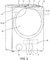
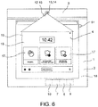
- a household appliance 1 comprises:
- the display means 13 comprise at least one video projector 14 mounted onto the household appliance 1 at the outer wall 3 and configured to visualize, by means of a light projecting process onto a display area 15 of the outer surface 4 of the housing 2.
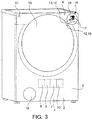
- the user command insertion means 12 comprise at least one command input sensor 16 adapted to detect a positioning and/or a movement of the user's hand at the display area 15, and generate a corresponding hand position and/or movement signal.
- the electronic control system 10 and/or the user interface 19 comprises an interpretation and association module which receives and processes the hand position and/or movement signal and generates a user command signal in dependency of which the electronic control system 10 sets the treatment program parameters and/or controls the display, by means of the video projector 14.
- the outer surface 4 in the areas of the outer surface 4 provided to implement the visualization by projecting of light, is colored and treated so as to have a higher light reflectivity with respect to an area which is not intended for visualization.
- the outer surface 4 may be either continuous or discontinuous, e.g. formed by parts of the appliance 1 connected to one another without mutual continuity of the outer surface and/or moving parts.
- the outer surface 4 in the areas of the outer surface 4 intended for implementing the visualization by projecting light, the outer surface 4 may be planar or non-planar, e.g. curved.
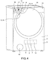
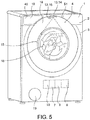
- the household appliance 1 comprises a door 18 for closing the treatment seat 5 during the execution of the treatment program and the display area 15 may extend at least also on the part of the outer surface 4 formed by the door 18.
- the treatment seat 5 is exposed directly to the outside of the household appliance 1 and forms at least part of the outer surface 4, and the display area 15 extends at least also on the part of the outer surface 4 formed by the treatment seat 5.
- the housing 2 of the appliance 1 forms an auxiliary access opening for an accessory (e.g. a detergent drawer, a bag of powder, a filter, a condensation collection drawer) of the one or more treatment devices 7, which can be closed by an auxiliary cover 19 during the execution of the treatment program, and the display area 15 can extend at least also on the part of the outer surface 4 formed by the auxiliary cover 19.
- an accessory e.g. a detergent drawer, a bag of powder, a filter, a condensation collection drawer
- the household appliance 1 comprises a single video projector 14.
- the household appliance 1 comprises a plurality of said video projectors 14 configured to project light onto one same display area 15 and/or onto a plurality of said display areas 15 which are distinct and at a distance or adjacent to each other.
- the individual video projectors 14 may be positioned on two opposite or different sides of the display area 15 and project in opposite directions or in different directions, in order to avoid the appearance of shadows when approaching of the user's hand to the display area 15.
- the video projectors 14 are configured and controlled by the electronic control system 10 so that the light wavelengths and/or the lighting frequency are compatible and do not imply destructive interferences of the projected light.
- the electronic control system 10 or the video projector 14 comprises anti-distortion means configured to calculate and generate a pre-counter-distorted image to be projected, e.g. by means of rectangle-to-trapezium pre-counter-distortion, in the opposite direction with respect to an inclined projection, e.g. from rectangle to trapezium, of the image projected onto the outer surface 4 because of the light cone of the video projector 14 and of the inclination of the projection axis with respect to the outer surface 4 in the display area 15.
- anti-distortion means configured to calculate and generate a pre-counter-distorted image to be projected, e.g. by means of rectangle-to-trapezium pre-counter-distortion, in the opposite direction with respect to an inclined projection, e.g. from rectangle to trapezium, of the image projected onto the outer surface 4 because of the light cone of the video projector 14 and of the inclination of the projection axis with respect to the outer surface 4 in the display area 15.
- the pre-counter-distortion of the image occurs in dependency of the projection cone angle and of the inclination angle of the projection axis of the video projector 14 with respect to the outer surface 4 in the display area 15, so as to compensate the projection distortion.
- the one or more video projectors 14 may comprise one or more of:
- the one or more video projectors 14 are configured as micro or pico projectors.
- the video projector 14 is positioned entirely inside the housing 2 on an inner side 20 of the outer wall 3 and performs the light projection through a window opening 21 formed in the outer wall 3.
- the window opening 21 may be a through opening or protected by a protective wall 22 which is transparent and/or which can be opened and closed by means of a protective cover 23 and/or by means of a shutter 24. This allows to conceal and protect the video projector 14.
- the video projector 14 comprises an inner part 25 located entirely inside the housing 2, i.e. on an inner side 20 of the outer wall 3, and an outer part 26 positioned completely outside the housing 2, i.e. on an outer side of the outer wall 3, wherein the volume of the inner part 25 is greater than the volume of the outer part 26. This reduces the visual impact of the video projector on the aesthetic appearance of the household appliance.
- the video projector 14 is supported in a concealable and movable manner between a rest position inside the housing 2 and a work position, in which the video projector 14 protrudes at least partially outside the housing 2.
- the position and/or orientation of the video projector 14 are adjustable, e.g. by means of the electronic control system 10.
- the position of the display area 15, or in other words the position of the display is adjustable, e.g. by means of the electronic control system 10.
- the appliance 1 or the video projector may comprise a sharpness detector and/or a focal length detector, e.g. an optical sensor, and be configured for autofocus in dependency of a sharpness or focal length signal generated by the sharpness or focal length detector.
- a sharpness detector and/or a focal length detector e.g. an optical sensor
- the control system 10 may also be configured to visualize, by means of the video projector 14, alarms or warnings directly at a component (e.g. door 18, auxiliary door 19, detergent drawer, filter holder) to which the alarm or warning relates, preferably in response to anomaly signals supplied by the anomaly detector 9 or in response to command insertion signals 16 supplied by the command insertion sensor 16, wherein the component or quantity to detect/monitor falls within the scope of detection of such detectors/sensors 9, 16.
- a component e.g. door 18, auxiliary door 19, detergent drawer, filter holder
- the warning or alarm visualization may comprise, for example, one or more of:
- the user interface 19 or the video projector 14 can comprise an audio interface 51 controlled by the electronic control system 10 to emit sound alerts (e.g. sounds, voice) in addition to the visualization operations of the video projector 14 and, possibly, so as to clarify acoustically the displayed information.
- sound alerts e.g. sounds, voice
- the features described with reference to a video projector 14 apply to at least one, some or all of the video projectors 14 in the case of a plurality of projectors 14.
- the command insertion sensor 16 comprises a proximity or touch sensor, e.g. capacitive, applied to the outer wall 3 in the display area 15.
- the touch sensor may comprise a film or a support panel on which an array of conductor(s) of the capacitors is formed, e.g. arranged according to Cartesian coordinates.
- the command insertion sensor 16 comprise one or more radar interaction sensors arranged either at or near the display area 15 and configured to recognize the position and movement of the user's hand in the immediate vicinity of the display area 15, e.g. to recognize a plurality of movements of the index finger or of the index finger and thumb of the user's hand, e.g. the so-called slider dial motions, rotary dial motions, zoom motions and pan motions.
- the command insertion sensor 16 comprises one or more optical interaction sensors arranged near the display area 15 and configured to recognize the position and movement of the user's hand in the immediate vicinity of the display area 15, e.g. to recognize a plurality of movements of the index finger or of the index finger and thumb of the user's hand, e.g. the so-called slider dial motions, rotary dial motions, zoom motions and pan motions.
- the optical interaction sensor may comprise, for example, a video camera and an interpretation software for interpreting the images recorded by the camera.
- the command insertion sensors 16 comprise one or more infrared light sources and corresponding optical sensors configured to recognize the position and movement of the user's hand in the immediate vicinity of the display area 15, e.g. to recognize a plurality of movements of the index finger or of the index finger and thumb of the user's hand, e.g. the so-called slider dial motions, rotary dial motions, zoom motions and pan motions.
- the same command insertion sensor 16 is further configured to monitor and/or verify the position and/or movements (e.g. vibrations) of moving or extractable parts (door 18, auxiliary cover 19, detergent drawer) which fall within its field or scope of detection.
- position and/or movements e.g. vibrations
- moving or extractable parts door 18, auxiliary cover 19, detergent drawer
- the command insertion means 12 may comprise an audio sensor or microphone adapted to detect audio user commands (in particular, voice commands) and to generate a corresponding voice signal.
- the electronic control system 10 :
- command insertion sensor 16 The features described with reference to a command insertion sensor 16 apply to at least one, some or all of the command insertion sensors 16 in the case of a plurality of said command insertion sensors.
- the interpretation and association module associates, e.g. by comparison of position, the detected position and/or the movement of the hand in one or more command input fields 17 visualized by means of the video projector 14 in the display area 15, and generates the user command signal in dependency of such association.
- the interpretation and association module interprets detected single positioning (touches) of the hand or finger associated with individual visualized command input fields 17 as parameter selection movements, e.g. from a plurality of different treatment parameters, and generates the user command signal in dependency of such interpretation.
- the interpretation and association module interprets detected continual movement (sliding) of the hand or finger associated with individual visualized command input fields 17 as parameter value adjustment movements (slider dial motions) and generates the user command signal in dependency of such interpretation.
- the interpretation and association module interprets detected continual and relative movements (relative sliding) of multiple detected fingers but not necessarily associated with given command input fields 17 as visualization adjustment and/or selection movements and generates the user command signal in dependency of such interpretation.
- Examples of movements and adjustment and/or visualization selection commands include zooming, panning, scrolling between multiple different screens, moving in the entire display area 15, enlarging/reducing the entire display area 15.
- the steps of interpreting the movements of the user's fingers may comprise steps of comparing characteristic parameters of the corresponding position and/or hand movement signals with reference parameters indicative of a plurality of predefined movements.
- the steps of interpreting the movements of the user's fingers may comprise steps of calculating vector paths performed by the fingers.
- the electronic control system 10 performs, by means of the video projector 14, a confirmation visualization of a user's command signal generated as a function of the aforesaid hand positioning and/or movement.
- confirmation visualization of the user's inputted command may comprise one or more of the following:
- the one or more insertion command sensors 16 may also be configured to detect and recognize a plurality of movements of the index finger or of the index finger and thumb of the user's hand, e.g. the so-called slider dial motions, rotary or arc dial motions, as well as zoom in/out motions, video pan motions, the latter not necessarily specifically referred to a visualized command input field 17, but corresponding to the gestures of the touchscreen controls known from the touchscreen tablet computers.
- the command input fields 17 may be visualized as images of one or more buttons, knobs, sliders, scales of values, or simple areas or fields, all possibly identified by a corresponding symbol, which represents e.g. a treatment parameter and/or one or more selectable values of a treatment parameter, and/or navigation command symbols for navigating between different command input menues, and/or edit or customization command symbols, such as zoom and/or brightness and/or language and/or shape of the display area 15 and/or position/displacement of the display area 15.
- the electronic control system 10 of the household appliance 1 can be connected in a communication network, e.g. via Wi-Fi or using Bluetooth, with an external electronic device 52, e.g. a smart phone or tablet computer, and adapted to be controllable, e.g. configurable or upgradeable, by means of the external electronic device 52.
- an external electronic device 52 e.g. a smart phone or tablet computer
- the electronic control system 10 can be configured, by means of the video projector 14 and the command insertion sensor 16, to mirror a user interface with a control program present on the external device 52 or on a remote server and accessible by means of the external device 52.
- the treatment devices 7 of the household appliance 1 may comprise one or more of the following:
- the treatment detectors 8 may comprise one or more of the following:
- the video projector 14 may visualize images detected by the video camera 50.
- the anomaly detectors 9 are also in signal connection with the electronic control system 10 and may comprise one or more temperature sensors, water presence sensors, smoke presence sensors, water absence sensors, position/presence sensors of movable or detachable parts of the household appliance (e.g. door 18, auxiliary door 19, detergent drawer 45, filter 46, the filter holder 47, dust bag 48).
- the electronic control system 10 may comprise one or more temperature sensors, water presence sensors, smoke presence sensors, water absence sensors, position/presence sensors of movable or detachable parts of the household appliance (e.g. door 18, auxiliary door 19, detergent drawer 45, filter 46, the filter holder 47, dust bag 48).
- the electronic control system 10 controls one or more treatment devices 7 and/or controls the display means 13 also in dependency of the anomaly signals generated by anomaly detectors 9.
- the household appliance 1 is, for example, either:
- the household products which are treated by means of the household appliance 1 may comprise one or more of either:
- the washing machine 1.1 ( figure 1-5 , 9 , 11 ) comprises a laundry basket or drum which forms the treatment seat 5 and which can be closed by means of a door 18, as well as a hydraulic system 27, a water heating system 29, a dispensing system 31 and a moving system 29a.
- the tumble dryer 1.2 ( figure 10 ) comprises a laundry basket or drum which forms the treatment seat 5 and which can be closed by a door 18, as well as a ventilation system 28, an air heating system 29, a dehumidification system 30 and an actuating/moving system 29a.
- the washing and drying machine 1.3 ( figure 11 ) comprises a laundry basket or drum which forms the treatment seat 5 and which can be closed by a door 18, as well as a hydraulic system 27, a water heating system 29, a dispensing system 31, movement system 29a, a ventilation system 28, an air heating system 29 and a dehumidification system 30.
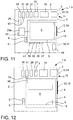
- the dishwasher 1.4 ( figure 12 ) comprises a housing cavity which forms the treatment seat 5 and which can be closed by a door 18, as well as a hydraulic system 27, a water heating system 29, a dispensing system 31 and, optionally, a dehumidification system 30.
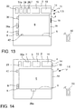
- the domestic cooking oven 1.5 ( figure 13 ) comprises a cooking cavity which forms the treatment seat 5 and which can be closed by a door 18, as well as a ventilation system 28, a heating system 29 for heating the food products, optionally a movement system 29a (e.g. for turning grilled meat), optionally a steam generator 31a for generating steam in the treatment position 6, optionally a gas burner 33 adapted to heat dishes in the treatment position 6.
- the microwave oven 1.6 ( figure 14 ) comprises a cooking cavity which forms the treatment seat 5 and which can be closed by a door 18, as well as a microwave generator 30a for generating microwaves in the treatment position 6, a movement system 29a and optionally a ventilation system 28.
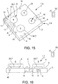
- the resistive cook top 1.8 ( figure 15 ) comprises a pot supporting structure which forms the treatment seat 5, as well as a resistive heating system 29 for heating pots or dishes in the treatment position 6.
- the inductive cook top 1.9 ( figure 15 ) comprises a pot supporting structure which forms the treatment seat 5, as well as a generator (e.g. induction coil) 32 of a variable electromagnetic field in the treatment position 6.
- a generator e.g. induction coil
- the gas cook top 1.7 ( figure 16 ) comprises a pot supporting structure which forms the treatment seat 5, as well as a gas burner 33 adapted to heat pots or dishes in the treatment position 6.
- the refrigerator 1.10 ( figure 17 ) comprises a refrigeration cavity which forms the treatment seat 5 and which can be closed by a door 18, as well as a cooling system 34 and/or freezing system adapted to cool and/or freeze domestic products in the treatment position 6 and, optionally, a ventilation system 28 and/or air circulation system for aerating the domestic products in the treatment position 6.
- the freezer 1.11 ( figure 18 ) comprises a freezing cavity which forms the treatment seat 5 and which can be closed by a door 18, as well as a freezing system 34 adapted to freeze the domestic products in the treatment position 6.
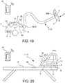
- the vacuum cleaner 1.12 ( figure 19 ) comprises a suction mouth for a furnishing surface which forms the treatment seat 5, as well as a ventilation system 28, in particular a suction system, of air from the furniture surface in the treatment position 6 and, optionally, a movement system 29a or mechanical agitation system to move the treatment seat 5.
- the ironing apparatus 1.13 ( figure 20 ) comprises a heatable plate which forms the treatment seat 5, as well as a heating system 29 for heating the heatable plate and a steam generator 31a for generating steam in the treatment position 6.
- Each of the household appliances 1, 1.1 ... 1.12 described in greater detail may selectively comprise one or more treatment detectors 8 and selectively one or more anomaly detectors 9, together with their signal connections to the electronic control system 10, described above and not repeated here for the sake of brevity.
Landscapes
- Engineering & Computer Science (AREA)
- Mechanical Engineering (AREA)
- General Engineering & Computer Science (AREA)
- Combustion & Propulsion (AREA)
- Chemical & Material Sciences (AREA)
- Textile Engineering (AREA)
- Physics & Mathematics (AREA)
- Thermal Sciences (AREA)
- Controls And Circuits For Display Device (AREA)
- User Interface Of Digital Computer (AREA)
- Electric Stoves And Ranges (AREA)
- Cookers (AREA)
- Control Of Washing Machine And Dryer (AREA)
Claims (14)
- Appareil ménager (1) comprenant :- un logement (2) avec une paroi externe (3) formant une surface externe (4) de l'appareil ménager (1),- un siège de traitement (5) formé dans le logement (2) ou au niveau de celui-ci et adapté pour loger ou supporter des produits domestiques dans une position de traitement (6),- au moins un dispositif de traitement (7) agencé à l'intérieur du logement (2) et pouvant être actionné pour effectuer un traitement au niveau de la position de traitement (6) et soumettre ledit produit domestique audit traitement,- au moins un détecteur de traitement (8) agencé au moins partiellement à l'intérieur du logement (2) et configuré pour détecter une valeur d'un paramètre de traitement du traitement effectué par le dispositif de traitement (7),- éventuellement, au moins un détecteur d'anomalie (9) agencé au moins partiellement à l'intérieur du logement (2) et configuré pour détecter une grandeur indiquant une anomalie de fonctionnement de l'appareil ménager (1),- un système de contrôle électronique (10) agencé dans le logement (2) et en connexion par signal avec le dispositif de traitement (7) et avec le détecteur de traitement (8) et configuré pour contrôler le dispositif de traitement (7) en fonction d'un programme de traitement et en fonction de la valeur détectée par le détecteur de traitement (8),- une interface utilisateur (11) en connexion par signal avec le système de contrôle électronique (10), ladite interface utilisateur (11) comprenant :- des moyens d'insertion de commande (12) pour entrer des commandes pour sélectionner les paramètres du programme de traitement et pour entrer une commande pour exécuter le programme de traitement, et- des moyens d'affichage (13) qui visualisent les paramètres sélectionnables du programme de traitement et visualisent les paramètres de traitement pendant l'exécution du programme,dans lequel les moyens d'affichage (13) comprennent au moins un projecteur vidéo (14) monté sur l'appareil ménager (1) au niveau de la paroi externe (3) et configuré pour assurer la visualisation, au moyen d'un processus de projection de lumière, sur une zone d'affichage (15) de la surface externe (4) du logement (2),
et en ce que les moyens d'insertion de commande (12) comprennent au moins un capteur d'entrée de commande (16) adapté pour détecter un mouvement de la main de l'utilisateur au niveau de la zone d'affichage (15) et pour générer un signal de mouvement de main correspondant,
dans lequel le système de contrôle électronique (10) :- traite le signal de mouvement de la main et génère un signal de commande d'utilisateur,- définit les paramètres du programme de traitement en fonction du signal de commande d'utilisateur généré,- commande l'affichage au moyen du projecteur vidéo (14) en fonction du signal de commande d'utilisateur généré,caractérisé en ce que l'au moins un capteur d'entrée de commande (16) est en outre configuré pour surveiller la position ou les mouvements de parties mobiles (18, 19) de l'appareil ménager (1) agencées dans le champ de détection de celui-ci. - Appareil ménager (1) selon la revendication 1, dans lequel le capteur d'entrée de commande (16) comprend un ou plusieurs capteurs de proximité ou tactiles appliqués sur la paroi externe (3) dans la zone d'affichage (15).
- Appareil ménager (1) selon la revendication 1, dans lequel le capteur d'entrée de commande (16) comprend un ou plusieurs capteurs d'interaction radar agencés au niveau de la zone d'affichage (15) et configurés pour reconnaître la position et le mouvement de la main de l'utilisateur au voisinage immédiat de la zone d'affichage (15).
- Appareil ménager (1) selon la revendication 1, dans lequel le capteur d'entrée de commande (16) comprend un ou plusieurs capteurs d'interaction à infrarouge agencés au niveau de la zone d'affichage (15) et configurés pour reconnaître la position et le mouvement de la main de l'utilisateur au voisinage immédiat de la zone d'affichage (15).
- Appareil ménager (1) selon la revendication 1, dans lequel le capteur d'entrée de commande (16) comprend une caméra vidéo et un logiciel pour interpréter les images enregistrées par la caméra vidéo.
- Appareil ménager (1) selon l'une quelconque des revendications précédentes, dans lequel le système de contrôle électronique (10) associe le mouvement de main détecté à la position d'un ou de plusieurs champs d'entrée de commande (17) affichés par le projecteur vidéo (14) dans la zone d'affichage (15), et génère ledit signal de commande d'utilisateur en dépendance de ladite association.
- Appareil ménager (1) selon la revendication 6, dans lequel le système de contrôle électronique (10) interprète :- des positionnements individuels du doigt qui ont été détectés et associés à des champs d'entrée de commande individuels (17) en tant que mouvements de sélection de paramètres,- des mouvements continus du doigt qui ont été détectés et associés à une série de champs d'entrée de commande (17) adjacents les uns des autres en tant que mouvements pour définir des valeurs de paramètres,- des mouvements continus et relatifs de plusieurs doigts, détectés dans la zone d'affichage (15) mais non associés à certains champs d'entrée de commande (17), en tant que mouvements pour définir l'affichage.
- Appareil ménager (1) selon la revendication 6 ou 7, dans lequel le système de contrôle électronique (10) interprète les mouvements des doigts de l'utilisateur dans la zone d'affichage (15) en comparant des paramètres caractéristiques des signaux de mouvement de main correspondants avec les paramètres de référence indicatifs pour une pluralité de mouvements prédéfinis.
- Appareil ménager (1) selon l'une des revendications 6 à 8, dans lequel le système de contrôle électronique (10) interprète les mouvements des doigts de l'utilisateur dans la zone d'affichage (15) en calculant des trajets vectoriels effectués par les doigts de l'utilisateur.
- Appareil ménager (1) selon l'une des revendications précédentes, dans lequel le système de contrôle électronique (10) effectue, au moyen du projecteur vidéo (14), une visualisation de confirmation du signal de commande d'utilisateur généré.
- Appareil ménager (1) selon la revendication 6, dans lequel les champs d'entrée de commande (17) sont affichés sous forme de :- zones délimitées et identifiées par un symbole représentant un paramètre de traitement, et/ou- une ou plusieurs valeurs sélectionnables d'un paramètre de traitement et/ou- des symboles de commande pour naviguer entre différents menus d'entrée de commande, et/ou- des symboles des commandes pour personnaliser l'affichage projeté.
- Appareil ménager (1) selon l'une quelconque des revendications précédentes, dans lequel les moyens d'insertion de commande (12) comprennent un microphone adapté pour détecter des commandes d'utilisateur vocales et pour générer un signal vocal correspondant, dans lequel le système de contrôle électronique (10) :- traite le signal vocal et génère un signal de commande d'utilisateur correspondant,- définit les paramètres de programme de traitement en fonction du signal de commande d'utilisateur généré,- commande l'affichage au moyen du projecteur vidéo (14) en fonction du signal de commande d'utilisateur généré.
- Appareil ménager (1) selon l'une quelconque des revendications précédentes, dans lequel le système de contrôle électronique (10) peut être connecté par communication sans fil à un dispositif électronique externe (52), en particulier un téléphone intelligent ou une tablette, et est adapté pour pouvoir être contrôlé et configuré au moyen du dispositif électronique externe (52).
- Appareil ménager (1) selon la revendication 13, dans lequel le système de contrôle électronique (10) est configuré pour refléter, au moyen du projecteur vidéo (14) et du capteur d'entrée de commande (16), une interface utilisateur d'un programme de contrôle présent sur le dispositif externe (52) ou sur un serveur distant et accessible au moyen du dispositif externe (52).
Applications Claiming Priority (1)
| Application Number | Priority Date | Filing Date | Title |
|---|---|---|---|
| IT102018000003723A IT201800003723A1 (it) | 2018-03-19 | 2018-03-19 | Elettrodomestico con interfaccia utente |
Publications (2)
| Publication Number | Publication Date |
|---|---|
| EP3543390A1 EP3543390A1 (fr) | 2019-09-25 |
| EP3543390B1 true EP3543390B1 (fr) | 2020-06-17 |
Family
ID=62530448
Family Applications (1)
| Application Number | Title | Priority Date | Filing Date |
|---|---|---|---|
| EP19163751.1A Active EP3543390B1 (fr) | 2018-03-19 | 2019-03-19 | Appareil ménager pourvu d'une interface utilisateur |
Country Status (4)
| Country | Link |
|---|---|
| EP (1) | EP3543390B1 (fr) |
| CN (1) | CN110285641B (fr) |
| ES (1) | ES2818051T3 (fr) |
| IT (1) | IT201800003723A1 (fr) |
Cited By (3)
| Publication number | Priority date | Publication date | Assignee | Title |
|---|---|---|---|---|
| EP4201294A1 (fr) * | 2021-12-21 | 2023-06-28 | Miele & Cie. KG | Dispositif de commande et procédé de commande d'un appareil de nettoyage et appareil de nettoyage |
| CN117269658A (zh) * | 2023-11-23 | 2023-12-22 | 江苏安世朗智能科技有限公司 | 一种精准采集各线路参数的智慧用电监测器及安装方法 |
| DE102023202694A1 (de) | 2023-03-24 | 2024-09-26 | BSH Hausgeräte GmbH | Wäschepflegegerät mit einer Projektionseinrichtung |
Families Citing this family (2)
| Publication number | Priority date | Publication date | Assignee | Title |
|---|---|---|---|---|
| DE102019209364A1 (de) * | 2019-06-27 | 2020-12-31 | BSH Hausgeräte GmbH | Wäschebearbeitungsvorrichtung |
| JP7236644B2 (ja) * | 2019-10-01 | 2023-03-10 | パナソニックIpマネジメント株式会社 | 加熱調理器 |
Family Cites Families (8)
| Publication number | Priority date | Publication date | Assignee | Title |
|---|---|---|---|---|
| US7009626B2 (en) * | 2000-04-14 | 2006-03-07 | Picsel Technologies Limited | Systems and methods for generating visual representations of graphical data and digital document processing |
| US20100231506A1 (en) * | 2004-09-07 | 2010-09-16 | Timothy Pryor | Control of appliances, kitchen and home |
| CN201535891U (zh) * | 2009-08-03 | 2010-07-28 | 程宇航 | 一种计算机图形用户界面的输入设备 |
| US8723934B2 (en) * | 2011-06-27 | 2014-05-13 | General Electric Company | Projected user interface onto the surface of an appliance |
| CN108469899B (zh) * | 2012-03-13 | 2021-08-10 | 视力移动技术有限公司 | 识别可穿戴显示装置的观察空间中的瞄准点或区域的方法 |
| CN102707896B (zh) * | 2012-06-04 | 2014-12-17 | 天津三星电子有限公司 | 一种显示终端操作控制方法及其显示终端 |
| DE102012106181A1 (de) * | 2012-07-10 | 2014-01-16 | Miele & Cie. Kg | Haushaltgerät mit einer Anzeigevorrichtung und Verfahren zum Anzeigen von Geräteinformationen eines Haushaltgeräts |
| CN106647303B (zh) * | 2016-12-23 | 2019-10-01 | 重庆墨希科技有限公司 | 一种智能家居控制方法、系统以及一种智能手环 |
-
2018
- 2018-03-19 IT IT102018000003723A patent/IT201800003723A1/it unknown
-
2019
- 2019-03-19 EP EP19163751.1A patent/EP3543390B1/fr active Active
- 2019-03-19 CN CN201910209953.1A patent/CN110285641B/zh active Active
- 2019-03-19 ES ES19163751T patent/ES2818051T3/es active Active
Non-Patent Citations (1)
| Title |
|---|
| None * |
Cited By (5)
| Publication number | Priority date | Publication date | Assignee | Title |
|---|---|---|---|---|
| EP4201294A1 (fr) * | 2021-12-21 | 2023-06-28 | Miele & Cie. KG | Dispositif de commande et procédé de commande d'un appareil de nettoyage et appareil de nettoyage |
| BE1030060B1 (de) * | 2021-12-21 | 2023-07-17 | Miele & Cie | Bedienvorrichtung und Verfahren zum Bedienen eines Reinigungsgeräts und Reinigungsgerät |
| DE102023202694A1 (de) | 2023-03-24 | 2024-09-26 | BSH Hausgeräte GmbH | Wäschepflegegerät mit einer Projektionseinrichtung |
| CN117269658A (zh) * | 2023-11-23 | 2023-12-22 | 江苏安世朗智能科技有限公司 | 一种精准采集各线路参数的智慧用电监测器及安装方法 |
| CN117269658B (zh) * | 2023-11-23 | 2024-02-02 | 江苏安世朗智能科技有限公司 | 一种精准采集各线路参数的智慧用电监测器及安装方法 |
Also Published As
| Publication number | Publication date |
|---|---|
| ES2818051T3 (es) | 2021-04-09 |
| IT201800003723A1 (it) | 2019-09-19 |
| CN110285641B (zh) | 2021-09-14 |
| CN110285641A (zh) | 2019-09-27 |
| EP3543390A1 (fr) | 2019-09-25 |
Similar Documents
| Publication | Publication Date | Title |
|---|---|---|
| EP3543390B1 (fr) | Appareil ménager pourvu d'une interface utilisateur | |
| EP3543990A1 (fr) | Appareil ménager pourvu d'une interface utilisateur | |
| US10222964B2 (en) | Operation device and operation method | |
| CN108475177B (zh) | 用于电器的拖动设置用户界面 | |
| US9261280B2 (en) | User interface and cooking oven provided with such user interface | |
| EP2259169B1 (fr) | Appareil ménager avec interface virtuelle de données. | |
| CN108474560A (zh) | 终端、与其通信的烹饪器具以及控制烹饪器具的方法 | |
| CN109963975B (zh) | 具有投影装置的家用器具及其运行方法 | |
| US11182123B2 (en) | User-interface system for a laundry appliance | |
| EP2979036A2 (fr) | Interface utilisateur pour produits blancs et capteurs de proximité à canaux multiples associés | |
| RU2787682C2 (ru) | Бытовой электроприбор с пользовательским интерфейсом | |
| KR101920430B1 (ko) | 조리기 및 그 입력 제어방법 | |
| RU2787761C2 (ru) | Бытовой электроприбор с пользовательским интерфейсом | |
| EP3885483A1 (fr) | Machine à laver dotée d'une interface utilisateur | |
| JP2021167698A (ja) | 加熱調理器 | |
| TR201921442A1 (tr) | Ankastre setlerde kullanilan bi̇r dokunmati̇k projeksi̇yon ve çalişma yöntemi̇ | |
| JP2020129462A (ja) | 誘導加熱調理器 | |
| JP2016015235A (ja) | 誘導加熱調理器 |
Legal Events
| Date | Code | Title | Description |
|---|---|---|---|
| PUAI | Public reference made under article 153(3) epc to a published international application that has entered the european phase |
Free format text: ORIGINAL CODE: 0009012 |
|
| STAA | Information on the status of an ep patent application or granted ep patent |
Free format text: STATUS: REQUEST FOR EXAMINATION WAS MADE |
|
| 17P | Request for examination filed |
Effective date: 20190801 |
|
| AK | Designated contracting states |
Kind code of ref document: A1 Designated state(s): AL AT BE BG CH CY CZ DE DK EE ES FI FR GB GR HR HU IE IS IT LI LT LU LV MC MK MT NL NO PL PT RO RS SE SI SK SM TR |
|
| AX | Request for extension of the european patent |
Extension state: BA ME |
|
| RIC1 | Information provided on ipc code assigned before grant |
Ipc: F25D 29/00 20060101ALN20191218BHEP Ipc: F24C 7/08 20060101ALN20191218BHEP Ipc: D06F 58/28 20060101ALN20191218BHEP Ipc: D06F 39/00 20060101AFI20191218BHEP |
|
| GRAP | Despatch of communication of intention to grant a patent |
Free format text: ORIGINAL CODE: EPIDOSNIGR1 |
|
| STAA | Information on the status of an ep patent application or granted ep patent |
Free format text: STATUS: GRANT OF PATENT IS INTENDED |
|
| INTG | Intention to grant announced |
Effective date: 20200204 |
|
| RIC1 | Information provided on ipc code assigned before grant |
Ipc: D06F 39/00 20200101AFI20200130BHEP Ipc: F24C 7/08 20060101ALI20200130BHEP Ipc: F25D 29/00 20060101ALI20200130BHEP Ipc: D06F 58/30 20200101ALI20200130BHEP |
|
| GRAS | Grant fee paid |
Free format text: ORIGINAL CODE: EPIDOSNIGR3 |
|
| GRAA | (expected) grant |
Free format text: ORIGINAL CODE: 0009210 |
|
| STAA | Information on the status of an ep patent application or granted ep patent |
Free format text: STATUS: THE PATENT HAS BEEN GRANTED |
|
| AK | Designated contracting states |
Kind code of ref document: B1 Designated state(s): AL AT BE BG CH CY CZ DE DK EE ES FI FR GB GR HR HU IE IS IT LI LT LU LV MC MK MT NL NO PL PT RO RS SE SI SK SM TR |
|
| REG | Reference to a national code |
Ref country code: GB Ref legal event code: FG4D |
|
| REG | Reference to a national code |
Ref country code: CH Ref legal event code: EP |
|
| REG | Reference to a national code |
Ref country code: DE Ref legal event code: R096 Ref document number: 602019000187 Country of ref document: DE |
|
| REG | Reference to a national code |
Ref country code: IE Ref legal event code: FG4D |
|
| REG | Reference to a national code |
Ref country code: AT Ref legal event code: REF Ref document number: 1281421 Country of ref document: AT Kind code of ref document: T Effective date: 20200715 |
|
| PG25 | Lapsed in a contracting state [announced via postgrant information from national office to epo] |
Ref country code: FI Free format text: LAPSE BECAUSE OF FAILURE TO SUBMIT A TRANSLATION OF THE DESCRIPTION OR TO PAY THE FEE WITHIN THE PRESCRIBED TIME-LIMIT Effective date: 20200617 Ref country code: GR Free format text: LAPSE BECAUSE OF FAILURE TO SUBMIT A TRANSLATION OF THE DESCRIPTION OR TO PAY THE FEE WITHIN THE PRESCRIBED TIME-LIMIT Effective date: 20200918 Ref country code: LT Free format text: LAPSE BECAUSE OF FAILURE TO SUBMIT A TRANSLATION OF THE DESCRIPTION OR TO PAY THE FEE WITHIN THE PRESCRIBED TIME-LIMIT Effective date: 20200617 Ref country code: SE Free format text: LAPSE BECAUSE OF FAILURE TO SUBMIT A TRANSLATION OF THE DESCRIPTION OR TO PAY THE FEE WITHIN THE PRESCRIBED TIME-LIMIT Effective date: 20200617 Ref country code: NO Free format text: LAPSE BECAUSE OF FAILURE TO SUBMIT A TRANSLATION OF THE DESCRIPTION OR TO PAY THE FEE WITHIN THE PRESCRIBED TIME-LIMIT Effective date: 20200917 |
|
| REG | Reference to a national code |
Ref country code: LT Ref legal event code: MG4D |
|
| REG | Reference to a national code |
Ref country code: NL Ref legal event code: MP Effective date: 20200617 |
|
| PG25 | Lapsed in a contracting state [announced via postgrant information from national office to epo] |
Ref country code: HR Free format text: LAPSE BECAUSE OF FAILURE TO SUBMIT A TRANSLATION OF THE DESCRIPTION OR TO PAY THE FEE WITHIN THE PRESCRIBED TIME-LIMIT Effective date: 20200617 Ref country code: RS Free format text: LAPSE BECAUSE OF FAILURE TO SUBMIT A TRANSLATION OF THE DESCRIPTION OR TO PAY THE FEE WITHIN THE PRESCRIBED TIME-LIMIT Effective date: 20200617 Ref country code: BG Free format text: LAPSE BECAUSE OF FAILURE TO SUBMIT A TRANSLATION OF THE DESCRIPTION OR TO PAY THE FEE WITHIN THE PRESCRIBED TIME-LIMIT Effective date: 20200917 Ref country code: LV Free format text: LAPSE BECAUSE OF FAILURE TO SUBMIT A TRANSLATION OF THE DESCRIPTION OR TO PAY THE FEE WITHIN THE PRESCRIBED TIME-LIMIT Effective date: 20200617 |
|
| REG | Reference to a national code |
Ref country code: AT Ref legal event code: MK05 Ref document number: 1281421 Country of ref document: AT Kind code of ref document: T Effective date: 20200617 |
|
| PG25 | Lapsed in a contracting state [announced via postgrant information from national office to epo] |
Ref country code: NL Free format text: LAPSE BECAUSE OF FAILURE TO SUBMIT A TRANSLATION OF THE DESCRIPTION OR TO PAY THE FEE WITHIN THE PRESCRIBED TIME-LIMIT Effective date: 20200617 Ref country code: AL Free format text: LAPSE BECAUSE OF FAILURE TO SUBMIT A TRANSLATION OF THE DESCRIPTION OR TO PAY THE FEE WITHIN THE PRESCRIBED TIME-LIMIT Effective date: 20200617 |
|
| PG25 | Lapsed in a contracting state [announced via postgrant information from national office to epo] |
Ref country code: EE Free format text: LAPSE BECAUSE OF FAILURE TO SUBMIT A TRANSLATION OF THE DESCRIPTION OR TO PAY THE FEE WITHIN THE PRESCRIBED TIME-LIMIT Effective date: 20200617 Ref country code: SM Free format text: LAPSE BECAUSE OF FAILURE TO SUBMIT A TRANSLATION OF THE DESCRIPTION OR TO PAY THE FEE WITHIN THE PRESCRIBED TIME-LIMIT Effective date: 20200617 Ref country code: AT Free format text: LAPSE BECAUSE OF FAILURE TO SUBMIT A TRANSLATION OF THE DESCRIPTION OR TO PAY THE FEE WITHIN THE PRESCRIBED TIME-LIMIT Effective date: 20200617 Ref country code: RO Free format text: LAPSE BECAUSE OF FAILURE TO SUBMIT A TRANSLATION OF THE DESCRIPTION OR TO PAY THE FEE WITHIN THE PRESCRIBED TIME-LIMIT Effective date: 20200617 Ref country code: CZ Free format text: LAPSE BECAUSE OF FAILURE TO SUBMIT A TRANSLATION OF THE DESCRIPTION OR TO PAY THE FEE WITHIN THE PRESCRIBED TIME-LIMIT Effective date: 20200617 Ref country code: PT Free format text: LAPSE BECAUSE OF FAILURE TO SUBMIT A TRANSLATION OF THE DESCRIPTION OR TO PAY THE FEE WITHIN THE PRESCRIBED TIME-LIMIT Effective date: 20201019 |
|
| PG25 | Lapsed in a contracting state [announced via postgrant information from national office to epo] |
Ref country code: PL Free format text: LAPSE BECAUSE OF FAILURE TO SUBMIT A TRANSLATION OF THE DESCRIPTION OR TO PAY THE FEE WITHIN THE PRESCRIBED TIME-LIMIT Effective date: 20200617 Ref country code: SK Free format text: LAPSE BECAUSE OF FAILURE TO SUBMIT A TRANSLATION OF THE DESCRIPTION OR TO PAY THE FEE WITHIN THE PRESCRIBED TIME-LIMIT Effective date: 20200617 Ref country code: IS Free format text: LAPSE BECAUSE OF FAILURE TO SUBMIT A TRANSLATION OF THE DESCRIPTION OR TO PAY THE FEE WITHIN THE PRESCRIBED TIME-LIMIT Effective date: 20201017 |
|
| REG | Reference to a national code |
Ref country code: DE Ref legal event code: R097 Ref document number: 602019000187 Country of ref document: DE |
|
| REG | Reference to a national code |
Ref country code: ES Ref legal event code: FG2A Ref document number: 2818051 Country of ref document: ES Kind code of ref document: T3 Effective date: 20210409 |
|
| PLBE | No opposition filed within time limit |
Free format text: ORIGINAL CODE: 0009261 |
|
| STAA | Information on the status of an ep patent application or granted ep patent |
Free format text: STATUS: NO OPPOSITION FILED WITHIN TIME LIMIT |
|
| PG25 | Lapsed in a contracting state [announced via postgrant information from national office to epo] |
Ref country code: DK Free format text: LAPSE BECAUSE OF FAILURE TO SUBMIT A TRANSLATION OF THE DESCRIPTION OR TO PAY THE FEE WITHIN THE PRESCRIBED TIME-LIMIT Effective date: 20200617 |
|
| 26N | No opposition filed |
Effective date: 20210318 |
|
| PG25 | Lapsed in a contracting state [announced via postgrant information from national office to epo] |
Ref country code: MC Free format text: LAPSE BECAUSE OF FAILURE TO SUBMIT A TRANSLATION OF THE DESCRIPTION OR TO PAY THE FEE WITHIN THE PRESCRIBED TIME-LIMIT Effective date: 20200617 |
|
| REG | Reference to a national code |
Ref country code: BE Ref legal event code: MM Effective date: 20210331 |
|
| PG25 | Lapsed in a contracting state [announced via postgrant information from national office to epo] |
Ref country code: LU Free format text: LAPSE BECAUSE OF NON-PAYMENT OF DUE FEES Effective date: 20210319 Ref country code: IE Free format text: LAPSE BECAUSE OF NON-PAYMENT OF DUE FEES Effective date: 20210319 |
|
| PG25 | Lapsed in a contracting state [announced via postgrant information from national office to epo] |
Ref country code: BE Free format text: LAPSE BECAUSE OF NON-PAYMENT OF DUE FEES Effective date: 20210331 |
|
| REG | Reference to a national code |
Ref country code: CH Ref legal event code: PL |
|
| PG25 | Lapsed in a contracting state [announced via postgrant information from national office to epo] |
Ref country code: LI Free format text: LAPSE BECAUSE OF NON-PAYMENT OF DUE FEES Effective date: 20220331 Ref country code: CH Free format text: LAPSE BECAUSE OF NON-PAYMENT OF DUE FEES Effective date: 20220331 |
|
| PG25 | Lapsed in a contracting state [announced via postgrant information from national office to epo] |
Ref country code: CY Free format text: LAPSE BECAUSE OF FAILURE TO SUBMIT A TRANSLATION OF THE DESCRIPTION OR TO PAY THE FEE WITHIN THE PRESCRIBED TIME-LIMIT Effective date: 20200617 |
|
| PG25 | Lapsed in a contracting state [announced via postgrant information from national office to epo] |
Ref country code: HU Free format text: LAPSE BECAUSE OF FAILURE TO SUBMIT A TRANSLATION OF THE DESCRIPTION OR TO PAY THE FEE WITHIN THE PRESCRIBED TIME-LIMIT; INVALID AB INITIO Effective date: 20190319 |
|
| PG25 | Lapsed in a contracting state [announced via postgrant information from national office to epo] |
Ref country code: SI Free format text: LAPSE BECAUSE OF FAILURE TO SUBMIT A TRANSLATION OF THE DESCRIPTION OR TO PAY THE FEE WITHIN THE PRESCRIBED TIME-LIMIT Effective date: 20200617 |
|
| PG25 | Lapsed in a contracting state [announced via postgrant information from national office to epo] |
Ref country code: MK Free format text: LAPSE BECAUSE OF FAILURE TO SUBMIT A TRANSLATION OF THE DESCRIPTION OR TO PAY THE FEE WITHIN THE PRESCRIBED TIME-LIMIT Effective date: 20200617 |
|
| PGFP | Annual fee paid to national office [announced via postgrant information from national office to epo] |
Ref country code: DE Payment date: 20240320 Year of fee payment: 6 Ref country code: GB Payment date: 20240320 Year of fee payment: 6 |
|
| PGFP | Annual fee paid to national office [announced via postgrant information from national office to epo] |
Ref country code: TR Payment date: 20240311 Year of fee payment: 6 Ref country code: IT Payment date: 20240124 Year of fee payment: 6 Ref country code: FR Payment date: 20240229 Year of fee payment: 6 |
|
| PGFP | Annual fee paid to national office [announced via postgrant information from national office to epo] |
Ref country code: ES Payment date: 20240401 Year of fee payment: 6 |