EP3543073B1 - Sitzgurtsteuerungsvorrichtung - Google Patents
Sitzgurtsteuerungsvorrichtung Download PDFInfo
- Publication number
- EP3543073B1 EP3543073B1 EP19164043.2A EP19164043A EP3543073B1 EP 3543073 B1 EP3543073 B1 EP 3543073B1 EP 19164043 A EP19164043 A EP 19164043A EP 3543073 B1 EP3543073 B1 EP 3543073B1
- Authority
- EP
- European Patent Office
- Prior art keywords
- section
- collision
- force limiter
- seatbelt
- threshold
- Prior art date
- Legal status (The legal status is an assumption and is not a legal conclusion. Google has not performed a legal analysis and makes no representation as to the accuracy of the status listed.)
- Active
Links
Images





Classifications
-
- B—PERFORMING OPERATIONS; TRANSPORTING
- B60—VEHICLES IN GENERAL
- B60R—VEHICLES, VEHICLE FITTINGS, OR VEHICLE PARTS, NOT OTHERWISE PROVIDED FOR
- B60R22/00—Safety belts or body harnesses in vehicles
- B60R22/34—Belt retractors, e.g. reels
- B60R22/46—Reels with means to tension the belt in an emergency by forced winding up
- B60R22/4676—Reels with means to tension the belt in an emergency by forced winding up comprising energy-absorbing means operating between belt reel and retractor frame
-
- B—PERFORMING OPERATIONS; TRANSPORTING
- B60—VEHICLES IN GENERAL
- B60R—VEHICLES, VEHICLE FITTINGS, OR VEHICLE PARTS, NOT OTHERWISE PROVIDED FOR
- B60R21/00—Arrangements or fittings on vehicles for protecting or preventing injuries to occupants or pedestrians in case of accidents or other traffic risks
- B60R21/01—Electrical circuits for triggering passive safety arrangements, e.g. airbags, safety belt tighteners, in case of vehicle accidents or impending vehicle accidents
- B60R21/013—Electrical circuits for triggering passive safety arrangements, e.g. airbags, safety belt tighteners, in case of vehicle accidents or impending vehicle accidents including means for detecting collisions, impending collisions or roll-over
- B60R21/0132—Electrical circuits for triggering passive safety arrangements, e.g. airbags, safety belt tighteners, in case of vehicle accidents or impending vehicle accidents including means for detecting collisions, impending collisions or roll-over responsive to vehicle motion parameters, e.g. to vehicle longitudinal or transversal deceleration or speed value
-
- B—PERFORMING OPERATIONS; TRANSPORTING
- B60—VEHICLES IN GENERAL
- B60R—VEHICLES, VEHICLE FITTINGS, OR VEHICLE PARTS, NOT OTHERWISE PROVIDED FOR
- B60R22/00—Safety belts or body harnesses in vehicles
- B60R22/34—Belt retractors, e.g. reels
- B60R22/44—Belt retractors, e.g. reels with means for reducing belt tension during use under normal conditions
-
- B—PERFORMING OPERATIONS; TRANSPORTING
- B60—VEHICLES IN GENERAL
- B60R—VEHICLES, VEHICLE FITTINGS, OR VEHICLE PARTS, NOT OTHERWISE PROVIDED FOR
- B60R22/00—Safety belts or body harnesses in vehicles
- B60R22/34—Belt retractors, e.g. reels
- B60R22/46—Reels with means to tension the belt in an emergency by forced winding up
-
- B—PERFORMING OPERATIONS; TRANSPORTING
- B60—VEHICLES IN GENERAL
- B60R—VEHICLES, VEHICLE FITTINGS, OR VEHICLE PARTS, NOT OTHERWISE PROVIDED FOR
- B60R22/00—Safety belts or body harnesses in vehicles
- B60R22/48—Control systems, alarms, or interlock systems, for the correct application of the belt or harness
-
- B—PERFORMING OPERATIONS; TRANSPORTING
- B60—VEHICLES IN GENERAL
- B60R—VEHICLES, VEHICLE FITTINGS, OR VEHICLE PARTS, NOT OTHERWISE PROVIDED FOR
- B60R21/00—Arrangements or fittings on vehicles for protecting or preventing injuries to occupants or pedestrians in case of accidents or other traffic risks
- B60R21/01—Electrical circuits for triggering passive safety arrangements, e.g. airbags, safety belt tighteners, in case of vehicle accidents or impending vehicle accidents
- B60R2021/01204—Actuation parameters of safety arrangents
- B60R2021/01252—Devices other than bags
- B60R2021/01265—Seat belts
- B60R2021/01272—Belt tensioners
-
- B—PERFORMING OPERATIONS; TRANSPORTING
- B60—VEHICLES IN GENERAL
- B60R—VEHICLES, VEHICLE FITTINGS, OR VEHICLE PARTS, NOT OTHERWISE PROVIDED FOR
- B60R21/00—Arrangements or fittings on vehicles for protecting or preventing injuries to occupants or pedestrians in case of accidents or other traffic risks
- B60R21/01—Electrical circuits for triggering passive safety arrangements, e.g. airbags, safety belt tighteners, in case of vehicle accidents or impending vehicle accidents
- B60R2021/01204—Actuation parameters of safety arrangents
- B60R2021/01252—Devices other than bags
- B60R2021/01265—Seat belts
- B60R2021/01279—Load limiters
-
- B—PERFORMING OPERATIONS; TRANSPORTING
- B60—VEHICLES IN GENERAL
- B60R—VEHICLES, VEHICLE FITTINGS, OR VEHICLE PARTS, NOT OTHERWISE PROVIDED FOR
- B60R21/00—Arrangements or fittings on vehicles for protecting or preventing injuries to occupants or pedestrians in case of accidents or other traffic risks
- B60R21/01—Electrical circuits for triggering passive safety arrangements, e.g. airbags, safety belt tighteners, in case of vehicle accidents or impending vehicle accidents
- B60R21/013—Electrical circuits for triggering passive safety arrangements, e.g. airbags, safety belt tighteners, in case of vehicle accidents or impending vehicle accidents including means for detecting collisions, impending collisions or roll-over
- B60R21/0132—Electrical circuits for triggering passive safety arrangements, e.g. airbags, safety belt tighteners, in case of vehicle accidents or impending vehicle accidents including means for detecting collisions, impending collisions or roll-over responsive to vehicle motion parameters, e.g. to vehicle longitudinal or transversal deceleration or speed value
- B60R2021/01322—Electrical circuits for triggering passive safety arrangements, e.g. airbags, safety belt tighteners, in case of vehicle accidents or impending vehicle accidents including means for detecting collisions, impending collisions or roll-over responsive to vehicle motion parameters, e.g. to vehicle longitudinal or transversal deceleration or speed value comprising variable thresholds, e.g. depending from other collision parameters
-
- B—PERFORMING OPERATIONS; TRANSPORTING
- B60—VEHICLES IN GENERAL
- B60R—VEHICLES, VEHICLE FITTINGS, OR VEHICLE PARTS, NOT OTHERWISE PROVIDED FOR
- B60R22/00—Safety belts or body harnesses in vehicles
- B60R22/34—Belt retractors, e.g. reels
- B60R22/46—Reels with means to tension the belt in an emergency by forced winding up
- B60R2022/4685—Reels with means to tension the belt in an emergency by forced winding up with means to adjust or regulate the tensioning force in relation to external parameters
-
- B—PERFORMING OPERATIONS; TRANSPORTING
- B60—VEHICLES IN GENERAL
- B60R—VEHICLES, VEHICLE FITTINGS, OR VEHICLE PARTS, NOT OTHERWISE PROVIDED FOR
- B60R21/00—Arrangements or fittings on vehicles for protecting or preventing injuries to occupants or pedestrians in case of accidents or other traffic risks
- B60R21/01—Electrical circuits for triggering passive safety arrangements, e.g. airbags, safety belt tighteners, in case of vehicle accidents or impending vehicle accidents
- B60R21/015—Electrical circuits for triggering passive safety arrangements, e.g. airbags, safety belt tighteners, in case of vehicle accidents or impending vehicle accidents including means for detecting the presence or position of passengers, passenger seats or child seats, and the related safety parameters therefor, e.g. speed or timing of airbag inflation in relation to occupant position or seat belt use
- B60R21/01558—Electrical circuits for triggering passive safety arrangements, e.g. airbags, safety belt tighteners, in case of vehicle accidents or impending vehicle accidents including means for detecting the presence or position of passengers, passenger seats or child seats, and the related safety parameters therefor, e.g. speed or timing of airbag inflation in relation to occupant position or seat belt use monitoring crash strength
Definitions
- the present disclosure relates to a seatbelt control device.
- JP-A Japanese Patent Application Laid-Open
- JP-A No. 2009-190594 proposes a technology in which a load setting of a force limiter mechanism is switched according to whether or not deceleration of a vehicle exceeds a second threshold within a time period A for identifying a collision, the time period A running from the start of activation of a pre-tensioner mechanism when the vehicle deceleration has exceeded a first threshold.
- the force limiter mechanism is set to a high load, in a case in which the vehicle deceleration exceeds the second threshold within the time period A, and the force limiter mechanism is set to a low load after the time period A has elapsed, in a case in which the vehicle deceleration does not exceed the second threshold within the time period A.
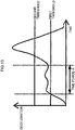
- a change in deceleration over time when a vehicle collides with an object varies according to the hardness of the colliding object, the manner of collision, and so on. For example, in a case in which a colliding object has a soft leading end followed by a hard portion, as illustrated in Fig. 13 as an example, a change is exhibited in which the soft leading end deforms during an initial stage of the collision, resulting in a small amount of deceleration, after which the hard portion subsequently strikes the vehicle and deceleration increases.
- An example of an object with a soft leading end followed by a hard portion is a front section of a vehicle, which has a soft bumper at a front end, and a hard engine disposed behind the bumper.
- a front-end collision between vehicles is a typical example of a collision that would exhibit a change in deceleration over time such as that illustrated in Fig. 13 .
- collisions exhibiting a change in deceleration over time are not limited to cases in which the vehicle collides with an object with a soft leading end and followed by a hard portion.
- a hard, narrow object such as a utility pole collides near to a vehicle width direction central portion of a front section of a vehicle
- a change is exhibited in which the vehicle bumper deforms in the initial stage of the collision, resulting in a small amount of deceleration, following which the colliding object strikes the engine and deceleration increases.
- the overall collision energy of the collision is relatively high (an integral value of the change in deceleration is relatively large), and so it would be appropriate to set the force limiter mechanism to a high load.
- the present disclosure provides a seatbelt control device that may appropriately control the load of a force limiter section, in a case in which a collision with a low impact intensity in an initial stage of the collision has occurred.
- a first aspect of the present disclosure is a seatbelt control device including: a pre-tensioner section configured to retract a seatbelt to increase tension of the seatbelt; a force limiter section configured to change a magnitude of a load at which to start reducing tension of the seatbelt retracted by the pre-tensioner section; and a controller configured to activate the pre-tensioner section in a case in which a physical quantity relating to a magnitude of a collision detected by a first detection section for detecting the physical quantity exceeds a first threshold, or in a case in which a collision has been predicted by a collision prediction section, the controller controlling the load of the force limiter section in a case in which, within a predetermined period after activation of the pre-tensioner section, the physical quantity detected by the first detection section has exceeded a second threshold set according to a collision velocity detected by a second detection section, so as to be a greater load than the load of the force limiter section in a case in which the physical quantity has not exceeded the second threshold within the predetermined
- the pre-tensioner section is activated in a case in which the physical quantity relating to the magnitude of a collision exceeds the first threshold, or in a case in which a collision has been predicted.
- the load at which the force limiter section starts reducing tension of the seatbelt retracted by the pre-tensioner section is controlled so as to be a greater load than in a case in which the physical quantity has not exceeded the second threshold within the predetermined period.
- the second threshold is set according to the collision velocity detected by the second detection section.
- the physical quantity can easily exceed the second threshold value within the predetermined period, even in a collision with low impact intensity during the initial collision stage.
- the load of the force limiter section is controlled so as to be a large load.
- the physical quantity cannot exceed the second threshold value so easily within the predetermined period.
- the load of the force limiter section is controlled so as to be a small load. Accordingly, the first aspect of the present disclosure may appropriately control the load of the force limiter section in collisions with low impact intensity during the initial collision stage.
- the controller may set the second threshold applied in a case in which the collision velocity has exceeded a predetermined value, to a value no greater than the second threshold applied in a case in which the collision velocity has not exceeded the predetermined value.
- the second threshold applied in a case in which the collision velocity has exceeded the predetermined value is set to a value no greater than the second threshold applied in a case in which the collision velocity has not exceeded the predetermined value. Accordingly, in a case in which the collision velocity has exceeded the predetermined value, and the collision is anticipated to have a large collision energy overall, the physical quantity can exceed the second threshold more easily within the predetermined period due to setting the second threshold to a lower value. Accordingly, the second aspect of the present disclosure may even more appropriately control the load of the force limiter section in collisions with low impact intensity during the initial collision stage.
- the second detection section may be at least one of a radar or a camera.
- the first detection section may detect deceleration as the physical quantity; and the controller, may sets as the second threshold, a threshold for an integral value of the deceleration detected by the first detection section according to the collision velocity, and determines whether or not the integral value of the deceleration has exceeded the set second threshold within a predetermined period after the pre-tensioner section has been activated.
- a seatbelt control device of the present disclosure may appropriately control the load of the force limiter section in a case in which a collision with a low impact intensity in an initial stage of the collision has occurred.
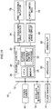
- an onboard system 10 includes a bus 12.
- Plural sensor units and plural electronic control units that perform different control to each other are respectively connected to the bus 12.
- Fig. 1 only illustrates part of the onboard system 10.
- Each individual Electronic Control Unit (hereafter referred to as ECU) is a control unit including a CPU, memory, and a non-volatile storage section.
- the plural sensor units connected to the bus 12 include a floor sensor 14, satellite sensors 16, and a radar device 18.
- the plural ECUs connected to the bus 12 include an airbag ECU 20 and a seatbelt control ECU 24.
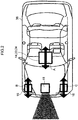
- the floor sensor 14 is disposed inside a vehicle cabin of a vehicle 38 together with the airbag ECU 20 and the seatbelt control ECU 24.
- the floor sensor 14 detects front-rear direction acceleration (deceleration G) of the vehicle 38 inside the vehicle cabin of the vehicle 38, as illustrated by the arrow A in Fig. 2 .
- the satellite sensors 16 are respectively disposed on the left and right of the vehicle 38, close to a front end section.
- the satellite sensors 16 detect front-rear direction acceleration (deceleration Gs) on the left and right of the vehicle 38 close to the front end section of the vehicle 38, as illustrated by the arrows B, C in Fig. 2 .
- the radar device 18 includes plural radar devices having different detection ranges to each other.
- the radar device 18 detects objects such as pedestrians and other vehicles present within a detection range in front of the vehicle 38 (illustrated by hatching in Fig. 2 ) as point information, and acquires the position and speed of detected objects relative to the vehicle 38.
- a processor that processes detection results for objects in the vicinity is inbuilt in the radar device 18. Based on changes in the relative position, relative speed, and so on of each object included in plural recent detection results, the processor eliminates noise, roadside objects such as guard rails, and the like from monitoring targets, and tracks designated objects, such as pedestrians and other vehicles, as monitoring targets.
- the radar device 18 outputs information such as the relative position and relative speed of each monitoring target object.
- the airbag actuator 22 configures an airbag device together with the airbag ECU 20 and is connected to the airbag ECU 20.
- actuator is hereafter abbreviated to "ACT”.
- ACT airbag ACT
- the seatbelt control ECU 24 includes a CPU 26, memory 28, and a non-volatile storage section 30.
- a seatbelt control program 32 is stored in the storage section 30.
- the seatbelt control ECU 24 performs seatbelt control processing, described later, by reading the seatbelt control program 32 from the storage section 30 and expanding the seatbelt control program 32 in the memory 28, and executing the seatbelt control program 32 expanded in the memory 28 using the CPU 26.
- a pre-tensioner inflator 78 is connected to the seatbelt control ECU 24 via a pre-tensioner drive circuit 34.
- a force limiter Micro Gas Generator (MGG) 76 is also connected to the seatbelt control ECU 24 via a force limiter drive circuit 36.
- the seatbelt control ECU 24 controls ignition of the pre-tensioner inflator 78 through the pre-tensioner drive circuit 34 based on information input from the floor sensor 14 and the satellite sensors 16.
- the seatbelt control ECU 24 also controls ignition of the force limiter MGG 76 through the force limiter drive circuit 36 based on information input from the floor sensor 14 and the radar device 18.
- the floor sensor 14 is an example of a first detection section
- the radar device 18 is an example of a second detection section
- the seatbelt control ECU 24, the pre-tensioner drive circuit 34, and the force limiter drive circuit 36 configure an example of a controller.
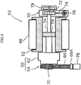
- a seatbelt retractor device 50 includes a spool 52 that retracts a seatbelt 66.
- a central portion of the spool 52 is hollow, and a torsion bar 54 is provided in the hollow portion.
- the torsion bar 54 is coupled to the spool 52 through a coupling member 56 disposed close to an axial direction center portion of the spool 52, and functions as a rotation shaft of the spool 52.
- the diameter of the torsion bar 54 is different on either side of the coupling member 56.
- the torsion bar 54 has a larger diameter on the side of a pre-tensioner section 58 than on the side of a force limiter section 60, described later.
- the force limiter section 60 side and the pre-tensioner section 58 side of the torsion bar 54 may be configured by a single unit, or the torsion bar 54 may have a structure in which the force limiter section 60 side and the pre-tensioner section 58 side of the torsion bar 54 are configured separately and coupled together by the coupling member 56.
- the pre-tensioner section 58 is provided at one end of the torsion bar 54, and the force limiter section 60 is provided at the other end of the torsion bar 54.
- the pre-tensioner section 58 includes a belt lock mechanism 62 and a pre-tensioner mechanism 64.
- the belt lock mechanism 62 locks rotation of the spool 52 when a predetermined load is applied.
- Various known configurations may be applied as the belt lock mechanism 62, and so detailed explanation thereof is omitted.
- the pre-tensioner mechanism 64 includes the pre-tensioner inflator 78, a piston rack 68, and a pinion gear 70.
- the pre-tensioner inflator 78 is ignited and gas is generated in the pre-tensioner section 58, a piston 68A of the piston rack 68 is pushed outward, and the spool 52 is rotated by a rack gear of the piston rack 68 and the pinion gear 70, thereby taking up the seatbelt 66 by a predetermined amount.
- the force limiter section 60 reduces tension of the seatbelt 66.
- tension exceeding a predetermined load is applied to the seatbelt 66 while the belt lock mechanism 62 is in a locked state, the torsion bar 54 is twisted such that the spool 52 coupled to the torsion bar 54 through the coupling member 56 rotates and the seatbelt 66 is pulled out.
- the force limiter section 60 includes a gear 72 that engages with the torsion bar 54, a cam 74, and the force limiter MGG 76.
- the gear 72 is provided with a lock member that meshes with the cam 74 and restricts rotation of the gear 72 when tension exceeding a predetermined load is applied to the seatbelt 66.
- the force limiter MGG 76 is ignited, the cam 74 is moved by gas pressure, such that the gear 72 does not mesh with the cam 74 and the locked state is prevented, even when tension exceeding the predetermined load is applied to the seatbelt 66.
- a spring mechanism 79 that urges the spool 52 in a retracted direction of the seatbelt 66 is provided at the outer side of the force limiter section 60.
- the seatbelt 66 is retracted on the spool 52 by the urging force of the spring mechanism 79.
- the seatbelt 66 is retracted when the pre-tensioner mechanism 64 of the pre-tensioner section 58 is activated.
- the belt lock mechanism 62 locks when an occupant moving under inertia pulls on the seatbelt 66, following which activation of the force limiter section 60 begins.
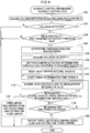
- Seatbelt control processing is repeatedly executed by the seatbelt control ECU 24 while an ignition switch of the vehicle 38 is ON.
- the seatbelt control ECU 24 acquires a collision detection result including the deceleration G detected by the floor sensor 14 and the deceleration Gs detected by the satellite sensors 16.
- the seatbelt control ECU 24 determines whether or not a collision between the vehicle 38 and an object has been detected, based on the collision detection result acquired at step 100. As an example of the determination made at step 102, the seatbelt control ECU 24 may determine whether or not at least one out of the deceleration G or the deceleration Gs has exceeded a predetermined value (for example a value lower than a threshold Gth1, described later), and may determine that a collision has been detected in a case in which this determination is affirmative.
- a predetermined value for example a value lower than a threshold Gth1, described later
- a pressure sensor may be provided to a bumper of the vehicle 38, and whether or not pressure has been applied to the bumper may be a consideration in the collision detection determination. In a case in which a negative determination is made at step 102, the seatbelt control processing is ended.
- step 104 the seatbelt control ECU 24 determines whether or not the deceleration G acquired at step 100 exceeds the preset pre-tensioner activation threshold Gth1.
- the present collision can be determined to be a light collision that does not require activation of the pre-tensioner section 58, and so the seatbelt control processing is ended.
- the pre-tensioner activation threshold Gth1 is an example of a first threshold.
- the present collision can be determined to be a collision requiring activation of the pre-tensioner section 58, and so processing proceeds to step 106.
- the seatbelt control ECU 24 outputs a pre-tensioner inflator ignition signal to the pre-tensioner drive circuit 34.
- the pre-tensioner drive circuit 34 thereby ignites the pre-tensioner inflator 78, accompanying which the spool 52 is rotated by the pre-tensioner section 58 and the seatbelt 66 is retracted, such that the occupant is restrained.
- the seatbelt control ECU 24 acquires the relative speed (collision velocity V) of the object that has collided with the vehicle 38 from the radar device 18.
- the seatbelt control ECU 24 may acquire the relative speed of the object that is the shortest distance from the vehicle 38 as the collision velocity V, based on the relative positions of each object held by the radar device 18.
- the seatbelt control ECU 24 sets a force limiter activation determination threshold Gth2 based on the collision velocity V acquired at step 108.
- the force limiter activation determination threshold Gth2 is an example of a second threshold.
- a relationship between the collision velocity V and the force limiter activation determination threshold Gth2 is defined in a threshold setting map, such that the force limiter activation determination threshold Gth2 decreases as the collision velocity V increases.
- the force limiter activation determination threshold Gth2 corresponding to the collision velocity V acquired at step 108 is read from the threshold setting map and set.
- the force limiter activation determination threshold Gth2 is set to a lower value than the force limiter activation determination threshold Gth2 when the collision velocity V does not exceed this predetermined value.
- the threshold setting map defining the relationship between the collision velocity V and the threshold Gth2 such that the force limiter activation determination threshold Gth2 is lowered as the collision velocity V increases is not limited to the example illustrated in Fig. 6A .
- the force limiter activation determination threshold Gth2 may be adjusted in a non-linear manner with respect to change in the collision velocity V, or as illustrated in Fig. 6C , for example, the force limiter activation determination threshold Gth2 may be adjusted in steps with respect to change in the collision velocity V.
- the force limiter activation determination threshold Gth2 is set to a value equal to or lower than the force limiter activation determination threshold Gth2 when the collision velocity V does not exceed the predetermined value.
- the relationship between the collision velocity V and the threshold Gth2 may also be defined using another format instead of a map, for example using a function or a table.
- the seatbelt control ECU 24 starts timing a determination time period A used to determine setting of a starting load for tension reduction of the seatbelt 66 by the force limiter section 60.
- the starting load for tension reduction of the seatbelt 66 is set to a high load (F1 in Fig. 4 ) in a state in which the force limiter MGG 76 of the force limiter section 60 is not ignited.
- the determination time period A is equivalent to the time taken from activation of the pre-tensioner section 58 until determination of the starting load for tension reduction by the force limiter section 60 is completed.
- the length of the determination time period A is thereby set based on the results of advance testing or the like, such that there is no delay in switching from the high load to the low load in a case in which a collision requires the starting load for tension reduction by the force limiter section 60 to be set to the low load.
- step 114 the seatbelt control ECU 24 acquires the deceleration G detected by the floor sensor 14 from the floor sensor 14.
- step 116 the seatbelt control ECU 24 determines whether or not the deceleration G acquired at step 114 exceeds the force limiter activation determination threshold Gth2 previously set at step 110. In a case in which a negative determination is made at step 116, processing proceeds to step 118.
- step 118 the seatbelt control ECU 24 determines whether or not the determination time period A has elapsed. In a case in which a negative determination is made at step 118, processing returns to step 114, and the processing of steps 114 to 118 is repeated until the determination of either step 116 or step 118 is affirmative.
- step 116 the deceleration G exceeds the force limiter activation determination threshold Gth2 within the determination time period A.
- an affirmative determination is made at step 116, and as illustrated at step 120, the seatbelt control processing is ended without outputting an ignition signal to the force limiter drive circuit 36.
- the force limiter MGG 76 is not ignited, thereby maintaining the starting load for tension reduction of the seatbelt 66 by the force limiter section 60 at the initial high load setting (F1 in Fig. 4 ).
- step 122 the seatbelt control ECU 24 outputs a force limiter MGG ignition signal to the force limiter drive circuit 36, and the seatbelt control processing is ended.
- the force limiter drive circuit 36 accordingly ignites the force limiter MGG 76, and gas generated by the force limiter MGG 76 moves the cam 74, such that the meshing of the cam 74 and the gear 72 is released.
- the starting load for tension reduction of the seatbelt 66 by the force limiter section 60 is switched from the high load to the low load (F2 in Fig. 4 ) accompanying this.
- the content of the above-described seatbelt control processing is schematically illustrated in Fig. 7 .
- the deceleration G detected by the floor sensor 14 is input to a pre-tensioner activation determination section 80 and to a force limiter activation determination section 82.
- the pre-tensioner activation determination section 80 determines whether or not to activate the pre-tensioner section 58 based on collision detection results including the deceleration Gs detected by the satellite sensors 16 as well as the deceleration G.
- a pre-tensioner inflator ignition signal is output to activate the pre-tensioner section 58, and a determination time period timer 84 starts timing the determination time period A.
- the determination time period timer 84 has a low level output while timing the determination time period A.
- the collision velocity V detected by the radar device 18 is also input to the force limiter activation determination section 82.
- the force limiter activation determination section 82 determines the starting load for tension reduction of the seatbelt 66 by the force limiter section 60 based on a force limiter load determination map, illustrated in Fig. 7 . Namely, in the map illustrated in Fig. 7 , a two-dimensional space with the collision velocity V and the deceleration G as the respective coordinate axes is divided into a high load setting region and a low load setting region, and the force limiter activation determination section 82 determines in which of these regions the combination of the input deceleration G and the collision velocity V lies. Note that in the map illustrated in Fig.
- a boundary line between the high load setting region and the low load setting region corresponds to the adjustment of the force limiter activation determination threshold Gth2 with respect to change in the collision velocity V.
- the force limiter activation determination section 82 outputs at a low level in a case in which the appropriate starting load for tension reduction by the force limiter section 60 has been determined to be the high load, and outputs at a high level in a case in which the appropriate starting load for tension reduction by the force limiter section 60 has been determined to be the low load.
- the output of the determination time period timer 84 and the output of the force limiter activation determination section 82 are input to an AND computation section 86.
- the AND computation section 86 After the determination time period A has elapsed since the determination time period timer 84 started and the output of the determination time period timer 84 has become high level, the AND computation section 86 outputs a high level signal in a case in which the output of the force limiter activation determination section 82 is also high level.
- the output of the AND computation section 86 corresponds to a force limiter MGG ignition signal. In a case in which the output of the AND computation section 86 becomes high level, the starting load for tension reduction by the force limiter section 60 is switched to the low load. In a case in which the output of the AND computation section 86 remains low level, the starting load for tension reduction by the force limiter section 60 remains at the high load.
- Fig. 8 illustrates examples of collisions with low impact intensity during an initial collision stage.
- the solid line 90 illustrates change in the deceleration G in a high-speed collision between the vehicle 38 and an object with a soft leading end (a first collision).
- the dashed line 92 illustrates change in the deceleration G in a low-speed collision between the vehicle 38 and a hard object (a second collision).
- the transition of the deceleration G during the determination time period A is at a similar level in both the first collision and the second collision. Therefore, it is not possible to set the starting load for tension reduction by the force limiter section 60 appropriately, by simply comparing the deceleration G against a single threshold during the determination time period A.
- the force limiter activation determination threshold Gth2 against which the deceleration G is compared during the determination time period A, is adjusted so as to lower the force limiter activation determination threshold Gth2 as the collision velocity V increases.
- the force limiter activation determination threshold Gth2 is set to a relatively low value in the first collision with a high collision velocity, as indicated by Gth2(Hi) in Fig. 8 as an example.
- the deceleration G within the determination time period A exceeds the force limiter activation determination threshold Gth2(Hi) that is set to a relatively low value, and so, the starting load for tension reduction by the force limiter section 60 is set to the high load.
- the force limiter activation determination threshold Gth2 is set to a relatively high value, as indicated by Gth2(Lo) in Fig. 8 as an example.
- the deceleration G within the determination time period A does not exceed the force limiter activation determination threshold Gth2(Lo) that is set to a relatively high value, and so the starting load for tension reduction by the force limiter section 60 is set to the low load.
- the seatbelt control ECU 24 sets a force limiter activation determination threshold IGth, this being a threshold for the deceleration integral value IG, according to the collision velocity V acquired at step 108.
- a relationship between the collision velocity V and the force limiter activation determination threshold IGth is set out in a threshold setting map in which the force limiter activation determination threshold IGth becomes lower as the collision velocity V increases.
- a force limiter activation determination threshold IGth corresponding to the collision velocity V acquired at step 108 is read from the threshold setting map and is set.
- the force limiter activation determination threshold IGth is set at a lower value than the force limiter activation determination threshold IGth in a case in which the collision velocity V does not exceed this predetermined value.
- the force limiter activation determination threshold IGth is an example of a second threshold.
- step 115 the seatbelt control ECU 24 acquires the deceleration G from the floor sensor 14 and adds the acquired deceleration G to the deceleration integral value IG.
- the processing of step 115 is repeated until the determination at either step 117 or step 118 is affirmative.
- the deceleration integral value IG is a value obtained as a result of integrating the deceleration G from the start of the determination time period A.
- step 117 the seatbelt control ECU 24 determines whether or not the deceleration integral value IG computed at step 115 exceeds the force limiter activation determination threshold IGth previously set at step 109. In a case in which a negative determination is made at step 117, processing proceeds to step 118. The processing of steps 115, 117, and 118 is thereby repeated until the determination at either step 117 or step 118 is affirmative.
- step 117 processing proceeds to step 120 similarly to in the first exemplary embodiment, and the starting load for tension reduction by the force limiter section 60 is maintained at the initial high load setting.
- step 118 processing proceeds to step 122 similarly to in the first exemplary embodiment, and the starting load for tension reduction by the force limiter section 60 is switched from the high load to the low load.
- the deceleration G is compared against the force limiter activation determination threshold Gth2 to make determination regarding force limiter activation.
- the determination result regarding force limiter activation might be influenced by a momentary fluctuation in the deceleration G caused by the incorporation of noise or the like during the determination time period A.
- the deceleration integral value IG is used instead of the deceleration G to make the determination regarding force limiter activation.
- Fluctuations in the value of the deceleration integral value IG are thereby suppressed, such that even if the deceleration G momentarily fluctuates during the determination time period A due to the incorporation of noise or the like, any influence on the determination result regarding force limiter activation can be suppressed.
- Fig. 11 illustrates a configuration provided with a stereo camera 40 that captures images of the surroundings of the vehicle 38 using plural cameras.
- the stereo camera 40 is capable of detecting the distance to an object corresponding to an imaging subject in a captured image, and is also capable of detecting the relative speed of the object based on changes in the distance to the detected object over time, and so the stereo camera 40 may be employed as a second detection section.
- a combination of the radar device 18 and a camera may be employed as a second detection section.
- a stereo camera or a single lens camera may be employed as the camera.
- an ultrasound sensor or a laser radar may be employed as a second detection section.
- the floor sensor 14 detects the deceleration G as an example of a physical quantity relating to the magnitude of a collision; however, the physical quantity is not limited to the deceleration G.
- the physical quantity is not limited to the deceleration G.
- one out of an integral value of the deceleration G, a differential value of the deceleration G, or the size of a colliding object detectable in images captured by a camera may be employed individually, or at least one of these may be employed in combination with the deceleration G.
- pre-tensioner section 58 may be configured so as to be activated prior to a collision occurring in a case in which a collision has been predicted by a collision prediction section.
- An example including a collision prediction section is illustrated in Fig. 12 .
- the radar device 18, a camera 42, and a pre-crash control ECU 44 function as the collision prediction section. Note that "pre-crash” is hereafter abbreviated to "PC”.
- the PC control ECU 44 detects the position of each monitoring target object in an image input from the camera 42 based on information (such as the relative position of each monitoring target object) input from the radar device 18.
- the PC control ECU 44 also extracts feature amounts of each monitoring target object, and identifies the nature of the monitoring target object (such as a pedestrian or a vehicle) based on the extracted feature amounts.
- the PC control ECU 44 tracks monitoring target objects present in a predetermined range by repeating the above processing, and computes a probability of a collision with the vehicle for each monitoring target object.
- the PC control ECU 44 If the PC control ECU 44 detects the probability of a collision between a monitoring target object and the vehicle to be a predetermined value or greater (predicts a collision between the vehicle and a monitoring target object), the PC control ECU 44 transmits a collision prediction signal to specific ECUs in the onboard system 10, including the seatbelt control ECU 24. Note that collision prediction is not limited to employing information input from both the radar device 18 and the camera 42, and for example, a collision may be predicted based on information input from one out of the radar device 18 or the camera 42.
- the pre-tensioner section 58 may be activated prior to the collision occurring.
- the timing at which to start timing the determination time period A for making the determination regarding activation of the force limiter may be set to a timing at which the collision is detected after the pre-tensioner section 58 has been activated, or may be set to the timing at which the pre-tensioner section 58 is activated.
- the force limiter section 60 is configured such that the starting load for tension reduction of the seatbelt 66 is maintained at the high load in a case in which the force limiter MGG 76 is not ignited, and the starting load for tension reduction is switched to the low load in a case in which the force limiter MGG 76 is ignited.
- a force limiter section is not limited to a configuration in which the starting load for tension reduction is switched between two levels as described above.
- a configuration may be applied in which the starting load for tension reduction can be varied between three or more levels.
- plural second thresholds with different values to each other are employed in order to determine which out of the three or more levels of the starting load for tension reduction to switch to. Applying the present disclosure in such cases enables each second threshold to be adjusted and set according to the collision velocity.
- the spring mechanism 79 retracts the seatbelt 66
- the pre-tensioner section 58 retracts slack in the seatbelt 66
- the force limiter section 60 regulates the tension of the seatbelt 66.
- development of a motor with higher torque would enable the configuration of a seatbelt retractor device to be modified such that retract of a seatbelt and regulation of tension were performed by the motor.
- the present disclosure could be applied to a seatbelt retractor device with such a configuration, albeit with at least one out of the function of the pre-tensioner section or the function of the force limiter section being realized by drive force of the motor.
Landscapes
- Engineering & Computer Science (AREA)
- Mechanical Engineering (AREA)
- Automation & Control Theory (AREA)
- Automotive Seat Belt Assembly (AREA)
- Seats For Vehicles (AREA)
Claims (4)
- Sicherheitsgurt-Steuervorrichtung (10), umfassend:eine Vorspannsektion (58), die dazu ausgestaltet ist, einen Sicherheitsgurt (66) zurückzuziehen, um eine Spannung des Sicherheitsgurtes (66) zu erhöhen,eine Kraftbegrenzungssektion (60), die dazu ausgestaltet ist, eine Größe einer Last zu ändern, bei der mit einem Verringern einer Spannung des Sicherheitsgurtes (66) begonnen werden soll, der durch die Vorspannsektion (58) zurückgezogen wird, undeine Steuereinheit (24, 36), die dazu ausgestaltet ist, die Vorspannsektion (58) in einem Fall, in dem eine physikalische Größe, die sich auf eine Größenordnung einer Kollision bezieht, die von einer ersten Erfassungssektion (14) zum Erfassen der physikalischen Größe erfasst wird, einen ersten Schwellenwert überschreitet oder in einem Fall, in dem eine Kollision durch eine Kollisionsvorhersagesektion (18) vorhergesagt worden ist, zu aktivieren, wobei die Steuereinheit (24, 36) dazu ausgestaltet ist, die Last der Kraftbegrenzungssektion (60) in einem Fall zu steuern, in dem innerhalb eines vorbestimmten Zeitraums nach Aktivierung der Vorspannsektion (58) die von der ersten Erfassungssektion (14) erfasste physikalische Größe einen zweiten Schwellenwert überschritten hat, der gemäß einer von einer zweiten Erfassungssektion (18, 40) erfassten Kollisionsgeschwindigkeit eingestellt wurde, um eine größere Last als die Last der Kraftbegrenzungssektion (60) in einem Fall zu sein, in dem die physikalische Größe den zweiten Schwellenwert innerhalb des vorbestimmten Zeitraums nicht überschritten hat.
- Sicherheitsgurt-Steuervorrichtung nach Anspruch 1, wobei die Steuereinheit (24, 36) dazu ausgestaltet ist, den zweiten Schwellenwert, der in einem Fall angewandt wird, in dem die Kollisionsgeschwindigkeit einen vorbestimmten Wert überschritten hat, auf einen Wert einzustellen, der nicht größer als der zweite Schwellenwert ist, der in einem Fall angewandt wird, in dem die Kollisionsgeschwindigkeit den vorbestimmten Wert nicht überschritten hat.
- Sicherheitsgurt-Steuervorrichtung nach Anspruch 1 oder Anspruch 2, wobei die zweite Erfassungssektion (18, 40) mindestens eines von einem Radar (18) oder einer Kamera (40) ist.
- Sicherheitsgurt-Steuervorrichtung nach einem von Anspruch 1 bis Anspruch 3, wobei:
die erste Erfassungssektion (14) dazu ausgestaltet ist, eine Verlangsamung als die physikalische Größe zu erfassen, und
die Steuereinheit (24, 36) dazu ausgestaltet ist, einen Schwellenwert für einen Integralwert der Verlangsamung, der von der ersten Erfassungssektion (14) gemäß der Kollisionsgeschwindigkeit erfasst wird, als den zweiten Schwellenwert einzustellen und zu bestimmen, ob der Integralwert der Verlangsamung den eingestellten zweiten Schwellenwert innerhalb eines vorbestimmten Zeitraums, nachdem die Vorspannsektion (58) aktiviert wurde, überschritten hat oder nicht.
Applications Claiming Priority (1)
| Application Number | Priority Date | Filing Date | Title |
|---|---|---|---|
| JP2018056229A JP6958452B2 (ja) | 2018-03-23 | 2018-03-23 | シートベルト制御装置 |
Publications (2)
| Publication Number | Publication Date |
|---|---|
| EP3543073A1 EP3543073A1 (de) | 2019-09-25 |
| EP3543073B1 true EP3543073B1 (de) | 2020-09-16 |
Family
ID=65904097
Family Applications (1)
| Application Number | Title | Priority Date | Filing Date |
|---|---|---|---|
| EP19164043.2A Active EP3543073B1 (de) | 2018-03-23 | 2019-03-20 | Sitzgurtsteuerungsvorrichtung |
Country Status (4)
| Country | Link |
|---|---|
| US (1) | US10967831B2 (de) |
| EP (1) | EP3543073B1 (de) |
| JP (1) | JP6958452B2 (de) |
| CN (1) | CN110293935B (de) |
Families Citing this family (3)
| Publication number | Priority date | Publication date | Assignee | Title |
|---|---|---|---|---|
| JP7205309B2 (ja) | 2019-03-04 | 2023-01-17 | トヨタ自動車株式会社 | 車両用乗員保護装置 |
| CN111688621B (zh) * | 2020-06-17 | 2021-10-12 | 中国第一汽车股份有限公司 | 一种汽车碰撞乘员保护方法、装置及系统 |
| DE102024001300A1 (de) * | 2024-04-24 | 2025-10-30 | Mercedes-Benz Group AG | Verfahren zum Steuern eines Insassenrückhaltemittels in einem Fahrzeug |
Family Cites Families (11)
| Publication number | Priority date | Publication date | Assignee | Title |
|---|---|---|---|---|
| WO2000013944A1 (de) * | 1998-09-04 | 2000-03-16 | Siemens Aktiengesellschaft | Verfahren zum steuern eines insassenschutzmittels mittels dynamischer schaltsch wellen sowie steuervorrichtung hierfür |
| JP4278818B2 (ja) | 2000-03-21 | 2009-06-17 | 株式会社東海理化電機製作所 | ウェビング巻取装置及び車両 |
| SE521720C2 (sv) * | 2002-01-16 | 2003-12-02 | Bo Swedenklef | Variabel kraftbegränsare för säkerhetsbälte |
| GB2424982A (en) * | 2005-04-07 | 2006-10-11 | Autoliv Dev | Seatbelt pretensioner dependent on steering rate |
| JP4908927B2 (ja) | 2005-08-22 | 2012-04-04 | 株式会社東海理化電機製作所 | ウエビング巻取装置 |
| JP4811942B2 (ja) | 2006-11-01 | 2011-11-09 | タカタ株式会社 | シートベルトリトラクタおよびこれを備えているシートベルト装置 |
| JP4438873B2 (ja) | 2008-02-15 | 2010-03-24 | トヨタ自動車株式会社 | シートベルト制御装置 |
| DE102011102298B4 (de) * | 2011-05-23 | 2014-03-06 | Audi Ag | Verfahren zum Steuern von Rückhalteeinrichtungen eines Kraftfahrzeugs |
| JP5323223B2 (ja) | 2012-03-16 | 2013-10-23 | タカタ株式会社 | シートベルトリトラクタおよびこれを備えているシートベルト装置 |
| DE102012024270A1 (de) * | 2012-12-12 | 2014-06-12 | Trw Automotive Gmbh | Kraftbegrenzungseinrichtung sowie Verfahren zur Steuerung einer Kraftbegrenzungseinrichtung |
| CN204296643U (zh) * | 2014-09-10 | 2015-04-29 | 安徽工程大学 | 一种预紧式汽车安全带 |
-
2018
- 2018-03-23 JP JP2018056229A patent/JP6958452B2/ja active Active
-
2019
- 2019-01-25 US US16/257,449 patent/US10967831B2/en active Active
- 2019-01-31 CN CN201910100774.4A patent/CN110293935B/zh active Active
- 2019-03-20 EP EP19164043.2A patent/EP3543073B1/de active Active
Non-Patent Citations (1)
| Title |
|---|
| None * |
Also Published As
| Publication number | Publication date |
|---|---|
| CN110293935B (zh) | 2022-02-08 |
| US20190291689A1 (en) | 2019-09-26 |
| US10967831B2 (en) | 2021-04-06 |
| JP2019166970A (ja) | 2019-10-03 |
| EP3543073A1 (de) | 2019-09-25 |
| JP6958452B2 (ja) | 2021-11-02 |
| CN110293935A (zh) | 2019-10-01 |
Similar Documents
| Publication | Publication Date | Title |
|---|---|---|
| CN107521448B (zh) | 用于控制车辆的安全装置的操作的方法及控制装置 | |
| US11040693B2 (en) | Vehicular protection device and vehicle | |
| EP3309018B1 (de) | Insassenrückhaltevorrichtung für fahrzeug | |
| CN108454560B (zh) | 用于车辆的可变式力限制器控制系统 | |
| US6784791B2 (en) | Potential collision detection and parking aid system | |
| US20160082912A1 (en) | Airbag deployment control apparatus and method | |
| EP3543073B1 (de) | Sitzgurtsteuerungsvorrichtung | |
| US10196023B2 (en) | Vehicle collision detection system | |
| CN114802089B (zh) | 一种车辆安全气囊的控制方法及控制系统 | |
| US20120330512A1 (en) | Method for triggering at least one irreversible retaining device of a motor vehicle | |
| US6864783B2 (en) | Potential collision detection and reversing aid system | |
| KR20040076612A (ko) | 승원 구속 시스템 | |
| CN107499272B (zh) | 用于控制车辆的人员保护装置的方法和控制器 | |
| US20080269991A1 (en) | Activation-Control Device for Occupant Crash-Protection Apparatus | |
| US11235722B2 (en) | Seatbelt system for vehicle, and control method for seatbelt system | |
| JP2010516548A (ja) | 人員保護手段をトリガする方法および制御装置 | |
| CN113619520A (zh) | 在车辆发生碰撞时用于控制车辆乘员保护装置的方法 | |
| JP4263814B2 (ja) | 車両の乗員保護装置 | |
| JP6111990B2 (ja) | シートベルト制御システム、及び、シートベルト制御装置 | |
| JP2018039336A (ja) | フォースリミッタ荷重変更システム | |
| CN104859572B (zh) | 用于触发车辆的人员保护装置的方法及控制装置 | |
| JP4263968B2 (ja) | シートベルト装置 | |
| US20080185825A1 (en) | Device For Triggering a Second Airbag Stage | |
| JP2835982B2 (ja) | 車輌用安全装置の作動制御方法 | |
| WO2018114939A1 (de) | Verfahren und steuergerät zum fussgàngerschutz für ein fahrzeug |
Legal Events
| Date | Code | Title | Description |
|---|---|---|---|
| PUAI | Public reference made under article 153(3) epc to a published international application that has entered the european phase |
Free format text: ORIGINAL CODE: 0009012 |
|
| STAA | Information on the status of an ep patent application or granted ep patent |
Free format text: STATUS: REQUEST FOR EXAMINATION WAS MADE |
|
| 17P | Request for examination filed |
Effective date: 20190320 |
|
| AK | Designated contracting states |
Kind code of ref document: A1 Designated state(s): AL AT BE BG CH CY CZ DE DK EE ES FI FR GB GR HR HU IE IS IT LI LT LU LV MC MK MT NL NO PL PT RO RS SE SI SK SM TR |
|
| AX | Request for extension of the european patent |
Extension state: BA ME |
|
| GRAP | Despatch of communication of intention to grant a patent |
Free format text: ORIGINAL CODE: EPIDOSNIGR1 |
|
| STAA | Information on the status of an ep patent application or granted ep patent |
Free format text: STATUS: GRANT OF PATENT IS INTENDED |
|
| INTG | Intention to grant announced |
Effective date: 20200424 |
|
| GRAS | Grant fee paid |
Free format text: ORIGINAL CODE: EPIDOSNIGR3 |
|
| GRAA | (expected) grant |
Free format text: ORIGINAL CODE: 0009210 |
|
| STAA | Information on the status of an ep patent application or granted ep patent |
Free format text: STATUS: THE PATENT HAS BEEN GRANTED |
|
| AK | Designated contracting states |
Kind code of ref document: B1 Designated state(s): AL AT BE BG CH CY CZ DE DK EE ES FI FR GB GR HR HU IE IS IT LI LT LU LV MC MK MT NL NO PL PT RO RS SE SI SK SM TR |
|
| REG | Reference to a national code |
Ref country code: GB Ref legal event code: FG4D |
|
| REG | Reference to a national code |
Ref country code: CH Ref legal event code: EP |
|
| REG | Reference to a national code |
Ref country code: DE Ref legal event code: R096 Ref document number: 602019000680 Country of ref document: DE |
|
| REG | Reference to a national code |
Ref country code: IE Ref legal event code: FG4D |
|
| REG | Reference to a national code |
Ref country code: AT Ref legal event code: REF Ref document number: 1313900 Country of ref document: AT Kind code of ref document: T Effective date: 20201015 |
|
| PG25 | Lapsed in a contracting state [announced via postgrant information from national office to epo] |
Ref country code: BG Free format text: LAPSE BECAUSE OF FAILURE TO SUBMIT A TRANSLATION OF THE DESCRIPTION OR TO PAY THE FEE WITHIN THE PRESCRIBED TIME-LIMIT Effective date: 20201216 Ref country code: HR Free format text: LAPSE BECAUSE OF FAILURE TO SUBMIT A TRANSLATION OF THE DESCRIPTION OR TO PAY THE FEE WITHIN THE PRESCRIBED TIME-LIMIT Effective date: 20200916 Ref country code: SE Free format text: LAPSE BECAUSE OF FAILURE TO SUBMIT A TRANSLATION OF THE DESCRIPTION OR TO PAY THE FEE WITHIN THE PRESCRIBED TIME-LIMIT Effective date: 20200916 Ref country code: FI Free format text: LAPSE BECAUSE OF FAILURE TO SUBMIT A TRANSLATION OF THE DESCRIPTION OR TO PAY THE FEE WITHIN THE PRESCRIBED TIME-LIMIT Effective date: 20200916 Ref country code: GR Free format text: LAPSE BECAUSE OF FAILURE TO SUBMIT A TRANSLATION OF THE DESCRIPTION OR TO PAY THE FEE WITHIN THE PRESCRIBED TIME-LIMIT Effective date: 20201217 Ref country code: NO Free format text: LAPSE BECAUSE OF FAILURE TO SUBMIT A TRANSLATION OF THE DESCRIPTION OR TO PAY THE FEE WITHIN THE PRESCRIBED TIME-LIMIT Effective date: 20201216 |
|
| REG | Reference to a national code |
Ref country code: AT Ref legal event code: MK05 Ref document number: 1313900 Country of ref document: AT Kind code of ref document: T Effective date: 20200916 |
|
| REG | Reference to a national code |
Ref country code: NL Ref legal event code: MP Effective date: 20200916 |
|
| PG25 | Lapsed in a contracting state [announced via postgrant information from national office to epo] |
Ref country code: LV Free format text: LAPSE BECAUSE OF FAILURE TO SUBMIT A TRANSLATION OF THE DESCRIPTION OR TO PAY THE FEE WITHIN THE PRESCRIBED TIME-LIMIT Effective date: 20200916 Ref country code: RS Free format text: LAPSE BECAUSE OF FAILURE TO SUBMIT A TRANSLATION OF THE DESCRIPTION OR TO PAY THE FEE WITHIN THE PRESCRIBED TIME-LIMIT Effective date: 20200916 |
|
| REG | Reference to a national code |
Ref country code: LT Ref legal event code: MG4D |
|
| PG25 | Lapsed in a contracting state [announced via postgrant information from national office to epo] |
Ref country code: LT Free format text: LAPSE BECAUSE OF FAILURE TO SUBMIT A TRANSLATION OF THE DESCRIPTION OR TO PAY THE FEE WITHIN THE PRESCRIBED TIME-LIMIT Effective date: 20200916 Ref country code: SM Free format text: LAPSE BECAUSE OF FAILURE TO SUBMIT A TRANSLATION OF THE DESCRIPTION OR TO PAY THE FEE WITHIN THE PRESCRIBED TIME-LIMIT Effective date: 20200916 Ref country code: RO Free format text: LAPSE BECAUSE OF FAILURE TO SUBMIT A TRANSLATION OF THE DESCRIPTION OR TO PAY THE FEE WITHIN THE PRESCRIBED TIME-LIMIT Effective date: 20200916 Ref country code: PT Free format text: LAPSE BECAUSE OF FAILURE TO SUBMIT A TRANSLATION OF THE DESCRIPTION OR TO PAY THE FEE WITHIN THE PRESCRIBED TIME-LIMIT Effective date: 20210118 Ref country code: CZ Free format text: LAPSE BECAUSE OF FAILURE TO SUBMIT A TRANSLATION OF THE DESCRIPTION OR TO PAY THE FEE WITHIN THE PRESCRIBED TIME-LIMIT Effective date: 20200916 Ref country code: EE Free format text: LAPSE BECAUSE OF FAILURE TO SUBMIT A TRANSLATION OF THE DESCRIPTION OR TO PAY THE FEE WITHIN THE PRESCRIBED TIME-LIMIT Effective date: 20200916 |
|
| PG25 | Lapsed in a contracting state [announced via postgrant information from national office to epo] |
Ref country code: AL Free format text: LAPSE BECAUSE OF FAILURE TO SUBMIT A TRANSLATION OF THE DESCRIPTION OR TO PAY THE FEE WITHIN THE PRESCRIBED TIME-LIMIT Effective date: 20200916 Ref country code: AT Free format text: LAPSE BECAUSE OF FAILURE TO SUBMIT A TRANSLATION OF THE DESCRIPTION OR TO PAY THE FEE WITHIN THE PRESCRIBED TIME-LIMIT Effective date: 20200916 Ref country code: ES Free format text: LAPSE BECAUSE OF FAILURE TO SUBMIT A TRANSLATION OF THE DESCRIPTION OR TO PAY THE FEE WITHIN THE PRESCRIBED TIME-LIMIT Effective date: 20200916 Ref country code: IS Free format text: LAPSE BECAUSE OF FAILURE TO SUBMIT A TRANSLATION OF THE DESCRIPTION OR TO PAY THE FEE WITHIN THE PRESCRIBED TIME-LIMIT Effective date: 20210116 Ref country code: PL Free format text: LAPSE BECAUSE OF FAILURE TO SUBMIT A TRANSLATION OF THE DESCRIPTION OR TO PAY THE FEE WITHIN THE PRESCRIBED TIME-LIMIT Effective date: 20200916 |
|
| REG | Reference to a national code |
Ref country code: DE Ref legal event code: R097 Ref document number: 602019000680 Country of ref document: DE |
|
| PG25 | Lapsed in a contracting state [announced via postgrant information from national office to epo] |
Ref country code: SK Free format text: LAPSE BECAUSE OF FAILURE TO SUBMIT A TRANSLATION OF THE DESCRIPTION OR TO PAY THE FEE WITHIN THE PRESCRIBED TIME-LIMIT Effective date: 20200916 |
|
| PLBE | No opposition filed within time limit |
Free format text: ORIGINAL CODE: 0009261 |
|
| STAA | Information on the status of an ep patent application or granted ep patent |
Free format text: STATUS: NO OPPOSITION FILED WITHIN TIME LIMIT |
|
| 26N | No opposition filed |
Effective date: 20210617 |
|
| PG25 | Lapsed in a contracting state [announced via postgrant information from national office to epo] |
Ref country code: SI Free format text: LAPSE BECAUSE OF FAILURE TO SUBMIT A TRANSLATION OF THE DESCRIPTION OR TO PAY THE FEE WITHIN THE PRESCRIBED TIME-LIMIT Effective date: 20200916 Ref country code: DK Free format text: LAPSE BECAUSE OF FAILURE TO SUBMIT A TRANSLATION OF THE DESCRIPTION OR TO PAY THE FEE WITHIN THE PRESCRIBED TIME-LIMIT Effective date: 20200916 |
|
| PG25 | Lapsed in a contracting state [announced via postgrant information from national office to epo] |
Ref country code: MC Free format text: LAPSE BECAUSE OF FAILURE TO SUBMIT A TRANSLATION OF THE DESCRIPTION OR TO PAY THE FEE WITHIN THE PRESCRIBED TIME-LIMIT Effective date: 20200916 Ref country code: IT Free format text: LAPSE BECAUSE OF FAILURE TO SUBMIT A TRANSLATION OF THE DESCRIPTION OR TO PAY THE FEE WITHIN THE PRESCRIBED TIME-LIMIT Effective date: 20200916 |
|
| REG | Reference to a national code |
Ref country code: BE Ref legal event code: MM Effective date: 20210331 |
|
| PG25 | Lapsed in a contracting state [announced via postgrant information from national office to epo] |
Ref country code: LU Free format text: LAPSE BECAUSE OF NON-PAYMENT OF DUE FEES Effective date: 20210320 Ref country code: IE Free format text: LAPSE BECAUSE OF NON-PAYMENT OF DUE FEES Effective date: 20210320 |
|
| PG25 | Lapsed in a contracting state [announced via postgrant information from national office to epo] |
Ref country code: BE Free format text: LAPSE BECAUSE OF NON-PAYMENT OF DUE FEES Effective date: 20210331 |
|
| REG | Reference to a national code |
Ref country code: CH Ref legal event code: PL |
|
| PG25 | Lapsed in a contracting state [announced via postgrant information from national office to epo] |
Ref country code: LI Free format text: LAPSE BECAUSE OF NON-PAYMENT OF DUE FEES Effective date: 20220331 Ref country code: CH Free format text: LAPSE BECAUSE OF NON-PAYMENT OF DUE FEES Effective date: 20220331 |
|
| P01 | Opt-out of the competence of the unified patent court (upc) registered |
Effective date: 20230427 |
|
| REG | Reference to a national code |
Ref country code: DE Ref legal event code: R084 Ref document number: 602019000680 Country of ref document: DE |
|
| PG25 | Lapsed in a contracting state [announced via postgrant information from national office to epo] |
Ref country code: NL Free format text: LAPSE BECAUSE OF NON-PAYMENT OF DUE FEES Effective date: 20200923 Ref country code: CY Free format text: LAPSE BECAUSE OF FAILURE TO SUBMIT A TRANSLATION OF THE DESCRIPTION OR TO PAY THE FEE WITHIN THE PRESCRIBED TIME-LIMIT Effective date: 20200916 |
|
| PG25 | Lapsed in a contracting state [announced via postgrant information from national office to epo] |
Ref country code: HU Free format text: LAPSE BECAUSE OF FAILURE TO SUBMIT A TRANSLATION OF THE DESCRIPTION OR TO PAY THE FEE WITHIN THE PRESCRIBED TIME-LIMIT; INVALID AB INITIO Effective date: 20190320 |
|
| REG | Reference to a national code |
Ref country code: GB Ref legal event code: 746 Effective date: 20230815 |
|
| PG25 | Lapsed in a contracting state [announced via postgrant information from national office to epo] |
Ref country code: MK Free format text: LAPSE BECAUSE OF FAILURE TO SUBMIT A TRANSLATION OF THE DESCRIPTION OR TO PAY THE FEE WITHIN THE PRESCRIBED TIME-LIMIT Effective date: 20200916 |
|
| PG25 | Lapsed in a contracting state [announced via postgrant information from national office to epo] |
Ref country code: MT Free format text: LAPSE BECAUSE OF FAILURE TO SUBMIT A TRANSLATION OF THE DESCRIPTION OR TO PAY THE FEE WITHIN THE PRESCRIBED TIME-LIMIT Effective date: 20200916 |
|
| PG25 | Lapsed in a contracting state [announced via postgrant information from national office to epo] |
Ref country code: TR Free format text: LAPSE BECAUSE OF FAILURE TO SUBMIT A TRANSLATION OF THE DESCRIPTION OR TO PAY THE FEE WITHIN THE PRESCRIBED TIME-LIMIT Effective date: 20200916 |
|
| PGFP | Annual fee paid to national office [announced via postgrant information from national office to epo] |
Ref country code: GB Payment date: 20260202 Year of fee payment: 8 |
|
| PGFP | Annual fee paid to national office [announced via postgrant information from national office to epo] |
Ref country code: DE Payment date: 20260128 Year of fee payment: 8 |
|
| PGFP | Annual fee paid to national office [announced via postgrant information from national office to epo] |
Ref country code: FR Payment date: 20260209 Year of fee payment: 8 |