EP3543059B1 - Procédé de calcul d'une surimpression des informations supplémentaires pour un affichage sur une unité d'affichage, dispositif de mise en oeuvre du procédé, ainsi que véhicule automobile et programme informatique - Google Patents
Procédé de calcul d'une surimpression des informations supplémentaires pour un affichage sur une unité d'affichage, dispositif de mise en oeuvre du procédé, ainsi que véhicule automobile et programme informatique Download PDFInfo
- Publication number
- EP3543059B1 EP3543059B1 EP19157312.0A EP19157312A EP3543059B1 EP 3543059 B1 EP3543059 B1 EP 3543059B1 EP 19157312 A EP19157312 A EP 19157312A EP 3543059 B1 EP3543059 B1 EP 3543059B1
- Authority
- EP
- European Patent Office
- Prior art keywords
- vehicle
- travelling
- computed
- mark
- observer
- Prior art date
- Legal status (The legal status is an assumption and is not a legal conclusion. Google has not performed a legal analysis and makes no representation as to the accuracy of the status listed.)
- Active
Links
- 238000000034 method Methods 0.000 title claims description 37
- 238000004590 computer program Methods 0.000 title claims description 7
- 238000003780 insertion Methods 0.000 title description 4
- 230000037431 insertion Effects 0.000 title description 4
- 230000000694 effects Effects 0.000 claims description 46
- 230000033228 biological regulation Effects 0.000 claims description 29
- 238000013459 approach Methods 0.000 claims description 14
- 230000033001 locomotion Effects 0.000 claims description 7
- 230000003190 augmentative effect Effects 0.000 claims description 6
- 230000001105 regulatory effect Effects 0.000 claims description 3
- 239000004984 smart glass Substances 0.000 claims 2
- 230000006870 function Effects 0.000 description 16
- 239000010432 diamond Substances 0.000 description 12
- 238000004891 communication Methods 0.000 description 10
- 229910003460 diamond Inorganic materials 0.000 description 10
- 238000001514 detection method Methods 0.000 description 9
- 230000008901 benefit Effects 0.000 description 8
- 230000004438 eyesight Effects 0.000 description 8
- 238000005516 engineering process Methods 0.000 description 7
- 239000011521 glass Substances 0.000 description 7
- 238000004364 calculation method Methods 0.000 description 5
- 230000008569 process Effects 0.000 description 5
- 238000010586 diagram Methods 0.000 description 4
- 239000003550 marker Substances 0.000 description 4
- 238000012544 monitoring process Methods 0.000 description 4
- 230000008859 change Effects 0.000 description 3
- 230000007774 longterm Effects 0.000 description 3
- 230000007935 neutral effect Effects 0.000 description 3
- 230000008447 perception Effects 0.000 description 3
- 238000010276 construction Methods 0.000 description 2
- 230000001276 controlling effect Effects 0.000 description 2
- 238000011161 development Methods 0.000 description 2
- 230000018109 developmental process Effects 0.000 description 2
- 230000006872 improvement Effects 0.000 description 2
- 230000035515 penetration Effects 0.000 description 2
- 238000012545 processing Methods 0.000 description 2
- 230000011664 signaling Effects 0.000 description 2
- 238000012800 visualization Methods 0.000 description 2
- 230000001133 acceleration Effects 0.000 description 1
- 230000004308 accommodation Effects 0.000 description 1
- 230000006978 adaptation Effects 0.000 description 1
- 230000003044 adaptive effect Effects 0.000 description 1
- 238000004378 air conditioning Methods 0.000 description 1
- 238000003491 array Methods 0.000 description 1
- 230000005540 biological transmission Effects 0.000 description 1
- 230000010267 cellular communication Effects 0.000 description 1
- 230000001149 cognitive effect Effects 0.000 description 1
- 230000001427 coherent effect Effects 0.000 description 1
- 230000001419 dependent effect Effects 0.000 description 1
- 238000013461 design Methods 0.000 description 1
- 238000000605 extraction Methods 0.000 description 1
- 238000005562 fading Methods 0.000 description 1
- 239000000835 fiber Substances 0.000 description 1
- 239000012530 fluid Substances 0.000 description 1
- 238000009472 formulation Methods 0.000 description 1
- 230000000977 initiatory effect Effects 0.000 description 1
- 230000003993 interaction Effects 0.000 description 1
- 230000000873 masking effect Effects 0.000 description 1
- 239000000203 mixture Substances 0.000 description 1
- 238000010295 mobile communication Methods 0.000 description 1
- 238000012986 modification Methods 0.000 description 1
- 230000004048 modification Effects 0.000 description 1
- 230000008520 organization Effects 0.000 description 1
- 230000009467 reduction Effects 0.000 description 1
- 238000011160 research Methods 0.000 description 1
- 239000013589 supplement Substances 0.000 description 1
- 101150060058 tag-335 gene Proteins 0.000 description 1
- 230000007704 transition Effects 0.000 description 1
- XLYOFNOQVPJJNP-UHFFFAOYSA-N water Substances O XLYOFNOQVPJJNP-UHFFFAOYSA-N 0.000 description 1
Images


Classifications
-
- B—PERFORMING OPERATIONS; TRANSPORTING
- B60—VEHICLES IN GENERAL
- B60W—CONJOINT CONTROL OF VEHICLE SUB-UNITS OF DIFFERENT TYPE OR DIFFERENT FUNCTION; CONTROL SYSTEMS SPECIALLY ADAPTED FOR HYBRID VEHICLES; ROAD VEHICLE DRIVE CONTROL SYSTEMS FOR PURPOSES NOT RELATED TO THE CONTROL OF A PARTICULAR SUB-UNIT
- B60W30/00—Purposes of road vehicle drive control systems not related to the control of a particular sub-unit, e.g. of systems using conjoint control of vehicle sub-units
- B60W30/08—Active safety systems predicting or avoiding probable or impending collision or attempting to minimise its consequences
-
- B—PERFORMING OPERATIONS; TRANSPORTING
- B60—VEHICLES IN GENERAL
- B60K—ARRANGEMENT OR MOUNTING OF PROPULSION UNITS OR OF TRANSMISSIONS IN VEHICLES; ARRANGEMENT OR MOUNTING OF PLURAL DIVERSE PRIME-MOVERS IN VEHICLES; AUXILIARY DRIVES FOR VEHICLES; INSTRUMENTATION OR DASHBOARDS FOR VEHICLES; ARRANGEMENTS IN CONNECTION WITH COOLING, AIR INTAKE, GAS EXHAUST OR FUEL SUPPLY OF PROPULSION UNITS IN VEHICLES
- B60K35/00—Instruments specially adapted for vehicles; Arrangement of instruments in or on vehicles
-
- G—PHYSICS
- G06—COMPUTING; CALCULATING OR COUNTING
- G06V—IMAGE OR VIDEO RECOGNITION OR UNDERSTANDING
- G06V20/00—Scenes; Scene-specific elements
- G06V20/50—Context or environment of the image
- G06V20/56—Context or environment of the image exterior to a vehicle by using sensors mounted on the vehicle
- G06V20/58—Recognition of moving objects or obstacles, e.g. vehicles or pedestrians; Recognition of traffic objects, e.g. traffic signs, traffic lights or roads
-
- G—PHYSICS
- G02—OPTICS
- G02B—OPTICAL ELEMENTS, SYSTEMS OR APPARATUS
- G02B27/00—Optical systems or apparatus not provided for by any of the groups G02B1/00 - G02B26/00, G02B30/00
- G02B27/01—Head-up displays
- G02B27/0101—Head-up displays characterised by optical features
-
- B—PERFORMING OPERATIONS; TRANSPORTING
- B60—VEHICLES IN GENERAL
- B60K—ARRANGEMENT OR MOUNTING OF PROPULSION UNITS OR OF TRANSMISSIONS IN VEHICLES; ARRANGEMENT OR MOUNTING OF PLURAL DIVERSE PRIME-MOVERS IN VEHICLES; AUXILIARY DRIVES FOR VEHICLES; INSTRUMENTATION OR DASHBOARDS FOR VEHICLES; ARRANGEMENTS IN CONNECTION WITH COOLING, AIR INTAKE, GAS EXHAUST OR FUEL SUPPLY OF PROPULSION UNITS IN VEHICLES
- B60K35/00—Instruments specially adapted for vehicles; Arrangement of instruments in or on vehicles
- B60K35/20—Output arrangements, i.e. from vehicle to user, associated with vehicle functions or specially adapted therefor
- B60K35/21—Output arrangements, i.e. from vehicle to user, associated with vehicle functions or specially adapted therefor using visual output, e.g. blinking lights or matrix displays
- B60K35/23—Head-up displays [HUD]
-
- B—PERFORMING OPERATIONS; TRANSPORTING
- B60—VEHICLES IN GENERAL
- B60K—ARRANGEMENT OR MOUNTING OF PROPULSION UNITS OR OF TRANSMISSIONS IN VEHICLES; ARRANGEMENT OR MOUNTING OF PLURAL DIVERSE PRIME-MOVERS IN VEHICLES; AUXILIARY DRIVES FOR VEHICLES; INSTRUMENTATION OR DASHBOARDS FOR VEHICLES; ARRANGEMENTS IN CONNECTION WITH COOLING, AIR INTAKE, GAS EXHAUST OR FUEL SUPPLY OF PROPULSION UNITS IN VEHICLES
- B60K35/00—Instruments specially adapted for vehicles; Arrangement of instruments in or on vehicles
- B60K35/20—Output arrangements, i.e. from vehicle to user, associated with vehicle functions or specially adapted therefor
- B60K35/28—Output arrangements, i.e. from vehicle to user, associated with vehicle functions or specially adapted therefor characterised by the type of the output information, e.g. video entertainment or vehicle dynamics information; characterised by the purpose of the output information, e.g. for attracting the attention of the driver
-
- B—PERFORMING OPERATIONS; TRANSPORTING
- B60—VEHICLES IN GENERAL
- B60K—ARRANGEMENT OR MOUNTING OF PROPULSION UNITS OR OF TRANSMISSIONS IN VEHICLES; ARRANGEMENT OR MOUNTING OF PLURAL DIVERSE PRIME-MOVERS IN VEHICLES; AUXILIARY DRIVES FOR VEHICLES; INSTRUMENTATION OR DASHBOARDS FOR VEHICLES; ARRANGEMENTS IN CONNECTION WITH COOLING, AIR INTAKE, GAS EXHAUST OR FUEL SUPPLY OF PROPULSION UNITS IN VEHICLES
- B60K35/00—Instruments specially adapted for vehicles; Arrangement of instruments in or on vehicles
- B60K35/20—Output arrangements, i.e. from vehicle to user, associated with vehicle functions or specially adapted therefor
- B60K35/29—Instruments characterised by the way in which information is handled, e.g. showing information on plural displays or prioritising information according to driving conditions
-
- B—PERFORMING OPERATIONS; TRANSPORTING
- B60—VEHICLES IN GENERAL
- B60W—CONJOINT CONTROL OF VEHICLE SUB-UNITS OF DIFFERENT TYPE OR DIFFERENT FUNCTION; CONTROL SYSTEMS SPECIALLY ADAPTED FOR HYBRID VEHICLES; ROAD VEHICLE DRIVE CONTROL SYSTEMS FOR PURPOSES NOT RELATED TO THE CONTROL OF A PARTICULAR SUB-UNIT
- B60W30/00—Purposes of road vehicle drive control systems not related to the control of a particular sub-unit, e.g. of systems using conjoint control of vehicle sub-units
- B60W30/14—Adaptive cruise control
-
- B—PERFORMING OPERATIONS; TRANSPORTING
- B60—VEHICLES IN GENERAL
- B60W—CONJOINT CONTROL OF VEHICLE SUB-UNITS OF DIFFERENT TYPE OR DIFFERENT FUNCTION; CONTROL SYSTEMS SPECIALLY ADAPTED FOR HYBRID VEHICLES; ROAD VEHICLE DRIVE CONTROL SYSTEMS FOR PURPOSES NOT RELATED TO THE CONTROL OF A PARTICULAR SUB-UNIT
- B60W50/00—Details of control systems for road vehicle drive control not related to the control of a particular sub-unit, e.g. process diagnostic or vehicle driver interfaces
- B60W50/08—Interaction between the driver and the control system
- B60W50/14—Means for informing the driver, warning the driver or prompting a driver intervention
-
- G—PHYSICS
- G01—MEASURING; TESTING
- G01C—MEASURING DISTANCES, LEVELS OR BEARINGS; SURVEYING; NAVIGATION; GYROSCOPIC INSTRUMENTS; PHOTOGRAMMETRY OR VIDEOGRAMMETRY
- G01C21/00—Navigation; Navigational instruments not provided for in groups G01C1/00 - G01C19/00
- G01C21/26—Navigation; Navigational instruments not provided for in groups G01C1/00 - G01C19/00 specially adapted for navigation in a road network
- G01C21/34—Route searching; Route guidance
- G01C21/36—Input/output arrangements for on-board computers
- G01C21/3626—Details of the output of route guidance instructions
- G01C21/365—Guidance using head up displays or projectors, e.g. virtual vehicles or arrows projected on the windscreen or on the road itself
-
- G—PHYSICS
- G02—OPTICS
- G02B—OPTICAL ELEMENTS, SYSTEMS OR APPARATUS
- G02B27/00—Optical systems or apparatus not provided for by any of the groups G02B1/00 - G02B26/00, G02B30/00
- G02B27/01—Head-up displays
-
- G—PHYSICS
- G06—COMPUTING; CALCULATING OR COUNTING
- G06T—IMAGE DATA PROCESSING OR GENERATION, IN GENERAL
- G06T19/00—Manipulating 3D models or images for computer graphics
- G06T19/006—Mixed reality
-
- G—PHYSICS
- G06—COMPUTING; CALCULATING OR COUNTING
- G06V—IMAGE OR VIDEO RECOGNITION OR UNDERSTANDING
- G06V20/00—Scenes; Scene-specific elements
- G06V20/20—Scenes; Scene-specific elements in augmented reality scenes
-
- G—PHYSICS
- G08—SIGNALLING
- G08G—TRAFFIC CONTROL SYSTEMS
- G08G1/00—Traffic control systems for road vehicles
- G08G1/16—Anti-collision systems
-
- B—PERFORMING OPERATIONS; TRANSPORTING
- B60—VEHICLES IN GENERAL
- B60K—ARRANGEMENT OR MOUNTING OF PROPULSION UNITS OR OF TRANSMISSIONS IN VEHICLES; ARRANGEMENT OR MOUNTING OF PLURAL DIVERSE PRIME-MOVERS IN VEHICLES; AUXILIARY DRIVES FOR VEHICLES; INSTRUMENTATION OR DASHBOARDS FOR VEHICLES; ARRANGEMENTS IN CONNECTION WITH COOLING, AIR INTAKE, GAS EXHAUST OR FUEL SUPPLY OF PROPULSION UNITS IN VEHICLES
- B60K2360/00—Indexing scheme associated with groups B60K35/00 or B60K37/00 relating to details of instruments or dashboards
- B60K2360/16—Type of output information
- B60K2360/177—Augmented reality
-
- B—PERFORMING OPERATIONS; TRANSPORTING
- B60—VEHICLES IN GENERAL
- B60K—ARRANGEMENT OR MOUNTING OF PROPULSION UNITS OR OF TRANSMISSIONS IN VEHICLES; ARRANGEMENT OR MOUNTING OF PLURAL DIVERSE PRIME-MOVERS IN VEHICLES; AUXILIARY DRIVES FOR VEHICLES; INSTRUMENTATION OR DASHBOARDS FOR VEHICLES; ARRANGEMENTS IN CONNECTION WITH COOLING, AIR INTAKE, GAS EXHAUST OR FUEL SUPPLY OF PROPULSION UNITS IN VEHICLES
- B60K2360/00—Indexing scheme associated with groups B60K35/00 or B60K37/00 relating to details of instruments or dashboards
- B60K2360/16—Type of output information
- B60K2360/178—Warnings
-
- B—PERFORMING OPERATIONS; TRANSPORTING
- B60—VEHICLES IN GENERAL
- B60K—ARRANGEMENT OR MOUNTING OF PROPULSION UNITS OR OF TRANSMISSIONS IN VEHICLES; ARRANGEMENT OR MOUNTING OF PLURAL DIVERSE PRIME-MOVERS IN VEHICLES; AUXILIARY DRIVES FOR VEHICLES; INSTRUMENTATION OR DASHBOARDS FOR VEHICLES; ARRANGEMENTS IN CONNECTION WITH COOLING, AIR INTAKE, GAS EXHAUST OR FUEL SUPPLY OF PROPULSION UNITS IN VEHICLES
- B60K2360/00—Indexing scheme associated with groups B60K35/00 or B60K37/00 relating to details of instruments or dashboards
- B60K2360/16—Type of output information
- B60K2360/179—Distances to obstacles or vehicles
-
- B—PERFORMING OPERATIONS; TRANSPORTING
- B60—VEHICLES IN GENERAL
- B60K—ARRANGEMENT OR MOUNTING OF PROPULSION UNITS OR OF TRANSMISSIONS IN VEHICLES; ARRANGEMENT OR MOUNTING OF PLURAL DIVERSE PRIME-MOVERS IN VEHICLES; AUXILIARY DRIVES FOR VEHICLES; INSTRUMENTATION OR DASHBOARDS FOR VEHICLES; ARRANGEMENTS IN CONNECTION WITH COOLING, AIR INTAKE, GAS EXHAUST OR FUEL SUPPLY OF PROPULSION UNITS IN VEHICLES
- B60K2360/00—Indexing scheme associated with groups B60K35/00 or B60K37/00 relating to details of instruments or dashboards
- B60K2360/18—Information management
- B60K2360/191—Highlight information
-
- B—PERFORMING OPERATIONS; TRANSPORTING
- B60—VEHICLES IN GENERAL
- B60K—ARRANGEMENT OR MOUNTING OF PROPULSION UNITS OR OF TRANSMISSIONS IN VEHICLES; ARRANGEMENT OR MOUNTING OF PLURAL DIVERSE PRIME-MOVERS IN VEHICLES; AUXILIARY DRIVES FOR VEHICLES; INSTRUMENTATION OR DASHBOARDS FOR VEHICLES; ARRANGEMENTS IN CONNECTION WITH COOLING, AIR INTAKE, GAS EXHAUST OR FUEL SUPPLY OF PROPULSION UNITS IN VEHICLES
- B60K2360/00—Indexing scheme associated with groups B60K35/00 or B60K37/00 relating to details of instruments or dashboards
- B60K2360/20—Optical features of instruments
- B60K2360/33—Illumination features
- B60K2360/334—Projection means
-
- B—PERFORMING OPERATIONS; TRANSPORTING
- B60—VEHICLES IN GENERAL
- B60W—CONJOINT CONTROL OF VEHICLE SUB-UNITS OF DIFFERENT TYPE OR DIFFERENT FUNCTION; CONTROL SYSTEMS SPECIALLY ADAPTED FOR HYBRID VEHICLES; ROAD VEHICLE DRIVE CONTROL SYSTEMS FOR PURPOSES NOT RELATED TO THE CONTROL OF A PARTICULAR SUB-UNIT
- B60W50/00—Details of control systems for road vehicle drive control not related to the control of a particular sub-unit, e.g. process diagnostic or vehicle driver interfaces
- B60W50/08—Interaction between the driver and the control system
- B60W50/14—Means for informing the driver, warning the driver or prompting a driver intervention
- B60W2050/146—Display means
-
- G—PHYSICS
- G02—OPTICS
- G02B—OPTICAL ELEMENTS, SYSTEMS OR APPARATUS
- G02B27/00—Optical systems or apparatus not provided for by any of the groups G02B1/00 - G02B26/00, G02B30/00
- G02B27/01—Head-up displays
- G02B27/0101—Head-up displays characterised by optical features
- G02B2027/014—Head-up displays characterised by optical features comprising information/image processing systems
-
- G—PHYSICS
- G02—OPTICS
- G02B—OPTICAL ELEMENTS, SYSTEMS OR APPARATUS
- G02B27/00—Optical systems or apparatus not provided for by any of the groups G02B1/00 - G02B26/00, G02B30/00
- G02B27/01—Head-up displays
- G02B27/0101—Head-up displays characterised by optical features
- G02B2027/0141—Head-up displays characterised by optical features characterised by the informative content of the display
-
- G—PHYSICS
- G02—OPTICS
- G02B—OPTICAL ELEMENTS, SYSTEMS OR APPARATUS
- G02B27/00—Optical systems or apparatus not provided for by any of the groups G02B1/00 - G02B26/00, G02B30/00
- G02B27/01—Head-up displays
- G02B27/0179—Display position adjusting means not related to the information to be displayed
- G02B2027/0185—Displaying image at variable distance
Definitions
- the proposal relates to the technical field of driver information systems, which are also known under the term infotainment system. Such systems are mainly used in vehicles. However, there is also the possibility of using the invention on pedestrians, cyclists, etc. with data glasses.
- the proposal also relates to a correspondingly designed device for carrying out the method as well as a motor vehicle and a computer program.
- HUD Head-Up Display
- Vehicle-to-vehicle communication is now also possible using mobile communication with systems such as LTE in accordance with Long Term Evolution.
- systems based on WLAN technology are available for direct vehicle communication, in particular the system based on WLAN p.
- a vision of the future in the automotive industry is to be able to display virtual elements on the windshield of one's own vehicle in order to provide the driver with a number of advantages.
- the so-called “Augmented Reality” technology (AR) is used.
- the corresponding German-language term “augmented reality” is less common.
- the real environment is enriched with virtual elements. This has the advantage that the precise positioning of the virtual elements in the real environment results in less cognitive effort on the part of the driver, since an abstract graphic does not have to be interpreted, but an intuitive understanding can take place in the sense of normal perceptual habits.
- added value can also be generated.
- Head-up displays are currently used in vehicles. These also have the advantage that the image of the HUD appears closer to the real environment. These displays are actually projection units that project an image onto the windshield. However, from the driver's point of view, this image is a few meters to 15 meters in front of the vehicle, depending on the type of module. This has the advantage that the displayed information is presented in such a way that the driver's eyes are relieved of the need for accommodation.
- the "image" projected by the HUD is composed as follows: It is less a virtual display, but rather a kind of "keyhole” in the virtual world.
- the virtual environment is theoretically superimposed on the real world and contains the virtual objects that support and inform the driver while driving.
- the limited display area of the HUD means that a section of it can be seen. So you look through the display area of the HUD at the section of the virtual world. Since this virtual environment supplements the real environment, one speaks in this case of a "mixed reality".
- a method for marking a relevant point for a driver of a vehicle is known.
- the position of a relevant point in an area in front of the vehicle is determined.
- this point is highlighted with a contact-analogous marking.
- the type of representation of the marking is selected depending on the distance between the vehicle and the position of the relevant point.
- a device and a method for a vehicle which are designed for automatic longitudinal control.
- the following steps are carried out: Detecting a leading vehicle, the leading vehicle being a vehicle driving directly in front of the vehicle. Determining a current of at least two states which describe a current reaction of the vehicle to the leading vehicle. Representation of the current status distinguishable from other of the statuses in animated form on a display.
- a method for providing a driver assistance system with automatic longitudinal control for a vehicle in which the route section ahead is visualized on a display surface, with at least one graphic object that is assigned to a function of the automatic longitudinal control being displayed in the visualized route section.
- the method for providing a driver assistance system with automatic longitudinal control is characterized in that a video image sequence is recorded for the route section ahead and reproduced in real time on the display area and the at least one graphic object is superimposed on the video image sequence.
- the superimposed display of a graphic object for the longitudinal control of the vehicle with a video image sequence of the route section ahead supports the driver in a holistic recording of the current driving situation.
- a method for displaying distance information on a display device of a vehicle is known.
- the method is characterized in that a real image of the lane in front of the vehicle is recorded with the camera, and a safety distance to the vehicle in front is determined as a function of at least one dynamic driving variable of the vehicle.
- the real image is expanded by a virtual image component in the form of a crossbar, which shows the safe distance to the vehicle in front in the correct position.
- FIG. 9 shows that the crossbeam changes into the end face of a tunnel tube when the crossbeam reaches the vehicle traveling ahead.
- the document EP 3 031 655 A1 shows in Fig. 5 a navigation system with HUD system and object recognition sensor.
- the Figures 10A to 10E show HUD overlay for the driving situation with an oncoming vehicle. The distance to the oncoming vehicle is indicated by the display of a moving symbol. If the distance falls below a certain distance, a request to brake is displayed.
- AR displays Augmented Reality displays
- classic navigation displays in conventional HUDs usually show schematic representations (e.g. a right-angled arrow pointing to the right)
- AR displays offer much more effective options. Since the displays can be presented as "part of the environment", extremely quick and intuitive interpretations for the user are possible. Nevertheless, the approaches known up to now also have various problems for which no solutions are known at the present time.
- the known solutions have various disadvantages. This was recognized within the scope of the invention.
- the problem with the known solutions is that the driver is not given clear enough information as to whether the system for longitudinal guidance of the vehicle is active and whether it has recognized the vehicle ahead and how it automatically performs the longitudinal guidance relative to the vehicle ahead.
- the object of the invention is to find such an approach.
- This object is achieved by a method for calculating an insertion of additional information for a display on a display unit, in particular a head-up display (HUD) of a vehicle or data glasses according to claim 1, a device for carrying out the method according to claim 6 and a motor vehicle according to Claim 9 and a computer program according to Claim 10 solved.
- the purpose of showing additional information is to support the driver in guiding the vehicle longitudinally.
- the solution according to the invention is based on calculating the insertion of the additional information according to the type of augmented reality in a contact-analogous manner to a vehicle traveling ahead. For this purpose, the position of the vehicle in front is also recorded.
- the method is characterized in that when the vehicle in front is approached, an animation graphic is calculated in such a way that, starting from the observer vehicle, the animation graphic is optionally displayed periodically in sections with the aid of a display unit. This makes the driver draws attention to the fact that a driver assistance function has recognized a vehicle traveling in front and is initiating a control function with regard to the vehicle traveling in front.
- an AR fade-in is calculated so that at least one object identification mark is set at the end of the vehicle ahead, in a manner analogous to contact with the vehicle ahead.
- the AR overlay is calculated in such a way that two object identification tags are set, one object identification tag being calculated so that it marks the end of the area on the ground behind the vehicle and the other object identification tag marks the rear of the vehicle in front.
- This procedure is intended to make the correct object perception understandable for the driver and to create the transparency of the technical processes necessary for building trust.
- This variant should take advantage of the fact that the marking is not in the vertical axis on the vehicle, but more discreetly on the ground. On the other hand, positioning errors are not so noticeable (if the object identification tag is not exactly in the middle of the vehicle).
- the marking lying on the floor can be better reached or manipulated by any animation of the animation graphics lying on the floor. One example is the shifting of the object identification mark.
- a control activity mark is calculated, which is calculated in such a way that it is displayed as an arrow towards the vehicle in front between the observer vehicle and the vehicle in front when the vehicle in front is approached, and as an arrow away when the vehicle in front is moved away is displayed by the vehicle in front between the observer vehicle and the vehicle in front.
- control activity mark is calculated in such a way that when the vehicle in front is approached, it moves towards the vehicle in front
- Control activity mark is calculated so that it reaches the end of the animation graphics at the position of the vehicle in front. The calculation then takes place in such a way that the regulation activity mark is merged with the object identification mark, with at least one side part of the regulation activity mark being attached in a contact-analog manner next to the object identification mark.
- the regulation activity mark is calculated in such a way that it indicates the regulation activity of the longitudinal guidance system.
- This solution offers the driver a wide range of information with just one AR overlay.
- the type of control activity mark shows whether the vehicle in front is approaching or moving away.
- the neutral phase in which the vehicle in front is followed, such as when driving in a convoy, is conveyed in this way. These symbols convey to the driver that from now on the vehicle will keep the distance to the vehicle in front constant.
- the positioning of the control activity mark between the vehicle in front and the observer vehicle provides information on whether the target distance is being maintained.
- the animation graphics are calculated in raster form.
- the grid consists of a large number of grid elements.
- the grid shape offers little obscuration of the environment and, at the same time, sufficient error tolerance that the human perception apparatus is effortlessly able to understand the individual display elements as a coherent indication due to the evolutionary biological requirements. It is particularly relevant to avoid unwanted masking effects that can occur with AR displays. This is achieved on the one hand by using the grid shape and on the other hand through Calculation in such a way that the grid only extends to the vehicle in front. This bypasses the "penetration" problem with AR overlays.
- “Penetration” is understood to mean display cases in which an AR display is displayed (eg a navigation path), but from the perspective of the user this “runs through” objects in front of the vehicle. These effects occur, among other things, when another vehicle drives in front of your own.
- the display unit of the device is designed as a head-up display.
- data glasses or a monitor can be used as a display unit in the device, on which a camera image is displayed, in which the animation graphics are superimposed.
- the device according to the invention can advantageously be used in a motor vehicle.
- the invention is preferably implemented in such a way that the display unit is permanently installed in the vehicle, e.g. in the form of a head-up display.
- the display unit is permanently installed in the vehicle, e.g. in the form of a head-up display.
- a possible form of implementation would also be possible with the help of data glasses if the use of data glasses by the driver were allowed in the future.
- Use on a mobile device such as a smartphone or tablet computer could also be considered.
- the invention can also be used in an advantageous manner when the display unit corresponds to data glasses.
- the method according to the invention can then be used even with pedestrians, cyclists, motorcyclists, etc.
- Fig. 1 illustrates the basic functionality of a head-up display.
- the head-up display 20 is attached in the vehicle 10 below / behind the instrument cluster in the dashboard area. Additional information is displayed in the driver's field of vision by being projected onto the windshield. This additional information appear as if they were projected onto a projection surface 21 at a distance of 7-15 m in front of the vehicle 10. However, the real world remains visible through this projection surface 21. With the additional information displayed, a virtual environment is created, so to speak. The virtual environment is theoretically superimposed on the real world and contains the virtual objects that support and inform the driver while driving. However, it is only projected onto part of the windshield, so that the additional information cannot be arranged anywhere in the driver's field of vision.
- Fig. 2 shows the cockpit of the vehicle 10.
- a passenger car is shown.
- any other vehicle could also be considered as the vehicle 10.
- Examples of further vehicles are: buses, utility vehicles, in particular trucks, trucks, agricultural machinery, construction machinery, rail vehicles, etc.
- the use of the invention would generally be possible in land vehicles, rail vehicles, water vehicles and aircraft.
- Three display units of an infotainment system are shown in the cockpit. These are the heads-up display 20 and a touch-sensitive screen 30 which is mounted in the center console. When driving, the center console is not in the driver's field of vision. Therefore, the additional information is not displayed on the display unit 30 while driving.
- the touch-sensitive screen 30 is used in particular to operate functions of the vehicle 10. For example, it can be used to control a radio, a navigation system, playback of stored pieces of music and / or an air conditioning system, other electronic devices or other convenience functions or applications of the vehicle 10.
- infotainment system In motor vehicles, especially passenger cars, an infotainment system refers to the combination of car radio, navigation system, hands-free system, driver assistance systems and other functions in a central operating unit.
- infotainment is a suitcase word made up of the words information and entertainment.
- the touch-sensitive screen 30 (“touchscreen”) is mainly used, this screen 30 being able to be viewed and operated easily by a driver of the vehicle 10, but also by a passenger of the vehicle 10.
- Mechanical operating elements for example buttons, rotary controls or combinations thereof, such as for example push-button rotary controls, can also be arranged in an input unit 50 below the screen 30.
- steering wheel controls are also available from Sharing of the infotainment system is possible. This unit is not shown separately, but is viewed as part of the input unit 50.
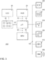
- Fig. 3 shows schematically a block diagram of the infotainment system 200 and, by way of example, some subsystems or applications of the infotainment system.
- the operating device comprises the touch-sensitive display unit 30, a computing device 40, an input unit 50 and a memory 60.
- the display unit 30 comprises both a display area for displaying variable graphic information and a user interface (touch-sensitive layer) arranged above the display area for entering commands by a User.
- the display unit 30 is connected to the computing device 40 via a data line 70.
- the data line can be designed according to the LVDS standard, corresponding to low voltage differential signaling.
- the display unit 30 receives control data for controlling the display surface of the touchscreen 30 from the computing device 40 via the data line 70. Control data of the commands entered are also transmitted from the touchscreen 30 to the computing device 40 via the data line 70.
- the input unit is denoted by the reference number 50. It includes the control elements already mentioned, such as buttons, rotary controls, slide controls or rotary push-button controls, with the help of which the operator can make entries via the menu navigation. Input is generally understood to mean the selection of a selected menu option, as well as changing a parameter, switching a function on and off, etc.
- the storage device 60 is connected to the computing device 40 via a data line 80.
- a pictogram directory and / or symbol directory with the pictograms and / or symbols for the possible insertion of additional information is stored in the memory 60.
- the points / symbols that serve as the basis for calculating the grid overlay can also be stored here.
- the other parts of the infotainment system camera 150, radio 140, navigation device 130, telephone 120 and instrument cluster 110 are connected to the device for operating the infotainment system via the data bus 100.
- the high-speed variant of the CAN bus according to ISO Standard 11898-2 can be used as the data bus 100.
- a bus system based on Ethernet technology such as BroadR-Reach could also be used.
- Bus systems in which data is transmitted via fiber optic cables can also be used.
- the camera 150 can be designed as a conventional video camera. In this case, it records 25 frames / s, which corresponds to 50 fields / s in the interlace recording mode.
- the vehicle 10 is equipped with a communication module 160 for wireless internal and external communication.
- This module is often referred to as an on-board unit. It can be designed for cellular communication, for example according to the LTE standard, corresponding to Long Term Evolution. It can also be designed for WLAN communication, corresponding to wireless LAN, be it for communication with devices of the occupants in the vehicle or for vehicle-to-vehicle communication, etc.
- the basis of the display according to the invention of the longitudinal guidance function of the vehicle 10 on the HUD 20 is the display of a virtual grid that is displayed at a distance above the actual road or without a distance from the road.
- the road is in the driver's field of vision as a real lane.
- the AR display by means of the HUD 20 is done as in Fig. 4 shown.
- the grid is projected in such a way that it lies on the street or "floats in space" at a distance from the street. It is shown that a grid is displayed along the course of the road. This extends to the vehicle in front. In the Fig. 4 it is shown that only the first section 310 of the grid is faded in at the time shown.
- the second section 320 of the grid is then faded in at a second point in time, see FIG. Fig. 5 .
- the first section 310 of the grid is already faded out again.
- the successive fading in of sections 310, 320 of the grid creates the impression for the driver of the vehicle 10 a “beacon” that moves from its vehicle 10 to the vehicle 300 in front.
- the impression created by the driver could also be described as a signal emanating from the own vehicle 10. Similar signaling is also found at construction sites on roadways, where the way to a bottleneck is marked by a control of "beacons", for example.
- the grid 22 could be divided into further sections which are displayed one after the other. This would make a more fluid movement of the guide beam visible.
- a driver assistance system is used for longitudinal guidance of the vehicle 10.
- Examples of such assistance systems are an automatic distance control ACC, corresponding to adaptive cruise control and a cruise control system GRA, corresponding to a cruise control system.
- the invention could also be used in the same way if the vehicle 10 were controlled fully automatically.
- the following describes which steps are undertaken when the vehicle 10 with an activated longitudinal guidance system, here an ACC system, approaches the vehicle 300 traveling ahead, detects it and adapts its speed to the vehicle 300 traveling ahead. This is done in such a way that a previously entered safety distance is observed.
- the longitudinal guidance system has already left the set-up mode and has switched to a control mode.
- the setup mode was visualized with the help of the beacon display.
- the change from the setup mode to the control mode is visualized as follows.
- the beacon display is exited and an AR overlay is calculated instead for the display of an object identification tag.
- even two object identification marks 330 and 335 are calculated.
- the detection mark 330 is calculated in such a way that it is displayed at the rear of the vehicle 300 traveling ahead and marks the rear of the vehicle 300 traveling ahead.
- the driver is thereby signaled relative to which vehicle the longitudinal guidance system regulates the distance and / or the speed.
- the second detection mark 335 is set at the end of the previously displayed grid. In the example it concerns both dog tags 330, 335 around diamond symbols. This procedure is intended to make the correct object perception understandable for the driver and to create the transparency of the technical processes necessary for building trust.
- a second AR overlay is calculated for the display of a regulation activity mark 340, which is intended to provide information on the regulation activity of the longitudinal guidance system.
- three diamond symbols are used as control activity mark 340, which are arranged differently depending on the control activity.
- Fig. 6 it is shown that the vehicle 10 is approaching the vehicle 300 in front. The instantaneous speed of the vehicle 300 in front is thus even lower than the setpoint speed entered in the observer vehicle 10, which in the illustrated case is also displayed in the driver's field of vision and is displayed at 30 km / h. The current speed is also displayed at 30 km / h. Both speeds are shown at the bottom of the screen. The current speed is displayed greater than the target speed.
- the regulation activity mark 340 has in Fig.
- FIG. 6 the shape of a forward arrow, also referred to as a "forward arrow".
- a forward arrow In the right picture of Fig. 6 a later point in time is shown. At this point in time, the observer vehicle 10 has moved closer to the vehicle traveling ahead. This is signaled to the driver by the fact that the control activity marker 335 is displayed closer to the vehicle 300 traveling ahead.
- the control activity marker 335 consists of three diamond symbols. If the two diamond symbols on the side are moved backwards compared to the middle diamond symbol, the aforementioned "forward arrow" is created.
- Three states are provided for the visualization of the control activity (as described above). If the system accelerates or if it approaches a vehicle in front due to an even higher set speed (reduction in distance), the forward arrow is used as an AR display. If the distance is kept constant, a line-like neutral symbol appears as an AR display. If the distance is increased because either a lower speed has been selected by the driver or a greater desired distance has been set, this is visualized by an arrow "backward arrow" directed towards the driver. In this case, from the driver's point of view, the regulation activity mark 340 is still “behind” the vehicle 300 traveling in front and then wanders “through” the vehicle traveling in front to the object mark 335.
- Fig. 7 the mentioned variants of a regulation activity mark 340 are shown.
- the "forward arrow” is shown in the left part of the picture.
- a corresponding “backward arrow” is in the right part of the Fig. 7 shown.
- “forward arrow” and “backward arrow” each consist of five diamond symbols.
- the neutral symbol is also shown, which is referred to below as the control lock symbol 350. It only consists of 3 diamond symbols arranged in a line.
- the displays described above do not have to be displayed permanently, but can also be hidden or displayed with significantly increased transparency.
- the longitudinal guidance system reduces the distance to the vehicle in front 300 until the set in the system or a calculated and calculated variable safety distance to the vehicle in front is reached.
- the AR overlay is calculated in such a way that when the middle diamond of the regulation activity mark 340 is congruent with the identification mark 335 displayed on the floor, the two rear diamonds of the regulation activity mark 340 are positioned to the front and are arranged on a line to the side of the middle diamond . As soon as the middle diamond ("arrowhead”) covers the identification tag ("snaps”), the repositioning of the side diamond symbols takes place. This procedure creates a “line” behind the vehicle 300 traveling in front, which follows the vehicle 300 traveling in front. This AR display informs the driver of the observer vehicle 10 that from now on the vehicle 10 will keep the distance from the vehicle 300 in front constant.
- Fig. 8 the moment in which the rule activity marker 340 just reaches the object marker 335 is shown.
- Fig. 9 shows the moment when a control lock symbol 350 has arisen from the forward arrow.
- a computer program for calculating the AR overlays is explained.
- the program is processed in the arithmetic unit 40.
- the start of the program is denoted by the reference number 405.
- a vehicle traveling ahead is detected in program step 410.
- the images supplied by the camera 150 are evaluated using the object recognition algorithms provided for this purpose.
- the grid is calculated for the section-wise AR overlay that follows.
- the grid is preferably calculated in perspective. The calculation continues to take place in such a way that the grid extends to the vehicle 300 in front.
- the 1st section of the calculated grid is then extracted in step 420.
- program step 425 the extracted data for the 1st section are transmitted to the head-up display 20.
- the program steps 430 and 435 relate to the extraction of the 2nd section of the calculated grid and the transmission of the extracted data to the HUD 20.
- the HUD 20 will then fade in the 2nd section of the grid.
- the successive fade-in of the 1st section and the 2nd section leads to the creation of the guide beam effect, which was described above.
- a loop is now formed in the program in which steps 415 to 435 are repeated 3 times.
- the program is then continued with program step 440.
- the calculation of the object marks 330, 335 and control activity mark 340 takes place therein.
- the calculation is carried out taking into account the current speed of the observer vehicle 10, the current speed of the preceding vehicle 300 and the calculated or set safety distance.
- the instantaneous speed of the vehicle traveling ahead can be estimated by continuously evaluating the images supplied by the camera 150.
- the current speed can be transmitted from the vehicle in front to the observer vehicle 300 via car-2-car communication.
- the data calculated for the AR display of the control activity mark 340 is transmitted to the HUD 20. Steps 440 and 445 again form a loop in the program that is run through until a change of state takes place. The change of state occurs when the regulation activity mark 340 has reached the object mark 335. So if the situation is as in Fig. 8 shown.
- the AR data for the control locking mark 350 are then calculated in the following program step 450. These data are then transmitted to the HUD 20 in program step 455. This then fades in the control detent mark 350, as in FIG Fig. 8 shown.
- the program steps 450 and 455 are then repeated continuously as long as the tracking of the preceding vehicle 300 continues at the set / calculated distance. If this state is exited, the program is ended in program step 460. If the driver intervenes and leaves the comfort function, the program can be ended at any time.
- specialty processors can include application specific integrated circuits (ASICs), reduced instruction set computers (RISC), and / or field programmable gate arrays (FPGAs).
- ASICs application specific integrated circuits
- RISC reduced instruction set computers
- FPGAs field programmable gate arrays
- the proposed method and the device are preferably implemented as a combination of hardware and software.
- the software is preferably installed as an application program on a program storage device. Typically, it is a computer platform-based machine that includes hardware such as one or more central processing units (CPU), random access memory (RAM), and one or more input / output (I / O) interfaces.
- An operating system is also typically installed on the computer platform.
- the various processes and functions described here may be part of the application program or a part that is executed by the operating system.
- the invention can always be used when the field of vision of a driver, an operator or simply a person with data glasses can be enhanced with AR overlays.
Landscapes
- Engineering & Computer Science (AREA)
- Physics & Mathematics (AREA)
- General Physics & Mathematics (AREA)
- Transportation (AREA)
- Mechanical Engineering (AREA)
- Automation & Control Theory (AREA)
- Combustion & Propulsion (AREA)
- Chemical & Material Sciences (AREA)
- Remote Sensing (AREA)
- Radar, Positioning & Navigation (AREA)
- Optics & Photonics (AREA)
- Theoretical Computer Science (AREA)
- Multimedia (AREA)
- Computer Graphics (AREA)
- Computer Hardware Design (AREA)
- General Engineering & Computer Science (AREA)
- Software Systems (AREA)
- Human Computer Interaction (AREA)
- Instrument Panels (AREA)
- Traffic Control Systems (AREA)
- Navigation (AREA)
Claims (9)
- Procédé de calcul d'une incrustation en AR, correspondant à une incrustation en « réalité augmentée », d'informations supplémentaires pour un affichage sur une unité d'affichage (20) d'un véhicule d'observateur (10) ou une paire de lunettes connectée, l'incrustation d'informations supplémentaires servant à des fins d'assistance au conducteur lors du guidage longitudinal du véhicule d'observateur (10), l'incrustation étant calculée à la manière de la « réalité augmentée », correspondant à la réalité étendue, de manière analogue à un contact avec un ou plusieurs objets dans l'environnement du véhicule d'observateur (10), la position d'un véhicule qui précède (300) étant détectée, un graphique d'animation étant calculé lors de l'ajustement de l'activité de régulation d'un système de guidage longitudinal pour le véhicule d'observateur (10) lors de l'approche du véhicule qui précède (300), caractérisé en ce que le graphique d'animation est calculé de telle sorte qu'à partir du véhicule d'observateur (10), le graphique d'animation est incrusté par portion, une incrustation en AR étant calculée lors de la première incrustation ou d'une incrustation récurrente de la fin du graphique d'animation de telle sorte qu'au moins un repère de reconnaissance d'objet (330, 335) est placé à la fin du véhicule qui précède (300) de manière analogue à un contact avec le véhicule qui précède (300), et
en vue de rendre reconnaissable une approche ou un éloignement par rapport au véhicule qui précède (300), un repère d'activité de régulation (340) est calculé, lequel est calculé de telle sorte que lors de l'approche par rapport au véhicule qui précède (300), il est incrusté sous la forme d'une flèche en direction du véhicule qui précède (300) entre le véhicule d'observateur (10) et le véhicule qui précède (300) et, en cas d'éloignement par rapport au véhicule qui précède (300), il est incrusté sous la forme d'une flèche à l'opposé du véhicule qui précède (300) entre le véhicule d'observateur (10) et le véhicule qui précède (300), le repère d'activité de régulation (340) étant calculé dans un système de guidage longitudinal destiné à réguler la distance ou à réguler la vitesse de telle sorte qu'il se déplace vers le véhicule qui précède lors d'une approche par rapport au véhicule qui précède (300),
lorsque la distance de consigne ou la vitesse de consigne est atteinte, le repère d'activité de régulation (340) étant calculé de telle sorte qu'il atteint la fin du graphique d'animation à la position du véhicule qui précède (300) et fusionne avec le repère de reconnaissance d'objet (335), au moins une partie latérale du repère d'activité de régulation (340) se déposant de manière analogue à un contact à côté du repère de reconnaissance d'objet (335). - Procédé selon la revendication 1, l'incrustation en AR étant calculée de telle sorte que deux repères de reconnaissance d'objet (330, 335) sont définis, un repère de reconnaissance d'objet (335) étant calculé de telle sorte qu'il repère la fin de la zone sur le sol derrière le véhicule et l'autre repère de reconnaissance d'objet (330) repère l'arrière du véhicule qui précède (300).
- Procédé selon l'une des revendications précédentes, le repère d'activité de régulation (340) étant calculé de telle sorte qu'il indique l'activité de régulation du système de guidage longitudinal, au moins deux états différents étant distingués, une flèche orientée dans le sens du déplacement étant formée lorsque la vitesse de consigne du système de guidage longitudinal est encore supérieure à la vitesse momentanée du véhicule d'observateur (300) ou la distance par rapport au véhicule qui précède (300) est encore supérieure à la distance de consigne, une flèche orientée vers l'arrière étant formée lorsque la vitesse de consigne du système de régulation de vitesse est inférieure à la vitesse momentanée du véhicule d'observateur (10) ou la distance par rapport au véhicule qui précède (300) est encore inférieure à la distance de consigne, et les parties latérales du repère d'activité de régulation (340) étant positionnées de telle sorte qu'un repère de verrouillage de régulation (350) de type ligne est formé lorsque la vitesse réelle coïncide avec la vitesse de consigne du système de régulation de vitesse ou la distance coïncide avec la distance de consigne.
- Procédé selon l'une des revendications précédentes, le graphique d'animation étant calculé sous la forme d'une grille composée d'une pluralité d'éléments de grille (305).
- Dispositif pour mettre en œuvre un procédé selon l'une des revendications précédentes, comprenant une unité d'affichage (20) avec laquelle des informations supplémentaires virtuelles peuvent être incrustées dans le champ de vision du conducteur ou de l'opérateur de l'objet, et une unité de calcul (40), le véhicule (10) possédant des moyens de détection (110, 150) qui détectent l'environnement du véhicule (10), l'unité de calcul (40) étant conçue pour calculer la position d'un véhicule qui précède (300) et pour calculer le mouvement du véhicule d'observateur (10) par rapport au véhicule qui précède (300), l'unité de calcul (40) étant conçue de manière à calculer un graphique d'animation lors de l'ajustement de l'activité de régulation d'un système de guidage longitudinal pour le véhicule d'observateur (10) lors de la reconnaissance d'une approche du véhicule qui précède (300), caractérisé en ce que le graphique d'animation est calculé de telle sorte qu'à partir du véhicule d'observateur (10), le graphique d'animation est incrusté par portion, une incrustation en AR étant calculée lors de la première incrustation ou d'une incrustation récurrente de la fin du graphique d'animation de telle sorte qu'au moins un repère de reconnaissance d'objet (330, 335) est placé à la fin du véhicule qui précède (300) de manière analogue à un contact avec le véhicule qui précède (300),
en vue de rendre reconnaissable une approche ou un éloignement par rapport au véhicule qui précède (300), l'unité de calcul (40) étant conçue de manière à calculer un repère d'activité de régulation (340) de telle sorte que lors de l'approche par rapport au véhicule qui précède (300), il est incrusté sous la forme d'une flèche en direction du véhicule qui précède (300) entre le véhicule d'observateur (10) et le véhicule qui précède (300) et, en cas d'éloignement par rapport au véhicule qui précède (300), il est incrusté sous la forme d'une flèche à l'opposé du véhicule qui précède (300) entre le véhicule d'observateur (10) et le véhicule qui précède (300), l'unité de calcul (40) dans un système de guidage longitudinal destiné à réguler la distance ou à réguler la vitesse étant conçue de manière à calculer le repère d'activité de régulation (340) de telle sorte qu'il se déplace vers le véhicule qui précède (300) lors d'une approche par rapport au véhicule qui précède (300),
et lorsque la distance de consigne ou la vitesse de consigne est atteinte, calculer le repère d'activité de régulation (340) de telle sorte qu'il atteint la fin du graphique d'animation à la position du véhicule qui précède (300) et fusionne avec le repère de reconnaissance d'objet (335), et au moins une partie latérale du repère d'activité de régulation (340) se dépose de manière analogue à un contact à côté du repère de reconnaissance d'objet (335). - Dispositif selon la revendication 5, l'unité de calcul (40) étant en outre conçue de manière à exécuter les calculs selon l'une des revendications 1 à 4.
- Dispositif selon la revendication 5 ou 6, l'unité d'affichage (20) étant un afficheur tête haute (HUD) ou une paire de lunettes connectées.
- Véhicule automobile, caractérisé en ce que le véhicule automobile (10) comporte un dispositif selon l'une des revendications 5 à 7.
- Programme informatique, caractérisé en ce que le programme informatique est conçu pour, lors de l'exécution dans une unité de calcul (40), mettre en œuvre les étapes du procédé de calcul d'une incrustation en AR d'informations supplémentaires pour un affichage sur une unité d'affichage (20) selon l'une des revendications 1 à 4.
Applications Claiming Priority (1)
| Application Number | Priority Date | Filing Date | Title |
|---|---|---|---|
| DE102018204254.3A DE102018204254B4 (de) | 2018-03-20 | 2018-03-20 | Verfahren zur Berechnung einer Einblendung von Zusatzinformationen für eine Anzeige auf einer Anzeigeeinheit, Vorrichtung zur Durchführung des Verfahrens sowie Kraftfahrzeug und Computerprogramm |
Publications (2)
| Publication Number | Publication Date |
|---|---|
| EP3543059A1 EP3543059A1 (fr) | 2019-09-25 |
| EP3543059B1 true EP3543059B1 (fr) | 2021-07-14 |
Family
ID=65443686
Family Applications (1)
| Application Number | Title | Priority Date | Filing Date |
|---|---|---|---|
| EP19157312.0A Active EP3543059B1 (fr) | 2018-03-20 | 2019-02-14 | Procédé de calcul d'une surimpression des informations supplémentaires pour un affichage sur une unité d'affichage, dispositif de mise en oeuvre du procédé, ainsi que véhicule automobile et programme informatique |
Country Status (6)
| Country | Link |
|---|---|
| US (1) | US10789490B2 (fr) |
| EP (1) | EP3543059B1 (fr) |
| KR (1) | KR102276096B1 (fr) |
| CN (1) | CN110304052B (fr) |
| DE (1) | DE102018204254B4 (fr) |
| ES (1) | ES2887103T3 (fr) |
Families Citing this family (15)
| Publication number | Priority date | Publication date | Assignee | Title |
|---|---|---|---|---|
| KR101803521B1 (ko) * | 2016-03-30 | 2017-11-30 | 지엠 글로벌 테크놀러지 오퍼레이션스 엘엘씨 | 차량용 인포테인먼트 시스템의 동작 제어 방법 |
| DE102018203462A1 (de) * | 2018-03-07 | 2019-09-12 | Volkswagen Aktiengesellschaft | Verfahren zur Berechnung einer Einblendung von Zusatzinformationen für eine Anzeige auf einer Anzeigeeinheit, Vorrichtung zur Durchführung des Verfahrens sowie Kraftfahrzeug und Computerprogramm |
| WO2020059926A1 (fr) * | 2018-09-21 | 2020-03-26 | 엘지전자 주식회사 | Terminal mobile et son procédé de commande |
| KR102116783B1 (ko) * | 2018-10-10 | 2020-05-29 | 네이버랩스 주식회사 | 영상을 지면에 위치시켜 운전자의 시점에 증강현실을 구현하는 3차원 증강현실 헤드업 디스플레이 |
| US11393197B2 (en) * | 2019-05-03 | 2022-07-19 | Cvent, Inc. | System and method for quantifying augmented reality interaction |
| DE102019206490B3 (de) * | 2019-05-06 | 2020-03-26 | Volkswagen Aktiengesellschaft | Parkassistenzsystem für ein Kraftfahrzeug, Verfahren zur Einparkunterstützung für ein Kraftfahrzeug, Computerprogramm und computerlesbares Speichermedium |
| EP4209401A4 (fr) * | 2020-09-02 | 2024-04-03 | Lg Electronics Inc | Système pour image d'écran ra de véhicule et procédé de fourniture de service d'image d'écran ra de véhicule |
| DE102020214843A1 (de) | 2020-11-26 | 2022-06-02 | Volkswagen Aktiengesellschaft | Verfahren zur Darstellung eines virtuellen Elements |
| JP2022126240A (ja) * | 2021-02-18 | 2022-08-30 | トヨタ自動車株式会社 | 車両用表示装置 |
| DE102021202246A1 (de) * | 2021-03-09 | 2022-09-15 | Volkswagen Aktiengesellschaft | Verbesserte Visualisierung mit einem AR HUD |
| KR20230005034A (ko) * | 2021-06-30 | 2023-01-09 | 현대자동차주식회사 | 자율 주행 차량, 그를 원격 제어하는 관제 시스템 및 그 방법 |
| FR3127165A1 (fr) | 2021-09-22 | 2023-03-24 | Psa Automobiles Sa | Procédé et dispositif d’aide à la conduite en réalité augmentée |
| JP2023054632A (ja) * | 2021-10-04 | 2023-04-14 | トヨタ自動車株式会社 | 車両用表示装置、車両、表示処理方法及びプログラム |
| CN113815415A (zh) * | 2021-10-12 | 2021-12-21 | 上海仙塔智能科技有限公司 | 驾驶引导的处理方法、装置、电子设备与存储介质 |
| CN114839782B (zh) * | 2022-06-07 | 2023-08-18 | 上汽大众汽车有限公司 | 一种用于车辆控制与信息显示的车载增强显示系统 |
Family Cites Families (24)
| Publication number | Priority date | Publication date | Assignee | Title |
|---|---|---|---|---|
| DE102011007329A1 (de) * | 2011-04-13 | 2012-10-18 | Robert Bosch Gmbh | Verfahren zum Betreiben eines Kraftfahrzeugs, Vorrichtung |
| DE102011082609A1 (de) * | 2011-09-13 | 2013-03-14 | Robert Bosch Gmbh | Verfahren und Vorrichtung zur Markierung eines relevanten Punktes |
| DE102011112943B4 (de) * | 2011-09-13 | 2020-08-27 | Volkswagen Aktiengesellschaft | Verfahren zum Bereitstellen eines Fahrerassistenzsystems mit automatischer Längsregelung für ein Fahrzeug und Fahrerassistenzsystem dazu |
| DE102011121763B4 (de) * | 2011-12-21 | 2023-04-06 | Volkswagen Aktiengesellschaft | Verfahren zur Darstellung einer Abstandsinformation auf einer Anzeigevorrichtung eines Fahrzeugs und Anzeigevorrichtung |
| US20150031448A1 (en) * | 2013-07-29 | 2015-01-29 | Edward Sekol | Rear mounted speedometer with panic deceleration and stopped vehicle warning device |
| EP2857247B1 (fr) * | 2013-10-01 | 2018-09-26 | Volkswagen Aktiengesellschaft | Procédé et dispositif pour un véhicule conçu pour le guidage longitudinal automatique |
| JP6481846B2 (ja) * | 2014-03-27 | 2019-03-13 | 日本精機株式会社 | 車両用警報装置 |
| JP6409337B2 (ja) | 2014-05-23 | 2018-10-24 | 日本精機株式会社 | 表示装置 |
| JP6149824B2 (ja) * | 2014-08-22 | 2017-06-21 | トヨタ自動車株式会社 | 車載装置、車載装置の制御方法及び車載装置の制御プログラム |
| DE102014113512A1 (de) * | 2014-09-18 | 2016-03-24 | E-Lead Electronic Co., Ltd. | Gerät zum gleichzeitigen Anzeigen von Navigations- und Fahrsicherheitsinformationen |
| JP6485732B2 (ja) * | 2014-12-10 | 2019-03-20 | 株式会社リコー | 情報提供装置、情報提供方法及び情報提供用制御プログラム |
| EP3031656B1 (fr) * | 2014-12-10 | 2018-01-03 | Ricoh Company, Ltd. | Dispositif et procédé de fourniture d'informations et support de stockage de programme de fourniture d'informations |
| JP6520668B2 (ja) * | 2015-02-09 | 2019-05-29 | 株式会社デンソー | 車両用表示制御装置及び車両用表示ユニット |
| JP6661883B2 (ja) * | 2015-02-09 | 2020-03-11 | 株式会社デンソー | 車両用表示制御装置及び車両用表示制御方法 |
| JP6642972B2 (ja) * | 2015-03-26 | 2020-02-12 | 修一 田山 | 車輌用画像表示システム及び方法 |
| DE112015006458B4 (de) * | 2015-04-17 | 2019-05-23 | Mitsubishi Electric Corporation | Anzeigesteuervorrichtung, Anzeigesystem, Anzeigesteuerverfahren und Anzeigesteuerprogramm |
| DE102015214761A1 (de) * | 2015-08-03 | 2017-02-09 | Volkswagen Aktiengesellschaft | Vorrichtung und Verfahren zur Unterstützung eines Führers eines Fortbewegungsmittels |
| BR112018006385B1 (pt) * | 2015-09-28 | 2022-07-05 | Nissan Motor Co., Ltd | Dispositivo de exibição veicular e método de exibição veicular |
| BR112018007120B1 (pt) * | 2015-10-09 | 2023-05-02 | Nissan Motor Co., Ltd | Dispositivo de display veicular e método de display veicular |
| JP2017105259A (ja) * | 2015-12-07 | 2017-06-15 | トヨタ自動車株式会社 | 車両用情報表示装置 |
| US10315566B2 (en) * | 2016-03-07 | 2019-06-11 | Lg Electronics Inc. | Vehicle control device mounted on vehicle and method for controlling the vehicle |
| US20170287217A1 (en) * | 2016-03-30 | 2017-10-05 | Kahyun Kim | Preceding traffic alert system and method |
| JP6861375B2 (ja) * | 2017-06-30 | 2021-04-21 | パナソニックIpマネジメント株式会社 | 表示システム、情報提示システム、表示システムの制御方法、プログラム、及び移動体 |
| KR102306790B1 (ko) * | 2017-11-08 | 2021-09-30 | 삼성전자주식회사 | 컨텐츠 시각화 장치 및 방법 |
-
2018
- 2018-03-20 DE DE102018204254.3A patent/DE102018204254B4/de not_active Expired - Fee Related
-
2019
- 2019-02-14 EP EP19157312.0A patent/EP3543059B1/fr active Active
- 2019-02-14 ES ES19157312T patent/ES2887103T3/es active Active
- 2019-03-16 US US16/355,736 patent/US10789490B2/en active Active
- 2019-03-20 KR KR1020190031847A patent/KR102276096B1/ko active IP Right Grant
- 2019-03-20 CN CN201910212171.3A patent/CN110304052B/zh active Active
Also Published As
| Publication number | Publication date |
|---|---|
| US10789490B2 (en) | 2020-09-29 |
| US20190294895A1 (en) | 2019-09-26 |
| ES2887103T3 (es) | 2021-12-21 |
| KR20190110482A (ko) | 2019-09-30 |
| DE102018204254A1 (de) | 2019-09-26 |
| CN110304052A (zh) | 2019-10-08 |
| EP3543059A1 (fr) | 2019-09-25 |
| DE102018204254B4 (de) | 2020-12-03 |
| KR102276096B1 (ko) | 2021-07-14 |
| CN110304052B (zh) | 2022-09-13 |
Similar Documents
| Publication | Publication Date | Title |
|---|---|---|
| EP3543059B1 (fr) | Procédé de calcul d'une surimpression des informations supplémentaires pour un affichage sur une unité d'affichage, dispositif de mise en oeuvre du procédé, ainsi que véhicule automobile et programme informatique | |
| DE102017221191B4 (de) | Verfahren zur Anzeige des Verlaufs einer Sicherheitszone vor einem Fahrzeug oder einem Objekt mit einer Anzeigeeinheit, Vorrichtung zur Durchführung des Verfahrens sowie Kraftfahrzeug und Computerprogramm | |
| WO2019170387A1 (fr) | Incrustation d'informations additionnelles sur une unité d'affichage | |
| DE102018203121B4 (de) | Verfahren zur Berechnung einer AR-Einblendung von Zusatzinformationen für eine Anzeige auf einer Anzeigeeinheit, Vorrichtung zur Durchführung des Verfahrens sowie Kraftfahrzeug und Computerprogramm | |
| DE102013200862B4 (de) | Optimaler Blickort an Anzeige für gesamte Frontscheibe | |
| DE102017212367B4 (de) | Vorrichtung zur Anzeige des Verlaufs einer Trajektorie vor einem Fahrzeug oder einem Objekt mit einer Anzeigeeinheit sowie Kraftfahrzeug | |
| EP3668742B1 (fr) | Procédé pour faire fonctionner un système d'aide à la conduite d'un véhicule à moteur et véhicule à moteur | |
| EP3425442B1 (fr) | Procédé d'enrichissement d'un champ de vision d'un conducteur d'un véhicule avec des informations additionnelles, dispositif d'utilisation dans un véhicule observateur, ainsi que véhicule automobile | |
| EP3717954B1 (fr) | Procédé d'affichage du déroulement d'une trajectoire devant un véhicule ou un objet pourvu d'une unité d'affichage, dispositif de mise en oeuvre du procédé | |
| WO2019228779A1 (fr) | Procédé de calcul d'une incrustation à réalité augmentée pour la représentation d'un itinéraire de navigation sur une unité d'affichage à réalité augmentée, dispositif servant à mettre en œuvre le procédé, ainsi que véhicule à moteur et programme informatique | |
| DE112017007631B4 (de) | Anzeigesystem und Anzeigeverfahren | |
| DE102019202581B4 (de) | Verfahren zum Betreiben eines Fahrerinformationssystems in einem Ego-Fahrzeug und Fahrerinformationssystem | |
| EP3569465A1 (fr) | Dispositif et système de fourniture d'une fonction d'automatisation pour un véhicule | |
| DE112019001620T5 (de) | Fahrassistenzsystem, Fahrassistenzvorrichtung und Fahrassistenzverfahren | |
| EP3269579A1 (fr) | Procede de fonctionnement d'un systeme d'informations et systeme d'informations | |
| WO2020173775A1 (fr) | Procédé pour faire fonctionner un système d'information du conducteur dans un égo-véhicule et système d'information du conducteur | |
| DE102012214829A1 (de) | Verfahren und Vorrichtung zum Darstellen einer Ausweichtrajektorie zur Kollisionsvermeidung für ein Fahrzeug | |
| DE102019215815A1 (de) | Fahrzeugsteuerungssystem und -verfahren | |
| EP3931030B1 (fr) | Procédé pour faire fonctionner un système d'information du conducteur dans un égo-véhicule et système d'information du conducteur | |
| EP3931025B1 (fr) | Procédé pour faire fonctionner un système d'information du conducteur dans un égo-véhicule et système d'information du conducteur | |
| DE102022209182A1 (de) | Anzeigeverfahren zur Darstellung eines virtuellen Umgebungsmodells, Computerprogramm, Rechenvorrichtung und Fahrzeug | |
| DE102020106851A1 (de) | Vorrichtung und Verfahren zur Unterstützung eines Fahrers eines Fahrzeugs bei einem Abbiege-Manöver |
Legal Events
| Date | Code | Title | Description |
|---|---|---|---|
| PUAI | Public reference made under article 153(3) epc to a published international application that has entered the european phase |
Free format text: ORIGINAL CODE: 0009012 |
|
| STAA | Information on the status of an ep patent application or granted ep patent |
Free format text: STATUS: THE APPLICATION HAS BEEN PUBLISHED |
|
| AK | Designated contracting states |
Kind code of ref document: A1 Designated state(s): AL AT BE BG CH CY CZ DE DK EE ES FI FR GB GR HR HU IE IS IT LI LT LU LV MC MK MT NL NO PL PT RO RS SE SI SK SM TR |
|
| AX | Request for extension of the european patent |
Extension state: BA ME |
|
| STAA | Information on the status of an ep patent application or granted ep patent |
Free format text: STATUS: REQUEST FOR EXAMINATION WAS MADE |
|
| 17P | Request for examination filed |
Effective date: 20200325 |
|
| RBV | Designated contracting states (corrected) |
Designated state(s): AL AT BE BG CH CY CZ DE DK EE ES FI FR GB GR HR HU IE IS IT LI LT LU LV MC MK MT NL NO PL PT RO RS SE SI SK SM TR |
|
| RIC1 | Information provided on ipc code assigned before grant |
Ipc: B60K 35/00 20060101AFI20201218BHEP Ipc: G02B 27/01 20060101ALI20201218BHEP Ipc: B60W 30/14 20060101ALI20201218BHEP |
|
| GRAP | Despatch of communication of intention to grant a patent |
Free format text: ORIGINAL CODE: EPIDOSNIGR1 |
|
| STAA | Information on the status of an ep patent application or granted ep patent |
Free format text: STATUS: GRANT OF PATENT IS INTENDED |
|
| INTG | Intention to grant announced |
Effective date: 20210209 |
|
| GRAJ | Information related to disapproval of communication of intention to grant by the applicant or resumption of examination proceedings by the epo deleted |
Free format text: ORIGINAL CODE: EPIDOSDIGR1 |
|
| STAA | Information on the status of an ep patent application or granted ep patent |
Free format text: STATUS: REQUEST FOR EXAMINATION WAS MADE |
|
| GRAP | Despatch of communication of intention to grant a patent |
Free format text: ORIGINAL CODE: EPIDOSNIGR1 |
|
| STAA | Information on the status of an ep patent application or granted ep patent |
Free format text: STATUS: GRANT OF PATENT IS INTENDED |
|
| INTC | Intention to grant announced (deleted) | ||
| INTG | Intention to grant announced |
Effective date: 20210413 |
|
| GRAS | Grant fee paid |
Free format text: ORIGINAL CODE: EPIDOSNIGR3 |
|
| GRAA | (expected) grant |
Free format text: ORIGINAL CODE: 0009210 |
|
| STAA | Information on the status of an ep patent application or granted ep patent |
Free format text: STATUS: THE PATENT HAS BEEN GRANTED |
|
| AK | Designated contracting states |
Kind code of ref document: B1 Designated state(s): AL AT BE BG CH CY CZ DE DK EE ES FI FR GB GR HR HU IE IS IT LI LT LU LV MC MK MT NL NO PL PT RO RS SE SI SK SM TR |
|
| REG | Reference to a national code |
Ref country code: GB Ref legal event code: FG4D Free format text: NOT ENGLISH |
|
| REG | Reference to a national code |
Ref country code: DE Ref legal event code: R096 Ref document number: 502019001797 Country of ref document: DE |
|
| REG | Reference to a national code |
Ref country code: IE Ref legal event code: FG4D Free format text: LANGUAGE OF EP DOCUMENT: GERMAN |
|
| REG | Reference to a national code |
Ref country code: AT Ref legal event code: REF Ref document number: 1410371 Country of ref document: AT Kind code of ref document: T Effective date: 20210815 |
|
| REG | Reference to a national code |
Ref country code: LT Ref legal event code: MG9D |
|
| REG | Reference to a national code |
Ref country code: NL Ref legal event code: MP Effective date: 20210714 |
|
| REG | Reference to a national code |
Ref country code: ES Ref legal event code: FG2A Ref document number: 2887103 Country of ref document: ES Kind code of ref document: T3 Effective date: 20211221 |
|
| PG25 | Lapsed in a contracting state [announced via postgrant information from national office to epo] |
Ref country code: NO Free format text: LAPSE BECAUSE OF FAILURE TO SUBMIT A TRANSLATION OF THE DESCRIPTION OR TO PAY THE FEE WITHIN THE PRESCRIBED TIME-LIMIT Effective date: 20211014 Ref country code: NL Free format text: LAPSE BECAUSE OF FAILURE TO SUBMIT A TRANSLATION OF THE DESCRIPTION OR TO PAY THE FEE WITHIN THE PRESCRIBED TIME-LIMIT Effective date: 20210714 Ref country code: PT Free format text: LAPSE BECAUSE OF FAILURE TO SUBMIT A TRANSLATION OF THE DESCRIPTION OR TO PAY THE FEE WITHIN THE PRESCRIBED TIME-LIMIT Effective date: 20211115 Ref country code: HR Free format text: LAPSE BECAUSE OF FAILURE TO SUBMIT A TRANSLATION OF THE DESCRIPTION OR TO PAY THE FEE WITHIN THE PRESCRIBED TIME-LIMIT Effective date: 20210714 Ref country code: BG Free format text: LAPSE BECAUSE OF FAILURE TO SUBMIT A TRANSLATION OF THE DESCRIPTION OR TO PAY THE FEE WITHIN THE PRESCRIBED TIME-LIMIT Effective date: 20211014 Ref country code: LT Free format text: LAPSE BECAUSE OF FAILURE TO SUBMIT A TRANSLATION OF THE DESCRIPTION OR TO PAY THE FEE WITHIN THE PRESCRIBED TIME-LIMIT Effective date: 20210714 Ref country code: SE Free format text: LAPSE BECAUSE OF FAILURE TO SUBMIT A TRANSLATION OF THE DESCRIPTION OR TO PAY THE FEE WITHIN THE PRESCRIBED TIME-LIMIT Effective date: 20210714 Ref country code: RS Free format text: LAPSE BECAUSE OF FAILURE TO SUBMIT A TRANSLATION OF THE DESCRIPTION OR TO PAY THE FEE WITHIN THE PRESCRIBED TIME-LIMIT Effective date: 20210714 Ref country code: FI Free format text: LAPSE BECAUSE OF FAILURE TO SUBMIT A TRANSLATION OF THE DESCRIPTION OR TO PAY THE FEE WITHIN THE PRESCRIBED TIME-LIMIT Effective date: 20210714 |
|
| PG25 | Lapsed in a contracting state [announced via postgrant information from national office to epo] |
Ref country code: PL Free format text: LAPSE BECAUSE OF FAILURE TO SUBMIT A TRANSLATION OF THE DESCRIPTION OR TO PAY THE FEE WITHIN THE PRESCRIBED TIME-LIMIT Effective date: 20210714 Ref country code: LV Free format text: LAPSE BECAUSE OF FAILURE TO SUBMIT A TRANSLATION OF THE DESCRIPTION OR TO PAY THE FEE WITHIN THE PRESCRIBED TIME-LIMIT Effective date: 20210714 Ref country code: GR Free format text: LAPSE BECAUSE OF FAILURE TO SUBMIT A TRANSLATION OF THE DESCRIPTION OR TO PAY THE FEE WITHIN THE PRESCRIBED TIME-LIMIT Effective date: 20211015 |
|
| REG | Reference to a national code |
Ref country code: DE Ref legal event code: R097 Ref document number: 502019001797 Country of ref document: DE |
|
| PG25 | Lapsed in a contracting state [announced via postgrant information from national office to epo] |
Ref country code: DK Free format text: LAPSE BECAUSE OF FAILURE TO SUBMIT A TRANSLATION OF THE DESCRIPTION OR TO PAY THE FEE WITHIN THE PRESCRIBED TIME-LIMIT Effective date: 20210714 |
|
| PLBE | No opposition filed within time limit |
Free format text: ORIGINAL CODE: 0009261 |
|
| STAA | Information on the status of an ep patent application or granted ep patent |
Free format text: STATUS: NO OPPOSITION FILED WITHIN TIME LIMIT |
|
| PG25 | Lapsed in a contracting state [announced via postgrant information from national office to epo] |
Ref country code: SM Free format text: LAPSE BECAUSE OF FAILURE TO SUBMIT A TRANSLATION OF THE DESCRIPTION OR TO PAY THE FEE WITHIN THE PRESCRIBED TIME-LIMIT Effective date: 20210714 Ref country code: SK Free format text: LAPSE BECAUSE OF FAILURE TO SUBMIT A TRANSLATION OF THE DESCRIPTION OR TO PAY THE FEE WITHIN THE PRESCRIBED TIME-LIMIT Effective date: 20210714 Ref country code: RO Free format text: LAPSE BECAUSE OF FAILURE TO SUBMIT A TRANSLATION OF THE DESCRIPTION OR TO PAY THE FEE WITHIN THE PRESCRIBED TIME-LIMIT Effective date: 20210714 Ref country code: EE Free format text: LAPSE BECAUSE OF FAILURE TO SUBMIT A TRANSLATION OF THE DESCRIPTION OR TO PAY THE FEE WITHIN THE PRESCRIBED TIME-LIMIT Effective date: 20210714 Ref country code: AL Free format text: LAPSE BECAUSE OF FAILURE TO SUBMIT A TRANSLATION OF THE DESCRIPTION OR TO PAY THE FEE WITHIN THE PRESCRIBED TIME-LIMIT Effective date: 20210714 |
|
| 26N | No opposition filed |
Effective date: 20220419 |
|
| PG25 | Lapsed in a contracting state [announced via postgrant information from national office to epo] |
Ref country code: IT Free format text: LAPSE BECAUSE OF FAILURE TO SUBMIT A TRANSLATION OF THE DESCRIPTION OR TO PAY THE FEE WITHIN THE PRESCRIBED TIME-LIMIT Effective date: 20210714 |
|
| PG25 | Lapsed in a contracting state [announced via postgrant information from national office to epo] |
Ref country code: MC Free format text: LAPSE BECAUSE OF FAILURE TO SUBMIT A TRANSLATION OF THE DESCRIPTION OR TO PAY THE FEE WITHIN THE PRESCRIBED TIME-LIMIT Effective date: 20210714 |
|
| REG | Reference to a national code |
Ref country code: CH Ref legal event code: PL |
|
| REG | Reference to a national code |
Ref country code: BE Ref legal event code: MM Effective date: 20220228 |
|
| PG25 | Lapsed in a contracting state [announced via postgrant information from national office to epo] |
Ref country code: LU Free format text: LAPSE BECAUSE OF NON-PAYMENT OF DUE FEES Effective date: 20220214 |
|
| PG25 | Lapsed in a contracting state [announced via postgrant information from national office to epo] |
Ref country code: LI Free format text: LAPSE BECAUSE OF NON-PAYMENT OF DUE FEES Effective date: 20220228 Ref country code: IE Free format text: LAPSE BECAUSE OF NON-PAYMENT OF DUE FEES Effective date: 20220214 Ref country code: CH Free format text: LAPSE BECAUSE OF NON-PAYMENT OF DUE FEES Effective date: 20220228 |
|
| PG25 | Lapsed in a contracting state [announced via postgrant information from national office to epo] |
Ref country code: BE Free format text: LAPSE BECAUSE OF NON-PAYMENT OF DUE FEES Effective date: 20220228 |
|
| PGFP | Annual fee paid to national office [announced via postgrant information from national office to epo] |
Ref country code: FR Payment date: 20230223 Year of fee payment: 5 |
|
| P01 | Opt-out of the competence of the unified patent court (upc) registered |
Effective date: 20230523 |
|
| PGFP | Annual fee paid to national office [announced via postgrant information from national office to epo] |
Ref country code: ES Payment date: 20240308 Year of fee payment: 6 |
|
| PG25 | Lapsed in a contracting state [announced via postgrant information from national office to epo] |
Ref country code: MK Free format text: LAPSE BECAUSE OF FAILURE TO SUBMIT A TRANSLATION OF THE DESCRIPTION OR TO PAY THE FEE WITHIN THE PRESCRIBED TIME-LIMIT Effective date: 20210714 Ref country code: CY Free format text: LAPSE BECAUSE OF FAILURE TO SUBMIT A TRANSLATION OF THE DESCRIPTION OR TO PAY THE FEE WITHIN THE PRESCRIBED TIME-LIMIT Effective date: 20210714 |
|
| PGFP | Annual fee paid to national office [announced via postgrant information from national office to epo] |
Ref country code: DE Payment date: 20240229 Year of fee payment: 6 Ref country code: CZ Payment date: 20240202 Year of fee payment: 6 Ref country code: GB Payment date: 20240220 Year of fee payment: 6 |