EP3542544B1 - Gewebenetzelement für ein gehäuse für einen elektroakustischen treiber, entsprechendes gehäuse, lautsprecher und gehäuseelement - Google Patents
Gewebenetzelement für ein gehäuse für einen elektroakustischen treiber, entsprechendes gehäuse, lautsprecher und gehäuseelement Download PDFInfo
- Publication number
- EP3542544B1 EP3542544B1 EP17811351.0A EP17811351A EP3542544B1 EP 3542544 B1 EP3542544 B1 EP 3542544B1 EP 17811351 A EP17811351 A EP 17811351A EP 3542544 B1 EP3542544 B1 EP 3542544B1
- Authority
- EP
- European Patent Office
- Prior art keywords
- enclosure
- mesh
- woven mesh
- woven
- mesh element
- Prior art date
- Legal status (The legal status is an assumption and is not a legal conclusion. Google has not performed a legal analysis and makes no representation as to the accuracy of the status listed.)
- Active
Links
Images


Classifications
-
- H—ELECTRICITY
- H04—ELECTRIC COMMUNICATION TECHNIQUE
- H04R—LOUDSPEAKERS, MICROPHONES, GRAMOPHONE PICK-UPS OR LIKE ACOUSTIC ELECTROMECHANICAL TRANSDUCERS; ELECTRIC HEARING AIDS; PUBLIC ADDRESS SYSTEMS
- H04R1/00—Details of transducers, loudspeakers or microphones
- H04R1/02—Casings; Cabinets ; Supports therefor; Mountings therein
- H04R1/023—Screens for loudspeakers
-
- H—ELECTRICITY
- H04—ELECTRIC COMMUNICATION TECHNIQUE
- H04R—LOUDSPEAKERS, MICROPHONES, GRAMOPHONE PICK-UPS OR LIKE ACOUSTIC ELECTROMECHANICAL TRANSDUCERS; ELECTRIC HEARING AIDS; PUBLIC ADDRESS SYSTEMS
- H04R1/00—Details of transducers, loudspeakers or microphones
- H04R1/20—Arrangements for obtaining desired frequency or directional characteristics
- H04R1/22—Arrangements for obtaining desired frequency or directional characteristics for obtaining desired frequency characteristic only
- H04R1/28—Transducer mountings or enclosures modified by provision of mechanical or acoustic impedances, e.g. resonator, damping means
- H04R1/2807—Enclosures comprising vibrating or resonating arrangements
- H04R1/2815—Enclosures comprising vibrating or resonating arrangements of the bass reflex type
- H04R1/2819—Enclosures comprising vibrating or resonating arrangements of the bass reflex type for loudspeaker transducers
-
- H—ELECTRICITY
- H04—ELECTRIC COMMUNICATION TECHNIQUE
- H04R—LOUDSPEAKERS, MICROPHONES, GRAMOPHONE PICK-UPS OR LIKE ACOUSTIC ELECTROMECHANICAL TRANSDUCERS; ELECTRIC HEARING AIDS; PUBLIC ADDRESS SYSTEMS
- H04R1/00—Details of transducers, loudspeakers or microphones
- H04R1/20—Arrangements for obtaining desired frequency or directional characteristics
- H04R1/22—Arrangements for obtaining desired frequency or directional characteristics for obtaining desired frequency characteristic only
- H04R1/30—Combinations of transducers with horns, e.g. with mechanical matching means, i.e. front-loaded horns
-
- H—ELECTRICITY
- H04—ELECTRIC COMMUNICATION TECHNIQUE
- H04R—LOUDSPEAKERS, MICROPHONES, GRAMOPHONE PICK-UPS OR LIKE ACOUSTIC ELECTROMECHANICAL TRANSDUCERS; ELECTRIC HEARING AIDS; PUBLIC ADDRESS SYSTEMS
- H04R9/00—Transducers of moving-coil, moving-strip, or moving-wire type
- H04R9/06—Loudspeakers
-
- H—ELECTRICITY
- H04—ELECTRIC COMMUNICATION TECHNIQUE
- H04R—LOUDSPEAKERS, MICROPHONES, GRAMOPHONE PICK-UPS OR LIKE ACOUSTIC ELECTROMECHANICAL TRANSDUCERS; ELECTRIC HEARING AIDS; PUBLIC ADDRESS SYSTEMS
- H04R2499/00—Aspects covered by H04R or H04S not otherwise provided for in their subgroups
- H04R2499/10—General applications
Definitions
- the present invention relates to an electroacoustic driver housing element in the form of a woven mesh element and in particular to a speaker or sounder comprising an enclosure employing such an element, and one that can be arranged for operation within a hazardous area.
- Sound output devices such as speakers and sounders are commonly employed within, for example, industrial and/or processing environments comprising hazardous areas and environments.
- Such areas and environments include in particular those where there is the danger of explosion due for example to the possible presence of explosive gases, and in particular explosive dust.
- Explosive dust environments are particularly dangerous since dust explosions tend to be much more powerful than gas explosions for a given volume.
- an electroacoustic driver unit is present so as to provide for audible sounds/signals such as for communication and/or alarm purposes.
- the electroacoustic driver unit is provided in a housing offering a sufficient degree of sealing so as to prevent any potentially explosive event occurring within the housing travelling to the hazardous area/environment within which the housing is located.
- the protection concept for a gas atmosphere is to allow the gas into the enclosure but then prevent any internal explosion propagating to the outside atmosphere.
- the protection concept for an explosive dust atmosphere is to prevent any dust ingress into the enclosure since it is not currently possible to construct practical enclosures strong enough to contain dust explosions.
- One form of speaker or sounder arranged for use within a hazardous area employs a sintered material to seal the housing and which, while allowing an audible signal to pass through, provides a sufficient degree of isolation to prevent any explosive event within the housing travelling into the hazardous area/environment.
- the sintered element While allowing the required sound to be output into the area/environment, the sintered element nevertheless serves to attenuate the sound output from the driver thereby limiting the effective volume of its output. Also, such sintered elements commonly allow for water ingress and, if insufficiently dense, can also allow for dust ingress making such known driver units unsuitable for explosive dust-laden atmospheres.
- a balance has to be struck between a requirement for a low density sinter for sound output and as against a minimum density requirement to effectively quench a flame arising from an explosive event within the housing and so as to prevent it propagating into the external explosive-atmosphere.
- a further known complication is that for explosive dust environments, the density of the sinter element should be increased further so as to prevent the ingress of dust into the enclosure. As a consequence of this, loud speaker/sounder housings that are certified for use within explosive dust environments will typically offer a lower sound output for any given power rating.
- sintered elements for electroacoustic driver housings can comprise a layered structure employing several layers of an industry standard cross-woven metal mesh insofar as this is found to provide a good balance between flame quenching and porosity to sound, particularly insofar as the gas volume behind the sinter element is limited.
- sound output is attenuated by -1dB relative to the sinter being absent. While the level of attenuation is therefore attractive for such known woven metal mesh sinters, such structures are however not considered suitable for use in explosive dust environments and atmospheres, in particular since they are insufficiently dense to prevent ingress of dust.
- the present invention therefore seeks to provide an electroacoustic driver housing element arranged to allow for a sufficient level of sound output while offering the required degree of safety for operation in explosive environments and in particular those where explosive dust might be present.
- WO 2014/035571 A1 discloses a portable electronic device having an outer case having a planar face in which a microphone associated acoustic port is formed.
- the device also has a micro-electro-mechanical system (MEMS) microphone positioned within the outer case, the MEMS microphone having a diaphragm facing the microphone associated acoustic port.
- MEMS micro-electro-mechanical system
- An acoustic mesh is positioned between the front face of the outer case and the diaphragm, the acoustic mesh having a non-linear acoustic resistance.
- US 2009/245565 A1 discloses a portable electronic device having acoustic ports such as microphone and speaker ports. Acoustic devices such as microphones and speakers may be associated with the acoustic ports.
- An acoustic port may have an opening between an interior and exterior of the portable electronic device. The opening may be covered by a metal mesh. An acoustic fabric may be interposed between the metal mesh and the opening. The opening may be formed from a hole in a glass member having outer and inner chambers.
- a microphone boot may be provided that forms front and rear radial seals with a housing of the device and a microphone unit respectively. The microphone boot may also form multiple face seals with the microphone unit.
- a speaker for the speaker port may be enclosed in a sealed speaker enclosure. The speaker enclosure may have a pressure-equalizing vent slit covered with an acoustic mesh.
- WO 2009/134591 A1 discloses an acoustic apparatus including an acoustic driver, acoustically coupled to a pipe to radiate acoustic energy into the pipe.
- the pipe includes an elongated opening along at least a portion of the length of the pipe through which acoustic energy is radiated to the environment.
- US 2009/060246 A1 discloses an acoustic sensor system including a housing structure, and a miniaturized acoustic transducer mounted in the housing structure.
- a flame arrestor structure is mounted on or within the housing structure between the acoustic transducer and the external environment, so that ambient acoustic energy passes through the flame arrestor structure before reaching the acoustic transducer.
- WO 2010/004285 A1 discloses a speaker assembly including a housing for enclosing an internal space from an external environment.
- a movable body is arranged in the external environment and configured to generate audible sound waves when moved suitably.
- a first magnetic element is coupled to the movable body and a second magnetic element is capable of interacting with the first magnetic element to cause the movable body to move, wherein at least one of the first and second magnetic elements including an electromagnet.
- Each electromagnet is sealed from the external environment by at least a portion of the housing.
- the housing is configurable to seal the internal space from the external environment, and each electromagnet is sealed from the external environment by at least a portion of the housing.
- EP 0 582 740 A1 discloses a method of fabricating a gas-permeable, metallic cover for a pressure-resistant casing intended for accommodating electrical operating media. A multiplicity of slots through which the gas can penetrate are made in the cover.
- GB 1268446 A discloses a multilayer knitted wire mesh component for acoustic attenuation applications and made of sintered Dutch twill.
- KR 2016 0047530 A discloses a protective mesh for sound ports made of polymeric material formed as monofilament Dutch-type closed mesh.
- a woven mesh element for an electroacoustic driver enclosure, the element comprising a plurality of mesh layers, and wherein the said plurality includes a layer of Dutch weave mesh, said woven mesh element being configured to cover a sound opening of said enclosure.
- the present invention is advantageous insofar as it allows for an increase in sound output from electroacoustic drivers employed within hazardous environments and atmospheres, such as hazardous area horns and speakers, and which can be certified for use in hazardous dust environments but while providing improved sound attenuation figures as compared with the current art.
- An advantage of the present invention is that it covers the aspects required by both gas and dust protection concepts, and so can provide a standard product that can meet both requirements with little compromise on sound output.
- the present invention allows for the provision of a combination of wire mesh types, sintered together to form a flame arrester which can readily comply with the requirements of hazardous dust environment standards, without the elements porosity to sound being unduly compromised.
- the layer of Dutch weave mesh can comprise a layer of Dutch twill weave mesh.
- the mesh layers best comprise woven wire mesh layers.
- at least one of the plurality of mesh layers comprises a layer of cross woven mesh.
- a particularly advantageous configuration of the present invention can comprise a multi-layered element comprising a plurality of layers of cross weave mesh and a single layer of Dutch weave mesh.
- the layer of Dutch weave mesh can be provided as an outer layer of the element, whereas in another example, the layer of Dutch weave mesh can comprise an inner layer of the said element.
- aspects of the present invention provide for a sintered metal element employing the structure as defined above and also an electroacoustic driver housing including an element such as defined above.
- the housing can advantageously be arranged for providing use in flame-proof and/or explosion-proof characteristics.
- a loud speaker or sounder can be provided including such a housing as defined above.
- the present invention provides for an electroacoustic-driver-enclosure element comprising a plurality of mesh layers, and wherein the said plurality includes a layer of Dutch weave mesh.
- a single layer of, for example industry standard Dutch weave mesh it is found to be effective at preventing the ingress of dust due, in particular, to the shape of the pores presented by the Dutch weave mesh.
- the housing element of the present invention would be suitable for use in relation to all hazardous area gas groups. This has the particular advantage that a common driver/sounder/loud-speaker device can be provided meet both requirements.
- a sounder/speaker assembly 10 comprising a housing 12 enclosing an internal volume 14 in which there is located an electroacoustic driver 16 comprising a relatively large permanent magnetic 18, a voice coil 20 mounted to a diaphragm 22.
- the driver and diaphragm are arranged to supply, in response to an audio signal at the positive/negative terminals 23, audible sound waves arranged to exit the housing 12 by way of an opening 24.
- a frusto-conical outer horn 26 serving to acoustically couple the output audible signal.
- a flat disk-like sintered metal element 28 is provided and serving to close the opening 24 and offer the required isolation between the enclosure internal volume 14 and the hazardous environment external to the housing 12.
- the sintered metal element 28 is provided to quench a flame of an internal explosion and comprises a metal mesh sinter.
- the sound waves created by the driver 16 can however pass through this sintered element 28 and onward via the outer horn 26 although a degree of attenuation occurs at the sintered element 28. Such attenuation can, to some extent, be compensated for by an overly large and expensive driver 16 and associated magnet 18.
- the sintered element 28 comprises a plurality of layers of wire mesh 28A sintered together so as to form the sintered element 28 and, as required by the present invention, employing as one of the layers, a layer of Dutch weave mesh.
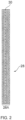
- Fig. 2 there is provided a sectional view of the sintered element 28 employed within the housing 12 of Fig. 1 and which, as noted, comprises a plurality of wire mesh layers 28A sintered together.
- the multi-layered sintered element 28 includes a single layer 30 of Dutch weave mesh which in the illustrated example comprises a single layer of industry standard Dutch twill weave 30 ⁇ 250 uM mesh, 0.0075' wire diameter, which can also be referred to as micromesh.
- the remaining (9 in the illustrated example) layers are each formed of industry standard cross weave wire mesh, which in the illustrated example can comprise 60 ⁇ 60 uM mesh, 0.0075' wire diameter.
- the layer of Dutch twill weave mesh is provided within the body, and generally within a central region, of the multi-layered sintered element 28.
- the single layer 32 of Dutch twill weave mesh is provided on, and forming part of an outer surface of the sintered element 28.
- the element of the present invention proves advantageous insofar as it can prevent the ingress of dust due to the presence of the layer of Dutch twill weave mesh thereby meeting the required standards for explosive dust hazardous areas.
- the remainder of the sinter element is provided by layers of industry standard cross weave wire mesh the overall porosity to sound of the sintered element 28 is limited only to a minor, and readily acceptable, degree.
- the overall layered structure therefore acts an effective flame arrester for explosive gas atmospheres, while being sufficiently porous to sound, but with the added feature of preventing the ingress of dust as noted above.
- the combination of mesh types as employed within the present invention therefore provides for a sintered element offering sufficient porosity to sound along with effective flame arrester capabilities and while preventing the ingress of dust when located in explosive dust environments.
- the sintered element can be formed of any required number of layers of mesh material which could comprise two or more different types of mesh.
- more than one layer of Dutch twill woven mesh could be provided within the sintered element 28 and the overall shape and configuration of the sintered element is in no way restricted to that as illustrated in the accompanying drawings.
- reference to a loudspeaker and sounder are intended to encompass an electroacoustic transducer-based device for outputting any form of audible sound wave or signal.
Landscapes
- Physics & Mathematics (AREA)
- Engineering & Computer Science (AREA)
- Acoustics & Sound (AREA)
- Signal Processing (AREA)
- Health & Medical Sciences (AREA)
- Otolaryngology (AREA)
- Details Of Audible-Bandwidth Transducers (AREA)
Claims (14)
- Gewebenetzelement (28) für ein Gehäuse (12) für einen elektroakustischen Treiber (16), wobei das Gewebenetzelement (28) eine Vielzahl von miteinander versinterten Netzschichten umfasst, wobei die Vielzahl von Netzschichten eine Schicht aus Tressengewebenetz enthält, wobei das Gewebenetzelement (28) dadurch gekennzeichnet ist, dass es dazu ausgestaltet ist, eine Schallöffnung (24) des Gehäuses (12) abzudecken.
- Gewebenetzelement (28) nach Anspruch 1, wobei die Schicht aus Tressengewebenetz eine Schicht aus Köpertressengewebenetz umfasst.
- Gewebenetzelement (28) nach Anspruch 1 oder 2, wobei die Vielzahl von Netzschichten Schichten aus Drahtgewebenetz umfasst.
- Gewebenetzelement (28) nach Anspruch 1, 2 oder 3, wobei das Gewebenetzelement (28) ein Metallnetz umfasst.
- Gewebenetzelement (28) nach einem oder mehreren der vorhergehenden Ansprüche, wobei die Vielzahl der Netzschichten eine Schicht aus kreuzverwobenem Netz enthält.
- Gewebenetzelement (28) nach Anspruch 5, wobei das Gewebenetzelement (28) eine Vielzahl von Schichten aus kreuzverwobenem Netz enthält.
- Gewebenetzelement (28) nach Anspruch 6, wobei das Gewebenetzelement (28) eine einzelne Schicht aus Tressengewebenetz umfasst.
- Gewebenetzelement (28) nach einem oder mehreren der vorhergehenden Ansprüche, wobei die Schicht aus Tressengewebe eine äußere Schicht des Gewebenetzelements (28) umfasst.
- Gewebenetzelement (28) nach einem oder mehreren der Ansprüche 1 bis 7, wobei die Schicht aus Tressengewebe eine innere Schicht des Gewebenetzelements (28) umfasst.
- Gewebenetzelement (28) nach einem oder mehreren der vorhergehenden Ansprüche, wobei das Gewebenetzelement (28) einen Flammenschutz umfasst.
- Gehäuse (12) für einen elektroakustischen Treiber (16), wobei das Gehäuse (12) das Gewebenetzelement (28) nach einem oder mehreren der vorhergehenden Ansprüche enthält.
- Gehäuse (12) nach Anspruch 11, wobei das Gehäuse (12) feuer- und/oder explosionssicher ist.
- Lautsprecher oder Schallgeber (10), der das Gehäuse (12) nach Anspruch 11 oder 12 enthält.
- Element eines Gehäuses (12) eines elektroakustischen Treibers (16), der das Gewebenetzelement (28) nach einem der Ansprüche 1 bis 10 umfasst.
Applications Claiming Priority (2)
| Application Number | Priority Date | Filing Date | Title |
|---|---|---|---|
| GBGB1619517.4A GB201619517D0 (en) | 2016-11-18 | 2016-11-18 | Electroacoustic driver housing element |
| PCT/GB2017/053436 WO2018091887A1 (en) | 2016-11-18 | 2017-11-15 | Electroacoustic driver housing element |
Publications (2)
| Publication Number | Publication Date |
|---|---|
| EP3542544A1 EP3542544A1 (de) | 2019-09-25 |
| EP3542544B1 true EP3542544B1 (de) | 2025-01-01 |
Family
ID=57993890
Family Applications (1)
| Application Number | Title | Priority Date | Filing Date |
|---|---|---|---|
| EP17811351.0A Active EP3542544B1 (de) | 2016-11-18 | 2017-11-15 | Gewebenetzelement für ein gehäuse für einen elektroakustischen treiber, entsprechendes gehäuse, lautsprecher und gehäuseelement |
Country Status (4)
| Country | Link |
|---|---|
| US (1) | US11490180B2 (de) |
| EP (1) | EP3542544B1 (de) |
| GB (1) | GB201619517D0 (de) |
| WO (1) | WO2018091887A1 (de) |
Families Citing this family (2)
| Publication number | Priority date | Publication date | Assignee | Title |
|---|---|---|---|---|
| JP7041966B2 (ja) * | 2019-11-06 | 2022-03-25 | 株式会社宮木電機製作所 | 防爆音響機器 |
| CN116233702A (zh) * | 2023-01-31 | 2023-06-06 | 广州市声讯电子科技股份有限公司 | 一种防爆强声器 |
Citations (2)
| Publication number | Priority date | Publication date | Assignee | Title |
|---|---|---|---|---|
| GB1268446A (en) * | 1968-05-27 | 1972-03-29 | Pall Corp | Anisometric compressed and bonded multilayer knitted wire mesh composites |
| KR20160047530A (ko) * | 2013-08-26 | 2016-05-02 | 사아티 에스.피.에이. | 자기장 방호 및 차폐 다층 직물 구조 |
Family Cites Families (16)
| Publication number | Priority date | Publication date | Assignee | Title |
|---|---|---|---|---|
| US3432002A (en) * | 1967-05-01 | 1969-03-11 | Ltv Ling Altec Inc | Horn-loaded loudspeaker |
| DE3312318A1 (de) * | 1983-04-06 | 1984-10-11 | Neumann Elektronik GmbH, 4330 Mülheim | Explosionsgeschuetzter elektroakustischer wandler |
| GB9202865D0 (en) * | 1992-02-12 | 1992-03-25 | East Anglian Electronics | Loudspeakers |
| EP0582740A1 (de) | 1992-08-12 | 1994-02-16 | MARCO SYSTEMANALYSE UND ENTWICKLUNG GmbH | Verfahren zur Herstellung einer gasdurchlässigen metallischen Abdeckung eines Schlagwettergeschützten, druckfesten Gehäuses |
| GB2319105A (en) * | 1996-11-07 | 1998-05-13 | Signature Ind Ltd | An alarm device |
| KR100638512B1 (ko) * | 2005-10-14 | 2006-10-25 | 주식회사 비에스이 | 금속 메쉬 위상지연소자와 이를 구비하는 콘덴서마이크로폰 |
| KR100673843B1 (ko) * | 2005-10-31 | 2007-01-24 | 주식회사 비에스이 | 윈드 스크린 필터를 구비하는 콘덴서 마이크로폰과 이콘덴서 마이크로폰이 실장되는 외부프레임 |
| US8792658B2 (en) | 2007-08-30 | 2014-07-29 | General Monitors, Inc. | Techniques for protection of acoustic devices |
| US8055003B2 (en) * | 2008-04-01 | 2011-11-08 | Apple Inc. | Acoustic systems for electronic devices |
| US8351630B2 (en) * | 2008-05-02 | 2013-01-08 | Bose Corporation | Passive directional acoustical radiating |
| US7938223B2 (en) * | 2008-05-21 | 2011-05-10 | Cooper Technologies Company | Sintered elements and associated systems |
| GB2461867B (en) | 2008-07-11 | 2010-09-22 | Cooper Medc Ltd | Speaker assembly |
| CN202617202U (zh) * | 2012-06-21 | 2012-12-19 | 乐清市华熙防爆电器有限公司 | 防爆电话机 |
| US8724841B2 (en) * | 2012-08-30 | 2014-05-13 | Apple Inc. | Microphone with acoustic mesh to protect against sudden acoustic shock |
| CN204013691U (zh) * | 2014-07-08 | 2014-12-10 | 深圳市西骏科技有限公司 | 一种防爆电话机 |
| US9794661B2 (en) * | 2015-08-07 | 2017-10-17 | Knowles Electronics, Llc | Ingress protection for reducing particle infiltration into acoustic chamber of a MEMS microphone package |
-
2016
- 2016-11-18 GB GBGB1619517.4A patent/GB201619517D0/en not_active Ceased
-
2017
- 2017-11-15 US US16/461,965 patent/US11490180B2/en active Active
- 2017-11-15 EP EP17811351.0A patent/EP3542544B1/de active Active
- 2017-11-15 WO PCT/GB2017/053436 patent/WO2018091887A1/en not_active Ceased
Patent Citations (2)
| Publication number | Priority date | Publication date | Assignee | Title |
|---|---|---|---|---|
| GB1268446A (en) * | 1968-05-27 | 1972-03-29 | Pall Corp | Anisometric compressed and bonded multilayer knitted wire mesh composites |
| KR20160047530A (ko) * | 2013-08-26 | 2016-05-02 | 사아티 에스.피.에이. | 자기장 방호 및 차폐 다층 직물 구조 |
Also Published As
| Publication number | Publication date |
|---|---|
| US20190327546A1 (en) | 2019-10-24 |
| WO2018091887A1 (en) | 2018-05-24 |
| US11490180B2 (en) | 2022-11-01 |
| GB201619517D0 (en) | 2017-01-04 |
| EP3542544A1 (de) | 2019-09-25 |
Similar Documents
| Publication | Publication Date | Title |
|---|---|---|
| US10567858B2 (en) | Loudspeaker module and terminal device | |
| US10034073B2 (en) | Device having a composite acoustic membrane | |
| EP1998591B1 (de) | Tauchfähige Lautsprecheranordnung | |
| US8194907B2 (en) | Wind filter for use with a microphone | |
| JP2018514135A (ja) | デュアルダイアフラムマイクロホン | |
| EP3967055B1 (de) | Headset und/oder gehörschutzvorrichtung mit einer wasserdichten lautsprecheranordnung mit dekompression | |
| JP2013526172A (ja) | 音響部品を形成するための繊維積層構造 | |
| NO131744B (de) | ||
| US12439188B2 (en) | Micro-electro-mechanical systems (MEMS) microphone assembly | |
| CN112913256B (zh) | 双层麦克风保护 | |
| CN114866631B (zh) | 电子设备 | |
| US11490180B2 (en) | Electroacoustic driver housing element | |
| CN212963448U (zh) | 一种组合传感器装置和终端电子设备 | |
| WO2009071896A1 (en) | Apparatus for accurate ambient noise sensing and reduction in the presence of wind | |
| EP3542551B1 (de) | Elektro-akustische ansteuerung und zugehöriger lautsprecher/echolot | |
| CN212278463U (zh) | 一种扬声器和终端设备 | |
| EP3977752B1 (de) | Techniken zur windgeräuschverminderung | |
| EP4085650B1 (de) | Kabelloser kopfhörer mit verbesserter widerstandsfähigkeit gegen windgeräusche | |
| JP4451917B2 (ja) | 携帯機器、音響部品配置方法、及び音響部品アセンブリ | |
| US20180027317A1 (en) | Closed acoustical architecture having a controlled leakage | |
| CN101449592B (zh) | 电机声学换能器的安装结构 | |
| CN218734957U (zh) | 麦克风及电子设备 | |
| WO2025236242A1 (en) | Earphone | |
| CN114157971A (zh) | 一种扬声器和终端设备 | |
| JP2013183261A (ja) | 電気音響変換装置を備えた電子機器 |
Legal Events
| Date | Code | Title | Description |
|---|---|---|---|
| STAA | Information on the status of an ep patent application or granted ep patent |
Free format text: STATUS: UNKNOWN |
|
| STAA | Information on the status of an ep patent application or granted ep patent |
Free format text: STATUS: THE INTERNATIONAL PUBLICATION HAS BEEN MADE |
|
| PUAI | Public reference made under article 153(3) epc to a published international application that has entered the european phase |
Free format text: ORIGINAL CODE: 0009012 |
|
| STAA | Information on the status of an ep patent application or granted ep patent |
Free format text: STATUS: REQUEST FOR EXAMINATION WAS MADE |
|
| 17P | Request for examination filed |
Effective date: 20190611 |
|
| AK | Designated contracting states |
Kind code of ref document: A1 Designated state(s): AL AT BE BG CH CY CZ DE DK EE ES FI FR GB GR HR HU IE IS IT LI LT LU LV MC MK MT NL NO PL PT RO RS SE SI SK SM TR |
|
| AX | Request for extension of the european patent |
Extension state: BA ME |
|
| DAV | Request for validation of the european patent (deleted) | ||
| DAX | Request for extension of the european patent (deleted) | ||
| STAA | Information on the status of an ep patent application or granted ep patent |
Free format text: STATUS: EXAMINATION IS IN PROGRESS |
|
| 17Q | First examination report despatched |
Effective date: 20210712 |
|
| P01 | Opt-out of the competence of the unified patent court (upc) registered |
Effective date: 20230521 |
|
| GRAP | Despatch of communication of intention to grant a patent |
Free format text: ORIGINAL CODE: EPIDOSNIGR1 |
|
| STAA | Information on the status of an ep patent application or granted ep patent |
Free format text: STATUS: GRANT OF PATENT IS INTENDED |
|
| GRAC | Information related to communication of intention to grant a patent modified |
Free format text: ORIGINAL CODE: EPIDOSCIGR1 |
|
| RIC1 | Information provided on ipc code assigned before grant |
Ipc: H04R 9/06 20060101ALN20240627BHEP Ipc: H04R 1/30 20060101ALN20240627BHEP Ipc: H04R 1/02 20060101AFI20240627BHEP |
|
| INTG | Intention to grant announced |
Effective date: 20240704 |
|
| RIN1 | Information on inventor provided before grant (corrected) |
Inventor name: KENDRICK, JOHN ROBBERT Inventor name: COATES, DAVID ANDREW |
|
| GRAS | Grant fee paid |
Free format text: ORIGINAL CODE: EPIDOSNIGR3 |
|
| GRAA | (expected) grant |
Free format text: ORIGINAL CODE: 0009210 |
|
| STAA | Information on the status of an ep patent application or granted ep patent |
Free format text: STATUS: THE PATENT HAS BEEN GRANTED |
|
| AK | Designated contracting states |
Kind code of ref document: B1 Designated state(s): AL AT BE BG CH CY CZ DE DK EE ES FI FR GB GR HR HU IE IS IT LI LT LU LV MC MK MT NL NO PL PT RO RS SE SI SK SM TR |
|
| REG | Reference to a national code |
Ref country code: GB Ref legal event code: FG4D |
|
| REG | Reference to a national code |
Ref country code: DE Ref legal event code: R096 Ref document number: 602017087117 Country of ref document: DE |
|
| REG | Reference to a national code |
Ref country code: CH Ref legal event code: EP |
|
| REG | Reference to a national code |
Ref country code: IE Ref legal event code: FG4D |
|
| REG | Reference to a national code |
Ref country code: LT Ref legal event code: MG9D |
|
| REG | Reference to a national code |
Ref country code: NL Ref legal event code: MP Effective date: 20250101 |
|
| REG | Reference to a national code |
Ref country code: AT Ref legal event code: MK05 Ref document number: 1757526 Country of ref document: AT Kind code of ref document: T Effective date: 20250101 |
|
| PG25 | Lapsed in a contracting state [announced via postgrant information from national office to epo] |
Ref country code: NL Free format text: LAPSE BECAUSE OF FAILURE TO SUBMIT A TRANSLATION OF THE DESCRIPTION OR TO PAY THE FEE WITHIN THE PRESCRIBED TIME-LIMIT Effective date: 20250101 |
|
| PG25 | Lapsed in a contracting state [announced via postgrant information from national office to epo] |
Ref country code: FI Free format text: LAPSE BECAUSE OF FAILURE TO SUBMIT A TRANSLATION OF THE DESCRIPTION OR TO PAY THE FEE WITHIN THE PRESCRIBED TIME-LIMIT Effective date: 20250101 |
|
| PG25 | Lapsed in a contracting state [announced via postgrant information from national office to epo] |
Ref country code: PL Free format text: LAPSE BECAUSE OF FAILURE TO SUBMIT A TRANSLATION OF THE DESCRIPTION OR TO PAY THE FEE WITHIN THE PRESCRIBED TIME-LIMIT Effective date: 20250101 |
|
| PG25 | Lapsed in a contracting state [announced via postgrant information from national office to epo] |
Ref country code: ES Free format text: LAPSE BECAUSE OF FAILURE TO SUBMIT A TRANSLATION OF THE DESCRIPTION OR TO PAY THE FEE WITHIN THE PRESCRIBED TIME-LIMIT Effective date: 20250101 |
|
| PG25 | Lapsed in a contracting state [announced via postgrant information from national office to epo] |
Ref country code: IS Free format text: LAPSE BECAUSE OF FAILURE TO SUBMIT A TRANSLATION OF THE DESCRIPTION OR TO PAY THE FEE WITHIN THE PRESCRIBED TIME-LIMIT Effective date: 20250501 |
|
| PG25 | Lapsed in a contracting state [announced via postgrant information from national office to epo] |
Ref country code: HR Free format text: LAPSE BECAUSE OF FAILURE TO SUBMIT A TRANSLATION OF THE DESCRIPTION OR TO PAY THE FEE WITHIN THE PRESCRIBED TIME-LIMIT Effective date: 20250101 |
|
| PG25 | Lapsed in a contracting state [announced via postgrant information from national office to epo] |
Ref country code: LV Free format text: LAPSE BECAUSE OF FAILURE TO SUBMIT A TRANSLATION OF THE DESCRIPTION OR TO PAY THE FEE WITHIN THE PRESCRIBED TIME-LIMIT Effective date: 20250101 Ref country code: PT Free format text: LAPSE BECAUSE OF FAILURE TO SUBMIT A TRANSLATION OF THE DESCRIPTION OR TO PAY THE FEE WITHIN THE PRESCRIBED TIME-LIMIT Effective date: 20250502 |
|
| PG25 | Lapsed in a contracting state [announced via postgrant information from national office to epo] |
Ref country code: BG Free format text: LAPSE BECAUSE OF FAILURE TO SUBMIT A TRANSLATION OF THE DESCRIPTION OR TO PAY THE FEE WITHIN THE PRESCRIBED TIME-LIMIT Effective date: 20250101 Ref country code: GR Free format text: LAPSE BECAUSE OF FAILURE TO SUBMIT A TRANSLATION OF THE DESCRIPTION OR TO PAY THE FEE WITHIN THE PRESCRIBED TIME-LIMIT Effective date: 20250402 |
|
| PG25 | Lapsed in a contracting state [announced via postgrant information from national office to epo] |
Ref country code: AT Free format text: LAPSE BECAUSE OF FAILURE TO SUBMIT A TRANSLATION OF THE DESCRIPTION OR TO PAY THE FEE WITHIN THE PRESCRIBED TIME-LIMIT Effective date: 20250101 |
|
| PG25 | Lapsed in a contracting state [announced via postgrant information from national office to epo] |
Ref country code: CZ Free format text: LAPSE BECAUSE OF FAILURE TO SUBMIT A TRANSLATION OF THE DESCRIPTION OR TO PAY THE FEE WITHIN THE PRESCRIBED TIME-LIMIT Effective date: 20250101 |
|
| PG25 | Lapsed in a contracting state [announced via postgrant information from national office to epo] |
Ref country code: SE Free format text: LAPSE BECAUSE OF FAILURE TO SUBMIT A TRANSLATION OF THE DESCRIPTION OR TO PAY THE FEE WITHIN THE PRESCRIBED TIME-LIMIT Effective date: 20250101 |
|
| REG | Reference to a national code |
Ref country code: DE Ref legal event code: R097 Ref document number: 602017087117 Country of ref document: DE |
|
| PG25 | Lapsed in a contracting state [announced via postgrant information from national office to epo] |
Ref country code: SM Free format text: LAPSE BECAUSE OF FAILURE TO SUBMIT A TRANSLATION OF THE DESCRIPTION OR TO PAY THE FEE WITHIN THE PRESCRIBED TIME-LIMIT Effective date: 20250101 |
|
| PG25 | Lapsed in a contracting state [announced via postgrant information from national office to epo] |
Ref country code: DK Free format text: LAPSE BECAUSE OF FAILURE TO SUBMIT A TRANSLATION OF THE DESCRIPTION OR TO PAY THE FEE WITHIN THE PRESCRIBED TIME-LIMIT Effective date: 20250101 |
|
| PG25 | Lapsed in a contracting state [announced via postgrant information from national office to epo] |
Ref country code: IT Free format text: LAPSE BECAUSE OF FAILURE TO SUBMIT A TRANSLATION OF THE DESCRIPTION OR TO PAY THE FEE WITHIN THE PRESCRIBED TIME-LIMIT Effective date: 20250101 |
|
| PG25 | Lapsed in a contracting state [announced via postgrant information from national office to epo] |
Ref country code: EE Free format text: LAPSE BECAUSE OF FAILURE TO SUBMIT A TRANSLATION OF THE DESCRIPTION OR TO PAY THE FEE WITHIN THE PRESCRIBED TIME-LIMIT Effective date: 20250101 |
|
| PG25 | Lapsed in a contracting state [announced via postgrant information from national office to epo] |
Ref country code: RO Free format text: LAPSE BECAUSE OF FAILURE TO SUBMIT A TRANSLATION OF THE DESCRIPTION OR TO PAY THE FEE WITHIN THE PRESCRIBED TIME-LIMIT Effective date: 20250101 |
|
| PG25 | Lapsed in a contracting state [announced via postgrant information from national office to epo] |
Ref country code: SK Free format text: LAPSE BECAUSE OF FAILURE TO SUBMIT A TRANSLATION OF THE DESCRIPTION OR TO PAY THE FEE WITHIN THE PRESCRIBED TIME-LIMIT Effective date: 20250101 |
|
| PLBE | No opposition filed within time limit |
Free format text: ORIGINAL CODE: 0009261 |
|
| STAA | Information on the status of an ep patent application or granted ep patent |
Free format text: STATUS: NO OPPOSITION FILED WITHIN TIME LIMIT |
|
| 26N | No opposition filed |
Effective date: 20251002 |
|
| PGFP | Annual fee paid to national office [announced via postgrant information from national office to epo] |
Ref country code: DE Payment date: 20251022 Year of fee payment: 9 |
|
| PGFP | Annual fee paid to national office [announced via postgrant information from national office to epo] |
Ref country code: GB Payment date: 20251023 Year of fee payment: 9 |
|
| PGFP | Annual fee paid to national office [announced via postgrant information from national office to epo] |
Ref country code: NO Payment date: 20251024 Year of fee payment: 9 |