EP3541259B2 - Haushaltsreinigungsbehälter und anordnung mit solch einem behälter und einem wischmopp - Google Patents
Haushaltsreinigungsbehälter und anordnung mit solch einem behälter und einem wischmopp Download PDFInfo
- Publication number
- EP3541259B2 EP3541259B2 EP17803833.7A EP17803833A EP3541259B2 EP 3541259 B2 EP3541259 B2 EP 3541259B2 EP 17803833 A EP17803833 A EP 17803833A EP 3541259 B2 EP3541259 B2 EP 3541259B2
- Authority
- EP
- European Patent Office
- Prior art keywords
- cleaning liquid
- basin
- tank
- container
- cleaning
- Prior art date
- Legal status (The legal status is an assumption and is not a legal conclusion. Google has not performed a legal analysis and makes no representation as to the accuracy of the status listed.)
- Active
Links
Images


Classifications
-
- A—HUMAN NECESSITIES
- A47—FURNITURE; DOMESTIC ARTICLES OR APPLIANCES; COFFEE MILLS; SPICE MILLS; SUCTION CLEANERS IN GENERAL
- A47L—DOMESTIC WASHING OR CLEANING; SUCTION CLEANERS IN GENERAL
- A47L13/00—Implements for cleaning floors, carpets, furniture, walls, or wall coverings
- A47L13/10—Scrubbing; Scouring; Cleaning; Polishing
- A47L13/50—Auxiliary implements
- A47L13/51—Storing of cleaning tools, e.g. containers therefor
-
- A—HUMAN NECESSITIES
- A47—FURNITURE; DOMESTIC ARTICLES OR APPLIANCES; COFFEE MILLS; SPICE MILLS; SUCTION CLEANERS IN GENERAL
- A47L—DOMESTIC WASHING OR CLEANING; SUCTION CLEANERS IN GENERAL
- A47L13/00—Implements for cleaning floors, carpets, furniture, walls, or wall coverings
- A47L13/10—Scrubbing; Scouring; Cleaning; Polishing
- A47L13/20—Mops
-
- A—HUMAN NECESSITIES
- A47—FURNITURE; DOMESTIC ARTICLES OR APPLIANCES; COFFEE MILLS; SPICE MILLS; SUCTION CLEANERS IN GENERAL
- A47L—DOMESTIC WASHING OR CLEANING; SUCTION CLEANERS IN GENERAL
- A47L13/00—Implements for cleaning floors, carpets, furniture, walls, or wall coverings
- A47L13/10—Scrubbing; Scouring; Cleaning; Polishing
- A47L13/50—Auxiliary implements
- A47L13/51—Storing of cleaning tools, e.g. containers therefor
- A47L13/512—Clamping devices for hanging the tools
Definitions
- the present invention relates to a cleaning tub intended for household cleaning of any type of smooth surface, in particular floors.
- the present invention also relates to an assembly comprising such a bin and a broom.
- a bucket filled with a cleaning liquid for example water mixed, if necessary, with a cleaning product or detergent.
- a cleaning liquid for example water mixed, if necessary, with a cleaning product or detergent.
- the user dips a mop in the cleaning liquid before applying it to the floor to scrub the floor with said mop.
- the mop is again dipped in the liquid contained in the bucket in order to be rinsed and then wrung out before being dipped again to clean a new portion of the floor.
- the user repeats the operation as many times as necessary to clean the desired floor surface.
- these operations lead to the cleaning liquid being gradually contaminated with dirt taken from the floor to be cleaned. This results in frequent replacement of the cleaning liquid and overconsumption of water and cleaning product.
- Multi-compartment buckets comprising a cleaning liquid tank and a dirty water vessel, the latter topped with a wringing device.
- these devices do not prevent contamination of the clean liquid tank because the dirt is still present on the mop, so that some of it is nevertheless diluted in the clean liquid tank when the mop is immersed in the tank in order to be rinsed or soaked to clean a new portion of the floor.
- the document EP0781524 discloses a dosing device which aims to limit the consumption of cleaning liquid.
- the dosing device comprises a reserve chamber containing the cleaning liquid and a wetting chamber in which a cleaning tool is immersed in the cleaning liquid.
- the cleaning liquid is introduced in a controlled manner via a dosing valve and an actuating member acting on said valve, from the reserve chamber to the wetting chamber.
- the invention aims to provide a cleaning device that reduces water consumption and cleaning product consumption. It also aims to avoid or at least reduce contamination of the cleaning liquid each time the mop is immersed in the device after use on a floor, improving hygiene. It also aims to facilitate the use of a cleaning device. It aims to provide a more economical and more ecological device. Finally, it aims to provide a more reliable and more compact cleaning device.
- At least one of the objectives is achieved with a bin as defined in claim 1.
- the invention is based on Pascal's principle which characterizes the equilibrium of liquids.
- the cleaning liquid (of uniform density) is in equilibrium between the cleaning liquid reservoir and the basin.
- the surface of the cleaning liquid contained in the basin is always subjected to atmospheric pressure, while the surface of the cleaning liquid contained in the reservoir is subjected to a lower pressure due to the airtightness of the reservoir.
- the at least one opening is not submerged on the basin side, it allows air to enter the reservoir and consequently the cleaning liquid contained in the reservoir. flows into the basin, until the liquid level in the basin closes the opening again.
- the level of cleaning liquid is substantially constant in the basin while it decreases regularly in the reservoir, as the reservoir refills the basin after each withdrawal from the basin.
- the liquid always moves from the reservoir to the basin, so that any dirt brought back by the spongy body does not contaminate the reservoir, which therefore always supplies the basin with perfectly clean liquid.
- the permanent communication between the basin and the reservoir is a guarantee of reliability, compared to the prior art.
- the capacity of cleaning liquid in the basin corresponds to a quantity just sufficient to properly soak the spongy body. Overconsumption of cleaning liquid is also controlled or avoided, as is the risk that residual dirt, after wringing, mixes with a large quantity of liquid, which improves hygiene during cleaning.
- the cleaning tank has a generally rectangular exterior shape.
- the basin has a generally rectangular or quadrilateral interior shape so that the spongy body can rest on the surface of the bottom of the basin.
- the cleaning tub according to the invention is intended to be used, typically, with a broom comprising a spongy body on or around the head of the broom.
- the broom comprises a head of substantially rectangular or quadrilateral shape such that said head is surrounded at least in part by the spongy body.
- the spongy body is a mop or a wipe.
- the shape of the head of the broom is sized so that the head can rest on the surface of the bottom of the basin in a sort of nesting in the basin.
- the broom comprises a head of substantially cylindrical shape on which are arranged fringes constituting the spongy body.
- This type of broom is called a mop.
- the length of the fringes is chosen so that they can all be inserted into the basin.
- the cleaning tray is also intended to be used with a sponge, a wipe or one of the devices, provided with a spongy body, mentioned above and provided with a handle so that the tray is also easy to use for cleaning table or window surfaces.
- the cleaning liquid reservoir and the basin are juxtaposed.
- the bottom of the cleaning liquid reservoir is at the same level as the bottom of the basin so that the cleaning liquid flows freely from the reservoir to the basin.
- the bottom of the cleaning liquid reservoir and the bottom of the basin are made in one piece, constituting a lower wall of the cleaning tank.
- the cleaning liquid tank may be partly located above the basin, for example separated by several centimeters.
- a main cleaning liquid tank is connected to an intermediate tank, of very small capacity compared to the main tank, via a pipe.
- the intermediate tank is separated from the basin by the partition having the at least one opening.
- the partition having the at least one opening may have any geometric shape, for example rectangular, polygonal, cylindrical or conical and be inclined at a non-zero angle relative to the bottom of the basin.
- the at least one opening forms a tunnel between the cleaning fluid reservoir and the basin.
- the at least one opening is permanently open.
- Perfectly open means an opening or passage free of any part, or set of parts connected together, passing through the opening and projecting on either side of the partition, said part or set of parts extending in a direction normal to the plane in which the at least one opening is formed and being arranged and configured to obstruct said opening.
- "permanently open” means an opening without obstruction of the valve type.
- the cleaning fluid reservoir is airtight when the at least one opening is submerged in cleaning fluid.
- the partition is angularly inclined at an angle of between 45 and 90 degrees relative to the horizontal.
- the at least one opening is arranged and configured to provide an air intake for the cleaning liquid tank when the tank is suitably tilted relative to the cleaning position, in the direction placing the at least one opening in the high position.
- the cleaning liquid tank is filled by pouring cleaning liquid into the basin, then tilting the tank so that the liquid flows into the tank via the at least one opening.
- the tank is inclined angularly by approximately 30 degrees relative to the horizontal.
- the tank can be inclined at an angle of between 1 and 90 degrees relative to the horizontal.
- the cleaning tank can be gradually inclined in order to provide a continuous air intake, via the at least one opening, to fill the tank as much as possible. The tilt allows the air present in the cleaning liquid tank to escape during filling.
- the tank is tilted so that the surface of the cleaning liquid reaches the level of the at least one opening.
- the cleaning liquid flows into the basin, via the at least one opening, until the at least one opening is submerged.
- an air pocket of pressure lower than atmospheric pressure is created between the upper wall of the tank, constituting the ceiling of said tank, and the surface of the cleaning liquid in the tank.
- an additional air intake is made on one face of the basin, separating the cleaning liquid tank and the basin, to facilitate the filling of the cleaning liquid tank, this air intake being submerged in the cleaning position or closable by a plug or a valve.
- the height of the at least one opening corresponds substantially to the height of the level of cleaning liquid in the basin.
- the level of cleaning liquid in the basin corresponds substantially to the level necessary to submerge the at least one opening.
- the height of the at least one opening is preferably between 1 and 15 millimeters relative to the bottom of the basin, in particular between 3 and 5 millimeters.
- This embodiment of the tank is preferred for use with a mop head provided with a wipe.
- the height of the at least one opening is preferably between 10 and 15 millimeters.
- This embodiment of the tank is preferred for use with a mop head provided with fringes.
- the height of the at least one opening can be up to 20 millimeters.
- This height of liquid in the basin allows the spongy body surrounding the mop to be sufficiently soaked to allow cleaning of the floor and saves cleaning liquid, generally water and/or detergent or cleaning product(s). In this way, contamination of the liquid present in the basin is also avoided because the head of the mop is not immersed, the liquid impregnating the mop by capillarity.
- the bottom of the tank can be hollowed out, forming a cavity, from one to several millimeters deep, directly above each opening.
- the cavities make it possible to increase the passage section of the cleaning liquid from the openings when filling the cleaning liquid tank. This feature makes it easier to fill the cleaning liquid tank, particularly when the height of the opening is low.
- the creation of the cavities does not change the height of the cleaning liquid level in the basin.
- the cleaning tank preferably includes a waste liquid collection chamber.
- the collection chamber is used to receive the waste liquid present in the spongy body of the mop before moistening it again in the basin.
- the waste liquid collection chamber and the cleaning liquid reservoir are separated by a single wall. This feature makes it possible to provide a compact cleaning tank.
- the cleaning liquid reservoir comprises a reduced section area forming a passage for the cleaning liquid between the cleaning liquid reservoir and the basin.
- the passage is located near a side opposite an outlet of the collection chamber.
- said passage communicates with the at least one opening arranged in the partition separating the basin from the cleaning liquid reservoir, said partition extending in a direction transverse to the tank.
- the tank comprises a cavity, forming an antechamber, located between the cleaning liquid reservoir and the basin.
- the cavity is provided between the partition having the at least one opening and a retention partition extending towards a first longitudinal side of the tank but leaving a passage, corresponding to the reduced section area, between the end of the retention partition and the inner face of the first longitudinal side.
- the outlet of the collection chamber is provided through a second longitudinal side of the tank which is opposite the first longitudinal side.
- the tank can be tilted towards the second longitudinal side which places the passage in the high position and allows the used liquid collection chamber to be emptied while preventing the leakage or spillage of the cleaning liquid contained in the tank thanks to the retention partition.
- This also allows the water from the basin to quickly return to the tank when the tank is tilted in a vertical position, so that the basin is located above the cleaning liquid reservoir in a vertical position.
- the tank preferably comprises a wringing zone having at least one scraper, arranged and configured to allow the spongy body, for example the spongy body surrounding the mop, to be rubbed therein.
- the wringing zone allows the waste liquid soaking the spongy body to be evacuated.
- the wringing zone comprises ribs.
- the ribs may be arranged in a V shape.
- the wringing zone has the shape of a cylinder projecting from the upper face of the cleaning tank, when the latter is in the cleaning position.
- the wringing zone comprises a cone-shaped cavity arranged in the cylinder, the cone widening upwards.
- the surface of the cone has ribs, arranged and configured to allow a spongy body of the type comprising fringes, for example a mop, to be rubbed thereon.
- the mop is preferably wrung out on the wringing zone by applying the head of the mop having the fringes against the ribs and rotating the mop so that the fringes rub against the ribs.
- the wringing zone communicates with the waste liquid collection chamber.
- the wringing zone is located on an inclined plane such that the waste liquid flows by gravity into the collection chamber.
- the waste liquid flows by gravity into a cavity, constituting the collection chamber, juxtaposed with the wringing zone.
- the cavity is entirely open on top.
- the collection chamber is located below the wringing zone so that the collection chamber is partially covered on top.
- the upper wall of the tank corresponds to a separation between the wringing zone and the collection chamber; the upper surface of said wall constituting the wringing zone, and the lower surface of said wall the ceiling of the collection chamber when the tank is in the cleaning position.
- the upper wall has a discharge orifice for the used liquid.
- the discharge orifice is arranged and configured so that the used liquid present on the wringing zone flows by gravity towards the collection chamber.
- the upper wall of the tank is substantially concave and inclined so that the water flows by gravity towards the discharge orifice.
- the wringing zone is located both above the collection chamber and the cleaning liquid reservoir. This feature makes it possible to provide a compact cleaning tank.
- the tank comprises a device for adjusting the height of the at least one opening in order to adjust the level of cleaning liquid in the basin.
- the adjustment device is a plate extending longitudinally, forming a strip, arranged parallel to the partition.
- the strip is arranged and configured to translate in height and parallel to the partition.
- the transverse partition has, on one of its faces, a device for guiding the strip, such as grooves, to guide the translation of the strip.
- the strip comprises a sealing lip arranged and configured to bear on the face of the partition in order to allow the height of the at least one opening to be adjusted. This feature makes it possible to vary the height of the at least one opening by 1 to 20 millimeters. This feature makes it possible to enlarge the section of the at least one opening and makes it easier to fill the tank with cleaning liquid.
- the tank comprises a vase for household cleaning product or detergent, arranged and configured to diffuse cleaning product or detergent into the basin.
- the vase is placed between the cleaning liquid reservoir and the basin.
- the vase is placed on a side wall of the basin but without touching the bottom of the basin.
- the vase comprises, at its base, orifices of very small sections arranged on the bottom or on a side face near the bottom thereof, so as to diffuse the cleaning product into the basin.
- said vase is removable to facilitate its filling.
- the cleaning product is solid and diffuses by erosion when the user introduces water into the vase.
- the tank is arranged and configured to be placed on the ground in an upright position in which the basin is located above the cleaning liquid tank and the at least one opening is in a high position relative to the cleaning liquid tank.
- the upright position corresponds to a substantially vertical position.
- the outlet of the collection chamber and the discharge orifice are positioned in the upper part of the collection chamber when the tank is in a substantially vertical position. The outlet of the collection chamber and the discharge orifice are positioned relative to the tank to prevent the used liquid from escaping when the tank is in a substantially vertical position.
- the tank has on its periphery an oblique transverse face which constitutes the lower face in the upright position. In this way, the tank automatically tilts to rest against a vertical wall such as a wall when the tank is placed on the floor in the upright position along this wall. This feature facilitates the storage of the cleaning tank.
- the bin comprises a hanging device near the basin.
- Said hanging device is arranged and configured to allow the bin to be suspended without the tank or the used liquid collection chamber being able to empty.
- the hanging device is arranged and configured to cooperate with at least one hook fixed to the handle of a broom so that the bin can be stored by being suspended by means of the broom, itself suspended or placed on the ground, or the bin being placed vertically on the ground and against a wall with the broom engaged by means of the hook.
- this allows the bin to be raised using the broom without the user having to bend down.
- the tank is made in one piece so that it forms a single piece.
- a cleaning tank is compact.
- the tank comprises at least the cleaning liquid reservoir, the basin, the transverse partition comprising the at least one opening, and where appropriate the used liquid collection chamber and/or the wringing zone having at least one scraper.
- the retention partition can also be made in one piece with the tray.
- the tray is manufactured by an extrusion blow molding method.
- some elements can be added to the “single” part, for example the detergent vase, for example by sliding in and snapping in.
- the cleaning liquid reservoir is removable. This feature facilitates filling of the reservoir. In this embodiment, the cleaning liquid pours into the bottom of the tank.
- the tub includes non-slip pads arranged under the bottom of the tub.
- the non-slip pads are arranged and configured to limit slippage between the tub and the floor when the tub is in the cleaning position, in particular when scraping the spongy body on the wringing area.
- a location for the user's foot may be provided on the tub, so that the user can press the tub on the floor in order to limit slippage between the tub and the floor when the tub is in the cleaning position, in particular when scraping the spongy body on the wringing area.
- the cleaning liquid tank preferably has a capacity of at least 1 liter. According to other particular embodiments, the cleaning liquid tank can contain up to 5 liters of cleaning liquid.
- the used liquid collection chamber can also be removable, in particular to facilitate emptying.
- an assembly comprising a tub, intended for household cleaning according to one or more of the preceding characteristics, and a broom arranged and configured to cooperate with said tub.
- the tub and the broom each comprise a hooking device arranged and configured to simultaneously place the tub and the broom in the storage position.
- the tub comprises a hooking bar such as an eyelet arranged and configured to cooperate with a hooking device of the broom.
- the broom comprises at least one hook arranged and configured to cooperate with the hooking bar or the eyelet of the cleaning tub.
- the assembly comprises a broom whose head has a contour which fits with little play into the internal contour of the basin.
- the assembly can also comprise a mop.
- FIG. 1 illustrates a cleaning tank 1 intended to receive cleaning liquid in particular for cleaning smooth floors, for example tiles or parquet.
- the tank is used with a broom 100 comprising a handle 102 and a head 101 provided with a spongy body 104, said spongy body being intended to absorb the cleaning liquid from the cleaning tank and then be applied to the floor to be cleaned.
- the head 101 is connected to the handle 102 by a joint 108.
- tank 1 includes a tank 2 (visible at the figure 1 by a tear-off) arranged and configured to receive and store cleaning liquid L.
- the cleaning liquid L may be a mixture of tap water and cleaning product and/or detergent for floors, or simply tap water.
- the tank 1 comprises a basin 3, entirely open on the top, arranged to contain cleaning liquid L.
- the basin 3 is arranged so that the head 101 of the broom 100 covered with the spongy body 104 can take up said liquid by absorption when the tank is in a cleaning position where the bottom of the tank and the basin are substantially horizontal.
- the tank is intended to be used with a broom called a "mop".
- the head of a "mop" comprises at least one surface, intended for application to the floor, having a polygonal shape, in particular quadrangular.
- the inner contour of the basin is provided to correspond to the outer shape of the head 101 of the broom 100, so that the head 101 fits with little play in the basin 3.
- the basin can be round or oblong in the case of a mop.
- the basin 3 is juxtaposed with the reservoir 2 of the cleaning liquid L.
- the tank 1 comprises a partition 4 separating the reservoir 2 of cleaning liquid and the basin 3.
- the tank 1 comprises at least one opening 5 arranged in the partition 4 to supply the basin 3 with cleaning liquid L.
- the tank comprises several openings, for example from 2 to 10, preferably 5 or 6 openings, to supply the basin 3 with cleaning liquid more quickly.
- the openings 5 are adjacent to the bottom 1f of the tank and opposite an upper part 1s of the reservoir 2.
- the opening(s) provide permanent communication between the reservoir and the basin.
- the cleaning liquid can flow from the reservoir 2 to the basin 3 in a controlled manner without encountering any obstruction of the valve-type actuating device.
- This feature allows the user not to worry about distributing the cleaning liquid to the basin.
- the tank is thus easier to use.
- the tank 2 is airtight. This implies that no other additional opening, for example on the upper part 1s of the tank 2, is left free.
- the controlled distribution is achieved by means of Pascal's principle which characterizes the balance of the liquids.
- the at least one opening 5 allows the cleaning liquid L contained in the tank 2 to flow in a controlled manner into the basin 3 while the return of air into the tank also takes place via the opening 5, until the level of liquid in the basin 3 closes the at least one opening 5 and prevents the return of air.
- the transfer of cleaning liquid L is then interrupted because the tank 2 becomes depressurized due to lack of air intake.
- the air intake is restored and the flow resumes.
- the height of the opening(s) is chosen so that the capacity of the basin is much lower than the maximum capacity of the reservoir 2.
- the capacity of the basin 3 is chosen so that the volume of liquid present can be absorbed by the spongy body.
- the height of the at least one opening corresponds substantially to the height of the level of cleaning liquid in the basin 3.
- the height of the at least one opening is between 1 and 15 millimeters.
- the preferred height of the at least one opening is between 3 and 5 millimeters.
- the preferred height of the at least one opening is between 10 and 15 millimeters.
- the capacity proves to be appropriate for properly soaking the spongy body, without excess.
- the consumption of tap water and detergent or cleaning product is also limited. Thanks to the relatively small quantity of liquid, the flow of liquid goes very largely from the basin to the spongy body by capillarity, limiting the risks that the dirt from the mop migrates into the basin.
- the user wishes to clean the spongy body of the broom, he immerses it in the basin 3 then scrapes the spongy body on the wringing zone, this as many times as necessary to remove the dirt from the spongy body and without dirtying the water in the basin.
- the bottom of the tank has a cavity 5c arranged directly above each opening. This feature makes it possible to increase the passage surface when filling the tank without this modifying the height of the at least one opening 5 and therefore the height of the level of cleaning liquid in the basin 3.
- the tray 1 comprises a device 20 for adjusting the height of the opening(s) 5, in particular a plate 20, such as a strip, of substantially rectangular shape, translatable from bottom to top and/or vice versa along the partition 4.
- the adjusting device 20 has been actuated upwards from its position represented by the Figure 9a towards its position represented by the figure 9b .
- the adjustment device allows the level of cleaning liquid in the basin 3 to be adjusted, for example depending on the thickness or type of spongy body placed on the broom head.
- the opening(s) 5 is (are) arranged and configured to provide an air intake for the tank 2 and allow it to be filled with cleaning liquid.
- tank 1 is inclined so that basin 3 is located above tank 2.
- the tank is inclined at an angle of approximately 30 degrees relative to a horizontal plane.
- the inclination of the tank allows the cleaning liquid L to enter the tank 2 via the opening(s) 5 and to ensure the passage of air via the opening(s) 5 between the tank 2 and the outside (see Figures 2 and 3 ).
- the tray is angularly pivoted from a horizontal plane to a substantially vertical plane.
- the tank 1 comprises an internal retention partition 6 arranged behind the partition 4.
- the partition 6 extends inside the tank from one longitudinal side, forming a non-zero angle, preferably a few degrees, for example about 10 degrees, relative to the partition 4 and ends a few centimeters from the other longitudinal side of the tank, for example 5 centimeters.
- the space left free corresponds to a reduced section area defining a passage 13.
- the space provided between the partition 4 and the internal partition 6 defines a cavity or an antechamber 7.
- the tank includes a collection chamber 8 (visible through a tear in its upper wall at the figure 1 ) for the used liquid U.
- the collection chamber 8 is adjacent to both the tank 2 and the basin 3.
- the collection chamber 8 is only adjacent to the tank 2 of cleaning liquid L on the side opposite the basin 3.
- the collection chamber 8 and the reservoir 2 are separated by a single partition 15.
- the tank 1 includes an outlet 9 from the collection chamber 8 to allow said chamber to be emptied (see figure 7 ).
- the outlet 9 is located on a longitudinal side which is opposite the passage 13. This feature, associated with the retention partition 6 and the partition between the cleaning liquid tank 2 and the collection chamber, makes it possible to drain the used liquid by tilting the tank towards the longitudinal side equipped with the outlet 9 without the cleaning liquid L remaining in the tank 2 being able to escape.
- the tank 1 includes a wringing zone 10 in order to evacuate liquid used U present in the spongy body after having rubbed the floor with the broom.
- the wringing zone 10 has scrapers or ribs 11 arranged and configured to be able to rub the spongy body surrounding the head of the broom there.
- the wringing zone 10 forms the upper wall of the tank 2 and of the collection chamber 8.
- the wringing zone has the shape of a cone widening upwards and arranged and configured to receive the fringes of a mop.
- the wringing zone 10 communicates with the collection chamber 8 so that the used liquid extracted from the spongy body by the wringing operation flows into the collection chamber 8.
- the waste liquid U flows along the surface of the wringing zone 10 before falling into the collection chamber 8.
- the surface of the wringing zone is preferably slightly inclined to promote flow towards the collection chamber.
- the waste liquid U flows into the collection chamber 8 via an orifice 12.
- the orifice 12 is arranged on the surface of the wringing zone.
- the used liquid flows out through an orifice (not shown) at the bottom of the cone.
- the used liquid flows through a substantially vertical notch, of small width compared to the perimeter of the cone, made in the cone.
- the tank comprises a vase 30 for a household product.
- the tank 2 contains tap water.
- the vase 30 is placed between the tank 2 and the basin 3.
- the vase 30 comprises, on a side wall and substantially close to its base, orifices 31 of very small sections so that the product diffuses when water flows over it into the vase 30.
- the vase 30 is preferably placed a few millimeters from the bottom of the tank.
- the household product is a solid 32 which is eroded when water passes over it.
- the tray 1 comprises a hanging device 40 for gripping the tray or hanging it.
- the hanging device 40 is located on the periphery of the tray along a transverse side, near the basin.
- the hanging device is a hanging bar 40, preferably cylindrical.
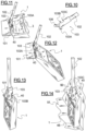
- the handle 102 of the broom comprises a hooking device 103 arranged and configured to cooperate with the hooking bar 40 of the bin 1.
- the hooking device 103 is arranged at one end of the handle 102.
- the hooking device 103 has the shape of a collar of substantially rectangular section and preferably comprising three hooks for cooperating with the hooking bar 40.
- On a first face of the hooking device there is arranged a hook 103B of curved shape projecting upwards and a hook 103C of curved shape projecting downwards.
- the hook 103B and the hook 103C together form a double hook in the shape of a “C” so that the space between them is sufficient to insert the hooking bar 40.
- On a second face of the hooking device 103, opposite the first face there is arranged a hook 103A of curved shape projecting upwards and making it possible to hook the hooking bar 40.
- the head 101 of the broom is placed outside the basin 3 and the hooking device 103 cooperates with the hooking bar 40, by means of the hook 103A.
- the user can lift the tank 1 using the hook 103A without bending down.
- the user can position the tank in a substantially vertical position.
- the hooking device 103 and the hooking bar 40 make it easier for the user to transport the tank.
- the cleaning liquid contained in the basin returns to the tank, and the used liquid contained in the collection chamber cannot escape due to the position of the outlet 9 of the collection chamber and the discharge orifice 12 which are then located at a height greater than the height of the level of used liquid in the collection chamber.
- the user can hang the broom and bin assembly by means of a hook, not shown, at a gripping end of the broom handle, opposite the end having the broom hanging device, so as for example to hang the assembly along a wall.
- the user can use the hook 103B to hang the bin and broom assembly. This arrangement allows the broom head 101 to be further inserted into the basin 3.
- the broom and bin assembly can also be placed on the ground via the bin.
- the bin is then in the upright position and rests on the ground 51 via a peripheral transverse side 45 of the bin.
- the side 45 is oblique so that the resting on the ground generates automatic resting against a neighboring wall.
- the broom then rests on the bin 1 via the hook 103C.
- the tank 1 during its use and in particular in the cleaning position.
- the term cleaning position means the position in which the bottom 1f of the tank is substantially parallel to the ground.
- the tank 2 is filled or almost filled with cleaning liquid L.
- the tank 2 is also filled with cleaning liquid.
- the tank 2 can be completely filled when placed in an inclined position as previously described during filling, then a quantity of cleaning liquid can flow from the tank 2 to the basin 3 in a sufficient manner until submerging the at least one opening 5 which interrupts the transfer of liquid L.
- the user positions the head 101 of the mop 100 in the basin 3 to moisten or soak the spongy body 104 before scrubbing the floor to be cleaned.
- the fringes 104 of the broom are preferably laid in the basin 3 to be moistened or soaked. If enough cleaning liquid has been taken, the at least one opening 5 provides an air intake for the reservoir 2 which again causes the transfer of the cleaning liquid L from the reservoir 2 to the basin 3 which lowers the level of the cleaning liquid in the reservoir 2, see figure 4c .
- the tub 1 is placed against a wall 50 to perform the wringing step. This allows the tub to be supported and stabilized.
- the tub includes non-slip pads arranged under it, so that it rests on the floor in the cleaning position by means of the non-slip pads.
- the user places the mop head in the wringing cone and turns the handle 102 of the mop in order to rub the fringes against the ribs of the wringing zone.
- the used liquid U flows into the collection chamber 8 which fills up a little more with each wringing, see in order the Figures 4c, 4d and 4e .
- the level of cleaning liquid L drops in tank 2 while it remains constant in basin 3 and the level of used liquid U increases in collection chamber 8.
Landscapes
- Cleaning Implements For Floors, Carpets, Furniture, Walls, And The Like (AREA)
- Cleaning By Liquid Or Steam (AREA)
Claims (15)
- Behälter (1) für die Haushaltsreinigung mit einer Reinigungsflüssigkeit (L), der Folgendes umfasst:- einen Tank (2) für eine Reinigungsflüssigkeit (L),- ein Becken (3), das so angeordnet ist, dass ein Schwammkörper (104) die Flüssigkeit (L) durch Absorption aufnehmen kann, wenn sich der Behälter in einer Reinigungsposition befindet,- eine Trennwand (4), die den Tank (2) für die Reinigungsflüssigkeit (L) und das Becken (3) trennt,- mindestens eine in der Trennwand (4) angeordnete Öffnung (5), die einen Durchgang für die Reinigungsflüssigkeit (L) zum Becken (3) bereitstellt,dadurch gekennzeichnet, dass die mindestens eine Öffnung (5) an den Boden des Behälters angrenzt und von einer oberen Wand des Tanks beabstandet ist, so dass ein Fassungsvermögen des Tanks, wenn die Öffnung (5) von der Reinigungsflüssigkeit (L) knapp überflutet ist, viel kleiner ist als das maximale Fassungsvermögen des Tanks, die Höhe der mindestens einen Öffnung (5) im Wesentlichen der Höhe des Reinigungsflüssigkeitsspiegels (L) im Becken (3) entspricht, während sich die Reinigungsflüssigkeit im Gleichgewicht zwischen dem Gefäß und dem Becken befindet, dass die mindestens eine Öffnung (5) eine ständige Verbindung zwischen dem Tank und dem Becken herstellt,und dass der Tank (2) für die Reinigungsflüssigkeit (L) luftdicht ist, wenn die mindestens eine Öffnung (5) von der Reinigungsflüssigkeit (L) überflutet ist.
- Behälter (1) nach Anspruch 1, dadurch gekennzeichnet, dass die Höhe der mindestens einen Öffnung (5) zwischen 1 und 15 mm, insbesondere zwischen 3 und 5 mm beträgt.
- Behälter (1) nach Anspruch 1 oder 2, dadurch gekennzeichnet, dass er eine Sammelkammer (8) für gebrauchte Flüssigkeit (U) umfasst.
- Behälter (1) nach Anspruch 3, dadurch gekennzeichnet, dass die Sammelkammer (8) für gebrauchte Flüssigkeit (U) und der Tank (2) für Reinigungsflüssigkeit (L) durch eine einzige Wand getrennt sind.
- Behälter (1) nach Anspruch 3 oder 4, dadurch gekennzeichnet, dass der Reinigungsflüssigkeitstank einen Bereich mit verringertem Querschnitt aufweist, der einen Durchgang zwischen dem Reinigungsflüssigkeitstank (2) und dem Becken (3) bildet, wobei der Durchgang in der Nähe einer Seite des Behälters angeordnet ist, die einem Auslass (9) der Sammelkammer (8) gegenübersteht.
- Behälter (1) nach einem der Ansprüche 1 bis 5, dadurch gekennzeichnet, dass er eine Entwässerungszone (10) mit mindestens einem Abstreifer (11) umfasst, der so angeordnet und gestaltet ist, dass der schwammartige Körper (104) darin gerieben werden kann.
- Behälter (1) nach Anspruch 6 in Abhängigkeit von Anspruch 3 oder 4, dadurch gekennzeichnet, dass die Entwässerungszone (10) mit der Sammelkammer (8) für gebrauchte Flüssigkeit (U) in Verbindung steht und sowohl über dieser als auch über dem Tank (2) für Reinigungsflüssigkeit (L) angeordnet ist.
- Behälter (1) nach einem der Ansprüche 1 bis 7, dadurch gekennzeichnet, dass die mindestens eine Öffnung (5) so angeordnet und gestaltet ist, dass sie durch geeignetes Kippen des Behälters einen Lufteinlass für den Reinigungsflüssigkeitstank (2) zum Füllen desselben bereitstellt.
- Behälter (1) nach einem der Ansprüche 1 bis 8, dadurch gekennzeichnet, dass er so angeordnet und ausgestaltet ist, dass er in einer aufrechten Position auf dem Boden stehen kann, in der sich das Becken (3) oberhalb des Reinigungsflüssigkeitstanks (2) befindet und die mindestens eine Öffnung (5) sich in einer höheren Position in Bezug auf den Reinigungsflüssigkeitstank (2) befindet.
- Behälter (1) nach einem der Ansprüche 1 bis 9, dadurch gekennzeichnet, dass sie eine Aufhängevorrichtung (40) in der Nähe des Beckens (3) umfasst, wobei die Aufhängevorrichtung so angeordnet und ausgestaltet ist, dass der Behälter aufgehängt werden kann.
- Behälter (1) nach einem der Ansprüche 1 bis 10, dadurch gekennzeichnet, dass der Tank (2) für Reinigungsflüssigkeit (L) abnehmbar ist.
- Behälter (1) nach einem der Ansprüche 3 bis 11, dadurch gekennzeichnet, dass die Sammelkammer (8) für verbrauchte Flüssigkeit (U) abnehmbar ist.
- Behälter (1) nach einem der Ansprüche 1 bis 8, dadurch gekennzeichnet, dass er einteilig ist.
- Anordnung mit einem für die Haushaltsreinigung bestimmten Behälter (1) nach einem oder mehreren der Ansprüche 1 bis 13, und einem zur Zusammenwirkung mit dem Behälter angeordneten und ausgestalteten Bodenwischer (100).
- Anordnung nach Anspruch 14, dadurch gekennzeichnet, dass der Bodenwischer (100) ein Mopp ist.
Applications Claiming Priority (2)
| Application Number | Priority Date | Filing Date | Title |
|---|---|---|---|
| FR1661096A FR3058627B1 (fr) | 2016-11-16 | 2016-11-16 | Bac destine au nettoyage menager, et ensemble comprenant un tel bac et un balai |
| PCT/EP2017/078816 WO2018091357A2 (fr) | 2016-11-16 | 2017-11-09 | Bac destine au nettoyage menager, et ensemble comprenant un tel bac et un balai |
Publications (3)
| Publication Number | Publication Date |
|---|---|
| EP3541259A2 EP3541259A2 (de) | 2019-09-25 |
| EP3541259B1 EP3541259B1 (de) | 2022-01-05 |
| EP3541259B2 true EP3541259B2 (de) | 2024-11-06 |
Family
ID=57750277
Family Applications (1)
| Application Number | Title | Priority Date | Filing Date |
|---|---|---|---|
| EP17803833.7A Active EP3541259B2 (de) | 2016-11-16 | 2017-11-09 | Haushaltsreinigungsbehälter und anordnung mit solch einem behälter und einem wischmopp |
Country Status (5)
| Country | Link |
|---|---|
| US (1) | US20190328203A1 (de) |
| EP (1) | EP3541259B2 (de) |
| ES (1) | ES2909049T5 (de) |
| FR (1) | FR3058627B1 (de) |
| WO (1) | WO2018091357A2 (de) |
Families Citing this family (6)
| Publication number | Priority date | Publication date | Assignee | Title |
|---|---|---|---|---|
| US11759085B2 (en) | 2018-05-29 | 2023-09-19 | Unger Marketing International, Llc | Floor cleaning system |
| EP3682786B1 (de) | 2019-01-18 | 2023-08-30 | Jemako Produktionsgesellschaft mbH | Vorrichtung zum reinigen von flächen |
| USD915703S1 (en) | 2019-05-28 | 2021-04-06 | Unger Marketng International, Llc | Flat headed mop |
| USD923896S1 (en) | 2019-05-28 | 2021-06-29 | Unger Marketing International, Llc | Floor cleaning system |
| US12048404B2 (en) | 2019-12-11 | 2024-07-30 | Unger Marketing International, Llc | Floor cleaning system, flat headed mop and mop pad |
| US11832775B2 (en) | 2021-01-07 | 2023-12-05 | Carl Freudenberg Kg | Rinse bucket for floor mop |
Citations (4)
| Publication number | Priority date | Publication date | Assignee | Title |
|---|---|---|---|---|
| US5743282A (en) † | 1995-08-07 | 1998-04-28 | Pellerin; Michel | Recuperation basin |
| US20040088781A1 (en) † | 2001-03-01 | 2004-05-13 | Udo Suffa | Device for dispensing portioned amounts |
| US7437795B1 (en) † | 2007-08-09 | 2008-10-21 | Kris Bez | Mop bucket assembly |
| EP1685027B1 (de) † | 2003-09-30 | 2012-08-15 | Levi Deaton | Frischspendereinigungsprodukt |
Family Cites Families (4)
| Publication number | Priority date | Publication date | Assignee | Title |
|---|---|---|---|---|
| US1807239A (en) * | 1929-03-05 | 1931-05-26 | Herman F Guentzler | Sponge cup |
| PT781524E (pt) | 1995-12-29 | 2002-04-29 | Vermop Salmon Gmbh | Dispositivo de doseamento destinado a liquido desinfectante e/ou liquido detergente |
| US20090194138A1 (en) * | 2008-02-01 | 2009-08-06 | Burns Phillip E | Sponge Sanitizer |
| WO2009097522A1 (en) * | 2008-02-01 | 2009-08-06 | Burns Phillip E | Sponge sanitizer |
-
2016
- 2016-11-16 FR FR1661096A patent/FR3058627B1/fr active Active
-
2017
- 2017-11-09 EP EP17803833.7A patent/EP3541259B2/de active Active
- 2017-11-09 US US16/349,630 patent/US20190328203A1/en not_active Abandoned
- 2017-11-09 WO PCT/EP2017/078816 patent/WO2018091357A2/fr not_active Ceased
- 2017-11-09 ES ES17803833T patent/ES2909049T5/es active Active
Patent Citations (4)
| Publication number | Priority date | Publication date | Assignee | Title |
|---|---|---|---|---|
| US5743282A (en) † | 1995-08-07 | 1998-04-28 | Pellerin; Michel | Recuperation basin |
| US20040088781A1 (en) † | 2001-03-01 | 2004-05-13 | Udo Suffa | Device for dispensing portioned amounts |
| EP1685027B1 (de) † | 2003-09-30 | 2012-08-15 | Levi Deaton | Frischspendereinigungsprodukt |
| US7437795B1 (en) † | 2007-08-09 | 2008-10-21 | Kris Bez | Mop bucket assembly |
Also Published As
| Publication number | Publication date |
|---|---|
| US20190328203A1 (en) | 2019-10-31 |
| EP3541259A2 (de) | 2019-09-25 |
| FR3058627B1 (fr) | 2020-11-13 |
| ES2909049T5 (en) | 2025-02-27 |
| ES2909049T3 (es) | 2022-05-05 |
| EP3541259B1 (de) | 2022-01-05 |
| WO2018091357A2 (fr) | 2018-05-24 |
| WO2018091357A3 (fr) | 2018-07-12 |
| FR3058627A1 (fr) | 2018-05-18 |
Similar Documents
| Publication | Publication Date | Title |
|---|---|---|
| EP3541259B2 (de) | Haushaltsreinigungsbehälter und anordnung mit solch einem behälter und einem wischmopp | |
| CA2718829C (fr) | Machine pour la preparation de boissons comprenant un systeme de nettoyage d'une buse vapeur | |
| FR2532346A1 (fr) | Support perfectionne pour produits nettoyants et/ou colorants, destine a etre accroche sous le rebord d'une cuvette de wc | |
| FR2550996A1 (fr) | Recipient d'encre et dispositif recuperateur d'encre, notamment pour imprimante | |
| FR2804066A1 (fr) | Bac a peinture a moyens de maintien de rouleau | |
| CH651874A5 (fr) | Dispensateur de liquide ne comportant pas de pieces mobiles. | |
| EP3467192B1 (de) | Elektrohaushaltsgerät, das eine basis mit einer verdampferkammer mit schwerkrafteinspeisung umfasst | |
| FR2967331A1 (fr) | Bac support pour mur vegetalise modulable | |
| CA2950998C (fr) | Boite avec sac interieur pour aliment liquide | |
| FR2474458A1 (fr) | Systeme de nettoyage de cuvettes de water-closets constitue par un receptacle dispose dans le reservoir d'eau associe a la cuvette | |
| EP1790214B1 (de) | Pflanztopf | |
| FR2701372A1 (fr) | Récipient à bec verseur, en particulier bouilloire électrique. | |
| FR2461449A2 (fr) | Perfectionnements aux installations de culture hydroponique | |
| EP1182303B1 (de) | Säuberungs- und Deodorierungsvorrichtung für eine Toilettenschüssel | |
| FR2618297A1 (fr) | Dispositif a reserve de liquide pour l'alimentation automatique notamment pot pour plante | |
| BE1000211A6 (fr) | Perfectionnements relatifs a un appareil de lavage. | |
| WO2000000077A1 (en) | An improved bucket | |
| FR2963958A1 (fr) | Reservoir auto-rechargeable avec clapet flottant | |
| EP2146012B1 (de) | Spülvorrichtung wobei eine gleichzeitige Einstellung von einem Schwimmer und einem Überlaufrohr möglich ist | |
| FR3158961A1 (fr) | Equipement de distribution de produit alimentaire liquide ou semi-liquide | |
| EP3091142B1 (de) | Gerät zur aufbringung eines flüssigen ausbesserungsprodukts | |
| FR2869261A1 (fr) | Dispositif permettant de faciliter le nettoyage des pinceaux, rouleaux ou autres outils utilises pour l'application de peintures, teintures ou divers produits | |
| FR2668593A1 (fr) | Appareil doseur de liquide a deux siphons. | |
| FR2793402A1 (fr) | Dispositif et procede de rincage d'un ustensile de service ou de cuisine | |
| WO2020157398A1 (fr) | Dispositif de stockage pour produits destinés à être immergés, son utilisation et ensemble de stockage correspondant |
Legal Events
| Date | Code | Title | Description |
|---|---|---|---|
| STAA | Information on the status of an ep patent application or granted ep patent |
Free format text: STATUS: UNKNOWN |
|
| STAA | Information on the status of an ep patent application or granted ep patent |
Free format text: STATUS: THE INTERNATIONAL PUBLICATION HAS BEEN MADE |
|
| PUAI | Public reference made under article 153(3) epc to a published international application that has entered the european phase |
Free format text: ORIGINAL CODE: 0009012 |
|
| STAA | Information on the status of an ep patent application or granted ep patent |
Free format text: STATUS: REQUEST FOR EXAMINATION WAS MADE |
|
| 17P | Request for examination filed |
Effective date: 20190524 |
|
| AK | Designated contracting states |
Kind code of ref document: A2 Designated state(s): AL AT BE BG CH CY CZ DE DK EE ES FI FR GB GR HR HU IE IS IT LI LT LU LV MC MK MT NL NO PL PT RO RS SE SI SK SM TR |
|
| AX | Request for extension of the european patent |
Extension state: BA ME |
|
| DAV | Request for validation of the european patent (deleted) | ||
| DAX | Request for extension of the european patent (deleted) | ||
| STAA | Information on the status of an ep patent application or granted ep patent |
Free format text: STATUS: EXAMINATION IS IN PROGRESS |
|
| 17Q | First examination report despatched |
Effective date: 20201012 |
|
| GRAP | Despatch of communication of intention to grant a patent |
Free format text: ORIGINAL CODE: EPIDOSNIGR1 |
|
| STAA | Information on the status of an ep patent application or granted ep patent |
Free format text: STATUS: GRANT OF PATENT IS INTENDED |
|
| INTG | Intention to grant announced |
Effective date: 20210709 |
|
| GRAS | Grant fee paid |
Free format text: ORIGINAL CODE: EPIDOSNIGR3 |
|
| GRAA | (expected) grant |
Free format text: ORIGINAL CODE: 0009210 |
|
| STAA | Information on the status of an ep patent application or granted ep patent |
Free format text: STATUS: THE PATENT HAS BEEN GRANTED |
|
| AK | Designated contracting states |
Kind code of ref document: B1 Designated state(s): AL AT BE BG CH CY CZ DE DK EE ES FI FR GB GR HR HU IE IS IT LI LT LU LV MC MK MT NL NO PL PT RO RS SE SI SK SM TR |
|
| REG | Reference to a national code |
Ref country code: GB Ref legal event code: FG4D Free format text: NOT ENGLISH |
|
| REG | Reference to a national code |
Ref country code: CH Ref legal event code: EP |
|
| REG | Reference to a national code |
Ref country code: AT Ref legal event code: REF Ref document number: 1459782 Country of ref document: AT Kind code of ref document: T Effective date: 20220115 |
|
| REG | Reference to a national code |
Ref country code: DE Ref legal event code: R096 Ref document number: 602017051953 Country of ref document: DE |
|
| REG | Reference to a national code |
Ref country code: IE Ref legal event code: FG4D Free format text: LANGUAGE OF EP DOCUMENT: FRENCH |
|
| REG | Reference to a national code |
Ref country code: LT Ref legal event code: MG9D |
|
| REG | Reference to a national code |
Ref country code: ES Ref legal event code: FG2A Ref document number: 2909049 Country of ref document: ES Kind code of ref document: T3 Effective date: 20220505 |
|
| REG | Reference to a national code |
Ref country code: NL Ref legal event code: MP Effective date: 20220105 |
|
| REG | Reference to a national code |
Ref country code: AT Ref legal event code: MK05 Ref document number: 1459782 Country of ref document: AT Kind code of ref document: T Effective date: 20220105 |
|
| PG25 | Lapsed in a contracting state [announced via postgrant information from national office to epo] |
Ref country code: NL Free format text: LAPSE BECAUSE OF FAILURE TO SUBMIT A TRANSLATION OF THE DESCRIPTION OR TO PAY THE FEE WITHIN THE PRESCRIBED TIME-LIMIT Effective date: 20220105 |
|
| PG25 | Lapsed in a contracting state [announced via postgrant information from national office to epo] |
Ref country code: SE Free format text: LAPSE BECAUSE OF FAILURE TO SUBMIT A TRANSLATION OF THE DESCRIPTION OR TO PAY THE FEE WITHIN THE PRESCRIBED TIME-LIMIT Effective date: 20220105 Ref country code: RS Free format text: LAPSE BECAUSE OF FAILURE TO SUBMIT A TRANSLATION OF THE DESCRIPTION OR TO PAY THE FEE WITHIN THE PRESCRIBED TIME-LIMIT Effective date: 20220105 Ref country code: PT Free format text: LAPSE BECAUSE OF FAILURE TO SUBMIT A TRANSLATION OF THE DESCRIPTION OR TO PAY THE FEE WITHIN THE PRESCRIBED TIME-LIMIT Effective date: 20220505 Ref country code: NO Free format text: LAPSE BECAUSE OF FAILURE TO SUBMIT A TRANSLATION OF THE DESCRIPTION OR TO PAY THE FEE WITHIN THE PRESCRIBED TIME-LIMIT Effective date: 20220405 Ref country code: LT Free format text: LAPSE BECAUSE OF FAILURE TO SUBMIT A TRANSLATION OF THE DESCRIPTION OR TO PAY THE FEE WITHIN THE PRESCRIBED TIME-LIMIT Effective date: 20220105 Ref country code: HR Free format text: LAPSE BECAUSE OF FAILURE TO SUBMIT A TRANSLATION OF THE DESCRIPTION OR TO PAY THE FEE WITHIN THE PRESCRIBED TIME-LIMIT Effective date: 20220105 Ref country code: BG Free format text: LAPSE BECAUSE OF FAILURE TO SUBMIT A TRANSLATION OF THE DESCRIPTION OR TO PAY THE FEE WITHIN THE PRESCRIBED TIME-LIMIT Effective date: 20220405 |
|
| PG25 | Lapsed in a contracting state [announced via postgrant information from national office to epo] |
Ref country code: PL Free format text: LAPSE BECAUSE OF FAILURE TO SUBMIT A TRANSLATION OF THE DESCRIPTION OR TO PAY THE FEE WITHIN THE PRESCRIBED TIME-LIMIT Effective date: 20220105 Ref country code: LV Free format text: LAPSE BECAUSE OF FAILURE TO SUBMIT A TRANSLATION OF THE DESCRIPTION OR TO PAY THE FEE WITHIN THE PRESCRIBED TIME-LIMIT Effective date: 20220105 Ref country code: GR Free format text: LAPSE BECAUSE OF FAILURE TO SUBMIT A TRANSLATION OF THE DESCRIPTION OR TO PAY THE FEE WITHIN THE PRESCRIBED TIME-LIMIT Effective date: 20220406 Ref country code: FI Free format text: LAPSE BECAUSE OF FAILURE TO SUBMIT A TRANSLATION OF THE DESCRIPTION OR TO PAY THE FEE WITHIN THE PRESCRIBED TIME-LIMIT Effective date: 20220105 Ref country code: AT Free format text: LAPSE BECAUSE OF FAILURE TO SUBMIT A TRANSLATION OF THE DESCRIPTION OR TO PAY THE FEE WITHIN THE PRESCRIBED TIME-LIMIT Effective date: 20220105 |
|
| PG25 | Lapsed in a contracting state [announced via postgrant information from national office to epo] |
Ref country code: IS Free format text: LAPSE BECAUSE OF FAILURE TO SUBMIT A TRANSLATION OF THE DESCRIPTION OR TO PAY THE FEE WITHIN THE PRESCRIBED TIME-LIMIT Effective date: 20220505 |
|
| REG | Reference to a national code |
Ref country code: DE Ref legal event code: R026 Ref document number: 602017051953 Country of ref document: DE |
|
| PLBI | Opposition filed |
Free format text: ORIGINAL CODE: 0009260 |
|
| PLAB | Opposition data, opponent's data or that of the opponent's representative modified |
Free format text: ORIGINAL CODE: 0009299OPPO |
|
| PLAX | Notice of opposition and request to file observation + time limit sent |
Free format text: ORIGINAL CODE: EPIDOSNOBS2 |
|
| PG25 | Lapsed in a contracting state [announced via postgrant information from national office to epo] |
Ref country code: SM Free format text: LAPSE BECAUSE OF FAILURE TO SUBMIT A TRANSLATION OF THE DESCRIPTION OR TO PAY THE FEE WITHIN THE PRESCRIBED TIME-LIMIT Effective date: 20220105 Ref country code: SK Free format text: LAPSE BECAUSE OF FAILURE TO SUBMIT A TRANSLATION OF THE DESCRIPTION OR TO PAY THE FEE WITHIN THE PRESCRIBED TIME-LIMIT Effective date: 20220105 Ref country code: RO Free format text: LAPSE BECAUSE OF FAILURE TO SUBMIT A TRANSLATION OF THE DESCRIPTION OR TO PAY THE FEE WITHIN THE PRESCRIBED TIME-LIMIT Effective date: 20220105 Ref country code: EE Free format text: LAPSE BECAUSE OF FAILURE TO SUBMIT A TRANSLATION OF THE DESCRIPTION OR TO PAY THE FEE WITHIN THE PRESCRIBED TIME-LIMIT Effective date: 20220105 Ref country code: DK Free format text: LAPSE BECAUSE OF FAILURE TO SUBMIT A TRANSLATION OF THE DESCRIPTION OR TO PAY THE FEE WITHIN THE PRESCRIBED TIME-LIMIT Effective date: 20220105 Ref country code: CZ Free format text: LAPSE BECAUSE OF FAILURE TO SUBMIT A TRANSLATION OF THE DESCRIPTION OR TO PAY THE FEE WITHIN THE PRESCRIBED TIME-LIMIT Effective date: 20220105 |
|
| 26 | Opposition filed |
Opponent name: REINERT, PETER Effective date: 20221004 |
|
| R26 | Opposition filed (corrected) |
Opponent name: REINERT, PETER Effective date: 20221004 |
|
| PG25 | Lapsed in a contracting state [announced via postgrant information from national office to epo] |
Ref country code: AL Free format text: LAPSE BECAUSE OF FAILURE TO SUBMIT A TRANSLATION OF THE DESCRIPTION OR TO PAY THE FEE WITHIN THE PRESCRIBED TIME-LIMIT Effective date: 20220105 |
|
| PLBB | Reply of patent proprietor to notice(s) of opposition received |
Free format text: ORIGINAL CODE: EPIDOSNOBS3 |
|
| PG25 | Lapsed in a contracting state [announced via postgrant information from national office to epo] |
Ref country code: SI Free format text: LAPSE BECAUSE OF FAILURE TO SUBMIT A TRANSLATION OF THE DESCRIPTION OR TO PAY THE FEE WITHIN THE PRESCRIBED TIME-LIMIT Effective date: 20220105 |
|
| PG25 | Lapsed in a contracting state [announced via postgrant information from national office to epo] |
Ref country code: MC Free format text: LAPSE BECAUSE OF FAILURE TO SUBMIT A TRANSLATION OF THE DESCRIPTION OR TO PAY THE FEE WITHIN THE PRESCRIBED TIME-LIMIT Effective date: 20220105 |
|
| REG | Reference to a national code |
Ref country code: CH Ref legal event code: PL |
|
| REG | Reference to a national code |
Ref country code: BE Ref legal event code: MM Effective date: 20221130 |
|
| PG25 | Lapsed in a contracting state [announced via postgrant information from national office to epo] |
Ref country code: LI Free format text: LAPSE BECAUSE OF NON-PAYMENT OF DUE FEES Effective date: 20221130 Ref country code: CH Free format text: LAPSE BECAUSE OF NON-PAYMENT OF DUE FEES Effective date: 20221130 |
|
| PG25 | Lapsed in a contracting state [announced via postgrant information from national office to epo] |
Ref country code: LU Free format text: LAPSE BECAUSE OF NON-PAYMENT OF DUE FEES Effective date: 20221109 |
|
| PG25 | Lapsed in a contracting state [announced via postgrant information from national office to epo] |
Ref country code: IE Free format text: LAPSE BECAUSE OF NON-PAYMENT OF DUE FEES Effective date: 20221109 |
|
| PG25 | Lapsed in a contracting state [announced via postgrant information from national office to epo] |
Ref country code: BE Free format text: LAPSE BECAUSE OF NON-PAYMENT OF DUE FEES Effective date: 20221130 |
|
| PLBP | Opposition withdrawn |
Free format text: ORIGINAL CODE: 0009264 |
|
| PG25 | Lapsed in a contracting state [announced via postgrant information from national office to epo] |
Ref country code: HU Free format text: LAPSE BECAUSE OF FAILURE TO SUBMIT A TRANSLATION OF THE DESCRIPTION OR TO PAY THE FEE WITHIN THE PRESCRIBED TIME-LIMIT; INVALID AB INITIO Effective date: 20171109 |
|
| PG25 | Lapsed in a contracting state [announced via postgrant information from national office to epo] |
Ref country code: CY Free format text: LAPSE BECAUSE OF FAILURE TO SUBMIT A TRANSLATION OF THE DESCRIPTION OR TO PAY THE FEE WITHIN THE PRESCRIBED TIME-LIMIT Effective date: 20220105 |
|
| PG25 | Lapsed in a contracting state [announced via postgrant information from national office to epo] |
Ref country code: MK Free format text: LAPSE BECAUSE OF FAILURE TO SUBMIT A TRANSLATION OF THE DESCRIPTION OR TO PAY THE FEE WITHIN THE PRESCRIBED TIME-LIMIT Effective date: 20220105 |
|
| PG25 | Lapsed in a contracting state [announced via postgrant information from national office to epo] |
Ref country code: MT Free format text: LAPSE BECAUSE OF FAILURE TO SUBMIT A TRANSLATION OF THE DESCRIPTION OR TO PAY THE FEE WITHIN THE PRESCRIBED TIME-LIMIT Effective date: 20220105 |
|
| PUAH | Patent maintained in amended form |
Free format text: ORIGINAL CODE: 0009272 |
|
| STAA | Information on the status of an ep patent application or granted ep patent |
Free format text: STATUS: PATENT MAINTAINED AS AMENDED |
|
| 27A | Patent maintained in amended form |
Effective date: 20241106 |
|
| AK | Designated contracting states |
Kind code of ref document: B2 Designated state(s): AL AT BE BG CH CY CZ DE DK EE ES FI FR GB GR HR HU IE IS IT LI LT LU LV MC MK MT NL NO PL PT RO RS SE SI SK SM TR |
|
| REG | Reference to a national code |
Ref country code: DE Ref legal event code: R102 Ref document number: 602017051953 Country of ref document: DE |
|
| PGFP | Annual fee paid to national office [announced via postgrant information from national office to epo] |
Ref country code: DE Payment date: 20241206 Year of fee payment: 8 |
|
| REG | Reference to a national code |
Ref country code: ES Ref legal event code: DC2A Ref document number: 2909049 Country of ref document: ES Kind code of ref document: T5 Effective date: 20250227 |
|
| PGFP | Annual fee paid to national office [announced via postgrant information from national office to epo] |
Ref country code: ES Payment date: 20250109 Year of fee payment: 8 |
|
| PG25 | Lapsed in a contracting state [announced via postgrant information from national office to epo] |
Ref country code: TR Free format text: LAPSE BECAUSE OF FAILURE TO SUBMIT A TRANSLATION OF THE DESCRIPTION OR TO PAY THE FEE WITHIN THE PRESCRIBED TIME-LIMIT Effective date: 20220105 |
|
| PGFP | Annual fee paid to national office [announced via postgrant information from national office to epo] |
Ref country code: GB Payment date: 20251126 Year of fee payment: 9 |
|
| PGFP | Annual fee paid to national office [announced via postgrant information from national office to epo] |
Ref country code: IT Payment date: 20251126 Year of fee payment: 9 |
|
| PGFP | Annual fee paid to national office [announced via postgrant information from national office to epo] |
Ref country code: FR Payment date: 20251127 Year of fee payment: 9 |