EP3540295B1 - Vehicle headlamp assembly - Google Patents
Vehicle headlamp assembly Download PDFInfo
- Publication number
- EP3540295B1 EP3540295B1 EP18161797.8A EP18161797A EP3540295B1 EP 3540295 B1 EP3540295 B1 EP 3540295B1 EP 18161797 A EP18161797 A EP 18161797A EP 3540295 B1 EP3540295 B1 EP 3540295B1
- Authority
- EP
- European Patent Office
- Prior art keywords
- light
- exit surface
- light emitter
- entry
- optical axis
- Prior art date
- Legal status (The legal status is an assumption and is not a legal conclusion. Google has not performed a legal analysis and makes no representation as to the accuracy of the status listed.)
- Active
Links
- 230000003287 optical effect Effects 0.000 claims description 26
- 238000005286 illumination Methods 0.000 description 4
- 230000009286 beneficial effect Effects 0.000 description 1
- 230000033228 biological regulation Effects 0.000 description 1
- 230000017525 heat dissipation Effects 0.000 description 1
- 238000009434 installation Methods 0.000 description 1
- 230000000007 visual effect Effects 0.000 description 1
Images


Classifications
-
- F—MECHANICAL ENGINEERING; LIGHTING; HEATING; WEAPONS; BLASTING
- F21—LIGHTING
- F21S—NON-PORTABLE LIGHTING DEVICES; SYSTEMS THEREOF; VEHICLE LIGHTING DEVICES SPECIALLY ADAPTED FOR VEHICLE EXTERIORS
- F21S41/00—Illuminating devices specially adapted for vehicle exteriors, e.g. headlamps
- F21S41/10—Illuminating devices specially adapted for vehicle exteriors, e.g. headlamps characterised by the light source
- F21S41/14—Illuminating devices specially adapted for vehicle exteriors, e.g. headlamps characterised by the light source characterised by the type of light source
- F21S41/141—Light emitting diodes [LED]
- F21S41/143—Light emitting diodes [LED] the main emission direction of the LED being parallel to the optical axis of the illuminating device
-
- F—MECHANICAL ENGINEERING; LIGHTING; HEATING; WEAPONS; BLASTING
- F21—LIGHTING
- F21S—NON-PORTABLE LIGHTING DEVICES; SYSTEMS THEREOF; VEHICLE LIGHTING DEVICES SPECIALLY ADAPTED FOR VEHICLE EXTERIORS
- F21S41/00—Illuminating devices specially adapted for vehicle exteriors, e.g. headlamps
- F21S41/20—Illuminating devices specially adapted for vehicle exteriors, e.g. headlamps characterised by refractors, transparent cover plates, light guides or filters
- F21S41/25—Projection lenses
- F21S41/27—Thick lenses
-
- F—MECHANICAL ENGINEERING; LIGHTING; HEATING; WEAPONS; BLASTING
- F21—LIGHTING
- F21S—NON-PORTABLE LIGHTING DEVICES; SYSTEMS THEREOF; VEHICLE LIGHTING DEVICES SPECIALLY ADAPTED FOR VEHICLE EXTERIORS
- F21S41/00—Illuminating devices specially adapted for vehicle exteriors, e.g. headlamps
- F21S41/20—Illuminating devices specially adapted for vehicle exteriors, e.g. headlamps characterised by refractors, transparent cover plates, light guides or filters
- F21S41/285—Refractors, transparent cover plates, light guides or filters not provided in groups F21S41/24-F21S41/28
Definitions
- the invention relates to a vehicle light assembly, as known from DE 10 2010 018 119 A1 or DE 20 2013 101 509 U1 .
- a vehicle light assembly disclosed in Taiwanese Patent No. I582335 , includes a light emitter module 1 and a heat dissipation member 2.
- the light emitter module 1 includes a lens 11 and a light emitter 12.
- the lens 1 has a light entry surface 111, a light exit surface 112 spaced apart from the light entry surface 111 along an optical axis (L), and two opposite flank surfaces 113 connecting the light entry surface 111 to the light exit surface 112 along the optical axis (L).
- the light emitter 12 emits light rays into the lens 11 through the light entry surface 111.
- Some light rays (A) (see arrow A in Fig. 2 ), which beam forwardly and exit from the light exit surface 112, are concentrated to a central area in front of the vehicle light assembly.
- Some light rays (B) (see arrow B in Fig. 2 ) are transmitted forwardly by multiple reflections between the flank surfaces 113 to exit from the light exit surface 112.
- the light rays (B), which are reflected from a left one of the flank surfaces 113 to the light exit surface 112, are emitted forward and rightward from the light exit surface 112 after exiting the light exit surface 112.
- the light rays (B), which are reflected from a right one of the flank surfaces 113 to the light exit surface 112, are emitted forward and leftward from the light exit surface 112 after exiting the light exit surface 112.
- the light rays (A) and (B) project a non-continuous light pattern on an illuminated plane which forms three discrete bright regions. Because dark regions appear between adjacent bright regions, the non-continuous light pattern is unable to provide satisfactory visual effects. Furthermore, because the flank surfaces 113 are essentially utilized for light reflection, the light pattern provided by the vehicle light assembly is significantly affected by the flank surfaces 113. Hence, it is impossible to vary greatly the profile and curvature of the flank surfaces 113 for improving design varieties.
- an object is to provide a vehicle light assembly that can alleviate at least one of the drawbacks of the prior art.
- a vehicle light assembly with the features of indenpendent claim 1 is provided.
- a vehicle light assembly includes a light emitter module 3.
- the light emitter module 3 includes a lens 4, a light emitter 5 disposed at a rear side of the lens 4, and a circuit board 51.
- the lens 4 includes a curved light exit surface 42 disposed at a front side of the lens 4, a light entry surface 41, left and right reflection surfaces 43, left and right bridge surfaces 44, and left and right flank surfaces 45.
- the light entry surface 41 is spaced apart from the curved light exit surface 42 along an optical axis (L), and is disposed adjacent to the light emitter 5.
- the light entry surface 41 has a first light entry portion 411, a base portion 410, and a second light entry portion 412.
- the optical axis (L) passes through the first light entry portion 411.
- the first light entry portion 411 is convexed rearwardly in a direction away from the curved light exit surface 42.
- the base portion 410 is flat and disposed around the optical axis (L) rearwardly of the first light entry portion 411.
- the second light entry portion 412 is connected between an annular inner periphery of the base portion 410 and the first light entry portion 411.
- the first and second light entry portions 411, 412 cooperatively bound a light entry hole 413.
- the light entry hole 413 has an opening 414 that faces rearward and that is formed in the base portion 410.
- the light entry hole 413 is immediately disposed at the front of the light emitter 5
- the first light entry portion (411) is immediately disposed at the front of the light entry hole 413.
- the first light entry portion 411 is convexed rearwardly into the light entry hole 413.
- the base portion 410 is close to the light emitter 5.
- the curved light exit surface 42 has an exit surface top side 42a, an exit surface bottom side 42b, an exit surface left side 42c, and an exit surface right side 42d (see Figs. 3 and 8 ).
- the curved light exit surface 42 protrudes arcuately and forwardly from the exit surface top and bottom sides 42a, 42b to a region disposed midway between the exit surface top and bottom sides 42a, 42b so that the exiting light rays can be directed forward and downward.
- the curved light exit surface 42 indents rearwardly and arcuately from the exit surface left and right sides 42c, 42d to a region disposed midway between the exit surface left and right sides 42c, 42d so that the exiting light rays slant slightly leftward and rightward to increase the range of illumination in a left-right direction.
- the left and right reflection surfaces 43 are respectively connected to left and right sides of the light entry surface 41 to reflect light rays of the light emitter 5 incident on the light entry surface 41 toward the curved light exit surface 42. Particularly, the left and right reflection surfaces 43 are respectively connected to left and right sides of the base portion 410. Each of left and right reflection surfaces 43 is a parabolic surface. The left or right reflection surface 43 should not be large. The length of the left or right reflection surface 43 in a front-rear direction is shorter than that of the left or right flank surface 45.
- the left and right bridge surfaces 44 respectively extend leftward and rightward from the left and right reflection surfaces 43 and connect rear ends of the left and right flank surfaces 45.
- the left and right flank surfaces 45 are respectively disposed at the left side of the left reflection surface 43 and the right side of the right reflection surface 43 and extend forwardly from the respective left and right bridge surfaces 44 to connect the curved light exit surface 42.
- a minimum distance (d1) of each of the left and right flank surfaces 45 from the optical axis (L) is greater than a maximum distance (d2) of each of the left and right reflection surfaces 43 from the optical axis (L).
- the light emitter 5 such as an LED, is mounted on the circuit board 51, and both of them are located rearward of the base portion 410 of the light entry surface 41.
- the light emitter 5 faces the first light entry portion 411 and the opening 414 of the light entry hole 413.
- the light emitter 5 has a center located at the optical axis (L), and the light emitter module 3 functions as a high beam light bulb.
- the light emitter module 3 functions as a low beam light bulb.
- the first light entry portion 411 which protrudes rearward, facilitates converging of the light rays after refraction.
- the left and right reflection surfaces 43 reflect the light rays to be closer to the optical axis (L) rather than toward the left and right flank surfaces 45. Afterwards, the light rays exit the curved light exit surface 42.
- the left reflection surface 43 reflects the light rays toward the curved light exit surface 42 at the left side of the optical axis (L).
- the right reflection surface 43 reflects the light rays to the curved light exit surface 42 at the right side of the optical axis (L).
- the curved light exit surface 42 can generate an illumination area sufficiently large to provide a light distribution pattern and brightness required by vehicle lighting regulations. Because the vehicle light assembly of the present invention can enable the exiting light rays to provide uniformly and continuously distributed lighting regions, occurrence of dark regions that interrupt or discontinue the light distribution pattern can be avoided.
- the light rays of the light emitter 5 are reflected by the left and right reflection surfaces 43, the light rays almost do not travel to the left and right flank surfaces 45.
- the left and right flank surfaces 45 are not main functional surfaces for reflecting the light rays and controlling the light distribution pattern. Accordingly, the left and right flank surfaces 45 may be provided with other design varieties, such as different extension directions, different curvatures, different slopes, different embossed patterns, etc., without affecting the desired light distribution pattern.
- the left and right reflection surfaces 43 are parabolic surfaces having respective focal points (F) disposed at a same location that has a distance from the entry surface 41 more longer than a distance of the light emitter 5 from the entry surface 41 and that is offset from the optical axis (L).
- the focal point (F) is at the rear side of the light emitter 5.
- the focal point (F) of the left and right reflection surfaces 43 falls to the location of the light emitter 5, or between the first light entry portion 411 of the light entry surface 41 and the light emitter 5 (i.e., at the front side of the light emitter 5), in order to achieve the desired optical effects, the light entry surface 41 will have to be located more forwardly and the curved light exit surface 42 will have to be adjusted and shifted forwardly. That is to say, the lens 4 will need an increased front-rear length (i.e., an increased distance between the base portion 410 and the curved light exit surface 42), which is not beneficial for miniaturization of the lens 4.
- the focal point (F) of the left and right reflection surfaces 43 is offset from the optical axis (L) and disposed at the distance from the entry surface 41 more longer than the distance of the light emitter 5 from the entry surface 41, the front-rear length of the lens 4 can be shortened for minimizing the lens 4.
- the optical axis (L) intersects the opening 414 at an intersection point (C).
- the first light entry portion 411 of the light entry surface 41 has a focal point located at the intersection point (C).
- the curved light exit surface 42 has a focal point located at the intersection point (C) or located in vicinity of the intersection point (C).
- a vehicle light assembly includes a plurality of the light emitter modules 3 juxtaposed to each other.
- One of the left and right flank surfaces 45 of each of the juxtaposed light emitter modules 3 faces one of left and right the flank surfaces 45 of the other one of the juxtaposed light emitter modules 3.
- the light emitter modules 3 are, but not limited to, juxtaposed to each other in a row. Every two adjacent light emitter modules 3 may be spaced apart from each other, or may adjoin each other. Further, at least one of the light emitter modules 3 functions as a high beam light bulb, and at least one of the light emitter modules 3 functions as a low beam light bulb. Therefore, the vehicle light assembly of the present invention can be controlled to provide the low beam function or high beam function. In other embodiments, all of the light emitter modules 3 may function as high or low beam light bulbs.
- the lenses 4 of the light emitter modules 3 can be juxtaposed to each other by adjoining the left and right flank surfaces 45 of every two adjacent ones of the lenses 4.
- a vehicle light assembly includes a plurality of the light emitter modules 3 juxtaposed to each other along a line and are integrally formed as one piece.
- the front-rear lengths of the light emitter modules 3 are different.
- a vehicle light assembly includes a plurality of the light emitter modules 3 are integrally interconnected and arranged to have an L-shaped configuration.
Description
- The invention relates to a vehicle light assembly, as known from
DE 10 2010 018 119 A1 orDE 20 2013 101 509 U1 . - As shown in
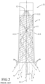
Figures 1 and2 , a vehicle light assembly, disclosed inTaiwanese Patent No. I582335 light emitter module 1 and aheat dissipation member 2. Thelight emitter module 1 includes alens 11 and alight emitter 12. Thelens 1 has alight entry surface 111, alight exit surface 112 spaced apart from thelight entry surface 111 along an optical axis (L), and twoopposite flank surfaces 113 connecting thelight entry surface 111 to thelight exit surface 112 along the optical axis (L). - The
light emitter 12 emits light rays into thelens 11 through thelight entry surface 111. Some light rays (A) (see arrow A inFig. 2 ), which beam forwardly and exit from thelight exit surface 112, are concentrated to a central area in front of the vehicle light assembly. Some light rays (B) (see arrow B inFig. 2 ) are transmitted forwardly by multiple reflections between theflank surfaces 113 to exit from thelight exit surface 112. The light rays (B), which are reflected from a left one of theflank surfaces 113 to thelight exit surface 112, are emitted forward and rightward from thelight exit surface 112 after exiting thelight exit surface 112. The light rays (B), which are reflected from a right one of theflank surfaces 113 to thelight exit surface 112, are emitted forward and leftward from thelight exit surface 112 after exiting thelight exit surface 112. - In practice, it is found that the light rays (A) and (B) project a non-continuous light pattern on an illuminated plane which forms three discrete bright regions. Because dark regions appear between adjacent bright regions, the non-continuous light pattern is unable to provide satisfactory visual effects. Furthermore, because the
flank surfaces 113 are essentially utilized for light reflection, the light pattern provided by the vehicle light assembly is significantly affected by theflank surfaces 113. Hence, it is impossible to vary greatly the profile and curvature of theflank surfaces 113 for improving design varieties. - Therefore, an object is to provide a vehicle light assembly that can alleviate at least one of the drawbacks of the prior art.
- According to the invention, a vehicle light assembly with the features of
indenpendent claim 1 is provided. - Other features and advantages of the invention will become apparent in the following detailed description of the embodiments with reference to the accompanying drawings, of which:
-
Figure 1 is a perspective view of an existing vehicle light assembly; -
Figure 2 is a top sectional view of the existing vehicle light assembly; -
Figure 3 is a rear perspective view of a vehicle light assembly according to a first embodiment of the present invention; -
Figure 4 is a side sectional view of the first embodiment functioning as a high beam light bulb; -
Figure 5 is a top sectional view of the first embodiment; -
Figure 6 is an enlarged fragmentary sectional view of the first embodiment; -
Figure 7 is a side sectional view of the first embodiment functioning as a low beam light bulb; -
Figure 8 is a front perspective view of a vehicle light assembly according to a second embodiment; -
Figure 9 is a front perspective view of a vehicle light assembly according to a third embodiment of the present invention; -
Figure 10 is a rear perspective view of the third embodiment; and -
Figure 11 is a front perspective view of a vehicle light assembly according to a fourth embodiment of the present invention. - Before the invention is described in greater detail, it should be noted that where considered appropriate, reference numerals or terminal portions of reference numerals have been repeated among the figures to indicate corresponding or analogous elements, which may optionally have similar characteristics.
- Referring to
Figures 3 to 6 , a vehicle light assembly according to a first embodiment of the present invention includes alight emitter module 3. Thelight emitter module 3 includes alens 4, alight emitter 5 disposed at a rear side of thelens 4, and acircuit board 51. - The
lens 4 includes a curvedlight exit surface 42 disposed at a front side of thelens 4, alight entry surface 41, left andright reflection surfaces 43, left andright bridge surfaces 44, and left andright flank surfaces 45. - The
light entry surface 41 is spaced apart from the curvedlight exit surface 42 along an optical axis (L), and is disposed adjacent to thelight emitter 5. Thelight entry surface 41 has a firstlight entry portion 411, abase portion 410, and a secondlight entry portion 412. The optical axis (L) passes through the firstlight entry portion 411. The firstlight entry portion 411 is convexed rearwardly in a direction away from the curvedlight exit surface 42. Thebase portion 410 is flat and disposed around the optical axis (L) rearwardly of the firstlight entry portion 411. The secondlight entry portion 412 is connected between an annular inner periphery of thebase portion 410 and the firstlight entry portion 411. The first and secondlight entry portions light entry hole 413. Thelight entry hole 413 has anopening 414 that faces rearward and that is formed in thebase portion 410. In other words, thelight entry hole 413 is immediately disposed at the front of thelight emitter 5, and the first light entry portion (411) is immediately disposed at the front of thelight entry hole 413. The firstlight entry portion 411 is convexed rearwardly into thelight entry hole 413. Thebase portion 410 is close to thelight emitter 5. - The curved
light exit surface 42 has an exitsurface top side 42a, an exitsurface bottom side 42b, an exit surfaceleft side 42c, and an exit surfaceright side 42d (seeFigs. 3 and8 ). The curvedlight exit surface 42 protrudes arcuately and forwardly from the exit surface top andbottom sides bottom sides light exit surface 42 indents rearwardly and arcuately from the exit surface left andright sides right sides light exit surface 42, it is possible to effectively control an illuminated area. - The left and
right reflection surfaces 43 are respectively connected to left and right sides of thelight entry surface 41 to reflect light rays of thelight emitter 5 incident on thelight entry surface 41 toward the curvedlight exit surface 42. Particularly, the left andright reflection surfaces 43 are respectively connected to left and right sides of thebase portion 410. Each of left andright reflection surfaces 43 is a parabolic surface. The left orright reflection surface 43 should not be large. The length of the left orright reflection surface 43 in a front-rear direction is shorter than that of the left orright flank surface 45. - The left and
right bridge surfaces 44 respectively extend leftward and rightward from the left andright reflection surfaces 43 and connect rear ends of the left andright flank surfaces 45. - The left and
right flank surfaces 45 are respectively disposed at the left side of theleft reflection surface 43 and the right side of theright reflection surface 43 and extend forwardly from the respective left andright bridge surfaces 44 to connect the curvedlight exit surface 42. A minimum distance (d1) of each of the left andright flank surfaces 45 from the optical axis (L) is greater than a maximum distance (d2) of each of the left andright reflection surfaces 43 from the optical axis (L). - The
light emitter 5, such as an LED, is mounted on thecircuit board 51, and both of them are located rearward of thebase portion 410 of thelight entry surface 41. Thelight emitter 5 faces the firstlight entry portion 411 and theopening 414 of thelight entry hole 413. In this embodiment, thelight emitter 5 has a center located at the optical axis (L), and thelight emitter module 3 functions as a high beam light bulb. Referring toFigure 7 , when an edge of thelight emitter 5 is located at the optical axis (L), thelight emitter module 3 functions as a low beam light bulb. By orienting thelight emitter 5 differently with respect to the optical axis (L), thelight emitter module 3 is capable of providing different illumination functions. - Referring back to the
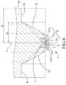
Figures 4 to 6 , when the light rays of thelight emitter 5 enter thelens 4 through the first and secondlight entry portions light entry surface 41, the firstlight entry portion 411, which protrudes rearward, facilitates converging of the light rays after refraction. The left andright reflection surfaces 43 reflect the light rays to be closer to the optical axis (L) rather than toward the left andright flank surfaces 45. Afterwards, the light rays exit the curvedlight exit surface 42. Theleft reflection surface 43 reflects the light rays toward the curvedlight exit surface 42 at the left side of the optical axis (L). Theright reflection surface 43 reflects the light rays to the curvedlight exit surface 42 at the right side of the optical axis (L). By virtue of the particular curvature and profile of the curvedlight exit surface 42, the curvedlight exit surface 42 can generate an illumination area sufficiently large to provide a light distribution pattern and brightness required by vehicle lighting regulations. Because the vehicle light assembly of the present invention can enable the exiting light rays to provide uniformly and continuously distributed lighting regions, occurrence of dark regions that interrupt or discontinue the light distribution pattern can be avoided. In addition, because the light rays of thelight emitter 5 are reflected by the left and right reflection surfaces 43, the light rays almost do not travel to the left and right flank surfaces 45. Therefore, the left and right flank surfaces 45 are not main functional surfaces for reflecting the light rays and controlling the light distribution pattern. Accordingly, the left and right flank surfaces 45 may be provided with other design varieties, such as different extension directions, different curvatures, different slopes, different embossed patterns, etc., without affecting the desired light distribution pattern. - Referring back to
Figure 5 and6 , the left and right reflection surfaces 43 are parabolic surfaces having respective focal points (F) disposed at a same location that has a distance from theentry surface 41 more longer than a distance of thelight emitter 5 from theentry surface 41 and that is offset from the optical axis (L). The focal point (F) is at the rear side of thelight emitter 5. Experiments showed that the aforesaid design can provide considerably high illumination efficiency and brightness. If the focal point (F) of the left and right reflection surfaces 43 falls to the location of thelight emitter 5, or between the firstlight entry portion 411 of thelight entry surface 41 and the light emitter 5 (i.e., at the front side of the light emitter 5), in order to achieve the desired optical effects, thelight entry surface 41 will have to be located more forwardly and the curvedlight exit surface 42 will have to be adjusted and shifted forwardly. That is to say, thelens 4 will need an increased front-rear length (i.e., an increased distance between thebase portion 410 and the curved light exit surface 42), which is not beneficial for miniaturization of thelens 4. According to the vehicle light assembly of the present disclosure, because the focal point (F) of the left and right reflection surfaces 43 is offset from the optical axis (L) and disposed at the distance from theentry surface 41 more longer than the distance of thelight emitter 5 from theentry surface 41, the front-rear length of thelens 4 can be shortened for minimizing thelens 4. Further, the optical axis (L) intersects theopening 414 at an intersection point (C). Optimally, the firstlight entry portion 411 of thelight entry surface 41 has a focal point located at the intersection point (C). The curvedlight exit surface 42 has a focal point located at the intersection point (C) or located in vicinity of the intersection point (C). - Referring to
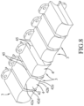
Figure 8 , a vehicle light assembly according to a second embodiment of the present invention includes a plurality of thelight emitter modules 3 juxtaposed to each other. One of the left and right flank surfaces 45 of each of the juxtaposedlight emitter modules 3 faces one of left and right the flank surfaces 45 of the other one of the juxtaposedlight emitter modules 3. In this embodiment, thelight emitter modules 3 are, but not limited to, juxtaposed to each other in a row. Every two adjacentlight emitter modules 3 may be spaced apart from each other, or may adjoin each other. Further, at least one of thelight emitter modules 3 functions as a high beam light bulb, and at least one of thelight emitter modules 3 functions as a low beam light bulb. Therefore, the vehicle light assembly of the present invention can be controlled to provide the low beam function or high beam function. In other embodiments, all of thelight emitter modules 3 may function as high or low beam light bulbs. - On the other hand, because the left and right flank surfaces 45 of each
lens 4 are not essential components for controlling the light distribution pattern, thelenses 4 of thelight emitter modules 3 can be juxtaposed to each other by adjoining the left and right flank surfaces 45 of every two adjacent ones of thelenses 4. By combining thelight emitter modules 3 in different ways, it is possible to not only provide various unique and aesthetically pleasing appearances, but also allow the vehicle light assembly to match suitably with different installation spaces and to function differently as high or low beam light bulbs. - Referring to
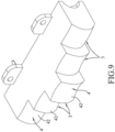
Figures 9 and10 , a vehicle light assembly according to a third embodiment of the present invention includes a plurality of thelight emitter modules 3 juxtaposed to each other along a line and are integrally formed as one piece. The front-rear lengths of thelight emitter modules 3 are different. - Referring to
Figure 11 , a vehicle light assembly according to a fourth embodiment of the present invention includes a plurality of thelight emitter modules 3 are integrally interconnected and arranged to have an L-shaped configuration.
Claims (10)
- A vehicle light assembly which comprises
at least one light emitter module (3) including a lens (4) and a light emitter (5) disposed at a rear side of said lens (4), said lens (4) includinga curved light exit surface (42) disposed at a front side of said lens (4),a light entry surface (41) spaced apart from said light exit surface (42) along an optical axis (L), and disposed adjacent to said light emitter (5), said light entry surface (41) having a first light entry portion (411) through which the optical axis (L) passes,left and right reflection surfaces (43) respectively connected to left and right sides of said light entry surface (41) to reflect light of said light emitter (5) passing through said light entry surface (41) to said curved light exit surface (42), each of said left and right reflection surfaces (43) being a parabolic surface and having a focal point (F) that is disposed at a distance from said entry surface (41) more longer than a distance of said light emitter (5) from said entry surface (41) and that is offset from the optical axis (L), andleft and right flank surfaces (45) respectively disposed at a left side of said left reflection surface (43) and a right side of said right reflection surface (43) and extending forwardly to connect said curved light exit surface (42) when viewed in the top sectional view of said lens,characterized by:each of said left and right flank surfaces (45) having a minimum distance (d1) from the optical axis (L), each of said left and right reflection surfaces (43) having a maximum distance (d2) from the optical axis (L), the minimum distance (d1) of each of said left and right flank surfaces (45) being greater than the maximum distance (d2) of each of said left and right reflection surfaces (43); andsaid first light entry portion (411) being convexed rearwardly in a direction away from said curved light exit surface (42) when viewed in a top sectional view of said lens;wherein said light entry surface (41) further has a base portion (410) and a second light entry portion (412), said base portion (410) disposed around the optical axis (L) rearwardly of said first light entry portion (411), said second light entry portion (412) being connected between an annular inner periphery of said base portion (410) and said first light entry portion (411), said first and second light entry portions (411, 412) cooperatively bounding a light entry hole (413); andwherein said focal point (F) of each of said left and right reflection surfaces (43) is at a rear side of said light emitter (5). - The vehicle light assembly as claimed in Claims 1, characterized in that said curved light exit surface (42) has an exit surface top side, an exit surface bottom side, an exit surface left side, and an exit surface right side, said curved light exit surface protruding arcuately and forwardly from said exit surface top and bottom sides to a region located midway between said exit surface top and bottom sides.
- The vehicle light assembly as claimed in Claim 2, characterized in that said curved light exit surface (42) indents rearwardly and arcuately from said exit surface left and right sides to a region located midway between said exit surface left and right sides.
- The vehicle light assembly as claimed in any one of Claims 1 to 3, characterized in that said light emitter (5) has a center located at the optical axis (L), said at least one light emitter module (3) functioning as a high beam light bulb.
- The vehicle light assembly as claimed in any one of Claims 1 to 3, characterized in that said light emitter (5) has an edge located at the optical axis (L), said at least one light emitter module (3) functioning as a low beam light bulb.
- The vehicle light assembly as claimed in Claim 1, characterized in that said at least one light emitter module includes a plurality of light emitter modules (3) juxtaposed to each other, one of said left and right flank surfaces (45) of each of said light emitter modules (3) facing one of left and right said flank surfaces (45) of the other one of said light emitter modules (3).
- The vehicle light assembly as claimed in Claim 1, characterized in that said at least one light emitter module includes a plurality of light emitter modules (3) juxtaposed to each other, at least one of said light emitter modules (3) functioning as a high beam light bulb, at least one of said light emitter modules (3) functioning as a low beam light bulb.
- The vehicle light assembly as claimed in Claim 1, characterized in that said at least one light emitter module (3) includes a plurality of light emitter modules (3) juxtaposed to each other, all of which function as high or low beam light bulbs.
- The vehicle light assembly as claimed in claim 1, characterized in that:
said light entry surface (41) further has a light entry hole (413) immediately disposed at a front of said light emitter (5), said first light entry portion (411) immediately disposed at a front of said light entry hole (413), the optical axis (L) passing through said light entry hole (413) and said first light entry portion (411), said first light entry portion (411) being convexed rearwardly into said light entry hole (413), - The vehicle light assembly as claimed in Claim 9,
characterized in that said light entry hole (413) has an opening (414) formed in said base portion (410), said left and right reflection surfaces (43) being connected to left and right sides of said base portion (410), said base portion (410) being close to said light emitter (5).
Priority Applications (2)
| Application Number | Priority Date | Filing Date | Title |
|---|---|---|---|
| ES18161797T ES2965827T3 (en) | 2018-03-14 | 2018-03-14 | Vehicle Headlight Assembly |
| EP18161797.8A EP3540295B1 (en) | 2018-03-14 | 2018-03-14 | Vehicle headlamp assembly |
Applications Claiming Priority (1)
| Application Number | Priority Date | Filing Date | Title |
|---|---|---|---|
| EP18161797.8A EP3540295B1 (en) | 2018-03-14 | 2018-03-14 | Vehicle headlamp assembly |
Publications (2)
| Publication Number | Publication Date |
|---|---|
| EP3540295A1 EP3540295A1 (en) | 2019-09-18 |
| EP3540295B1 true EP3540295B1 (en) | 2023-09-20 |
Family
ID=61683592
Family Applications (1)
| Application Number | Title | Priority Date | Filing Date |
|---|---|---|---|
| EP18161797.8A Active EP3540295B1 (en) | 2018-03-14 | 2018-03-14 | Vehicle headlamp assembly |
Country Status (2)
| Country | Link |
|---|---|
| EP (1) | EP3540295B1 (en) |
| ES (1) | ES2965827T3 (en) |
Families Citing this family (1)
| Publication number | Priority date | Publication date | Assignee | Title |
|---|---|---|---|---|
| DE102021130729B3 (en) | 2021-11-24 | 2023-01-26 | HELLA GmbH & Co. KGaA | Lighting device for vehicles |
Family Cites Families (8)
| Publication number | Priority date | Publication date | Assignee | Title |
|---|---|---|---|---|
| US4767172A (en) * | 1983-01-28 | 1988-08-30 | Xerox Corporation | Collector for an LED array |
| DE102010018119B4 (en) * | 2010-04-24 | 2023-06-22 | HELLA GmbH & Co. KGaA | Optical element for a lighting device of a vehicle |
| DE202013101509U1 (en) * | 2013-04-09 | 2013-04-23 | Fu An Industrial Co., Ltd. | Optical lens for strip lighting |
| DE102013207845A1 (en) * | 2013-04-29 | 2014-10-30 | Automotive Lighting Reutlingen Gmbh | Light module for a motor vehicle headlight |
| JP6241875B2 (en) * | 2013-12-06 | 2017-12-06 | スタンレー電気株式会社 | Vehicle headlamp |
| DE202014003078U1 (en) * | 2014-04-10 | 2014-04-17 | Osram Gmbh | Optical element and illumination device with optical element |
| TWI582335B (en) | 2015-02-26 | 2017-05-11 | T Y C Brother Industrial Co Ltd | Lights |
| AT518557B1 (en) * | 2016-04-29 | 2018-04-15 | Zkw Group Gmbh | Lighting unit for a motor vehicle headlight for generating a light beam with cut-off line |
-
2018
- 2018-03-14 ES ES18161797T patent/ES2965827T3/en active Active
- 2018-03-14 EP EP18161797.8A patent/EP3540295B1/en active Active
Also Published As
| Publication number | Publication date |
|---|---|
| EP3540295A1 (en) | 2019-09-18 |
| ES2965827T3 (en) | 2024-04-17 |
Similar Documents
| Publication | Publication Date | Title |
|---|---|---|
| US6805476B2 (en) | Led-type vehicular lamp having uniform brightness | |
| EP1598593B1 (en) | Headlamp unit for vehicle and headlamp unit assembly | |
| US11506358B2 (en) | Optical element, optical module, and vehicle | |
| EP1647764B1 (en) | Projector type vehicle headlamp unit | |
| EP2157363B1 (en) | Optical element for vehicle lamp | |
| US20080232127A1 (en) | Vehicle lamp | |
| EP2019257A1 (en) | Vehicle lighting assembly and light guiding lens for use n vehicle lighting assembly | |
| KR101975459B1 (en) | Lamp for vehicle | |
| JP6609135B2 (en) | Rear combination lamp for vehicles | |
| KR20080087656A (en) | Lamp unit for vehicular head lamp | |
| TWM560409U (en) | Vehicle lamp | |
| US11415286B2 (en) | Vehicle lamp | |
| US10253940B1 (en) | Vehicle light assembly | |
| KR101959805B1 (en) | Lamp for vehicle | |
| JP7227221B2 (en) | vehicle headlight | |
| EP3540295B1 (en) | Vehicle headlamp assembly | |
| JP6717646B2 (en) | Vehicle lighting | |
| TWI582335B (en) | Lights | |
| US10955105B2 (en) | Vehicle lamp | |
| KR101959804B1 (en) | Lamp for vehicle | |
| KR102558734B1 (en) | lamp for vehicle | |
| CN108916805B (en) | Car light lens | |
| US11885473B2 (en) | Vehicle lamp having a light source unit with chip laterally spaced from optical axis of optical unit and a reflector central axis tilted with respect to the optical axis | |
| EP3792548B1 (en) | Projection headlight | |
| WO2021141052A1 (en) | Vehicle lighting tool |
Legal Events
| Date | Code | Title | Description |
|---|---|---|---|
| PUAI | Public reference made under article 153(3) epc to a published international application that has entered the european phase |
Free format text: ORIGINAL CODE: 0009012 |
|
| STAA | Information on the status of an ep patent application or granted ep patent |
Free format text: STATUS: REQUEST FOR EXAMINATION WAS MADE |
|
| 17P | Request for examination filed |
Effective date: 20180314 |
|
| AK | Designated contracting states |
Kind code of ref document: A1 Designated state(s): AL AT BE BG CH CY CZ DE DK EE ES FI FR GB GR HR HU IE IS IT LI LT LU LV MC MK MT NL NO PL PT RO RS SE SI SK SM TR |
|
| AX | Request for extension of the european patent |
Extension state: BA ME |
|
| STAA | Information on the status of an ep patent application or granted ep patent |
Free format text: STATUS: EXAMINATION IS IN PROGRESS |
|
| 17Q | First examination report despatched |
Effective date: 20220210 |
|
| GRAP | Despatch of communication of intention to grant a patent |
Free format text: ORIGINAL CODE: EPIDOSNIGR1 |
|
| STAA | Information on the status of an ep patent application or granted ep patent |
Free format text: STATUS: GRANT OF PATENT IS INTENDED |
|
| INTG | Intention to grant announced |
Effective date: 20230413 |
|
| GRAS | Grant fee paid |
Free format text: ORIGINAL CODE: EPIDOSNIGR3 |
|
| GRAA | (expected) grant |
Free format text: ORIGINAL CODE: 0009210 |
|
| STAA | Information on the status of an ep patent application or granted ep patent |
Free format text: STATUS: THE PATENT HAS BEEN GRANTED |
|
| AK | Designated contracting states |
Kind code of ref document: B1 Designated state(s): AL AT BE BG CH CY CZ DE DK EE ES FI FR GB GR HR HU IE IS IT LI LT LU LV MC MK MT NL NO PL PT RO RS SE SI SK SM TR |
|
| REG | Reference to a national code |
Ref country code: GB Ref legal event code: FG4D |
|
| REG | Reference to a national code |
Ref country code: CH Ref legal event code: EP |
|
| REG | Reference to a national code |
Ref country code: DE Ref legal event code: R096 Ref document number: 602018057802 Country of ref document: DE |
|
| REG | Reference to a national code |
Ref country code: IE Ref legal event code: FG4D |
|
| GRAT | Correction requested after decision to grant or after decision to maintain patent in amended form |
Free format text: ORIGINAL CODE: EPIDOSNCDEC |
|
| REG | Reference to a national code |
Ref country code: DE Ref legal event code: R081 Ref document number: 602018057802 Country of ref document: DE Owner name: T.Y.C. BROTHER INDUSTRIAL CO., LTD., TW Free format text: FORMER OWNER: T.Y.C. BROTHER INDUSTRIAL CO., LTD., TAINAN, TW |
|
| RAP4 | Party data changed (patent owner data changed or rights of a patent transferred) |
Owner name: T.Y.C. BROTHER INDUSTRIAL CO., LTD. |
|
| REG | Reference to a national code |
Ref country code: LT Ref legal event code: MG9D |
|
| PG25 | Lapsed in a contracting state [announced via postgrant information from national office to epo] |
Ref country code: GR Free format text: LAPSE BECAUSE OF FAILURE TO SUBMIT A TRANSLATION OF THE DESCRIPTION OR TO PAY THE FEE WITHIN THE PRESCRIBED TIME-LIMIT Effective date: 20231221 |
|
| REG | Reference to a national code |
Ref country code: NL Ref legal event code: MP Effective date: 20230920 |
|
| PG25 | Lapsed in a contracting state [announced via postgrant information from national office to epo] |
Ref country code: SE Free format text: LAPSE BECAUSE OF FAILURE TO SUBMIT A TRANSLATION OF THE DESCRIPTION OR TO PAY THE FEE WITHIN THE PRESCRIBED TIME-LIMIT Effective date: 20230920 Ref country code: RS Free format text: LAPSE BECAUSE OF FAILURE TO SUBMIT A TRANSLATION OF THE DESCRIPTION OR TO PAY THE FEE WITHIN THE PRESCRIBED TIME-LIMIT Effective date: 20230920 Ref country code: NO Free format text: LAPSE BECAUSE OF FAILURE TO SUBMIT A TRANSLATION OF THE DESCRIPTION OR TO PAY THE FEE WITHIN THE PRESCRIBED TIME-LIMIT Effective date: 20231220 Ref country code: LV Free format text: LAPSE BECAUSE OF FAILURE TO SUBMIT A TRANSLATION OF THE DESCRIPTION OR TO PAY THE FEE WITHIN THE PRESCRIBED TIME-LIMIT Effective date: 20230920 Ref country code: LT Free format text: LAPSE BECAUSE OF FAILURE TO SUBMIT A TRANSLATION OF THE DESCRIPTION OR TO PAY THE FEE WITHIN THE PRESCRIBED TIME-LIMIT Effective date: 20230920 Ref country code: HR Free format text: LAPSE BECAUSE OF FAILURE TO SUBMIT A TRANSLATION OF THE DESCRIPTION OR TO PAY THE FEE WITHIN THE PRESCRIBED TIME-LIMIT Effective date: 20230920 Ref country code: GR Free format text: LAPSE BECAUSE OF FAILURE TO SUBMIT A TRANSLATION OF THE DESCRIPTION OR TO PAY THE FEE WITHIN THE PRESCRIBED TIME-LIMIT Effective date: 20231221 Ref country code: FI Free format text: LAPSE BECAUSE OF FAILURE TO SUBMIT A TRANSLATION OF THE DESCRIPTION OR TO PAY THE FEE WITHIN THE PRESCRIBED TIME-LIMIT Effective date: 20230920 |
|
| PG25 | Lapsed in a contracting state [announced via postgrant information from national office to epo] |
Ref country code: NL Free format text: LAPSE BECAUSE OF FAILURE TO SUBMIT A TRANSLATION OF THE DESCRIPTION OR TO PAY THE FEE WITHIN THE PRESCRIBED TIME-LIMIT Effective date: 20230920 |
|
| PG25 | Lapsed in a contracting state [announced via postgrant information from national office to epo] |
Ref country code: IS Free format text: LAPSE BECAUSE OF FAILURE TO SUBMIT A TRANSLATION OF THE DESCRIPTION OR TO PAY THE FEE WITHIN THE PRESCRIBED TIME-LIMIT Effective date: 20240120 |
|
| REG | Reference to a national code |
Ref country code: ES Ref legal event code: FG2A Ref document number: 2965827 Country of ref document: ES Kind code of ref document: T3 Effective date: 20240417 |
|
| PGFP | Annual fee paid to national office [announced via postgrant information from national office to epo] |
Ref country code: AT Payment date: 20240319 Year of fee payment: 7 |