EP3540273A1 - Dichtring - Google Patents
Dichtring Download PDFInfo
- Publication number
- EP3540273A1 EP3540273A1 EP19159896.0A EP19159896A EP3540273A1 EP 3540273 A1 EP3540273 A1 EP 3540273A1 EP 19159896 A EP19159896 A EP 19159896A EP 3540273 A1 EP3540273 A1 EP 3540273A1
- Authority
- EP
- European Patent Office
- Prior art keywords
- ring
- sealing
- lip
- support ring
- support
- Prior art date
- Legal status (The legal status is an assumption and is not a legal conclusion. Google has not performed a legal analysis and makes no representation as to the accuracy of the status listed.)
- Granted
Links
Images

Classifications
-
- F—MECHANICAL ENGINEERING; LIGHTING; HEATING; WEAPONS; BLASTING
- F16—ENGINEERING ELEMENTS AND UNITS; GENERAL MEASURES FOR PRODUCING AND MAINTAINING EFFECTIVE FUNCTIONING OF MACHINES OR INSTALLATIONS; THERMAL INSULATION IN GENERAL
- F16J—PISTONS; CYLINDERS; SEALINGS
- F16J15/00—Sealings
- F16J15/16—Sealings between relatively-moving surfaces
- F16J15/32—Sealings between relatively-moving surfaces with elastic sealings, e.g. O-rings
- F16J15/3204—Sealings between relatively-moving surfaces with elastic sealings, e.g. O-rings with at least one lip
- F16J15/3232—Sealings between relatively-moving surfaces with elastic sealings, e.g. O-rings with at least one lip having two or more lips
-
- F—MECHANICAL ENGINEERING; LIGHTING; HEATING; WEAPONS; BLASTING
- F16—ENGINEERING ELEMENTS AND UNITS; GENERAL MEASURES FOR PRODUCING AND MAINTAINING EFFECTIVE FUNCTIONING OF MACHINES OR INSTALLATIONS; THERMAL INSULATION IN GENERAL
- F16J—PISTONS; CYLINDERS; SEALINGS
- F16J15/00—Sealings
- F16J15/16—Sealings between relatively-moving surfaces
- F16J15/32—Sealings between relatively-moving surfaces with elastic sealings, e.g. O-rings
- F16J15/3204—Sealings between relatively-moving surfaces with elastic sealings, e.g. O-rings with at least one lip
-
- F—MECHANICAL ENGINEERING; LIGHTING; HEATING; WEAPONS; BLASTING
- F16—ENGINEERING ELEMENTS AND UNITS; GENERAL MEASURES FOR PRODUCING AND MAINTAINING EFFECTIVE FUNCTIONING OF MACHINES OR INSTALLATIONS; THERMAL INSULATION IN GENERAL
- F16J—PISTONS; CYLINDERS; SEALINGS
- F16J15/00—Sealings
- F16J15/16—Sealings between relatively-moving surfaces
- F16J15/32—Sealings between relatively-moving surfaces with elastic sealings, e.g. O-rings
- F16J15/3248—Sealings between relatively-moving surfaces with elastic sealings, e.g. O-rings provided with casings or supports
- F16J15/3252—Sealings between relatively-moving surfaces with elastic sealings, e.g. O-rings provided with casings or supports with rigid casings or supports
-
- F—MECHANICAL ENGINEERING; LIGHTING; HEATING; WEAPONS; BLASTING
- F16—ENGINEERING ELEMENTS AND UNITS; GENERAL MEASURES FOR PRODUCING AND MAINTAINING EFFECTIVE FUNCTIONING OF MACHINES OR INSTALLATIONS; THERMAL INSULATION IN GENERAL
- F16J—PISTONS; CYLINDERS; SEALINGS
- F16J15/00—Sealings
- F16J15/16—Sealings between relatively-moving surfaces
- F16J15/32—Sealings between relatively-moving surfaces with elastic sealings, e.g. O-rings
- F16J15/3268—Mounting of sealing rings
-
- F—MECHANICAL ENGINEERING; LIGHTING; HEATING; WEAPONS; BLASTING
- F16—ENGINEERING ELEMENTS AND UNITS; GENERAL MEASURES FOR PRODUCING AND MAINTAINING EFFECTIVE FUNCTIONING OF MACHINES OR INSTALLATIONS; THERMAL INSULATION IN GENERAL
- F16J—PISTONS; CYLINDERS; SEALINGS
- F16J15/00—Sealings
- F16J15/16—Sealings between relatively-moving surfaces
- F16J15/32—Sealings between relatively-moving surfaces with elastic sealings, e.g. O-rings
- F16J15/3268—Mounting of sealing rings
- F16J15/3276—Mounting of sealing rings with additional static sealing between the sealing, or its casing or support, and the surface on which it is mounted
-
- F—MECHANICAL ENGINEERING; LIGHTING; HEATING; WEAPONS; BLASTING
- F16—ENGINEERING ELEMENTS AND UNITS; GENERAL MEASURES FOR PRODUCING AND MAINTAINING EFFECTIVE FUNCTIONING OF MACHINES OR INSTALLATIONS; THERMAL INSULATION IN GENERAL
- F16F—SPRINGS; SHOCK-ABSORBERS; MEANS FOR DAMPING VIBRATION
- F16F2230/00—Purpose; Design features
- F16F2230/30—Sealing arrangements
-
- F—MECHANICAL ENGINEERING; LIGHTING; HEATING; WEAPONS; BLASTING
- F16—ENGINEERING ELEMENTS AND UNITS; GENERAL MEASURES FOR PRODUCING AND MAINTAINING EFFECTIVE FUNCTIONING OF MACHINES OR INSTALLATIONS; THERMAL INSULATION IN GENERAL
- F16F—SPRINGS; SHOCK-ABSORBERS; MEANS FOR DAMPING VIBRATION
- F16F9/00—Springs, vibration-dampers, shock-absorbers, or similarly-constructed movement-dampers using a fluid or the equivalent as damping medium
- F16F9/32—Details
- F16F9/36—Special sealings, including sealings or guides for piston-rods
- F16F9/369—Sealings for elements other than pistons or piston rods, e.g. valves
Definitions
- the invention relates to a sealing ring, comprising a lip ring with at least one sealing lip and a support ring, wherein the lip ring and the support ring are connected together.
- Such a sealing ring is well known, for example from the EP 1 288 538 A2 ,
- the lip ring is made of an elastomeric material and is non-destructively releasably connected to the support body, wherein the lip ring has a clamping bead, in which an annular helical spring is arranged.
- the clamping bead can be fixed under radial prestress on a counter surface of the support body.
- the support body may be formed as a housing of shock absorbers or hydraulic / pneumatic units and consists of a tough material.
- the sealing ring can seal a piston rod of a telescopic shock absorber.
- the sealing ring comprises a radially inner lip ring made of PTFE and a radially outer support ring, which consists of rubber. The lip and the support ring are integrally connected.
- the support ring of the known sealing ring may be made of rubber, because the lip ring made of PTFE has a good dimensional stability and thereby keeps the entire sealing ring in shape. Due to the different materials, in particular the fact that the relatively valuable PTFE material is very sparingly used only for the production of the lip ring, the entire sealing ring is inexpensive to produce.
- sealing rings described above are due to the production and during their intended use each formed substantially circular and have a good dimensional stability.
- This good dimensional stability is achieved in that one of the rings of the known sealing rings, here either the support body or the lip ring, consists of a tough, dimensionally stable material.
- the invention is based on the object, a sealing ring of the type mentioned in such a way that it is less dimensionally stable and sufficiently elastic, so that it can be used even if the sealed machine element deviates from a circular shape and / or or the installation space, in which the sealing ring is installed, has a shape deviating from a circular shape.
- the lip ring and the support ring each consist of a rubber-elastic material and that the lip ring has a smaller modulus of elasticity than the support ring.
- the lip ring nor the support ring made of a tough, substantially rigid and thus particularly dimensionally stable material. Rather, the lip ring and the support ring are both made of a rubber-elastic material, so that the entire sealing ring can be adapted particularly well to the particular circumstances of the application, even if the surface to be sealed of a machine element to be sealed is not substantially circular and / or the installation space has a shape deviating from a circular shape.
- the support ring has a larger compared to the lip ring modulus and thus is somewhat dimensionally stable compared to the lip ring and the relatively less dimensionally stable lip ring thereby supports.
- the sealing ring is as yielding as possible and only as dimensionally stable as necessary.
- sealing ring The preparation of such a sealing ring is simple and inexpensive. Due to manufacturing the sealing ring is circular. The production-related substantially circular lip ring is surrounded by the production reason substantially circular support ring outside circumference.
- the rubber-elastic sealing ring can be easily adapted during its assembly to the non-circular shape. Due to the rubber-elastic properties of the sealing ring, the sealing lip bears with the same elastic bias along the entire circumference of the machine element to be sealed, so that an undesirably high mechanical stress on the sealing lip is avoided and the sealing ring has consistently good performance characteristics during a long service life.
- the lip ring and the support ring each have an E-modulus which is 0.01 to 0.1 N / mm 2 .
- Such elasticity is common for rubber-elastic materials.
- a lip ring which would have an E-modulus ⁇ 0.01 N / mm 2 , would be disadvantageous, because thereby the sealing ring would have a total of insufficient dimensional stability.
- the ratio of modulus of elasticity of the support ring to modulus of elasticity of the lip ring is at least 1.25, more preferably 1.25 to 2.
- Such a ratio is relatively small, so that the lip ring and the support ring although a different, yet have a not too different elasticity.
- the support ring has one compared to the lip ring smaller elasticity in order to fulfill its support function for the lip ring. If the ratio described above were smaller, the supporting effect of the support ring for the lip ring would not be sufficient for most applications. In contrast, if the ratio were greater, the entire sealing ring would no longer be easily adapted to be sealed surfaces having a different form of the circular shape.
- the lip ring and the support ring can be non-destructively releasably connected to each other. By unbound and non-destructive detachable connection of lip ring and support ring, these two parts can be exchanged, if necessary, each separately.
- the lip ring has a high level of abrasive wear, for example by using a rod which is to be sealed in the axial direction in a heavily contaminated environment or the medium to be sealed contains many abrasive particles, it is advantageous to use that a worn during the service life of the sealing lip ring lip can be easily removed from the support body and replaced by a new lip ring.
- the mechanical connection between lip ring and support ring is based in such a case mainly on a radial bias, with which the lip ring is arranged in the support ring.
- the lip ring and the support ring can be non-positively and / or positively connected to each other.
- the lip ring and the support ring are cohesively connected to each other.
- the lip ring and the support ring thereby form a non-separable unit.
- unwanted Relative movements between the lip ring and the support ring are reliably excluded during assembly of the sealing ring and also during its intended use. The risk of assembly errors is minimized.
- the lip ring may have radially inner peripheral side and front side on both sides in each case at least one sealing lip.
- the sealing lips may be arched axially in the opposite direction to seal axially adjacent spaces against each other.
- One of the sealing lips is bulged, for example, in the direction of a sealed space of a sealing arrangement and seals medium to be sealed in a space to be sealed.
- the other, axially remote from the space to be sealed sealing lip prevents, for example, impurities from the environment penetrate in the direction of the space to be sealed.
- the two sealing lips may have a common root area from which they extend in axially opposite directions.
- the lip ring has radially outer peripheral side, axially between the sealing lips, at least one sealing bead.
- the sealing bead can form the aforementioned common root area.
- the sealing ring may be formed substantially symmetrically to an imaginary radial plane which extends axially through the center of the sealing bead, wherein one of the above-described sealing lips axially one end of the imaginary radial plane and the other axially on the other hand, the imaginary radial plane is arranged.
- a helical compression spring can be arranged with radially outwardly effective spring force.
- the helical compression spring is preferably self-contained and annular, so that the radial bias of the sealing bead along its entire circumference of matching size.
- the helical compression spring is completely enclosed by the material of the lip ring. Due to the complete sheathing of the helical compression spring material of the lip ring, the helical compression spring is reliably protected against corrosion. A time-consuming and costly treatment of the helical compression spring, for example, with a corrosion protection layer is therefore not required.
- the inner cavity of the helical compression spring which limit the turns of the helical compression spring outside, can be completely filled by the material of the lip ring.
- the production of the lip ring is considerably simplified by such an embodiment, because it requires no sealing of the inner cavity in the vulcanization of the lip ring. Due to the simple production of the entire sealing ring is simple and inexpensive to produce.
- the sealing bead has on the outer peripheral side a contact surface which sealingly contacts a counter surface of the support ring under radial elastic prestress.
- the contact surface and the counter surface are designed substantially congruent.
- the lip ring has a radially inner peripheral side axially between the sealing lips and radially inwardly of the sealing bead, a Vorschaltdichtung.
- Vorschaltdichtung the axially arranged in the direction of a sealed space sealing lip is better protected against exposure to contaminants from the environment.
- the axial gap between the end faces on both sides arranged sealing lips may, if necessary, be filled with a barrier grease to improve the sealing effect of the sealing ring.
- the barrier fat causes lubrication of the sealing lips, which are not directly acted upon by the medium to be sealed. Due to the lubricating effect abrasive wear of the sealing lips and / or the Vorschaltdichtung is significantly reduced and the sealing ring has consistently good performance for a long service life.
- At least one of the sealing lips are radially outer peripheral side surrounded by a ring helical spring, with radially inwardly effective spring force.
- the sealing lips reliably seal even when there is no or only a particularly small differential pressure between the two spaces to be sealed.
- a possible relaxation of the rubber-elastic material of the lip ring plays virtually no role, because the ring helical springs provide for a radial contact pressure of the sealing lips on the surface to be sealed of the machine element to be sealed.
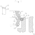
- the sealing ring according to the invention is shown therein as part of a sealing arrangement in a schematic representation.
- FIG. 2 different cross-sections of the machine element to be sealed are shown in a schematic representation. On the outer circumference, the cross sections are each enclosed by the sealing ring according to the invention.
- FIG. 1 the sealing ring according to the invention is shown, which is arranged in an installation space 12 of a seal arrangement.
- the installation space 12 is bounded radially on the inside by a machine element 13 to be sealed with a surface 14 to be sealed, and radially on the outside by a housing 15 which encloses the machine element 13 to be sealed at a radial distance on the outer peripheral side.
- the gap 16 formed by the radial distance forms the installation space 12.
- the machine element 13 to be sealed has a surface 14 to be sealed, which has a shape deviating from a circular shape.
- the sealed machine element 13 is, viewed in cross section, elliptical Das To be sealed machine element 13 may be, for example, the dip tube of a telescopic damper, which has an elliptical cross-section.
- the wall of the housing 15 delimiting the installation space 12 is designed correspondingly so that the wall of the housing 15 delimiting the installation space 12 has a shape which is adapted to the surface 14 to be sealed and is likewise elliptical.
- the radial width of the gap 16, viewed in the circumferential direction 17 of the machine element 13 to be sealed, is constant.
- the lip ring 1 and the support ring 3 are each made of a rubber-elastic material, wherein the support ring 3 has a lower elasticity than the lip ring 1 in order to support the lip ring 1 can.
- the ratio of the modulus of elasticity of the support ring 3 to the modulus of elasticity of the lip ring 1 is 1.25 to 2.
- the lip ring 1 has radially inner peripheral side and front side on both sides of the sealing lips 2, 4, wherein, viewed in the axial direction, between the sealing lips 2, 4, the Vorschaltdichtung 9 is arranged. Both sealing lips 2, 4 and the Vorschaltdichtung 9 enclose the sealed surface 14 of the sealed machine element 13 under radial prestressing sealing.
- the sealing lips 2, 4 are radially outer peripheral side in each case enclosed by the corresponding annular helical spring 10, 11, with radially inwardly effective spring force.
- the sealing ring is formed substantially symmetrically to the imaginary radial plane 18, which extends in the radial direction and axially centrally through the sealing bead 5.
- the helical compression spring 6 is arranged, which provides by its radially outwardly effective spring force for a radial bias, with which the lip ring 1 is arranged in the support ring 3.
- the helical compression spring 6 is completely enclosed on the outer peripheral side by the rubber-elastic material of the lip ring 1 and completely filled on the inner peripheral side.
- the support ring 3 forms a static seal to the housing 15th
- FIG. 2 different cross-sections of the sealed machine element 13 are shown in a schematic representation.
- the cross sections are each sealingly enclosed by the sealing ring according to the invention.
- the cross section may be substantially elliptical as described above.
- oval, teardrop-shaped, kidney-shaped or substantially 8-shaped cross sections can be sealed by the sealing ring according to the invention.
Landscapes
- Engineering & Computer Science (AREA)
- General Engineering & Computer Science (AREA)
- Mechanical Engineering (AREA)
- Sealing With Elastic Sealing Lips (AREA)
Abstract
Description
- Die Erfindung betrifft einen Dichtring, umfassend einen Lippenring mit zumindest einer Dichtlippe und einen Stützring, wobei der Lippenring und der Stützring miteinander verbunden sind.
- Ein solcher Dichtring ist allgemein bekannt, zum Beispiel aus der
EP 1 288 538 A2 . - Der Lippenring besteht aus einem elastomeren Werkstoff und ist zerstörungsfrei lösbar mit dem Stützkörper verbunden, wobei der Lippenring einen Klemmwulst aufweist, in dem eine ringförmig ausgebildete Schraubenfeder angeordnet ist. Der Klemmwulst ist unter radialer Vorspannung an einer Gegenfläche des Stützkörpers festlegbar.
- Der Stützkörper kann als Gehäuse von Stoßdämpfern oder Hydraulik- / Pneumatik-Aggregaten ausgebildet sein und besteht aus einem zähharten Werkstoff.
- Ein weiterer Dichtring ist aus der
DE 38 13 037 C1 bekannt. Der Dichtring kann eine Kolbenstange eines Teleskopstoßdämpfers abdichten. Der Dichtring umfasst einen radial innenliegenden Lippenring aus PTFE und einen radial außenliegenden Stützring, der aus Gummi besteht. Der Lippen- und der Stützring sind einstückig miteinander verbunden. - Der Stützring des vorbekannten Dichtrings kann aus Gummi bestehen, weil der Lippenring aus PTFE eine gute Formbeständigkeit aufweist und dadurch den gesamten Dichtring in Form hält. Durch die unterschiedlichen Materialien, insbesondere dadurch, dass das relativ wertvolle PTFE-Material sehr sparsam nur zur Herstellung des Lippenrings verwendet wird, ist der gesamte Dichtring kostengünstig herstellbar.
- Beide zuvor beschriebenen Dichtringe sind herstellungsbedingt und während ihrer bestimmungsgemäßen Verwendung jeweils im Wesentlichen kreisrund ausgebildet und weisen eine gute Formbeständigkeit auf. Diese gute Formbeständigkeit wird dadurch erreicht, dass einer der Ringe der vorbekannten Dichtringe, hier entweder der Stützkörper oder der Lippenring, aus einem zähharten, formstabilen Werkstoff besteht.
- Der Erfindung liegt die Aufgabe zu Grunde, einen Dichtring der eingangs genannten Art derart weiterzuentwickeln, dass dieser insgesamt weniger formbeständig und ausreichend elastisch ist, so dass er auch dann zur Anwendung gelangen kann, wenn das abzudichtende Maschinenelement eine von einer kreisrunden Form abweichende Form und/oder der Einbauraum, in dem der Dichtring eingebaut ist, eine von einer kreisrunden Form abweichende Form aufweist.
- Insbesondere sollen auch in Wesentlichen elliptische Oberflächen zuverlässig abgedichtet werden können.
- Diese Aufgabe wird erfindungsgemäß mit den Merkmalen von Anspruch 1 gelöst. Auf vorteilhafte Ausgestaltungen nehmen die Unteransprüche Bezug.
- Zur Lösung der Aufgabe ist es vorgesehen, dass der Lippenring und der Stützring jeweils aus einem gummielastischen Werkstoff bestehen und dass der Lippenring einen kleineren E-Modul als der Stützring aufweist.
- Hierbei ist von Vorteil, dass weder der Lippenring noch der Stützring aus einem zähharten, im Wesentlichen starren und damit besonders formbeständigen Werkstoff bestehen. Vielmehr bestehen der Lippenring und der Stützring beide aus einem gummielastischen Werkstoff, so dass sich der gesamte Dichtring besonders gut an die jeweiligen Gegebenheiten des Anwendungsfalles anpassen lässt, auch dann, wenn die abzudichtende Oberfläche eines abzudichtenden Maschinenelements nicht im Wesentlichen kreisrund ist und/oder der Einbauraum eine von einer kreisrunden Form abweichende Form aufweist.
- Trotz dieser gummielastischen Eigenschaften von Lippenring und Stützring ist von Vorteil, dass der Stützring einen im Vergleich zum Lippenring größeren E-Modul aufweist und dadurch im Vergleich zum Lippenring etwas formbeständiger ist und den relativ weniger formbeständig Lippenring dadurch stützt.
- Insgesamt ist der Dichtring dadurch so nachgiebig wie möglich und nur so formstabil wie nötig.
- Die Herstellung eines solchen Dichtrings ist einfach und kostengünstig möglich. Herstellungsbedingt ist der Dichtring kreisrund. Der herstellungsbedingt im Wesentlichen kreisrunde Lippenring ist vom herstellungsbedingt im Wesentlichen kreisrunden Stützring außenumfangsseitig umschlossen.
- Soll mit einem solchen Dichtring zum Beispiel eine nicht-kreisrunde Oberfläche, insbesondere eine elliptische Oberfläche, in einem entsprechend gestalteten Gehäuse abgedichtet werden, kann der gummielastische Dichtring während seiner Montage problemlos an die nicht-kreisrunde Form angepasst werden. Durch die gummielastischen Eigenschaften des Dichtrings liegt die Dichtlippe mit gleicher elastischer Vorspannung entlang des gesamten Umfangs des abzudichtenden Maschinenelements an, so dass eine unerwünscht hohe mechanische Beanspruchung der Dichtlippe vermieden wird und der Dichtring gleichbleibend gute Gebrauchseigenschaften während einer langen Gebrauchsdauer aufweist.
- Nach einer vorteilhaften Ausgestaltung kann es vorgesehen sein, dass der Lippenring und der Stützring jeweils einen E-Modul aufweisen, der 0,01 bis 0,1 N/mm2 beträgt. Eine derartige Elastizität ist für gummielastische Werkstoffe üblich. Dadurch kann der herstellungsbedingt im Wesentlichen kreisrunde Dichtring an die Gestalt abzudichtender Oberflächen auch dann gut angepasst werden, wenn diese nicht im Wesentlichen kreisrund sind.
- Ein Lippenring, der einen E-Modul < 0,01 N/mm2 hätte, wäre nachteilig, weil dadurch der Dichtring insgesamt eine nicht ausreichende Formbeständigkeit aufweisen würde.
- Wäre der E-Modul des Stützrings > 0,1 N/mm2, wäre die Formbeständigkeit des gesamten Dichtrings demgegenüber zu groß, und er würde sich nicht mehr in ausreichendem Maße an den jeweiligen Anwendungsfall anpassen lassen, wie zuvor beschrieben.
- Bevorzugt beträgt das Verhältnis aus E-Modul des Stützrings zu E-Modul des Lippenrings zumindest 1,25, weiter bevorzugt 1,25 bis 2. Ein solches Verhältnis ist vergleichsweise klein, so dass der Lippenring und der Stützring eine zwar von einander abweichende, dennoch eine nicht zu stark unterschiedliche Elastizität aufweisen. Der Stützring weist eine im Vergleich zum Lippenring kleinere Elastizität auf, um seine Stützfunktion für den Lippenring erfüllen zu können. Wäre das zuvor beschriebene Verhältnis kleiner, wäre die Stützwirkung des Stützrings für den Lippenring für die meisten Anwendungsfälle nicht ausreichend. Wäre das Verhältnis demgegenüber größer, würde sich der gesamte Dichtring nicht mehr problemlos an abzudichtende Oberflächen anpassen lassen, die eine von der kreisrunden Form abweichende Form aufweisen.
- Der Lippenring und der Stützring können zerstörungsfrei lösbar miteinander verbunden sein. Durch die ungebundene und zerstörungsfrei lösbare Verbindung von Lippenring und Stützring können diese beiden Teile bedarfsweise jeweils separat voneinander ausgetauscht werden. Für Anwendungsfälle, in denen der Lippenring einen hohen abrasiven Verschleiß aufweist, beispielsweise dadurch, dass eine abzudichtende, in axialer Richtung hin und her bewegliche Stange in einer stark verunreinigten Umgebung eingesetzt wird oder das abzudichtende Medium viele, abrasiv wirksame Partikel enthält, ist von Vorteil, dass ein im Laufe der Gebrauchsdauer des Dichtrings verschlissener Lippenring einfach vom Stützkörper entfernt und durch einen neuen Lippenring ersetzt werden kann. Die mechanische Verbindung zwischen Lippenring und Stützring beruht in einem solchen Fall hauptsächlich auf einer radialen Vorspannung, mit der der Lippenring im Stützring angeordnet ist.
- Der Lippenring und der Stützring können kraft- und/oder formschlüssig miteinander verbunden sein.
- Nach einer anderen Ausgestaltung kann es vorgesehen sein, dass der Lippenring und der Stützring stoffschlüssig miteinander verbunden sind. Der Lippenring und der Stützring bilden dadurch eine nicht-trennbare Einheit. Bei einer solchen Ausgestaltung ist von Vorteil, dass unerwünschte Relativbewegungen zwischen dem Lippenring und dem Stützring während der Montage des Dichtrings und auch während dessen bestimmungsgemäßer Verwendung zuverlässig ausgeschlossen sind. Die Gefahr von Montagefehlern ist minimiert.
- Der Lippenring kann radial innenumfangsseitig und stirnseitig beiderseits jeweils zumindest eine Dichtlippe aufweisen. Die Dichtlippen können axial in entgegengesetzter Richtung vorgewölbt sein, um axial zueinander benachbarte Räume gegeneinander abzudichten. Eine der Dichtlippen ist zum Beispiel in Richtung eines abzudichtenden Raums einer Dichtungsanordnung vorgewölbt und dichtet abzudichtendes Medium in einem abzudichtenden Raum ab. Die andere, axial vom abzudichtenden Raum abgewandte Dichtlippe verhindert, dass zum Beispiel Verunreinigungen aus der Umgebung in Richtung des abzudichtenden Raums vordringen. Die beiden Dichtlippen können einen gemeinsamen Wurzelbereich aufweisen, aus dem sie sich in axial entgegengesetzte Richtungen erstrecken.
- Zur statischen Abdichtung des Lippenrings im Stützring kann es vorgesehen sein, dass der Lippenring radial außenumfangsseitig, axial zwischen den Dichtlippen, zumindest einen Dichtwulst aufweist. Der Dichtwulst kann den zuvor genannten, gemeinsamen Wurzelbereich bilden.
- Der Dichtring kann zu einer gedachten Radialebene, die sich axial mittig durch den Dichtwulst erstreckt, im Wesentlichen symmetrisch ausgebildet sein, wobei von den zuvor beschriebenen Dichtlippen eine axial einerseits der gedachten Radialebene und die andere axial andererseits der gedachten Radialebene angeordnet ist.
- Im Dichtwulst kann eine Schraubendruckfeder mit radial nach außen wirksamer Federkraft angeordnet sein. Durch eine solche Schraubendruckfeder wird der Lippenring unter radialer Vorspannung im Stützring gehalten. Eine unerwünschte Relaxation des Dichtwulstes ist dadurch ausgeschlossen, und Lippenring und Stützring sind zuverlässig aneinander festgelegt.
- Die Schraubendruckfeder ist bevorzugt in sich geschlossen und ringförmig ausgebildet, so dass die radiale Vorspannung des Dichtwulstes entlang seines gesamten Umfangs von übereinstimmender Größe ist.
- Bevorzugt ist die Schraubendruckfeder vollständig vom Werkstoff des Lippenrings umschlossen. Durch die vollständige Ummantelung der Schraubendruckfeder vom Werkstoff des Lippenrings ist die Schraubendruckfeder zuverlässig vor Korrosion geschützt. Einer zeit- und kostenaufwändigen Behandlung der Schraubendruckfeder beispielsweise mit einer Korrosionsschutzschicht bedarf es deshalb nicht.
- Der innere Hohlraum der Schraubendruckfeder, den die Windungen der Schraubendruckfeder außenseitig begrenzen, kann vom Werkstoff des Lippenrings vollständig ausgefüllt sein. Die Herstellung des Lippenrings ist durch eine solche Ausgestaltung wesentlich vereinfacht, weil es keiner Abdichtung des inneren Hohlraums bei der Vulkanisation des Lippenrings bedarf. Durch die einfache Herstellung ist der gesamte Dichtring einfach und kostengünstig herstellbar.
- Der Dichtwulst weist außenumfangsseitig eine Kontaktfläche auf, die eine Gegenfläche des Stützrings unter radialer elastischer Vorspannung dichtend berührt.
- Insbesondere dann, wenn der Lippenring zerstörungsfrei lösbar mit dem Stützring verbunden ist, muss auf eine zuverlässige Abdichtung zwischen Kontaktfläche und Gegenfläche besonders geachtet werden.
- Dafür ist es von Vorteil, dass die Kontaktfläche und die Gegenfläche im Wesentlichen kongruent gestaltet sind.
- Sind der Lippenring und der Stützring demgegenüber stoffschlüssig miteinander verbunden, ist eine kongruente Gestalt von Kontaktfläche und Gegenfläche ebenfalls vorteilhaft. Dadurch entsteht eine insgesamt große Verbindungsfläche, die für eine zuverlässige Verbindung von Lippenring und Stützring von Vorteil ist.
- Zur Verbesserung der Dichtwirkung kann es vorgesehen sein, dass der Lippenring radial innenumfangsseitig axial zwischen den Dichtlippen und radial innenseitig des Dichtwulstes, eine Vorschaltdichtung aufweist. Durch die Vorschaltdichtung ist die axial in Richtung eines abzudichtenden Raums angeordnete Dichtlippe noch besser vor einer Beaufschlagung mit Verunreinigungen aus der Umgebung geschützt.
- Der axiale Zwischenraum zwischen den stirnseitig beiderseits angeordneten Dichtlippen kann bedarfsweise mit einem Sperrfett befüllt sein, um die Dichtwirkung des Dichtring zu verbessern. Außerdem bewirkt das Sperrfett eine Schmierung der Dichtlippen, die vom abzudichtenden Medium nicht unmittelbar beaufschlagt sind. Durch die Schmierwirkung wird abrasiver Verschleiß der Dichtlippen und/oder der Vorschaltdichtung deutlich reduziert und der Dichtring weist gleichbleibend gute Gebrauchseigenschaften während einer langen Gebrauchsdauer auf.
- Bevorzugt ist zumindest eine der Dichtlippen, weiter bevorzugt sind alle Dichtlippen radial außenumfangsseitig von einer Ringwendelfeder umschlossen, mit radial nach innen wirksamer Federkraft. Dadurch dichten die Dichtlippen auch dann zuverlässig ab, wenn kein oder nur ein besonders geringer Differenzdruck zwischen den beiden abzudichtenden Räumen besteht. Durch die Verwendung der Ringwendelfedern spielt eine mögliche Relaxation des gummielastischen Werkstoffs des Lippenrings praktisch keine Rolle, weil die Ringwendelfedern für eine radiale Anpressung der Dichtlippen an die abzudichtende Oberfläche des abzudichtenden Maschinenelements sorgen.
- Ein Ausführungsbeispiel des erfindungsgemäßen Dichtrings wird nachfolgend anhand von
Figur 1 näher erläutert. - Der erfindungsgemäße Dichtring ist darin als Bestandteil einer Dichtungsanordnung in schematischer Darstellung gezeigt.
- In
Figur 2 sind unterschiedliche Querschnitte des abzudichtenden Maschinenelements in schematischer Darstellung gezeigt. Aussenumfangsseitig sind die Querschnitte jeweils vom erfindungsgemäßen Dichtring umschlossen. - In
Figur 1 ist der erfindungsgemäße Dichtring gezeigt, der in einem Einbauraum 12 einer Dichtungsanordnung angeordnet ist. Der Einbauraum 12 wird radial innenseitig durch ein abzudichtendes Maschinenelement 13 mit einer abzudichtenden Oberfläche 14 begrenzt und radial außenseitig von einem Gehäuse 15, das das abzudichtende Maschinenelement 13 mit radialem Abstand außenumfangsseitig umschließt. Der durch den radialen Abstand gebildete Spalt 16 bildet den Einbauraum 12. - Im hier gezeigten Ausführungsbeispiel weist das abzudichtende Maschinenelement 13 eine abzudichtende Oberfläche 14 auf, die eine von einer kreisrunden Form abweichende Form aufweist. Das abzudichtende Maschinenelement 13 ist, im Querschnitt betrachtet, elliptisch Das abzudichtende Maschinenelement 13 kann zum Beispiel das Tauchrohr eines Teleskopdämpfers sein, das einen elliptischen Querschnitt aufweist. Entsprechend ausgebildet ist die den Einbauraum 12 begrenzende Wandung des Gehäuses 15, so dass die den Einbauraum 12 begrenzende Wandung des Gehäuses 15 eine an die abzudichtende Oberfläche 14 angepasste Gestalt aufweist und ebenfalls elliptisch ausgebildet ist.
- Die radiale Weite des Spalts 16 ist, in Umfangsrichtung 17 des abzudichtenden Maschinenelements 13 betrachtet, konstant.
- Der Lippenring 1 und der Stützring 3 bestehen jeweils aus einem gummielastischen Werkstoff, wobei der Stützring 3 eine geringere Elastizität als der Lippenring 1 aufweist, um den Lippenring 1 stützen zu können.
- Im hier gezeigten Ausführungsbeispiel beträgt das Verhältnis aus E-Modul des Stützrings 3 zur E-Modul des Lippenrings 1 1,25 bis 2.
- Der Lippenring 1 weist radial innenumfangsseitig und stirnseitig beiderseits die Dichtlippen 2, 4 auf, wobei, in axialer Richtung betrachtet, zwischen den Dichtlippen 2, 4 die Vorschaltdichtung 9 angeordnet ist. Beide Dichtlippen 2, 4 und die Vorschaltdichtung 9 umschließen die abzudichtende Oberfläche 14 des abzudichtenden Maschinenelements 13 unter radialer Vorspannung dichtend.
- Die Dichtlippen 2, 4 sind radial außenumfangsseitig jeweils von der entsprechenden Ringwendelfeder 10, 11 umschlossen, mit radial nach innen wirksamer Federkraft.
- Der Dichtring ist im Wesentlichen symmetrisch zur gedachten Radialebene 18 ausgebildet, die sich in radialer Richtung und axial mittig durch den Dichtwulst 5 erstreckt.
- Im Dichtwulst 5 ist die Schraubendruckfeder 6 angeordnet, die durch ihre radial nach außen wirksame Federkraft für eine radiale Vorspannung sorgt, mit der der Lippenring 1 im Stützring 3 angeordnet ist.
- Die Schraubendruckfeder 6 ist vom gummielastischen Werkstoff des Lippenrings 1 außenumfangsseitig vollständig umschlossen und innenumfangsseitig vollständig ausgefüllt.
- Der Stützring 3 bildet eine statische Abdichtung zum Gehäuse 15.
- In
Figur 2 sind unterschiedliche Querschnitte des abzudichtenden Maschinenelements 13 in schematischer Darstellung gezeigt. Aussenumfangsseitig sind die Querschnitte jeweils vom erfindungsgemäßen Dichtring dichtend umschlossen. Der Querschnitt kann, wie zuvor beschrieben, im Wesentlichen elliptisch sein. - Auch ovale, tropfenförmige, nierenförmige oder im Wesentlichen 8-förmige Querschnitte können durch den erfindungsgemäßen Dichtring abgedichtet werden.
Claims (15)
- Dichtring, umfassend einen Lippenring (1) mit zumindest einer Dichtlippe (2) und einen Stützring (3), wobei der Lippenring (1) und der Stützring (3) miteinander verbunden sind, dadurch gekennzeichnet, dass der Lippenring (1) und der Stützring (3) jeweils aus einem gummielastischen Werkstoff bestehen und dass der Lippenring (1) einen kleineren E-Modul als der Stützring (3) aufweist.
- Dichtring nach Anspruch 1, dadurch gekennzeichnet, dass der Lippenring (1) und der Stützring (3) jeweils einen E-Modul aufweisen, der 0,01 bis 0,1 N/mm2 beträgt.
- Dichtring nach einem der Ansprüche 1 oder 2, dadurch gekennzeichnet, dass das Verhältnis aus E-Modul des Stützrings (3) zu E-Modul des Lippenrings (1) zumindest 1,25 beträgt.
- Dichtring nach Anspruch 3, dadurch gekennzeichnet, dass das Verhältnis 1,25 bis 2 beträgt.
- Dichtring nach einem der Ansprüche 1 bis 4, dadurch gekennzeichnet, dass der Lippenring (1) und der Stützring (3) zerstörungsfrei lösbar miteinander verbunden sind.
- Dichtring nach Anspruch 5, dadurch gekennzeichnet, dass der Lippenring (1) und der Stützring (3) kraft- und/oder formschlüssig miteinander verbunden sind.
- Dichtring nach einem der Ansprüche 1 bis 4, dadurch gekennzeichnet, dass der Lippenring (1) und der Stützring (3) stoffschlüssig miteinander verbunden sind.
- Dichtring nach einem der Ansprüche 1 bis 7, dadurch gekennzeichnet, dass der Lippenring (1) radial innenumfangsseitig und stirnseitig beiderseits jeweils zumindest eine Dichtlippe (2, 4) aufweist.
- Dichtring nach einem der Ansprüche 1 bis 8, dadurch gekennzeichnet, dass der Lippenring (1) radial außenumfangsseitig, axial zwischen den Dichtlippen (2, 4), zumindest einen Dichtwulst (5) aufweist.
- Dichtring nach Anspruch 9, dadurch gekennzeichnet, dass im Dichtwulst (5) eine Schraubendruckfeder (6) mit radial nach außen wirksamer Federkraft angeordnet ist.
- Dichtring nach einem der Ansprüche 9 oder 10, dadurch gekennzeichnet, dass der Dichtwulst (5) außenumfangsseitig eine Kontaktfläche (7) aufweist, die eine Gegenfläche (8) des Stützrings (3) unter radialer elastischer Vorspannung anliegend berührt.
- Dichtring nach Anspruch 11, dadurch gekennzeichnet, dass die Kontaktfläche (7) und die Gegenfläche (8) kongruent gestaltet sind.
- Dichtring nach einem der Ansprüche 9 bis 12, dadurch gekennzeichnet, dass der Lippenring (1) radial innenumfangsseitig, axial zwischen den Dichtlippen (2, 4) und radial innenseitig des Dichtwulstes (5), eine Vorschaltdichtung (9) aufweist.
- Dichtring nach einem der Ansprüche 1 bis 11, dadurch gekennzeichnet, dass zumindest eine der Dichtlippen (2, 4) radial außenumfangsseitig von einer Ringwendelfeder (10, 11) mit radial nach innen wirksamer Federkraft umschlossen ist.
- Dichtring nach Anspruch 12, dadurch gekennzeichnet, dass alle Dichtlippen (2, 4) radial außenumfangsseitig jeweils von einer Ringwendelfeder (10, 11) mit radial nach innen wirksamer Federkraft umschlossen sind.
Applications Claiming Priority (1)
| Application Number | Priority Date | Filing Date | Title |
|---|---|---|---|
| DE102018105913.2A DE102018105913B4 (de) | 2018-03-14 | 2018-03-14 | Dichtring |
Publications (2)
| Publication Number | Publication Date |
|---|---|
| EP3540273A1 true EP3540273A1 (de) | 2019-09-18 |
| EP3540273B1 EP3540273B1 (de) | 2020-06-24 |
Family
ID=65635503
Family Applications (1)
| Application Number | Title | Priority Date | Filing Date |
|---|---|---|---|
| EP19159896.0A Active EP3540273B1 (de) | 2018-03-14 | 2019-02-28 | Dichtring |
Country Status (3)
| Country | Link |
|---|---|
| US (1) | US11236829B2 (de) |
| EP (1) | EP3540273B1 (de) |
| DE (1) | DE102018105913B4 (de) |
Cited By (1)
| Publication number | Priority date | Publication date | Assignee | Title |
|---|---|---|---|---|
| CN114542718A (zh) * | 2020-11-24 | 2022-05-27 | 舍弗勒技术股份两合公司 | 密封圈和密封单元 |
Families Citing this family (1)
| Publication number | Priority date | Publication date | Assignee | Title |
|---|---|---|---|---|
| EP4261439B1 (de) * | 2022-04-13 | 2025-08-27 | Robert Bosch GmbH | Dichtring für den radialen eingriff in eine aussenfläche einer drehwelle |
Citations (3)
| Publication number | Priority date | Publication date | Assignee | Title |
|---|---|---|---|---|
| FR2404782A1 (fr) * | 1977-09-28 | 1979-04-27 | Freudenberg Carl | Joint d'etancheite en anneau compose de deux parties |
| EP1288538A2 (de) * | 2001-08-27 | 2003-03-05 | Carl Freudenberg KG | Abstreifer |
| US20060006608A1 (en) * | 2004-06-28 | 2006-01-12 | Laplante Robert P | Sector shaft pressure seal |
Family Cites Families (18)
| Publication number | Priority date | Publication date | Assignee | Title |
|---|---|---|---|---|
| US4427206A (en) * | 1982-07-20 | 1984-01-24 | Keeper Co., Ltd. | Oil seal assembly with unbonded backup ring |
| DE3501334C1 (de) * | 1985-01-17 | 1986-04-10 | Fa. Carl Freudenberg, 6940 Weinheim | Dichtung |
| DE3603669A1 (de) * | 1986-02-06 | 1987-08-13 | Busak & Luyken Gmbh & Co | Doppelabstreifer-anordnung |
| AU7859987A (en) * | 1986-09-12 | 1988-04-07 | Fluhs Drehtechnik Gmbh | Valve seal |
| DE3813037C1 (de) | 1988-04-19 | 1989-09-14 | Fa. Carl Freudenberg, 6940 Weinheim, De | |
| US5263404A (en) * | 1992-01-09 | 1993-11-23 | A. W. Chesterton Company | Anti-rotation wiper ring |
| US5303935A (en) * | 1992-02-03 | 1994-04-19 | Saksun Holdings Limited | Fluid seal |
| DE4225142C2 (de) * | 1992-07-30 | 1996-07-18 | Daimler Benz Aerospace Ag | Vorrichtung zum Abdichten von metallischen zylindrischen Körpern |
| US6050572A (en) * | 1998-03-09 | 2000-04-18 | Bal Seal Engineering Company, Inc. | Rotary cartridge seals with retainer |
| US8702106B2 (en) * | 2006-07-20 | 2014-04-22 | Hydril Usa Manufacturing Llc | Pressure energized radial seal |
| US7828300B2 (en) * | 2006-09-21 | 2010-11-09 | Nok Corporation | Sealing device for reciprocating shaft |
| DE102012202571A1 (de) * | 2012-02-20 | 2013-08-22 | Trelleborg Sealing Solutions Germany Gmbh | Dichtungsanordnung und Verfahren zu dessen Herstellung |
| DE102012016559A1 (de) * | 2012-08-22 | 2014-02-27 | Carl Freudenberg Kg | Dichtungsanordnung und Protektorring |
| JP5977665B2 (ja) * | 2012-12-14 | 2016-08-24 | Kyb株式会社 | フロントフォーク |
| US9133937B1 (en) * | 2014-03-20 | 2015-09-15 | Engineered Seal Products, Inc. | Heavy-duty shaft seal |
| US20170184202A1 (en) * | 2015-12-28 | 2017-06-29 | Racingbros International Incorporation | Sealing member |
| JP7071273B2 (ja) * | 2017-04-12 | 2022-05-18 | Nok株式会社 | 密封装置 |
| JP6754385B2 (ja) * | 2018-03-13 | 2020-09-09 | Kyb株式会社 | シール部材、及び緩衝器 |
-
2018
- 2018-03-14 DE DE102018105913.2A patent/DE102018105913B4/de not_active Expired - Fee Related
-
2019
- 2019-02-28 EP EP19159896.0A patent/EP3540273B1/de active Active
- 2019-03-12 US US16/299,248 patent/US11236829B2/en active Active
Patent Citations (3)
| Publication number | Priority date | Publication date | Assignee | Title |
|---|---|---|---|---|
| FR2404782A1 (fr) * | 1977-09-28 | 1979-04-27 | Freudenberg Carl | Joint d'etancheite en anneau compose de deux parties |
| EP1288538A2 (de) * | 2001-08-27 | 2003-03-05 | Carl Freudenberg KG | Abstreifer |
| US20060006608A1 (en) * | 2004-06-28 | 2006-01-12 | Laplante Robert P | Sector shaft pressure seal |
Cited By (1)
| Publication number | Priority date | Publication date | Assignee | Title |
|---|---|---|---|---|
| CN114542718A (zh) * | 2020-11-24 | 2022-05-27 | 舍弗勒技术股份两合公司 | 密封圈和密封单元 |
Also Published As
| Publication number | Publication date |
|---|---|
| US11236829B2 (en) | 2022-02-01 |
| DE102018105913A1 (de) | 2019-09-19 |
| DE102018105913B4 (de) | 2021-01-14 |
| US20190285180A1 (en) | 2019-09-19 |
| EP3540273B1 (de) | 2020-06-24 |
Similar Documents
| Publication | Publication Date | Title |
|---|---|---|
| DE2709394C2 (de) | Wellendichtung | |
| DE69937495T2 (de) | Wellendichtung und verfahren zur herstellung | |
| DE19728605C2 (de) | Stangen- oder Kolbendichtung | |
| EP3540273B1 (de) | Dichtring | |
| DE102017006288B4 (de) | Radialwellendichtung und dessen Verwendung | |
| DE102005018442A1 (de) | Hydraulische Zylindereinheit | |
| EP3872373B1 (de) | Dichtring und dessen verwendung | |
| DE4210701C2 (de) | Dichtungsanordnung | |
| DE102016011448A1 (de) | Dichtring und dessen Verwendung | |
| DE3202381A1 (de) | "radial - wellendichtring" | |
| DE2609817A1 (de) | Kolben, insbesondere fuer einen pneumatikzylinder | |
| WO2002052180A2 (de) | Radialwellendichtung mit zwei dichtlippen | |
| EP3149366B1 (de) | Dicht- oder abstreifring | |
| EP1288538B1 (de) | Abstreifer | |
| DE102013018513A1 (de) | Abstreiferanordnung und/oder Dichtungsanordnung sowie Abstreifer und/oder Dichtring dafür | |
| DE19726433C2 (de) | Dichtungsanordnung | |
| DE702439C (de) | Einbaufertige Dichtung fuer Achsen und Wellen | |
| DE102018214312A1 (de) | Kolbenzylinder-Aggregat | |
| DE3543160A1 (de) | Gleitringdichtung | |
| EP1762757B1 (de) | Dichtungsanordnung | |
| DE2822615C3 (de) | Stangendichtung | |
| EP2647889A2 (de) | Dichtungsanordnung | |
| DE1948432A1 (de) | Gummielastischer,gewebeverstaerkter Dichtring fuer einen ungeteilten Kolben | |
| EP3511590B1 (de) | Dichtung und dichtungsanordnung, die die dichtung umfasst | |
| DE2019585A1 (de) | Abdichtung eines Gehaeuses gegenueber einer Welle oder einer Stange |
Legal Events
| Date | Code | Title | Description |
|---|---|---|---|
| PUAI | Public reference made under article 153(3) epc to a published international application that has entered the european phase |
Free format text: ORIGINAL CODE: 0009012 |
|
| STAA | Information on the status of an ep patent application or granted ep patent |
Free format text: STATUS: THE APPLICATION HAS BEEN PUBLISHED |
|
| AK | Designated contracting states |
Kind code of ref document: A1 Designated state(s): AL AT BE BG CH CY CZ DE DK EE ES FI FR GB GR HR HU IE IS IT LI LT LU LV MC MK MT NL NO PL PT RO RS SE SI SK SM TR |
|
| AX | Request for extension of the european patent |
Extension state: BA ME |
|
| STAA | Information on the status of an ep patent application or granted ep patent |
Free format text: STATUS: REQUEST FOR EXAMINATION WAS MADE |
|
| 17P | Request for examination filed |
Effective date: 20191022 |
|
| RBV | Designated contracting states (corrected) |
Designated state(s): AL AT BE BG CH CY CZ DE DK EE ES FI FR GB GR HR HU IE IS IT LI LT LU LV MC MK MT NL NO PL PT RO RS SE SI SK SM TR |
|
| GRAP | Despatch of communication of intention to grant a patent |
Free format text: ORIGINAL CODE: EPIDOSNIGR1 |
|
| STAA | Information on the status of an ep patent application or granted ep patent |
Free format text: STATUS: GRANT OF PATENT IS INTENDED |
|
| RIC1 | Information provided on ipc code assigned before grant |
Ipc: F16J 15/3252 20160101ALI20200226BHEP Ipc: F16J 15/3232 20160101AFI20200226BHEP |
|
| INTG | Intention to grant announced |
Effective date: 20200319 |
|
| GRAS | Grant fee paid |
Free format text: ORIGINAL CODE: EPIDOSNIGR3 |
|
| GRAA | (expected) grant |
Free format text: ORIGINAL CODE: 0009210 |
|
| STAA | Information on the status of an ep patent application or granted ep patent |
Free format text: STATUS: THE PATENT HAS BEEN GRANTED |
|
| AK | Designated contracting states |
Kind code of ref document: B1 Designated state(s): AL AT BE BG CH CY CZ DE DK EE ES FI FR GB GR HR HU IE IS IT LI LT LU LV MC MK MT NL NO PL PT RO RS SE SI SK SM TR |
|
| REG | Reference to a national code |
Ref country code: GB Ref legal event code: FG4D Free format text: NOT ENGLISH |
|
| REG | Reference to a national code |
Ref country code: CH Ref legal event code: EP |
|
| REG | Reference to a national code |
Ref country code: AT Ref legal event code: REF Ref document number: 1284219 Country of ref document: AT Kind code of ref document: T Effective date: 20200715 |
|
| REG | Reference to a national code |
Ref country code: DE Ref legal event code: R096 Ref document number: 502019000071 Country of ref document: DE |
|
| REG | Reference to a national code |
Ref country code: IE Ref legal event code: FG4D Free format text: LANGUAGE OF EP DOCUMENT: GERMAN |
|
| PG25 | Lapsed in a contracting state [announced via postgrant information from national office to epo] |
Ref country code: LT Free format text: LAPSE BECAUSE OF FAILURE TO SUBMIT A TRANSLATION OF THE DESCRIPTION OR TO PAY THE FEE WITHIN THE PRESCRIBED TIME-LIMIT Effective date: 20200624 Ref country code: FI Free format text: LAPSE BECAUSE OF FAILURE TO SUBMIT A TRANSLATION OF THE DESCRIPTION OR TO PAY THE FEE WITHIN THE PRESCRIBED TIME-LIMIT Effective date: 20200624 Ref country code: GR Free format text: LAPSE BECAUSE OF FAILURE TO SUBMIT A TRANSLATION OF THE DESCRIPTION OR TO PAY THE FEE WITHIN THE PRESCRIBED TIME-LIMIT Effective date: 20200925 Ref country code: NO Free format text: LAPSE BECAUSE OF FAILURE TO SUBMIT A TRANSLATION OF THE DESCRIPTION OR TO PAY THE FEE WITHIN THE PRESCRIBED TIME-LIMIT Effective date: 20200924 Ref country code: SE Free format text: LAPSE BECAUSE OF FAILURE TO SUBMIT A TRANSLATION OF THE DESCRIPTION OR TO PAY THE FEE WITHIN THE PRESCRIBED TIME-LIMIT Effective date: 20200624 |
|
| REG | Reference to a national code |
Ref country code: LT Ref legal event code: MG4D |
|
| PG25 | Lapsed in a contracting state [announced via postgrant information from national office to epo] |
Ref country code: HR Free format text: LAPSE BECAUSE OF FAILURE TO SUBMIT A TRANSLATION OF THE DESCRIPTION OR TO PAY THE FEE WITHIN THE PRESCRIBED TIME-LIMIT Effective date: 20200624 Ref country code: RS Free format text: LAPSE BECAUSE OF FAILURE TO SUBMIT A TRANSLATION OF THE DESCRIPTION OR TO PAY THE FEE WITHIN THE PRESCRIBED TIME-LIMIT Effective date: 20200624 Ref country code: BG Free format text: LAPSE BECAUSE OF FAILURE TO SUBMIT A TRANSLATION OF THE DESCRIPTION OR TO PAY THE FEE WITHIN THE PRESCRIBED TIME-LIMIT Effective date: 20200924 Ref country code: LV Free format text: LAPSE BECAUSE OF FAILURE TO SUBMIT A TRANSLATION OF THE DESCRIPTION OR TO PAY THE FEE WITHIN THE PRESCRIBED TIME-LIMIT Effective date: 20200624 |
|
| REG | Reference to a national code |
Ref country code: NL Ref legal event code: MP Effective date: 20200624 |
|
| PG25 | Lapsed in a contracting state [announced via postgrant information from national office to epo] |
Ref country code: AL Free format text: LAPSE BECAUSE OF FAILURE TO SUBMIT A TRANSLATION OF THE DESCRIPTION OR TO PAY THE FEE WITHIN THE PRESCRIBED TIME-LIMIT Effective date: 20200624 Ref country code: NL Free format text: LAPSE BECAUSE OF FAILURE TO SUBMIT A TRANSLATION OF THE DESCRIPTION OR TO PAY THE FEE WITHIN THE PRESCRIBED TIME-LIMIT Effective date: 20200624 |
|
| PG25 | Lapsed in a contracting state [announced via postgrant information from national office to epo] |
Ref country code: PT Free format text: LAPSE BECAUSE OF FAILURE TO SUBMIT A TRANSLATION OF THE DESCRIPTION OR TO PAY THE FEE WITHIN THE PRESCRIBED TIME-LIMIT Effective date: 20201026 Ref country code: IT Free format text: LAPSE BECAUSE OF FAILURE TO SUBMIT A TRANSLATION OF THE DESCRIPTION OR TO PAY THE FEE WITHIN THE PRESCRIBED TIME-LIMIT Effective date: 20200624 Ref country code: ES Free format text: LAPSE BECAUSE OF FAILURE TO SUBMIT A TRANSLATION OF THE DESCRIPTION OR TO PAY THE FEE WITHIN THE PRESCRIBED TIME-LIMIT Effective date: 20200624 Ref country code: RO Free format text: LAPSE BECAUSE OF FAILURE TO SUBMIT A TRANSLATION OF THE DESCRIPTION OR TO PAY THE FEE WITHIN THE PRESCRIBED TIME-LIMIT Effective date: 20200624 Ref country code: CZ Free format text: LAPSE BECAUSE OF FAILURE TO SUBMIT A TRANSLATION OF THE DESCRIPTION OR TO PAY THE FEE WITHIN THE PRESCRIBED TIME-LIMIT Effective date: 20200624 Ref country code: EE Free format text: LAPSE BECAUSE OF FAILURE TO SUBMIT A TRANSLATION OF THE DESCRIPTION OR TO PAY THE FEE WITHIN THE PRESCRIBED TIME-LIMIT Effective date: 20200624 Ref country code: SM Free format text: LAPSE BECAUSE OF FAILURE TO SUBMIT A TRANSLATION OF THE DESCRIPTION OR TO PAY THE FEE WITHIN THE PRESCRIBED TIME-LIMIT Effective date: 20200624 |
|
| PG25 | Lapsed in a contracting state [announced via postgrant information from national office to epo] |
Ref country code: SK Free format text: LAPSE BECAUSE OF FAILURE TO SUBMIT A TRANSLATION OF THE DESCRIPTION OR TO PAY THE FEE WITHIN THE PRESCRIBED TIME-LIMIT Effective date: 20200624 Ref country code: PL Free format text: LAPSE BECAUSE OF FAILURE TO SUBMIT A TRANSLATION OF THE DESCRIPTION OR TO PAY THE FEE WITHIN THE PRESCRIBED TIME-LIMIT Effective date: 20200624 Ref country code: IS Free format text: LAPSE BECAUSE OF FAILURE TO SUBMIT A TRANSLATION OF THE DESCRIPTION OR TO PAY THE FEE WITHIN THE PRESCRIBED TIME-LIMIT Effective date: 20201024 |
|
| REG | Reference to a national code |
Ref country code: DE Ref legal event code: R097 Ref document number: 502019000071 Country of ref document: DE |
|
| PG25 | Lapsed in a contracting state [announced via postgrant information from national office to epo] |
Ref country code: DK Free format text: LAPSE BECAUSE OF FAILURE TO SUBMIT A TRANSLATION OF THE DESCRIPTION OR TO PAY THE FEE WITHIN THE PRESCRIBED TIME-LIMIT Effective date: 20200624 |
|
| PLBE | No opposition filed within time limit |
Free format text: ORIGINAL CODE: 0009261 |
|
| STAA | Information on the status of an ep patent application or granted ep patent |
Free format text: STATUS: NO OPPOSITION FILED WITHIN TIME LIMIT |
|
| 26N | No opposition filed |
Effective date: 20210325 |
|
| PG25 | Lapsed in a contracting state [announced via postgrant information from national office to epo] |
Ref country code: SI Free format text: LAPSE BECAUSE OF FAILURE TO SUBMIT A TRANSLATION OF THE DESCRIPTION OR TO PAY THE FEE WITHIN THE PRESCRIBED TIME-LIMIT Effective date: 20200624 |
|
| PG25 | Lapsed in a contracting state [announced via postgrant information from national office to epo] |
Ref country code: MC Free format text: LAPSE BECAUSE OF FAILURE TO SUBMIT A TRANSLATION OF THE DESCRIPTION OR TO PAY THE FEE WITHIN THE PRESCRIBED TIME-LIMIT Effective date: 20200624 |
|
| REG | Reference to a national code |
Ref country code: BE Ref legal event code: MM Effective date: 20210228 |
|
| PG25 | Lapsed in a contracting state [announced via postgrant information from national office to epo] |
Ref country code: LU Free format text: LAPSE BECAUSE OF NON-PAYMENT OF DUE FEES Effective date: 20210228 |
|
| PG25 | Lapsed in a contracting state [announced via postgrant information from national office to epo] |
Ref country code: FR Free format text: LAPSE BECAUSE OF NON-PAYMENT OF DUE FEES Effective date: 20210228 Ref country code: IE Free format text: LAPSE BECAUSE OF NON-PAYMENT OF DUE FEES Effective date: 20210228 |
|
| PG25 | Lapsed in a contracting state [announced via postgrant information from national office to epo] |
Ref country code: BE Free format text: LAPSE BECAUSE OF NON-PAYMENT OF DUE FEES Effective date: 20210228 |
|
| REG | Reference to a national code |
Ref country code: CH Ref legal event code: PL |
|
| PG25 | Lapsed in a contracting state [announced via postgrant information from national office to epo] |
Ref country code: LI Free format text: LAPSE BECAUSE OF NON-PAYMENT OF DUE FEES Effective date: 20220228 Ref country code: CH Free format text: LAPSE BECAUSE OF NON-PAYMENT OF DUE FEES Effective date: 20220228 |
|
| PG25 | Lapsed in a contracting state [announced via postgrant information from national office to epo] |
Ref country code: CY Free format text: LAPSE BECAUSE OF FAILURE TO SUBMIT A TRANSLATION OF THE DESCRIPTION OR TO PAY THE FEE WITHIN THE PRESCRIBED TIME-LIMIT Effective date: 20200624 |
|
| PG25 | Lapsed in a contracting state [announced via postgrant information from national office to epo] |
Ref country code: HU Free format text: LAPSE BECAUSE OF FAILURE TO SUBMIT A TRANSLATION OF THE DESCRIPTION OR TO PAY THE FEE WITHIN THE PRESCRIBED TIME-LIMIT; INVALID AB INITIO Effective date: 20190228 |
|
| GBPC | Gb: european patent ceased through non-payment of renewal fee |
Effective date: 20230228 |
|
| PG25 | Lapsed in a contracting state [announced via postgrant information from national office to epo] |
Ref country code: GB Free format text: LAPSE BECAUSE OF NON-PAYMENT OF DUE FEES Effective date: 20230228 |
|
| PG25 | Lapsed in a contracting state [announced via postgrant information from national office to epo] |
Ref country code: GB Free format text: LAPSE BECAUSE OF NON-PAYMENT OF DUE FEES Effective date: 20230228 |
|
| PG25 | Lapsed in a contracting state [announced via postgrant information from national office to epo] |
Ref country code: MK Free format text: LAPSE BECAUSE OF FAILURE TO SUBMIT A TRANSLATION OF THE DESCRIPTION OR TO PAY THE FEE WITHIN THE PRESCRIBED TIME-LIMIT Effective date: 20200624 |
|
| PG25 | Lapsed in a contracting state [announced via postgrant information from national office to epo] |
Ref country code: TR Free format text: LAPSE BECAUSE OF FAILURE TO SUBMIT A TRANSLATION OF THE DESCRIPTION OR TO PAY THE FEE WITHIN THE PRESCRIBED TIME-LIMIT Effective date: 20200624 |
|
| PG25 | Lapsed in a contracting state [announced via postgrant information from national office to epo] |
Ref country code: MT Free format text: LAPSE BECAUSE OF FAILURE TO SUBMIT A TRANSLATION OF THE DESCRIPTION OR TO PAY THE FEE WITHIN THE PRESCRIBED TIME-LIMIT Effective date: 20200624 |
|
| REG | Reference to a national code |
Ref country code: AT Ref legal event code: MM01 Ref document number: 1284219 Country of ref document: AT Kind code of ref document: T Effective date: 20240228 |
|
| PG25 | Lapsed in a contracting state [announced via postgrant information from national office to epo] |
Ref country code: AT Free format text: LAPSE BECAUSE OF NON-PAYMENT OF DUE FEES Effective date: 20240228 |
|
| PGFP | Annual fee paid to national office [announced via postgrant information from national office to epo] |
Ref country code: DE Payment date: 20260220 Year of fee payment: 8 |
|
| PGFP | Annual fee paid to national office [announced via postgrant information from national office to epo] |
Ref country code: AT Payment date: 20260410 Year of fee payment: 5 |