EP3540112B1 - Reinigungsmittelbox und dazugehörige bekleidungsverarbeitungsvorrichtung - Google Patents
Reinigungsmittelbox und dazugehörige bekleidungsverarbeitungsvorrichtung Download PDFInfo
- Publication number
- EP3540112B1 EP3540112B1 EP17868982.4A EP17868982A EP3540112B1 EP 3540112 B1 EP3540112 B1 EP 3540112B1 EP 17868982 A EP17868982 A EP 17868982A EP 3540112 B1 EP3540112 B1 EP 3540112B1
- Authority
- EP
- European Patent Office
- Prior art keywords
- tub
- water
- detergent
- detergent box
- housing
- Prior art date
- Legal status (The legal status is an assumption and is not a legal conclusion. Google has not performed a legal analysis and makes no representation as to the accuracy of the status listed.)
- Active
Links
Images





Classifications
-
- D—TEXTILES; PAPER
- D06—TREATMENT OF TEXTILES OR THE LIKE; LAUNDERING; FLEXIBLE MATERIALS NOT OTHERWISE PROVIDED FOR
- D06F—LAUNDERING, DRYING, IRONING, PRESSING OR FOLDING TEXTILE ARTICLES
- D06F33/00—Control of operations performed in washing machines or washer-dryers
- D06F33/30—Control of washing machines characterised by the purpose or target of the control
- D06F33/32—Control of operational steps, e.g. optimisation or improvement of operational steps depending on the condition of the laundry
- D06F33/37—Control of operational steps, e.g. optimisation or improvement of operational steps depending on the condition of the laundry of metering of detergents or additives
-
- D—TEXTILES; PAPER
- D06—TREATMENT OF TEXTILES OR THE LIKE; LAUNDERING; FLEXIBLE MATERIALS NOT OTHERWISE PROVIDED FOR
- D06F—LAUNDERING, DRYING, IRONING, PRESSING OR FOLDING TEXTILE ARTICLES
- D06F37/00—Details specific to washing machines covered by groups D06F21/00 - D06F25/00
- D06F37/26—Casings; Tubs
- D06F37/267—Tubs specially adapted for mounting thereto components or devices not provided for in preceding subgroups
-
- D—TEXTILES; PAPER
- D06—TREATMENT OF TEXTILES OR THE LIKE; LAUNDERING; FLEXIBLE MATERIALS NOT OTHERWISE PROVIDED FOR
- D06F—LAUNDERING, DRYING, IRONING, PRESSING OR FOLDING TEXTILE ARTICLES
- D06F39/00—Details of washing machines not specific to a single type of machines covered by groups D06F9/00 - D06F27/00
- D06F39/02—Devices for adding soap or other washing agents
-
- D—TEXTILES; PAPER
- D06—TREATMENT OF TEXTILES OR THE LIKE; LAUNDERING; FLEXIBLE MATERIALS NOT OTHERWISE PROVIDED FOR
- D06F—LAUNDERING, DRYING, IRONING, PRESSING OR FOLDING TEXTILE ARTICLES
- D06F39/00—Details of washing machines not specific to a single type of machines covered by groups D06F9/00 - D06F27/00
- D06F39/02—Devices for adding soap or other washing agents
- D06F39/022—Devices for adding soap or other washing agents in a liquid state
-
- D—TEXTILES; PAPER
- D06—TREATMENT OF TEXTILES OR THE LIKE; LAUNDERING; FLEXIBLE MATERIALS NOT OTHERWISE PROVIDED FOR
- D06F—LAUNDERING, DRYING, IRONING, PRESSING OR FOLDING TEXTILE ARTICLES
- D06F39/00—Details of washing machines not specific to a single type of machines covered by groups D06F9/00 - D06F27/00
- D06F39/08—Liquid supply or discharge arrangements
- D06F39/088—Liquid supply arrangements
-
- D—TEXTILES; PAPER
- D06—TREATMENT OF TEXTILES OR THE LIKE; LAUNDERING; FLEXIBLE MATERIALS NOT OTHERWISE PROVIDED FOR
- D06F—LAUNDERING, DRYING, IRONING, PRESSING OR FOLDING TEXTILE ARTICLES
- D06F2103/00—Parameters monitored or detected for the control of domestic laundry washing machines, washer-dryers or laundry dryers
- D06F2103/18—Washing liquid level
-
- D—TEXTILES; PAPER
- D06—TREATMENT OF TEXTILES OR THE LIKE; LAUNDERING; FLEXIBLE MATERIALS NOT OTHERWISE PROVIDED FOR
- D06F—LAUNDERING, DRYING, IRONING, PRESSING OR FOLDING TEXTILE ARTICLES
- D06F2103/00—Parameters monitored or detected for the control of domestic laundry washing machines, washer-dryers or laundry dryers
- D06F2103/24—Spin speed; Drum movements
-
- D—TEXTILES; PAPER
- D06—TREATMENT OF TEXTILES OR THE LIKE; LAUNDERING; FLEXIBLE MATERIALS NOT OTHERWISE PROVIDED FOR
- D06F—LAUNDERING, DRYING, IRONING, PRESSING OR FOLDING TEXTILE ARTICLES
- D06F2105/00—Systems or parameters controlled or affected by the control systems of washing machines, washer-dryers or laundry dryers
- D06F2105/42—Detergent or additive supply
-
- D—TEXTILES; PAPER
- D06—TREATMENT OF TEXTILES OR THE LIKE; LAUNDERING; FLEXIBLE MATERIALS NOT OTHERWISE PROVIDED FOR
- D06F—LAUNDERING, DRYING, IRONING, PRESSING OR FOLDING TEXTILE ARTICLES
- D06F23/00—Washing machines with receptacles, e.g. perforated, having a rotary movement, e.g. oscillatory movement, the receptacle serving both for washing and for centrifugally separating water from the laundry
- D06F23/04—Washing machines with receptacles, e.g. perforated, having a rotary movement, e.g. oscillatory movement, the receptacle serving both for washing and for centrifugally separating water from the laundry and rotating or oscillating about a vertical axis
Definitions
- the present invention relates to a detergent box and a clothing processing apparatus including the same.
- the term "clothing processing apparatus” refers to an apparatus capable of performing washing and drying or either washing or drying of clothes and the like.
- the clothing processing apparatus may perform only the washing or drying function, or both the washing function and the drying function.
- washing machines provided with a steam supply device to perform a refresh function, such as removing wrinkles, odors, static electricity, and the like from clothes have been spreading.
- Conventional clothing processing apparatuses are divided into a front loading type and a top loading type according to a clothing retrieval direction. Also, clothing processing apparatuses are divided into a vertical type apparatus in which a pulsator or a washing tub is rotated, and a horizontal type in which a drum is rotated, by the manner of washing.
- a typical example of the horizontal type is a drum washing machine or a drum dryer.
- the size of such clothing processing apparatuses is gradually increasing in recent years to meet user demand. That is, the size of the washing machines for domestic use is gradually increasing.
- each household is equipped with one high-capacity clothing processing apparatus. Accordingly, when the laundry is to be washed by classifying the clothes according to the types of the clothes, the clothing processing apparatus is used many times. For example, when where laundry such as adult clothes and laundry such as underwear or baby clothes need to be separately washed, the clothing processing apparatus will be used for washing of the latter laundry after washing of the former laundry is completed.
- the washing phase presumes a large amount of laundry, the washing time is relatively long.
- the large-size clothing processing apparatus since the large-size clothing processing apparatus is provided with the washing phase considering typical clothes, it may not be suitable for washing of delicate fabrics such as underwear or baby clothes.
- the large-size clothing processing apparatus is not suitable for a case where a small amount of laundry needs to be frequently washed. Consumers collect laundry for a few days or a longer period to wash the laundry at a time.
- the conventional drawer-type clothing processing apparatus is provided with a drawer to be drawn in and out of a cabinet having an opening at the front thereof.
- the drawer-type clothing processing apparatus may be used alone or in combination with another clothing processing apparatus arranged at the top or bottom thereof to wash a small amount of laundry and enhance space utilization.
- the drawer-type clothing processing apparatus generally includes a tub configured to accommodate wash water in a drawer, and a drum rotatably arranged in the tub.
- a water supply unit configured to supply water to the tub and a drainage unit configured to drain water from the tub are generally provided at the rear of the drawer.
- the term “rear” refers to a side to which the drawer is inserted into the cabinet.
- the drawer may be provided with a detergent box.
- the detergent box of the conventional drawer-type clothing processing apparatus should be connected to a detergent watering pipe for supplying water, and also a detergent discharge pipe for discharging the detergent from the detergent box to the tub is separately provided.
- the user can reach the detergent box and introduce a detergent and a fabric softener into the detergent box only when the drawer is drawn out until a portion provided with the detergent box is exposed, which causes a great inconvenience to the user.
- the detergent watering pipe and the detergent discharge pipe connected to the detergent box needs to be elongated. Thereby, the space where the detergent watering pipe and the detergent discharge pipe can be installed may be narrowed, or the introduction port of the drum and the tub may be partially blocked due to the detergent watering pipe and the detergent discharge pipe.
- a separate valve for controlling the flow rates in the detergent watering pipe and the detergent discharge pipe, or a separate control means for opening and closing the valve needs to be provided, which causes inconvenience.
- EP 1 715 097 A1 relates to a washing machine having a rinse agent dispenser (30) and control method thereof.
- the rinse agent dispenser (30) is directly connected with a water tub (11) to automatically dispense a rinse agent into the water tub (11) via an adjustment of a level of wash water contained in the water tub (11) without requiring a separate water supply device.
- the washing machine includes the water tub (11), the rinse agent dispenser (30) connected with the water tub (11) to dispense the rinse agent into the water tub (11) via an adjustment of the level of the wash water contained in the water tub (11), water supply means to supply the wash water into the water tub (11), drainage means to drain the wash water from the water tub (11), and a controller to control the supply and drainage of the wash water by the water supply means and drainage means, thereby adjusting the level of the wash water in the water tub (11).
- An object of the present invention devised to solve the problem lies on a laundry treating apparatus having a detergent box which is capable of incorporating a water supply pipe for supplying water to the detergent box and a drain pipe into one pipe.
- Another object of the present invention is to provide a laundry treating apparatus having a detergent box which is capable of supplying water from a tub to the detergent box.
- Another object of the present invention is to provide a clothing processing device which uses rotation of a drum in supplying water to a detergent box and discharging a detergent.
- Another object of the present invention is to provide a control method of a clothing processing device capable of automatically introducing a detergent or a fabric softener to a tub by controlling revolutions per minute of a drum.
- a detergent box including a body portion providing a space for storing a detergent and having an opening at a top thereof, a housing allowing the body portion to be detachably accommodated therein, a housing through hole formed through a lower portion of the housing to allow water to be introduced or water and the detergent to be discharged together, a discharge pipe protruding from a lower portion of the body portion toward the opening and having a hollow for discharging the detergent, and a discharge pipe cover configured to guide the water and the detergent into the hollow when a reference amount or a larger amount of water flows into the body, a part of the discharge pipe being inserted into the discharge pipe cover, the detergent box further including a block unit communicating with the discharge pipe and having a predetermined space between a lower portion of the body portion and a bottom surface of the housing to prevent water introduced into the housing from contacting the discharge pipe.
- the block unit includes a block body accommodated in the housing, at least a part of the body portion being accommodated in the block body, and a block through hole formed in a bottom surface of the block body such that the detergent discharged from the discharge pipe is discharged into the housing.
- the block unit further includes a block check valve arranged outside the bottom surface of the block body to shield the block through hole.
- the block check valve may be a buoyancy type check valve having a specific gravity less than a specific gravity of water.
- the block check valve may be made of a rubber material.
- the block unit may include a block barrel extending from a lower end of the body portion having the discharge pipe, wherein the block barrel may include a communication hole provided at one end to communicate with the discharge pipe and a block through hole provided at an opposite end to communicate with the housing.
- an outer circumferential surface of the body portion and a side surface of the housing is spaced apart from each other by a predetermined distance, and the side surface of the housing is arranged at a higher position than the opening such that water introduced into the housing flows into the body portion through the opening along the outer circumferential surface of the body.
- a clothing processing device including a tub providing a space for storing water, a drum rotatably arranged in the tub to provide a space for storing clothes, a detergent box arranged outside the tub to provide a space for storing a detergent and configured to be supplied with water only from the tub, a tub through hole formed through an inner circumferential surface of the tub, and a connection portion communicating with the tub through hole on one side thereof and with the detergent box on an opposite side thereof, such that at least a part of the water moving along an inner circumferential surface of the tub due to centrifugal force generated when the drum rotates is introduced into the detergent box, mixed with the detergent, and then discharged back to the inner circumferential surface of the tub
- the detergent box includes a body portion providing a space for storing a detergent and having an opening at a top thereof, a housing allowing the body portion to be detachably accommodated therein, a housing through hole formed through a lower portion of the housing to communicate with the connection portion, and a discharge pipe cover configured to guide the water and the detergent into the hollow when a reference amount of water or a larger amount of water flows into the body, a part of the discharge pipe being inserted into the discharge pipe cover, the detergent box further including a block unit communicating with the discharge pipe and having a predetermined space between a lower portion of the body and a bottom surface of the housing to prevent water introduced into the housing from contacting the discharge pipe.
- the block unit further includes a block check valve arranged outside the bottom surface of the block body to shield the block through hole.
- the block check valve may be a buoyancy type check valve having a specific gravity less than a specific gravity of water.
- an outer circumferential surface of the body portion and a side surface of the housing may be spaced apart from each other by a predetermined distance, and the side surface of the housing may be arranged at a higher position than the opening such that water introduced into the housing flows into the body portion through the opening along the outer circumferential surface of the body.
- the detergent box may discharge the detergent and water from the detergent box back to the connection pipe using a siphon effect.
- the water in the tub may be discharged to the connection portion and introduced into the detergent box by the centrifugal force only when the drum rotates at a speed higher than or equal to a first revolutions per minute (RPM).
- RPM revolutions per minute
- the tub through hole may be provided at a water level reached by the water in the tub when the drum rotates at the first RPM.
- the inner circumferential surface of the tub may be provided with first resistive ribs protruding from both sides of a surface having the through hole to generate resistance against water rotating on the inner circumferential surface of the tub such that the water flows into the through hole only when the drum rotates at a speed higher than or equal to a reference revolutions per minute (RPM).
- RPM revolutions per minute
- the block unit may include a block barrel extending from a lower end of the body portion having the discharge pipe, wherein the block barrel may include a communication hole provided at one end to communicate with the discharge pipe and a block through hole provided at an opposite end to communicate with the housing.
- the block unit may further include a block check valve arranged outside a bottom surface of the block body to shield the block through hole.
- a water supply pipe for supplying water to the detergent box and a drain pipe may be integrated into one pipe, thereby improving space utilization.
- a detergent contained in the detergent box may be discharged to a single pipe through which water is supplied from a tub.
- only rotation of the drum may be used to supply water to the detergent box and discharge the detergent, and thus a separate control means or a flow rate control means may be omitted.
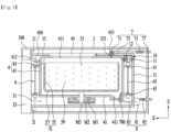
- the clothing processing device 100 of the present invention may include a cabinet 2, a drawer 3 arranged to be withdrawable from the cabinet, a tub 4 arranged in the drawer to store water, and a drum 5 rotatably arranged in the tub to store clothes.
- the drawer body 31 may be inserted into the cabinet 2 through the opening 21 and have any shape as long as it can provide a space for accommodating the tub 4.
- FIG. 1 shows an example of the drawer body 31 which has a hexahedron shape with a hollow interior.
- the tub 4 includes a tub body 41 positioned in the drawer body 31 to store water, and a tub cover 43 for defining the top surface of the tub body 41.
- the tub body 41 may have a cylindrical shape with an open top.
- a heater 411 for heating water may be provided in the tub body 41. The heater 411 may not only heat water but also generate steam to supply steam into the tub body 41.
- connection portion 65 may include a first connection portion 651 seated on the first support portion 61, a second connection portion 653 for supporting the second support portion 63, and a bar 655 for connecting the first connection portion and the second connection portion.
- At least three tub support portions 6 are provided to couple the tub body 41 with the drawer body 31, and the bar 655 is arranged to form a right angle with the bottom surface of the cabinet. Accordingly, the spacing between the tub cover 43 and the drawer cover 35 may be widened, compared to a case where the bar 655 is inclined at a predetermined angle with respect to the Z axis.
- At least one of the first support portion 61 and the second support portion 63 may be detachably attached to the drawer body 31.
- the tub support portion 6 has at least three support portion and both the first support portion 61 and the second support portion 63 are arranged so as not to be separated from the drawer body 31, an operator who fixes the drawer body 31 to the drawer body 31 needs to insert the tub body 41 into the drawer body 31 such that the first support portion 61 does not interfere with the second support portion 63 and then rotate the tub body 41 to position the first connection portion 651 on the vertical line passing through the first support portion 61 to couple the first connection portion 651 to the first support portion 61.
- Arranging the bar 655 of the tub support portion at a right angle with respect to the bottom surface of the drawer may minimize the spacing S between the outer circumferential surface of the tub body 41 and the inner circumferential surface of the drawer body 31, thereby minimizing the volume of the clothing processing device 100.
- Such arrangement may deteriorate assemblability of the first connection portion 651 and the first support portion 61 which are connected through the above-described process. This disadvantage may be overcome by detachably providing the first support portion 61 to the drawer body 31.
- the drum body 51 is rotated in the tub body 41 by a drive unit M.
- the drive unit M may include a stator M1 disposed outside the tub body 41 and fixed to the bottom surface the tub body, a rotor M2 rotated by a rotating field provided by the stator, and a rotary shaft M3 arranged to penetrate the bottom surface of the tub body 41 to connect the bottom surface 57 of the drum and the rotor M3.
- the rotary shaft M3 may be arranged to form a right angle to the bottom surface of the tub body 41.
- the clothing processing device 100 having the above-described structure supplies water to the tub 4 through a water supply unit 7 and discharges water stored in the tub 4 to the outside of the cabinet 2 through a drainage unit 8.
- the drainage unit 8 may include a drain pump 81 fixed to the drawer body 31, a first drain pipe 83 for guiding water from the tub body 41 to the drain pump 81, and a second water supply pipe 85 for guiding the water discharged from the drain pump 81 to the outside of the cabinet 2.
- the second drain pipe 85 may be provided as a corrugated tube.
- tub through hole 412 is provided at the lower end of the tub 4 or the detergent box 300 is arranged at the position of the bottom surface of the tub 4, water may be supplied to the detergent box 300 immediately after water is supplied to the tub 4 through the water supply unit 7, and the detergent in the detergent box 300 may be constantly discharged to the tub 4.
- connection portion 400 is arranged to allow the upper end of the tub body 41 to communicate with the lower end of the detergent box 300 therethrogh.
- the detergent box 300 may be provided on one side of the upper end of the drawer panel 33 to avoid interference with the display unit 331 and may be arranged above the maximum water level of water accommodated in the tub body 41.
- the inside of the detergent box 300 may be opened when the lid 313 is pulled up or rotated.
- the detergent box 300 may be arranged at a position higher than the maximum level of water accommodated in the tub body 41 without any other device, and the connection portion 400 may be arranged at the lower end of the detergent box 300.
- the detergent stored in the detergent box 300 is a liquid detergent
- the detergent may be introduced into the tub 4 through the connection portion 400 irrespective of whether the drum 5 is rotated.
- the detergent box 300 may have a structure which discharges water and the detergent from the detergent box 300 to the connection pipe 400 using the siphon effect when water more than a reference amount is introduced through the connection portion 400.
- the body portion 320 may be stably accommodated in the housing 310,
- Water rising along the side surface of the housing 310 may flow into the opening 323 of the body portion 320.
- the first rpm may be defined as an rpm at which the water accommodated in the tub 4 rises up to the tub through hole 412 provided in the tub body 41.
- the tub through hole 412 may be provided at a position where water contacts the tub body 41 when the drum 5 rotates at the first rpm.
- the water level that water introduced into the housing 310 reaches when the drum 5 rotates at the second rpm may be defined as a first (1st) level.
- the water in the tub 4 flows into the housing 310 through the connection portion 400 and rises up to the free end of the discharge pipe 321. That is, the water supplied to the housing 310 comes into contact with the discharge pipe cover 322.
- the detergent is stored at a second (2nd) level that is higher than the first level and lower than the free end of the discharge pipe 321 or the upper end portion of the discharge pipe cover 322.
- the water and the detergent are mixed, and the level of the water and detergent in the body portion 310 further rises up to a third (3rd) level corresponding to the free end of the discharge pipe 321 or the upper end portion of the discharge pipe cover.
- the water accommodated in the body portion 310 begins to be discharged through the free end of the discharge pipe 321 via the inner circumferential surface of the discharge pipe cover 322 and the outer circumferential surface of the discharge pipe 321.
- the siphon effect occurs, and thus the detergent and water accommodated in the body 310 are entirely discharged to the housing 310 through the discharge pipe 321.
- the water and the detergent accommodated in the housing 310 are discharged to the tub 4 through the connection portion 400 via the housing through hole 311.
- the detergent box 300 may be automatically supplied with water from the tub 4 and discharge the supplied water to the tub 4 without any means for supplying water through the water supply pipe or a control means for controlling discharge of the detergent.
- the side surface of the housing 310 may be arranged higher than the opening 323.
- the body check valve 324 may be a buoyancy type check valve having a specific gravity less than that of water.
- the water supplied to the housing 310 reaches the first (1st) level, and buoyancy may be applied to the body check valve 324 to close the discharge pipe 321. Thereafter, when the drum 5 starts to rotate at the third rpm or a higher speed, the water supplied to the housing 310 may begin to rise along the outer circumferential surface of the body portion 320 and flow into the body portion 320 through the opening 323.
- the tub cover 43 may include a cover body 434 positioned at the top of the tub body 41 to form a top surface of the tub body 41, and an insertion portion 435 protruding from an outer circumferential surface of the cover body 434 and contacting the inner circumferential surface of the tub body 41.
- the insertion portion 435 may be spaced apart from the first fastening portion 437 so as to face the center of the tub 4 and protrude toward the bottom surface of the tub 4.
- the insertion portion 435 may be spaced apart from the tub body 41 by a predetermined distance so as to face the position where the drum 5 is arranged in the tub body 41 and may protrude to a distance long enough to shield the tub through hole 412.
- the insertion portion 435 may block the swell, thereby preventing water from being discharged from the tub through hole 412.
- FIG. 7 shows a resistive rib that may be provided to the tub body 41 to cause water to be supplied to the detergent box 300 only by a constant water level rise in the tub 4 generated by rotation of the drum 5.
- the first resistive ribs 413 may prevent the water accommodated in the tub 4 from unintentionally flowing into the tub through hole 412 and moving to the detergent box 300.
- the inner circumferential surface of the tub may further include a second resistive rib 414 arranged under the tub through hole 412 and protruding toward the bottom surface of the tub.
- the second resistive rib 414 may be arranged in parallel with the first resistive ribs 413.
- the first resistive ribs 413 and the second resistive rib 414 may collide with water moving in contact with the tub body 41 to reduce the kinetic energy of the water, and may also serve to hold a part of the water so as not to rotate, using the surface tension.
- the first resistive ribs 413 and the second resistive rib 414 may effectively prevent the water from being discharged into the tub through hole 412.
- first resistive ribs 413 and the second resistive rib 414 may allow the water to be supplied to the detergent box 300 only when the drum 5 persistently rotates at the first rpm or a higher speed. Accordingly, the rpm of the drum 5 may be precisely controlled to allow water to flow into the detergent box 300 at an appropriate time to supply the detergent to the tub 4.
- the body portion 320 and the housing 310 are detachably provided to the detergent box 300 shown in FIG. 4 , there may be a certain gap between the body portion 320 and the housing 310.
- the siphon effect is persistently maintained in the discharge pipe 321 and the detergent and the water are discharged together to the discharge pipe 321 until the water comes into contact with the outlet portion of the discharge pipe 321, which is immediately before the first (1st) level.
- a pressure change temporarily occurs at the lower end (outlet) of the discharge pipe 321, and the siphon effect is interrupted.
- the interrupted siphon effect occurs again when the water level in the housing 310 falls to or below the first (1st) level and the pressure at the lower end of the discharge pipe 321 remains unchanged.
- the amount of fluid discharged by the siphon effect is smaller than before the siphon effect was interrupted, and accordingly a certain amount of detergent and water may be retained in the body 310.
- the restarted siphon effect is weaker than the siphon effect before the interruption, and thus a certain amount of water and detergent remains in the body portion 320.
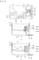
- FIG. 8 illustrates an embodiment of the invention in which a block unit is additionally provided to prevent water supplied into the housing 310 from contacting the lower end of the discharge pipe 321.
- the detergent 300 includes a body portion 312 configured to provide a space for storing a detergent and having an opening at the top thereof, a housing 310 in which the body portion is detachably accommodated, a housing through hole 311 penetrating a lower portion of the housing such that water is introduced or the detergent and water are discharged together therethrough, a discharge pipe 321 protruding from a lower portion of the body toward the opening and provided therein with a hollow for discharging the detergent, and a discharge pipe cover 322 into which a part of the discharge pipe is inserted to guide water and the detergent into the hollow when the amount of water introduced into the body portion is greater than or equal to a reference amount.
- the detergent box further includes a block unit configured to communicate with the discharge pipe 321 and provide a certain space between the lower portion of the body portion 320 and the bottom surface of the housing 310 to prevent water introduced into the housing 310 from contacting the discharge pipe 321.
- the block unit 330 includes a block body 331 accommodated in the housing 310, at least a part of the body portion 320 being accommodated in the block body, and a block through hole 332 formed in a bottom surface of the block body 331 such that the detergent discharged from the discharge pipe 321 is discharged into the housing 310.
- the block unit 330 further includes a block check valve 333 arranged outside the bottom surface of the block body 331 to shield the block through hole 332.
- the block check valve 333 may be a buoyancy type check valve. Thus, when the water in the housing 310 is introduced and brought into contact with the block check valve 333, the block check valve 333 may close the block through hole 332.
- the block check valve 333 may be hinged to the lower surface of the block body 331 or may be fixedly arranged.
- the block check valve 333 may be coupled in any structure as along as it keeps the block through hole 332 open at normal times and is caused to close the block through hole 332 by buoyancy when water is introduced into the housing 310 and brought into contact with the block check valve.
- the block check valve 333 may be made of a rubber material.
- a body coupling portion 325 may be provided to the lower end of the body portion 320, and a block coupling portion 336 capable of being coupled with the body coupling portion 325 may be provided on the bottom surface of the block unit 330.
- the block coupling portion 336 may be formed as a groove into which the body coupling portion 325 is press-fitted.
- the block body 331 may accommodate the body portion 320 from the outside and provide a predetermined space between the bottom surface of the body portion 320 and the bottom surface of the block body 331, such that water introduced into the housing 310 may be prevented from flowing into the predetermined space.
- the block body 331 may be configured such that only air can be contained in the space between the lower surface of the body portion 320 and the bottom surface of the block body, and the water supplied into the housing 310 cannot be introduced into the space.
- the drum 5 is rotated at a speed higher than or equal to the first rpm and lower than or equal to the second rpm, and thus water starts to flow into the housing 310.
- water introduced into the housing 310 starts to further rise in the housing 310 and pushes up the block check valve 333 to close the lower end (outlet) of the discharge port 321.
- the drum 5 is rotated at a speed higher than the third rpm, and thus water introduced into the housing 310 flows into the body 310 through the opening 323 and is supplied until the water reaches the third (3rd) level.
- the siphon effect occurs in the discharge pipe 321, and thus the detergent and water in the body portion 310 are discharged to the block unit 330.
- the detergent and water discharged to the block unit 330 press the check valve 333 by their own weights. Then, when the water level in the housing 310 is lowered, the check valve 333 is opened, and both the water and the detergent in the block unit 330 are discharged to the tub 4 through the first connection pipe 410 via the housing through hole 311.
- the water and detergent may be entirely discharged to the tub 4 by the block unit 330 without any water or detergent remaining in the body 310.
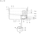
- FIG. 10 illustrates another embodiment of the block unit 330.
- the block unit 330 of FIG. 10 does not fully accommodate the body portion 310, unlike the block unit of FIG. 9 , but is configured to accommodate only a part of the body portion that is provided with the discharge pipe 321.
- the block unit 330 may include a block barrel 334 extending from a lower end of the body portion 320 having the discharge pipe 321.
- the block barrel 334 may include a communication hole provided at one end to communicate with the discharge pipe 321 and a block through hole 332 provided at an opposite end to communicate with the housing 310.
- a block check valve 333 configured to open and close the block through hole 332 may be provided on the outer circumferential surface of the block through hole 332.
- the block unit 330 shown in FIG. 10 may prevent change in pressure at the outlet (lower end) of the discharge pipe 321 to prevent the discharge pipe 321 from making a direct contact with water introduced into the housing 310.
- the water introduced into the housing 310 may raise the block check valve 333 to close the block through hole 332 and may flow into the opening 323 to generate and persistently maintain the siphon effect in the discharge pipe 321.
- the block unit 330 may cause all the water and detergent in the body portion 310 to be discharged to the housing 310.
- the clothing processing device of the present invention may include a water supply step S1 of supplying water to the tub 4, a washing step S2 of rotating the drum 5 at an rpm lower than the first rpm, and a detergent box water supply step S3 of rotating the drum at an rpm higher than or equal to the first rpm to move a part of water stored in the tub corresponding to a reference amount or a larger amount to the detergent box 300, the detergent box water supply step being initiated before or during the washing step.
- the first rpm is set to an rpm at which centrifugal force causing at least a part of the water stored in the tub 4 to rise up even in the detergent box through the connection portion 400 is provided to the water.
- a third rpm which is higher than the first rpm, may be set as an rpm at which the siphon effect occurs in the detergent box.
- the rpm higher than or equal to the first rpm may correspond to an rpm higher than or equal to the third rpm.
- the reference amount may be set to the amount of water at which the siphon effect starts to occur in the detergent box.
- the washing step may include a first washing step S2-1 of rotating the drum 5 at an rpm lower than the first rpm to create a water stream in the tub, a drainage step S2-2 of discharging the water stored in the tub 4 after completion of the first washing step, a second water supply step S2-3 of supplying water to the tub 5 after completion of the drainage step, and a second washing step S2-4 of rotating the drum at an rpm lower than the first rpm to create a water stream in the tub.
- the detergent box water supply step S3 may include a step of determining a time at which the detergent can be introduced into the tub 4, and then supplying the detergent to the tub 4 when the time is reached.
- the time at which the detergent can be introduced into the tub 4 may be a time before the first washing step S2-1 is initiated if a detergent for removing foreign substances from clothes is accommodated in the detergent box 300, or correspond to the second washing step S2-3 if a fabric softener for increasing the degree of flexibility of the clothes is accommodated in the detergent box 300.
- the water supply step S1 is a step of supplying water to the tub 4 such that a water level higher than the bottom surface of the drum 5 is maintained.
- the detergent box water supply step S3 may be performed before the first washing step S2-2 is initiated after completion of the water supply step.
- the detergent box water supply step S3 is performed before initiation of the first washing step when the detergent box 300 contains the detergent, the detergent may be supplied to the tub 4 before the first washing step S2-1. Accordingly, foreign substances may be removed from the clothes with the detergent and water in the first washing step S2-1.
- the first washing step S2-1 may be understood as a step of separating foreign substances from the clothes using the detergent stored in the detergent box 300.
- the second water supply step S2-3 is a step of supplying water to the tub again such that a water level higher than the bottom surface of the drum is maintained.
- the second water supply step S2-3 may be understood as a step of supplying water for the rinsing cycle of washing away the detergent and foreign substances from the clothes.
- the detergent box water supply step S3 may be performed before the second washing step S2-4 is initiated after completion of the second water supply step S2-3.
- the second washing step S2-4 may be provided as a step of supplying the fabric softener stored in the detergent box to the tub to increase the degree of flexibility of the clothes.
- the second washing step S2-4 may be set as a step of increasing the degree of flexibility of the clothes by supplying the detergent stored in the detergent box to the tub.
- the clothing processing device 100 of the present invention may omit the water supplying means which communicates with the water supply unit 7 to separately supply water to the detergent box 300. That is, the detergent contained in the detergent box 300 may be automatically discharged to the tub 4 by controlling the rpm of the drum 5 alone in order to separate foreign substances from the clothes or to increase the degree of flexibility of the clothes.
Landscapes
- Engineering & Computer Science (AREA)
- Textile Engineering (AREA)
- Detail Structures Of Washing Machines And Dryers (AREA)
- Main Body Construction Of Washing Machines And Laundry Dryers (AREA)
Claims (8)
- Waschmittelbehälter (300) für eine Wäschebehandlungsvorrichtung (100), aufweisend:einen Körperabschnitt (320), der einen Raum zum Unterbringen von Waschmittel bereitstellt und eine Öffnung (323) an seiner Oberseite aufweist;ein Gehäuse (310), in dem der Körperabschnitt (320) abnehmbar aufgenommen werden kann;ein Gehäusedurchgangsloch (311), das durch einen unteren Abschnitt des Gehäuses (310) hindurch ausgebildet ist, damit Wasser lediglich aus einem Bottich (4) der Wäschebehandlungsvorrichtung (100) darin eingeleitet werden kann oder das Wasser und das Waschmittel zusammen abgeleitet werden können;ein Auslassrohr (321), das von einem unteren Abschnitt des Körperabschnitts (320) in Richtung der Öffnung (323) vorsteht und einen Hohlraum zum Auslassen des Waschmittels aufweist; undeine Auslassrohrabdeckung (322), die dazu ausgelegt ist, das Wasser und das Waschmittel in den Hohlraum zu leiten, wenn eine Referenzmenge oder eine größere Menge an Wasser in den Körperabschnitt (320) einströmt, wobei zumindest ein Teil des Auslassrohrs (321) in die Auslassrohrabdeckung (322) eingesetzt ist,wobei der Waschmittelbehälter (300) ferner eine Sperreinheit (330) aufweist, die mit dem Auslassrohr (321) in Verbindung steht und einen vorbestimmten Raum zwischen einem unteren Abschnitt des Körperabschnitts (320) und einer Bodenfläche des Gehäuses (310) aufweist, um zu verhindern, dass in das Gehäuse (310) eingeleitetes Wasser in das Auslassrohr (321) strömt, undwobei dann, wenn der Körperabschnitt (320) in dem Gehäuse (310) aufgenommen ist, eine äußere Umfangsfläche des Körperabschnitts (320) und eine Seitenfläche des Gehäuses (310) um einen vorbestimmten Abstand voneinander beabstandet sind, und die Seitenfläche des Gehäuses (310) an einer höher liegenden Stelle als die Öffnung (323) angeordnet ist, so dass in das Gehäuse (310) eingeleitetes Wasser durch die Öffnung (323) entlang der äußeren Umfangsfläche des Körperabschnitts (320) in den Körperabschnitt (320) einströmt,wobei die Sperreinheit (330) aufweist:einen Sperrkörper (331), der in dem Gehäuse (310) aufgenommen ist, wobei zumindest ein Teil des Körperabschnitts (320) in dem Sperrkörper (331) aufgenommen ist; undein Sperrdurchgangsloch (332), das in einer Bodenfläche des Sperrkörpers (331) ausgebildet ist, so dass das aus dem Auslassrohr (321) ausgelassene Waschmittel in das Gehäuse (310) ausgelassen wird, undwobei vorzugsweise die Sperreinheit (330) ferner aufweist:
ein Sperrrückschlagventil (333), das außerhalb der Bodenfläche des Sperrkörpers (331) angeordnet ist, um das Sperrdurchgangsloch (332) abzuschirmen. - Waschmittelbehälter (300) nach Anspruch 1, wobei das Sperrrückschlagventil (333) ein Rückschlagventil mit Auftrieb ist, dessen spezifisches Gewicht geringer als das spezifische Gewicht von Wasser ist, und wobei das Sperrrückschlagventil (333) aus einem Gummimaterial hergestellt ist.
- Waschmittelbehälter (300) nach Anspruch 1 oder 2, wobei die Sperreinheit (330) aufweist:einen Sperrzylinder (334), der sich ausgehend von einem das Auslassrohr (321) aufweisenden unteren Ende des Körperabschnitts (320) erstreckt,wobei der Sperrzylinder (334) ein Verbindungsloch aufweist, das an einem Ende vorgesehen ist, um mit dem Auslassrohr (321) zu kommunizieren, sowie das Sperrdurchgangsloch (332), das an einem gegenüberliegenden Ende vorgesehen ist, um mit dem Gehäuse (310) zu kommunizieren.
- Wäschebehandlungsvorrichtung (100), umfassend:einen Waschmittelbehälter (300) nach einem der Ansprüche 1 bis 3;einen Bottich (4), der einen Raum zum Aufnehmen von Wasser bereitstellt;eine Trommel (5), die drehbar in dem Bottich (4) angeordnet ist, um einen Raum zum Aufnehmen von Kleidung bereitzustellen;ein Bottichdurchgangsloch (412), das durch eine innere Umfangsfläche des Bottichs (4) hindurch ausgebildet ist;wobei der Waschmittelbehälter (300) außerhalb des Bottichs (4) angeordnet ist, um einen Raum zum Aufnehmen von Waschmittel bereitzustellen; undwobei die Wäschebehandlungsvorrichtung (100) ferner einen Verbindungsabschnitt (400) aufweist, der auf seiner einen Seite mit dem Bottichdurchgangsloch (412) und auf seiner gegenüberliegenden Seite mit dem Waschmittelbehälter (300) in Verbindung steht, so dass zumindest ein Teil des Wassers, der sich aufgrund der bei Drehung der Trommel (5) erzeugten Zentrifugalkraft entlang einer inneren Umfangsfläche des Bottichs (4) bewegt, in den Waschmittelbehälter (300) eingeleitet, mit dem Waschmittel vermischt und dann zurück zu der inneren Umfangsfläche des Bottichs (4) abgeleitet wird.
- Wäschebehandlungsvorrichtung (100) nach Anspruch 4, wobei der Waschmittelbehälter (300) an einer Stelle angeordnet ist, die höher liegt als ein maximaler Wasserpegel des Wassers, das in dem Bottich (4) aufgenommen werden kann, wenn die Trommel (5) angehalten ist, und wobei dann, wenn eine durch den Verbindungsabschnitt (400) in den Waschmittelbehälter (300) eingeleitete Wassermenge größer oder gleich einer Referenzmenge ist, der Waschmittelbehälter (300) das Waschmittel und das Wasser unter Verwendung eines Siphoneffekts aus dem Waschmittelbehälter (300) zurück zum Verbindungsrohr (410) ableitet.
- Wäschebehandlungsvorrichtung (100) nach Anspruch 5, wobei das Wasser in dem Bottich (4) nur dann zu dem Verbindungsabschnitt (400) abgeleitet und durch Zentrifugalkraft in den Waschmittelbehälter (300) eingeleitet wird, wenn sich die Trommel (5) mit einer Geschwindigkeit dreht, die größer oder gleich einer ersten Drehzahl (U/min) ist, und wobei das Bottichdurchgangsloch (412) an einem Wasserpegel vorgesehen ist, der von dem Wasser in dem Bottich (4) erreicht wird, wenn sich die Trommel (5) mit der ersten Drehzahl dreht.
- Wäschebehandlungsvorrichtung (100) nach einem der Ansprüche 4 bis 6, wobei die innere Umfangsfläche des Bottichs (4) mit ersten Widerstandsrippen (413) versehen ist, die von beiden Seiten einer mit dem Bottichdurchgangsloch (412) versehenen Fläche vorstehen, um einen Widerstand gegen Wasser zu erzeugen, das an der inneren Umfangsfläche des Bottichs (4) rotiert, so dass das Wasser nur dann in das Bottichdurchgangsloch (412) einströmt, wenn sich die Trommel (5) mit einer Geschwindigkeit dreht, die größer oder gleich einer Referenzdrehzahl (U/min) ist, und wobei vorzugsweise die Innenfläche des Bottichs (4) mit einer zweiten Widerstandsrippe (414) versehen ist, die unter dem Bottichdurchgangsloch (412) angeordnet ist, um in Richtung einer Bodenfläche des Bottichs (4) vorzustehen.
- Wäschebehandlungsvorrichtung (100) nach einem der Ansprüche 4 bis 7, wobei die Wäschebehandlungsvorrichtung (100) ferner aufweist:einen Ausziehkörper (31) zum Aufnehmen der Bottichs (4) und der Trommel (5); undeine Ausziehblende (33), die an dem Ausziehkörper (31) angeordnet ist, um die Öffnung (323) zu öffnen und zu schließen,wobei der Waschmittelbehälter (300) an der Ausziehblende (33) vorgesehen ist.
Applications Claiming Priority (2)
| Application Number | Priority Date | Filing Date | Title |
|---|---|---|---|
| KR1020160149418A KR20180052282A (ko) | 2016-11-10 | 2016-11-10 | 세제박스 및 이를 구비한 의류처리장치 |
| PCT/KR2017/012655 WO2018088814A1 (ko) | 2016-11-10 | 2017-11-09 | 세제박스 및 이를 구비한 의류처리장치 |
Publications (3)
| Publication Number | Publication Date |
|---|---|
| EP3540112A1 EP3540112A1 (de) | 2019-09-18 |
| EP3540112A4 EP3540112A4 (de) | 2020-07-08 |
| EP3540112B1 true EP3540112B1 (de) | 2025-01-01 |
Family
ID=62110652
Family Applications (1)
| Application Number | Title | Priority Date | Filing Date |
|---|---|---|---|
| EP17868982.4A Active EP3540112B1 (de) | 2016-11-10 | 2017-11-09 | Reinigungsmittelbox und dazugehörige bekleidungsverarbeitungsvorrichtung |
Country Status (5)
| Country | Link |
|---|---|
| US (1) | US11021832B2 (de) |
| EP (1) | EP3540112B1 (de) |
| KR (1) | KR20180052282A (de) |
| CN (1) | CN109923258B (de) |
| WO (1) | WO2018088814A1 (de) |
Families Citing this family (6)
| Publication number | Priority date | Publication date | Assignee | Title |
|---|---|---|---|---|
| DE102017121877A1 (de) * | 2017-09-21 | 2019-03-21 | Miele & Cie. Kg | Saugheber für einen Einspülkasten einer Waschmaschine |
| KR20220046897A (ko) | 2020-10-08 | 2022-04-15 | 엘지전자 주식회사 | 의류처리장치 |
| CN114525655B (zh) * | 2022-02-17 | 2023-04-25 | 珠海格力电器股份有限公司 | 一种洗涤剂盒的液位检测装置、控制方法及洗衣机 |
| US12331451B2 (en) | 2022-02-21 | 2025-06-17 | Haier Us Appliance Solutions, Inc. | Dryer appliance and compartment for non-tumbling items |
| CN115506125A (zh) * | 2022-09-23 | 2022-12-23 | 创维电器股份有限公司 | 一种带自动投放的迷你波轮洗衣机 |
| US12410550B2 (en) | 2022-11-28 | 2025-09-09 | Haier Us Appliance Solutions, Inc. | Laundry appliance door for treatment of non-moving articles |
Family Cites Families (14)
| Publication number | Priority date | Publication date | Assignee | Title |
|---|---|---|---|---|
| US4467627A (en) * | 1982-12-16 | 1984-08-28 | Whirlpool Corporation | Pump for a dispensing system for an automatic washer |
| KR19990016521U (ko) * | 1997-10-28 | 1999-05-25 | 전주범 | 세탁기의 세제 공급장치 |
| US6826933B2 (en) * | 2002-02-06 | 2004-12-07 | Maytag Corporation | Dual use detergent dispenser |
| KR20060111286A (ko) * | 2005-04-22 | 2006-10-27 | 삼성전자주식회사 | 헹굼제 투입장치를 갖춘 세탁기 및 그 제어방법 |
| CN101177896B (zh) * | 2006-11-08 | 2011-06-08 | 南京乐金熊猫电器有限公司 | 一种洗涤装置的洗涤剂供给机构 |
| KR101698310B1 (ko) * | 2009-12-24 | 2017-01-20 | 삼성전자주식회사 | 세제공급장치 및 이를 가지는 세탁기 |
| KR20120073577A (ko) * | 2010-12-27 | 2012-07-05 | 주식회사 대우일렉트로닉스 | 세탁기용 세제투입장치 |
| CN202023088U (zh) * | 2011-04-07 | 2011-11-02 | 合肥荣事达三洋电器股份有限公司 | 速溶洗衣粉盒的进水装置 |
| KR101812171B1 (ko) * | 2011-09-02 | 2017-12-26 | 엘지전자 주식회사 | 세탁장치 |
| KR101970247B1 (ko) * | 2012-09-04 | 2019-04-18 | 엘지전자 주식회사 | 첨가제투입장치 및 그를 포함하는 세탁물 처리기기 |
| KR101993223B1 (ko) * | 2012-10-10 | 2019-06-26 | 엘지전자 주식회사 | 의류처리장치 |
| WO2015002413A1 (ko) * | 2013-07-03 | 2015-01-08 | 삼성전자주식회사 | 세제공급장치 및 이를 갖는 세탁기 |
| KR20150025083A (ko) * | 2013-08-28 | 2015-03-10 | 엘지전자 주식회사 | 의류처리장치 |
| BR112016011867B1 (pt) * | 2013-11-28 | 2022-01-11 | Lg Electronics Inc. | Máquina de lavar |
-
2016
- 2016-11-10 KR KR1020160149418A patent/KR20180052282A/ko not_active Withdrawn
-
2017
- 2017-11-09 CN CN201780068633.8A patent/CN109923258B/zh active Active
- 2017-11-09 EP EP17868982.4A patent/EP3540112B1/de active Active
- 2017-11-09 WO PCT/KR2017/012655 patent/WO2018088814A1/ko not_active Ceased
- 2017-11-09 US US16/349,125 patent/US11021832B2/en not_active Expired - Fee Related
Also Published As
| Publication number | Publication date |
|---|---|
| KR20180052282A (ko) | 2018-05-18 |
| CN109923258B (zh) | 2021-06-22 |
| US20190276974A1 (en) | 2019-09-12 |
| CN109923258A (zh) | 2019-06-21 |
| WO2018088814A1 (ko) | 2018-05-17 |
| EP3540112A4 (de) | 2020-07-08 |
| US11021832B2 (en) | 2021-06-01 |
| EP3540112A1 (de) | 2019-09-18 |
Similar Documents
| Publication | Publication Date | Title |
|---|---|---|
| US11280038B2 (en) | Laundry treating apparatus and method for controlling laundry treating apparatus | |
| US11021832B2 (en) | Detergent box and laundry treating apparatus including same | |
| KR20180053189A (ko) | 의류처리장치 | |
| KR102322514B1 (ko) | 세탁물 처리기기 | |
| EP3553221B1 (de) | Wäschebehandlungsvorrichtung und verfahren zur steuerung davon | |
| KR101276818B1 (ko) | 보조 건조기 및 이를 포함하는 복합 세탁장치 | |
| KR102060067B1 (ko) | 의류처리장치 및 그 제어방법 | |
| KR101435811B1 (ko) | 의류처리장치 | |
| EP3543393A2 (de) | Kleidungsbehandlungsvorrichtung | |
| KR102303656B1 (ko) | 세탁 건조기 및 그 제어방법 | |
| JP6437502B2 (ja) | 洗濯機及び洗濯機の制御方法 | |
| EP3138949B1 (de) | Wäschebehandlungsvorrichtung mit ablaufstutzen | |
| EP1899522A1 (de) | Waschmaschine | |
| US20200131687A1 (en) | Scent dispensing assembly for a washing machine appliance | |
| KR20170039995A (ko) | 세탁기 | |
| CN103492627A (zh) | 滚筒式洗衣机 | |
| EP3995619A1 (de) | Steuerungsverfahren für eine waschmaschine | |
| KR100835357B1 (ko) | 세탁기 및 그 거품세탁방법 | |
| KR102649021B1 (ko) | 의류처리장치 및 그것의 제어방법 | |
| KR102318548B1 (ko) | 의류처리장치의 제어방법 | |
| JP6609442B2 (ja) | 自動洗濯機 | |
| KR101320671B1 (ko) | 페데스탈 세탁기 및 그 제어방법 | |
| KR102017708B1 (ko) | 의류처리장치 및 그 제어방법 | |
| KR20020080637A (ko) | 세탁기 | |
| KR20180035767A (ko) | 세탁기 |
Legal Events
| Date | Code | Title | Description |
|---|---|---|---|
| STAA | Information on the status of an ep patent application or granted ep patent |
Free format text: STATUS: THE INTERNATIONAL PUBLICATION HAS BEEN MADE |
|
| PUAI | Public reference made under article 153(3) epc to a published international application that has entered the european phase |
Free format text: ORIGINAL CODE: 0009012 |
|
| STAA | Information on the status of an ep patent application or granted ep patent |
Free format text: STATUS: REQUEST FOR EXAMINATION WAS MADE |
|
| 17P | Request for examination filed |
Effective date: 20190607 |
|
| AK | Designated contracting states |
Kind code of ref document: A1 Designated state(s): AL AT BE BG CH CY CZ DE DK EE ES FI FR GB GR HR HU IE IS IT LI LT LU LV MC MK MT NL NO PL PT RO RS SE SI SK SM TR |
|
| AX | Request for extension of the european patent |
Extension state: BA ME |
|
| DAV | Request for validation of the european patent (deleted) | ||
| DAX | Request for extension of the european patent (deleted) | ||
| A4 | Supplementary search report drawn up and despatched |
Effective date: 20200609 |
|
| RIC1 | Information provided on ipc code assigned before grant |
Ipc: D06F 39/02 20060101AFI20200603BHEP Ipc: D06F 103/18 20200101ALN20200603BHEP Ipc: D06F 33/37 20200101ALI20200603BHEP Ipc: D06F 23/04 20060101ALN20200603BHEP Ipc: D06F 37/26 20060101ALN20200603BHEP Ipc: D06F 105/42 20200101ALN20200603BHEP Ipc: D06F 103/24 20200101ALN20200603BHEP |
|
| STAA | Information on the status of an ep patent application or granted ep patent |
Free format text: STATUS: EXAMINATION IS IN PROGRESS |
|
| 17Q | First examination report despatched |
Effective date: 20221012 |
|
| GRAP | Despatch of communication of intention to grant a patent |
Free format text: ORIGINAL CODE: EPIDOSNIGR1 |
|
| STAA | Information on the status of an ep patent application or granted ep patent |
Free format text: STATUS: GRANT OF PATENT IS INTENDED |
|
| RIC1 | Information provided on ipc code assigned before grant |
Ipc: D06F 105/42 20200101ALN20240620BHEP Ipc: D06F 103/24 20200101ALN20240620BHEP Ipc: D06F 103/18 20200101ALN20240620BHEP Ipc: D06F 37/26 20060101ALN20240620BHEP Ipc: D06F 23/04 20060101ALN20240620BHEP Ipc: D06F 39/02 20060101AFI20240620BHEP |
|
| INTG | Intention to grant announced |
Effective date: 20240705 |
|
| GRAS | Grant fee paid |
Free format text: ORIGINAL CODE: EPIDOSNIGR3 |
|
| GRAA | (expected) grant |
Free format text: ORIGINAL CODE: 0009210 |
|
| STAA | Information on the status of an ep patent application or granted ep patent |
Free format text: STATUS: THE PATENT HAS BEEN GRANTED |
|
| AK | Designated contracting states |
Kind code of ref document: B1 Designated state(s): AL AT BE BG CH CY CZ DE DK EE ES FI FR GB GR HR HU IE IS IT LI LT LU LV MC MK MT NL NO PL PT RO RS SE SI SK SM TR |
|
| REG | Reference to a national code |
Ref country code: GB Ref legal event code: FG4D |
|
| REG | Reference to a national code |
Ref country code: CH Ref legal event code: EP |
|
| REG | Reference to a national code |
Ref country code: DE Ref legal event code: R096 Ref document number: 602017087141 Country of ref document: DE |
|
| REG | Reference to a national code |
Ref country code: IE Ref legal event code: FG4D |
|
| REG | Reference to a national code |
Ref country code: LT Ref legal event code: MG9D |
|
| REG | Reference to a national code |
Ref country code: NL Ref legal event code: MP Effective date: 20250101 |
|
| REG | Reference to a national code |
Ref country code: AT Ref legal event code: MK05 Ref document number: 1756335 Country of ref document: AT Kind code of ref document: T Effective date: 20250101 |
|
| PG25 | Lapsed in a contracting state [announced via postgrant information from national office to epo] |
Ref country code: NL Free format text: LAPSE BECAUSE OF FAILURE TO SUBMIT A TRANSLATION OF THE DESCRIPTION OR TO PAY THE FEE WITHIN THE PRESCRIBED TIME-LIMIT Effective date: 20250101 |
|
| PG25 | Lapsed in a contracting state [announced via postgrant information from national office to epo] |
Ref country code: FI Free format text: LAPSE BECAUSE OF FAILURE TO SUBMIT A TRANSLATION OF THE DESCRIPTION OR TO PAY THE FEE WITHIN THE PRESCRIBED TIME-LIMIT Effective date: 20250101 |
|
| PG25 | Lapsed in a contracting state [announced via postgrant information from national office to epo] |
Ref country code: PL Free format text: LAPSE BECAUSE OF FAILURE TO SUBMIT A TRANSLATION OF THE DESCRIPTION OR TO PAY THE FEE WITHIN THE PRESCRIBED TIME-LIMIT Effective date: 20250101 |
|
| PG25 | Lapsed in a contracting state [announced via postgrant information from national office to epo] |
Ref country code: ES Free format text: LAPSE BECAUSE OF FAILURE TO SUBMIT A TRANSLATION OF THE DESCRIPTION OR TO PAY THE FEE WITHIN THE PRESCRIBED TIME-LIMIT Effective date: 20250101 |
|
| PG25 | Lapsed in a contracting state [announced via postgrant information from national office to epo] |
Ref country code: IS Free format text: LAPSE BECAUSE OF FAILURE TO SUBMIT A TRANSLATION OF THE DESCRIPTION OR TO PAY THE FEE WITHIN THE PRESCRIBED TIME-LIMIT Effective date: 20250501 Ref country code: NO Free format text: LAPSE BECAUSE OF FAILURE TO SUBMIT A TRANSLATION OF THE DESCRIPTION OR TO PAY THE FEE WITHIN THE PRESCRIBED TIME-LIMIT Effective date: 20250401 |
|
| PG25 | Lapsed in a contracting state [announced via postgrant information from national office to epo] |
Ref country code: HR Free format text: LAPSE BECAUSE OF FAILURE TO SUBMIT A TRANSLATION OF THE DESCRIPTION OR TO PAY THE FEE WITHIN THE PRESCRIBED TIME-LIMIT Effective date: 20250101 |
|
| PG25 | Lapsed in a contracting state [announced via postgrant information from national office to epo] |
Ref country code: LV Free format text: LAPSE BECAUSE OF FAILURE TO SUBMIT A TRANSLATION OF THE DESCRIPTION OR TO PAY THE FEE WITHIN THE PRESCRIBED TIME-LIMIT Effective date: 20250101 Ref country code: PT Free format text: LAPSE BECAUSE OF FAILURE TO SUBMIT A TRANSLATION OF THE DESCRIPTION OR TO PAY THE FEE WITHIN THE PRESCRIBED TIME-LIMIT Effective date: 20250502 |
|
| PG25 | Lapsed in a contracting state [announced via postgrant information from national office to epo] |
Ref country code: BG Free format text: LAPSE BECAUSE OF FAILURE TO SUBMIT A TRANSLATION OF THE DESCRIPTION OR TO PAY THE FEE WITHIN THE PRESCRIBED TIME-LIMIT Effective date: 20250101 Ref country code: GR Free format text: LAPSE BECAUSE OF FAILURE TO SUBMIT A TRANSLATION OF THE DESCRIPTION OR TO PAY THE FEE WITHIN THE PRESCRIBED TIME-LIMIT Effective date: 20250402 |
|
| PG25 | Lapsed in a contracting state [announced via postgrant information from national office to epo] |
Ref country code: AT Free format text: LAPSE BECAUSE OF FAILURE TO SUBMIT A TRANSLATION OF THE DESCRIPTION OR TO PAY THE FEE WITHIN THE PRESCRIBED TIME-LIMIT Effective date: 20250101 |
|
| PG25 | Lapsed in a contracting state [announced via postgrant information from national office to epo] |
Ref country code: CZ Free format text: LAPSE BECAUSE OF FAILURE TO SUBMIT A TRANSLATION OF THE DESCRIPTION OR TO PAY THE FEE WITHIN THE PRESCRIBED TIME-LIMIT Effective date: 20250101 |
|
| PG25 | Lapsed in a contracting state [announced via postgrant information from national office to epo] |
Ref country code: SE Free format text: LAPSE BECAUSE OF FAILURE TO SUBMIT A TRANSLATION OF THE DESCRIPTION OR TO PAY THE FEE WITHIN THE PRESCRIBED TIME-LIMIT Effective date: 20250101 |
|
| REG | Reference to a national code |
Ref country code: DE Ref legal event code: R097 Ref document number: 602017087141 Country of ref document: DE |
|
| PG25 | Lapsed in a contracting state [announced via postgrant information from national office to epo] |
Ref country code: SM Free format text: LAPSE BECAUSE OF FAILURE TO SUBMIT A TRANSLATION OF THE DESCRIPTION OR TO PAY THE FEE WITHIN THE PRESCRIBED TIME-LIMIT Effective date: 20250101 |
|
| PG25 | Lapsed in a contracting state [announced via postgrant information from national office to epo] |
Ref country code: DK Free format text: LAPSE BECAUSE OF FAILURE TO SUBMIT A TRANSLATION OF THE DESCRIPTION OR TO PAY THE FEE WITHIN THE PRESCRIBED TIME-LIMIT Effective date: 20250101 |
|
| PG25 | Lapsed in a contracting state [announced via postgrant information from national office to epo] |
Ref country code: IT Free format text: LAPSE BECAUSE OF FAILURE TO SUBMIT A TRANSLATION OF THE DESCRIPTION OR TO PAY THE FEE WITHIN THE PRESCRIBED TIME-LIMIT Effective date: 20250101 |
|
| PG25 | Lapsed in a contracting state [announced via postgrant information from national office to epo] |
Ref country code: EE Free format text: LAPSE BECAUSE OF FAILURE TO SUBMIT A TRANSLATION OF THE DESCRIPTION OR TO PAY THE FEE WITHIN THE PRESCRIBED TIME-LIMIT Effective date: 20250101 |
|
| PG25 | Lapsed in a contracting state [announced via postgrant information from national office to epo] |
Ref country code: RO Free format text: LAPSE BECAUSE OF FAILURE TO SUBMIT A TRANSLATION OF THE DESCRIPTION OR TO PAY THE FEE WITHIN THE PRESCRIBED TIME-LIMIT Effective date: 20250101 |
|
| PG25 | Lapsed in a contracting state [announced via postgrant information from national office to epo] |
Ref country code: SK Free format text: LAPSE BECAUSE OF FAILURE TO SUBMIT A TRANSLATION OF THE DESCRIPTION OR TO PAY THE FEE WITHIN THE PRESCRIBED TIME-LIMIT Effective date: 20250101 |
|
| PLBE | No opposition filed within time limit |
Free format text: ORIGINAL CODE: 0009261 |
|
| STAA | Information on the status of an ep patent application or granted ep patent |
Free format text: STATUS: NO OPPOSITION FILED WITHIN TIME LIMIT |
|
| 26N | No opposition filed |
Effective date: 20251002 |
|
| PGFP | Annual fee paid to national office [announced via postgrant information from national office to epo] |
Ref country code: DE Payment date: 20251002 Year of fee payment: 9 |