EP3539791A1 - Druckbalken für inkjet - Google Patents
Druckbalken für inkjet Download PDFInfo
- Publication number
- EP3539791A1 EP3539791A1 EP18162185.5A EP18162185A EP3539791A1 EP 3539791 A1 EP3539791 A1 EP 3539791A1 EP 18162185 A EP18162185 A EP 18162185A EP 3539791 A1 EP3539791 A1 EP 3539791A1
- Authority
- EP
- European Patent Office
- Prior art keywords
- pressure bar
- bar according
- holder
- print head
- gravity
- Prior art date
- Legal status (The legal status is an assumption and is not a legal conclusion. Google has not performed a legal analysis and makes no representation as to the accuracy of the status listed.)
- Granted
Links
Images


Classifications
-
- B—PERFORMING OPERATIONS; TRANSPORTING
- B41—PRINTING; LINING MACHINES; TYPEWRITERS; STAMPS
- B41J—TYPEWRITERS; SELECTIVE PRINTING MECHANISMS, i.e. MECHANISMS PRINTING OTHERWISE THAN FROM A FORME; CORRECTION OF TYPOGRAPHICAL ERRORS
- B41J25/00—Actions or mechanisms not otherwise provided for
- B41J25/001—Mechanisms for bodily moving print heads or carriages parallel to the paper surface
-
- B—PERFORMING OPERATIONS; TRANSPORTING
- B41—PRINTING; LINING MACHINES; TYPEWRITERS; STAMPS
- B41J—TYPEWRITERS; SELECTIVE PRINTING MECHANISMS, i.e. MECHANISMS PRINTING OTHERWISE THAN FROM A FORME; CORRECTION OF TYPOGRAPHICAL ERRORS
- B41J25/00—Actions or mechanisms not otherwise provided for
- B41J25/001—Mechanisms for bodily moving print heads or carriages parallel to the paper surface
- B41J25/003—Mechanisms for bodily moving print heads or carriages parallel to the paper surface for changing the angle between a print element array axis and the printing line, e.g. for dot density changes
-
- B—PERFORMING OPERATIONS; TRANSPORTING
- B41—PRINTING; LINING MACHINES; TYPEWRITERS; STAMPS
- B41J—TYPEWRITERS; SELECTIVE PRINTING MECHANISMS, i.e. MECHANISMS PRINTING OTHERWISE THAN FROM A FORME; CORRECTION OF TYPOGRAPHICAL ERRORS
- B41J2202/00—Embodiments of or processes related to ink-jet or thermal heads
- B41J2202/01—Embodiments of or processes related to ink-jet heads
- B41J2202/20—Modules
-
- B—PERFORMING OPERATIONS; TRANSPORTING
- B41—PRINTING; LINING MACHINES; TYPEWRITERS; STAMPS
- B41J—TYPEWRITERS; SELECTIVE PRINTING MECHANISMS, i.e. MECHANISMS PRINTING OTHERWISE THAN FROM A FORME; CORRECTION OF TYPOGRAPHICAL ERRORS
- B41J2202/00—Embodiments of or processes related to ink-jet or thermal heads
- B41J2202/01—Embodiments of or processes related to ink-jet heads
- B41J2202/21—Line printing
Definitions
- the present invention relates to a print bar for inkjet comprising printheads in a row, holders each holding a printhead, and aligning means for adjusting the printheads with each other.
- the object of the invention is to provide a pressure bar in which the adjustment of the printheads is possible without the risk of collisions.
- a print bar for inkjet comprising printheads in a row, holders, each holding a printhead, and adjusting means for adjusting the printheads to each other, wherein each printhead has a nozzle surface with a geometric center of gravity, and the print bar is characterized that each printhead is attached to its holder in two attachment points that are adjustable relative to a fixed point of the holder, wherein an imaginary, straight connecting line connects the attachment points, and that the connecting line passes through the center of gravity of the nozzle surface.
- the center of gravity of the nozzle surface not only means the ideal center of gravity, but also a point which lies within an imaginary, circular tolerance range whose Circle center is the ideal center of gravity, wherein the size of the area of the tolerance range is at most 20%, in particular at most 10% and preferably at most 5% of the size of the entire nozzle surface.
- Advantage of the pressure bar according to the invention is that in the adjustment of the respective print head whose rotation about the center of gravity of the nozzle surface is possible, whereby the risk of collision is largely dispelled.
- a first adjusting device and a second adjusting device can rest on the holder per printhead, such that an adjustment of the two adjusting devices in opposite directions causes an adjustment of the printhead in a first degree of freedom and an adjustment of the two adjusting devices that is identical to one another in an adjustment of the printhead in a second degree of freedom.
- the first degree of freedom can be determined by a translation axis and the second degree of freedom a rotation axis.
- the axis of rotation may be orthogonal to the nozzle surface through its center of gravity.
- the adjusting devices may each have a cone.
- the cones may be formed on screws.
- the holders can each be designed as frames with elastic joints and lever arms.
- the adjusting devices can rest on the lever arms.
- the lever arms may be loaded by return springs, which press the lever arms against the adjusting devices.
- the adjustments of the two adjusting devices can be linear, in particular Rotationsaxiale, shifts.
- FIG. 1 shows as part of a digital printing press a print bar 1 for page wide inkjet printing on sheet or a web.
- the printing material is conveyed past in the direction of the coordinate axis y under the pressure bar 1.
- the pressure bar 1 holders 3 are arranged, each carrying a print head 2 with a nozzle surface 6.
- Each holder 3 has a first adjusting device 4 and a second adjusting device 5 for rotating the print head 2 about the coordinate axis z and moving the print head 2 along the coordinate axis x. With the adjusting devices 4, 5, the print head 2 is adjusted relative to its adjacent print heads 2.
- Each adjusting device 4, 5 comprises a screw 7 with associated drive element 14 for rotating the screw 7.
- the drive element 14 may be a screw head for a socket wrench, a knob as a handle or preferably an electric motor.
- the two screws 7 of the respective holder 3 are oriented parallel to each other.
- Each screw 7 has a cone 12, 13 as a thrust wedge, which presses a screw when pressing the screw 7, a lever arm 9, 10 which bears against the thrust wedge.
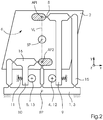
- FIG. 2 shows as an example one of the identical units of which the pressure bar 1 is composed.
- the first cone 12 abuts on the first lever arm 9 and the second cone 13 on the second lever arm 10 of the holder 3.
- the print head 2 is fastened to the holder 3.
- the holder 3 comprises longitudinal bars 15 and transverse bars 16.
- the bars 15, 16 and lever arms 9, 10 are connected to each other via elastic joints (bending joints, spring joints) 8 and together form a frame.
- the elastic joints 8 are tapers in which a bend takes place when the lever arms 9, 10 are pivoted in the common plane of the coordinate axes x, y or parallel to the nozzle surface 6 by the adjusting devices 4, 5.
- the elastic joints 8 have imaginary pivot axes which are parallel with the axes of rotation of the screws 7.
- each lever arm 9, 10 engages on the one side of the respective cone 12, 13 and on the other side to a return spring 11 which presses the lever arm 9, 10 against the cone 12, 13.
- a return spring 11 which presses the lever arm 9, 10 against the cone 12, 13.
- the center of gravity SP of the nozzle surface 6 lies in the center.
- FIG. 3 shows that the arranged between the lever arms 9, 10 adjusting devices 4, 5 press the lever arms 9, 10 apart.
- the two screws 7 are preferably screwed in at the same time something.
- an adjustment of the respective cone 12, 13 takes place in the direction parallel to the coordinate axis z - with respect to the axis of rotation of the screw 7 axially - and increases the effective diameter with which the cone 12, 13 presses on the lever arm 9, 10.
- the holder 3 deforms elastically such that the connection points AP1, AP2 change their position relative to a fixed point FP of the holder 3.
- Both attachment points AP1, AP2 are pivoted clockwise about the center of gravity SP, when the second lever arm 10 in the clockwise direction and the first lever arm 9 are pivoted counterclockwise.
- the movement of the attachment points AP1, AP2 relative to the fixed point FP results in a pivotal movement of the print head 2 about an imaginary axis of rotation RA which runs parallel to the coordinate axis z and through the center of gravity SP.
- the first connection point AP1 is shifted to the right and the second connection point AP2 to the left, ie, opposite to the first connection point AP1, to move the print head 2 about the axis of rotation RA to swing.
- the center of gravity SP does not change its position relative to the fixed point FP during the pivotal movement of the print head 2.
- the risk of a collision with adjacent print heads 2 is reduced.
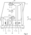
- FIG. 4 shows that the lever arms 9, 10 are compressed by the return springs 11.
- the one screw 7 unscrewed something and preferably at the same time the other screw 7 screwed something.
- the effective diameter increases, with which the second cone 13 presses on the second lever arm 10, so that it is also pivoted against the action of its associated return spring 11 in a clockwise direction.
- the holder 3 elastically deformed such that not only the connection points AP1, AP2, but also the center of gravity SP changes its position relative to the fixed point FP.
- the attachment points AP1, AP2 are both - so in the same direction - in with the coordinate axis x parallel direction with respect FIG. 4 moved to the left.
- the print head 2 and the center of gravity SP are also displaced to the left along an imaginary axis of translation TA relative to the fixed point FP.
- the translation axis TA is parallel to the coordinate axis x.
- the distance between the first attachment point AP1 and the center of gravity SP may be different than the distance between the second attachment point AP2 and the center of gravity SP.
Landscapes
- Ink Jet (AREA)
- Common Mechanisms (AREA)
Abstract
Description
- Vorliegende Erfindung betrifft einen Druckbalken für Inkjet, der Druckköpfe in einer Reihe, Halter, die jeweils einen Druckkopf halten, und Justiereinrichtungen zum Justieren der Druckköpfe zueinander umfasst.
- In
DE 11 2015 002 942 T5 ist ein sogenannter Zeilentyp-Tintenstrahlkopf beschrieben, der durch Verbinden mehrerer Kopfmodule miteinander entlang der x-Richtung gebildet ist. Es ist ein Aufzeichnungskopf-Einstellsystem vorhanden, mit dem die Winkelabweichung der Drehrichtung innerhalb der Ebene parallel zu der Aufzeichnungsfläche des Aufzeichnungskopfs eingestellt werden kann.
Ungünstig daran ist, dass bei der Justage eines Kopfmoduls dessen Düsenplatte mit der Düsenplatte eines benachbarten Kopfmoduls kollidieren kann. Die Düsenplatten sind sehr empfindlich und können bereits durch schwache Kollisionen beschädigt werden. - Aufgabe der Erfindung ist, einen Druckbalken zu schaffen, bei dem die Justage der Druckköpfe ohne Gefahr von Kollisionen möglich ist.
- Die Aufgabe wird gelöst durch einen Druckbalken für Inkjet, umfassend Druckköpfe in einer Reihe, Halter, die jeweils einen Druckkopf halten, und Justiereinrichtungen zum Justieren der Druckköpfe zueinander, wobei jeder Druckkopf eine Düsenfläche mit einem geometrischen Schwerpunkt aufweist, und der Druckbalken dadurch gekennzeichnet ist, dass jeder Druckkopf an seinem Halter in zwei Anbindungspunkten angebunden ist, die relativ zu einem Fixpunkt des Halters verstellbar sind, wobei eine imaginäre, gerade Verbindungslinie die Anbindungspunkte miteinander verbindet, und dass die Verbindungslinie durch den Schwerpunkt der Düsenfläche verläuft.
- Unter dem Schwerpunkt der Düsenfläche wird im Zusammenhang mit vorliegender Erfindung nicht nur der ideale Schwerpunkt verstanden, sondern auch ein Punkt, der innerhalb eines imaginären, kreisförmigen Toleranzbereiches liegt, dessen Kreismittelpunkt der ideale Schwerpunkt ist, wobei die Größe der Fläche des Toleranzbereiches höchstens 20%, insbesondere höchstens 10% und vorzugsweise höchstens 5% der Größe der gesamten Düsenfläche beträgt.
- Vorteil des erfindungsgemäßen Druckbalkens ist, dass bei der Justage des jeweiligen Druckkopfs dessen Rotation um den Schwerpunkt der Düsenfläche möglich ist, wodurch die Gefahr einer Kollision weitgehend gebannt ist.
- Es sind verschiedene Weiterbildungen möglich:
Pro Druckkopf können eine erste Justiereinrichtung und eine zweite Justiereinrichtung am Halter anliegen, so dass eine zueinander gegensinnige Verstellung der beiden Justiereinrichtungen eine Verstellung des Druckkopfs in einem ersten Freiheitsgrad und eine zueinander gleichsinnige Verstellung der beiden Justiereinrichtungen eine Verstellung des Druckkopfs in einem zweiten Freiheitsgrad bewirkt.
Der erste Freiheitsgrad kann durch eine Translationsachse und der zweite Freiheitsgrad eine Rotationsachse bestimmt sein.
Die Rotationsachse kann orthogonal zur Düsenfläche durch deren Schwerpunkt verlaufen. Die Justiereinrichtungen können jeweils einen Konus aufweisen.
Die Konen können an Schrauben ausgebildet sein.
Die Halter können jeweils als Rahmen mit Elastikgelenken und Hebelarmen ausgebildet sein.
Die Justiereinrichtungen können an den Hebelarmen anliegen.
Die Hebelarme können durch Rückstellfedern belastet sein, welche die Hebelarme gegen die Justiereinrichtungen drücken.
Die Verstellungen der beiden Justiereinrichtungen können lineare, insbesondere rotationsaxiale, Verschiebungen sein. - Weiterbildungen ergeben sich auch aus der nachfolgenden Beschreibung eines Ausführungsbeispiels und der zugehörigen Zeichnung, in welcher zeigt:
- Figur 1:
- das Schema eines Druckbalkens mit mehreren Einheiten,
- Figur 2:
- die Detaildarstellung einer Einheit, welche einen Druckkopf nebst zugehörigen Justiereinrichtungen und einen Halter umfasst,
- Figur 3:
- die Einheit bei einer rotativen Justage des Druckkopfs durch die Justiereinrichtungen und
- Figur 4:
- die Einheit bei einer translativen Justage des Druckkopfs durch die Justiereinrichtungen.
-
Figur 1 zeigt als Bestandteil einer Digitaldruckmaschine einen Druckbalken 1 für seitenbreiten Inkjetdruck auf Bogen oder eine Bahn. Der Bedruckstoff wird in Richtung der Koordinatenachse y unter dem Druckbalken 1 daran vorbeitransportiert. Entlang des Druckbalkens 1 sind Halter 3 angeordnet, die jeweils einen Druckkopf 2 mit einer Düsenfläche 6 tragen. - Jeder Halter 3 hat eine erste Justiereinrichtung 4 und eine zweite Justiereinrichtung 5 zum Drehen des Druckkopfs 2 um die Koordinatenachse z und Verschieben des Druckkopfs 2 entlang der Koordinatenachse x. Mit den Justiereinrichtungen 4, 5 wird der Druckkopf 2 relativ zu seinen benachbarten Druckköpfen 2 eingestellt. Jede Justiereinrichtung 4, 5 umfasst eine Schraube 7 mit zugehörigem Antriebselement 14 zum Drehen der Schraube 7. Das Antriebselement 14 kann ein Schraubenkopf für einen Steckschlüssel, ein Knauf als Handgriff oder vorzugsweise ein Elektromotor sein. Die beiden Schrauben 7 des jeweiligen Halters 3 sind miteinander parallel orientiert. Jede Schraube 7 hat einen Konus 12, 13 als Schubkeil, der beim Einschrauben der Schraube 7 einen Hebelarm 9, 10 wegdrückt, der an dem Schubkeil anliegt.
-
Figur 2 zeigt als Beispiel eine der baugleichen Einheiten, aus denen der Druckbalken 1 zusammengesetzt ist. Der erste Konus 12 liegt an dem ersten Hebelarm 9 an und der zweite Konus 13 an dem zweiten Hebelarm 10 des Halters 3. In einem ersten Anbindungspunkt AP1 und zweiten Anbindungspunkt AP2 ist der Druckkopf 2 an dem Halter 3 befestigt. - Der Halter 3 umfasst Längsstäbe 15 und Querstäbe 16. Die Stäbe 15, 16 und Hebelarme 9, 10 sind über Elastikgelenke (Biegegelenke, Federgelenke) 8 miteinander verbunden und bilden zusammen einen Rahmen. Die Elastikgelenke 8 sind Verjüngungen, in denen eine Biegung erfolgt, wenn die Hebelarme 9, 10 in der gemeinsamen Ebene der Koordinatenachsen x, y bzw. parallel zur Düsenfläche 6 durch die Justiereinrichtungen 4, 5 geschwenkt werden. Die Elastikgelenke 8 haben imaginäre Schwenkachsen, die parallel mit den Rotationsachsen der Schrauben 7 sind.
- Am freien Ende jedes Hebelarms 9, 10 greift auf der einen Seite der jeweilige Konus 12, 13 und auf der anderen Seite eine Rückstellfeder 11 an, die den Hebelarm 9, 10 gegen den Konus 12, 13 drückt. Auf einer imaginären, geraden Verbindungslinie VL vom ersten Anbindungspunkt AP1 zum zweiten Anbindungspunkt AP2 liegt in der Mitte der geometrische Schwerpunkt SP der Düsenfläche 6.
-
Figur 3 zeigt, dass die zwischen den Hebelarmen 9, 10 angeordneten Justiereinrichtungen 4, 5 die Hebelarme 9, 10 auseinander drücken. Hierzu werden die beiden Schrauben 7 vorzugsweise gleichzeitig etwas eingeschraubt. Dabei erfolgt eine Verstellung des jeweiligen Konus 12, 13 in mit der Koordinatenachse z paralleler Richtung - bezüglich der Rotationsachse der Schraube 7 axial - und vergrößert sich der Wirkdurchmesser, mit dem der Konus 12, 13 auf den Hebelarm 9, 10 drückt. Beim Drücken der Hebelarme 9, 10 voneinander weg verformt sich der Halter 3 elastisch derart, dass die Anbindungspunkte AP1, AP2 ihre Position relativ zu einem Fixpunkt FP des Halters 3 ändern. Beide Anbindungspunkte AP1, AP2 werden im Uhrzeigersinn um den Schwerpunkt SP geschwenkt, wenn der zweite Hebelarm 10 im Uhrzeigersinn und der erste Hebelarm 9 entgegen dem Uhrzeigersinn geschwenkt werden. - Aus der Bewegung der Anbindungspunkte AP1, AP2 relativ zu dem Fixpunkt FP resultiert eine Schwenkbewegung des Druckkopfs 2 um eine imaginäre Rotationsachse RA, die mit der Koordinatenachse z parallel und durch den Schwerpunkt SP verläuft. Näherungsweise in mit der Koordinatenachse x paralleler Richtung wird der erste Anbindungspunkt AP1 nach rechts und der zweite Anbindungspunkt AP2 nach links - also gegensinnig zum ersten Anbindungspunkt AP1 - verschoben, um den Druckkopf 2 um die Rotationsachse RA zu schwenken. Der Schwerpunkt SP ändert seine Position relativ zum Fixpunkt FP bei der Schwenkbewegung des Druckkopfs 2 nicht. Bei der Schwenkbewegung oder Rotation des Druckkopfs 2 um den Schwerpunkt SP ist die Gefahr einer Kollision mit benachbarten Druckköpfen 2 verringert.
-
Figur 4 zeigt, dass die Hebelarme 9, 10 von den Rückstellfedern 11 zusammengedrückt werden. Um dies zu ermöglichen, wird mit Bezug auf die Neutralstellung inFigur 2 die eine Schraube 7 etwas herausgeschraubt und vorzugsweise gleichzeitig die andere Schraube 7 etwas eingeschraubt. Dadurch verringert sich der Wirkdurchmesser, mit dem der erste Konus 12 am ersten Hebelarm 9 anliegt, so dass die an ihm angreifende Rückstellfeder 11 den ersten Hebelarm 9 im Uhrzeigersinn schwenken kann. Außerdem vergrößert sich der Wirkdurchmesser, mit dem der zweite Konus 13 auf den zweiten Hebelarm 10 drückt, so dass dieser gegen die Wirkung der ihm zugeordneten Rückstellfeder 11 ebenfalls im Uhrzeigersinn geschwenkt wird. Bei diesem gleichsinnigen Schwenken der Hebelarme 9, 10 verformt sich der Halter 3 elastisch derart, dass nicht nur die Anbindungspunkte AP1, AP2, sondern auch der Schwerpunkt SP seine Position relativ zu dem Fixpunkt FP ändert. - Die Anbindungspunkte AP1, AP2 werden beide - also miteinander gleichsinnig - in mit der Koordinatenachse x paralleler Richtung bezüglich
Figur 4 nach links verschoben. Dadurch wird der Druckkopf 2 und Schwerpunkt SP entlang einer imaginären Translationsachse TA relativ zum Fixpunkt FP ebenfalls nach links verschoben. Die Translationsachse TA ist parallel mit der Koordinatenachse x. - Verschiedene Modifikationen sind möglich:
Im zuvor beschriebenen Beispiel wird davon ausgegangen, dass sich die Konen 12, 13 jeweils zur Spitze ihrer Schraube 7 hin verjüngen.
Es ist aber auch denkbar, dass sich die Konen 12, 13 zu den Spitzen hin verbreitern. In diesem Fall müssten beide Schrauben 7 etwas herausgeschraubt werden, um die Hebelarme 9, 10 zum Schwenken des Druckkopfs 2 (Figur 3 ) auseinander zu drücken.
Bei den zuvor genannten Varianten verjüngen oder verbreitern sich beide Konen 12, 13 zu den Schraubenspitzen hin, also gleichsinnig.
Ebenso ist aber auch eine Variante denkbar, bei der die Durchmesserveränderung der beiden Konen 12, 13 gegensinnig verläuft. Beispielsweise verjüngt sich der erste Konus 12 zur Spitze der Schraube 7 hin und verbreitert sich der zweite Konus 13 zur Schraubenspitze hin. Hierbei müsste der erste Konus 12 etwas eingeschraubt und der zweite Konus 13 etwas ausgeschraubt werden, um die Hebelarme 9, 10 zwecks Rotation des Druckkopfs 2 um den Schwenkpunkt SP zu verstellen. - Auch ist eine alternative Ausbildung der Justiereinrichtungen 4, 5 denkbar, wobei zum Beispiel die Schrauben 7 mit den Konen 12, 13 durch pyramidenförmige Schubkeile mit Flachseiten ersetzt werden, an denen die Hebelarme 9, 10 anliegen.
- Letztlich kann bei entsprechender Dimensionierung der Stäbe 15, 16 und Hebelarme 10, 11 der Abstand zwischen dem ersten Anbindungspunkt AP1 und dem Schwerpunkt SP ein anderer als der Abstand zwischen dem zweiten Anbindungspunkt AP2 und dem Schwerpunkt SP sein. Durch eine dementsprechende Ausbildung des Halters 3 kann trotzdem sichergestellt werden, dass die beiden Anbindungspunkte AP1, AP2 ihre diametrale Relativlage beim Schwenken um den Schwenkpunkt SP beibehalten. Entscheidend ist, dass auch hierbei die Düsenfläche 6 um ihren geometrischen Schwerpunkt SP geschwenkt wird.
-
- 1
- Druckbalken
- 2
- Druckkopf
- 3
- Halter
- 4
- erste Justiereinrichtung
- 5
- zweite Justiereinrichtung
- 6
- Düsenfläche
- 7
- Schraube
- 8
- Elastikgelenk
- 9
- erster Hebelarm
- 10
- zweiter Hebelarm
- 11
- Rückstellfeder
- 12
- erster Konus
- 13
- zweiter Konus
- 14
- Antriebselement
- 15
- Längsstab
- 16
- Querstab
- AP1
- erster Anbindungspunkt
- AP2
- zweiter Anbindungspunkt
- FP
- Fixpunkt
- RA
- Rotationsachse
- SP
- Schwerpunkt
- TA
- Translationsachse
- VL
- Verbindungslinie
- x
- Koordinatenachse
- y
- Koordinatenachse
- z
- Koordinatenachse
Claims (10)
- Druckbalken (1) für Inkjet, umfassend
Druckköpfe (2) in einer Reihe,
Halter (3), die jeweils einen Druckkopf (2) halten, und
Justiereinrichtungen (4, 5) zum Justieren der Druckköpfe (2) zueinander, wobei jeder Druckkopf (2) eine Düsenfläche (6) mit einem geometrischen Schwerpunkt (SP) aufweist,
dadurch gekennzeichnet,
dass jeder Druckkopf (2) an seinem Halter (3) in zwei Anbindungspunkten (AP1, AP2) angebunden ist, die relativ zu einem Fixpunkt (FP) des Halters (3) verstellbar sind,
wobei eine imaginäre, gerade Verbindungslinie (VL) die Anbindungspunkte (AP1, AP2) miteinander verbindet, und
dass die Verbindungslinie (VL) durch den Schwerpunkt (SP) der Düsenfläche (6) verläuft. - Druckbalken nach Anspruch 1,
dadurch gekennzeichnet,
dass pro Druckkopf (2) eine erste Justiereinrichtung (4) und eine zweite Justiereinrichtung (5) am Halter (3) anliegen, so dass eine zueinander gegensinnige Verstellung der beiden Justiereinrichtungen (4, 5) eine Verstellung des Druckkopfs (3) in einen ersten Freiheitsgrad und eine zueinander gleichsinnige Verstellung der beiden Justiereinrichtungen (4, 5) eine Verstellung des Druckkopfs (3) in einen zweiten Freiheitsgrad bewirkt. - Druckbalken nach Anspruch 2,
dadurch gekennzeichnet,
dass der erste Freiheitsgrad durch eine Translationsachse (TA) und der zweite Freiheitsgrad eine Rotationsachse (RA) bestimmt ist. - Druckbalken nach Anspruch 3,
dadurch gekennzeichnet,
dass die Rotationsachse (RA) orthogonal zur Düsenfläche (6) durch deren Schwerpunkt (SP) verläuft. - Druckbalken nach einem der Ansprüche 1 bis 4,
dadurch gekennzeichnet,
dass die Justiereinrichtungen (4, 5) jeweils einen Konus (12, 13) aufweisen. - Druckbalken nach Anspruch 5,
dadurch gekennzeichnet,
dass die Konen (12, 13) an Schrauben (7) ausgebildet sind. - Druckbalken nach einem der Ansprüche 1 bis 6,
dadurch gekennzeichnet,
dass die Halter (3) jeweils als Rahmen mit Elastikgelenken (8) und Hebelarmen (9, 19) ausgebildet sind. - Druckbalken nach Anspruch 7,
dadurch gekennzeichnet,
dass die Justiereinrichtungen (4, 5) an den Hebelarmen (9, 10) anliegen. - Druckbalken nach Anspruch 7 oder 8,
dadurch gekennzeichnet,
dass die Hebelarme (9, 10) durch Rückstellfedern (11) belastet sind, welche die Hebelarme (9, 10) gegen die Justiereinrichtungen (4, 5) drücken. - Druckbalken nach einem der Ansprüche 2 bis 4,
dadurch gekennzeichnet,
dass die Verstellungen der beiden Justiereinrichtungen (4, 5) lineare Verschiebungen sind.
Priority Applications (1)
| Application Number | Priority Date | Filing Date | Title |
|---|---|---|---|
| EP18162185.5A EP3539791B1 (de) | 2018-03-16 | 2018-03-16 | Druckbalken für inkjet |
Applications Claiming Priority (1)
| Application Number | Priority Date | Filing Date | Title |
|---|---|---|---|
| EP18162185.5A EP3539791B1 (de) | 2018-03-16 | 2018-03-16 | Druckbalken für inkjet |
Publications (2)
| Publication Number | Publication Date |
|---|---|
| EP3539791A1 true EP3539791A1 (de) | 2019-09-18 |
| EP3539791B1 EP3539791B1 (de) | 2023-01-18 |
Family
ID=61691300
Family Applications (1)
| Application Number | Title | Priority Date | Filing Date |
|---|---|---|---|
| EP18162185.5A Active EP3539791B1 (de) | 2018-03-16 | 2018-03-16 | Druckbalken für inkjet |
Country Status (1)
| Country | Link |
|---|---|
| EP (1) | EP3539791B1 (de) |
Cited By (1)
| Publication number | Priority date | Publication date | Assignee | Title |
|---|---|---|---|---|
| EP4169725A1 (de) * | 2021-10-25 | 2023-04-26 | SII Printek Inc. | Flüssigkeitsstrahlkopf und flüssigkeitsstrahlaufzeichnungsvorrichtung |
Citations (4)
| Publication number | Priority date | Publication date | Assignee | Title |
|---|---|---|---|---|
| NL2008063C2 (en) * | 2012-01-02 | 2013-07-03 | Mutracx B V | Inkjet printing system. |
| US20140160201A1 (en) * | 2012-03-09 | 2014-06-12 | Dilli | Head alignment assembly |
| US20160279982A1 (en) * | 2015-03-27 | 2016-09-29 | Fuji Xerox Co., Ltd. | Droplets ejecting apparatus |
| DE112015002942T5 (de) | 2014-06-23 | 2017-03-02 | Fujifilm Corporation | Aufzeichnungskopf, Aufzeichnungskopf-Einstellsystem und Aufzeichnungskopf-Einstellverfahren |
Family Cites Families (1)
| Publication number | Priority date | Publication date | Assignee | Title |
|---|---|---|---|---|
| JP6639318B2 (ja) * | 2016-04-21 | 2020-02-05 | エスアイアイ・プリンテック株式会社 | キャリッジおよび液体噴射記録装置 |
-
2018
- 2018-03-16 EP EP18162185.5A patent/EP3539791B1/de active Active
Patent Citations (4)
| Publication number | Priority date | Publication date | Assignee | Title |
|---|---|---|---|---|
| NL2008063C2 (en) * | 2012-01-02 | 2013-07-03 | Mutracx B V | Inkjet printing system. |
| US20140160201A1 (en) * | 2012-03-09 | 2014-06-12 | Dilli | Head alignment assembly |
| DE112015002942T5 (de) | 2014-06-23 | 2017-03-02 | Fujifilm Corporation | Aufzeichnungskopf, Aufzeichnungskopf-Einstellsystem und Aufzeichnungskopf-Einstellverfahren |
| US20160279982A1 (en) * | 2015-03-27 | 2016-09-29 | Fuji Xerox Co., Ltd. | Droplets ejecting apparatus |
Cited By (3)
| Publication number | Priority date | Publication date | Assignee | Title |
|---|---|---|---|---|
| EP4169725A1 (de) * | 2021-10-25 | 2023-04-26 | SII Printek Inc. | Flüssigkeitsstrahlkopf und flüssigkeitsstrahlaufzeichnungsvorrichtung |
| CN116021888A (zh) * | 2021-10-25 | 2023-04-28 | 精工电子打印科技有限公司 | 液体喷射头和液体喷射记录装置 |
| US11964484B2 (en) | 2021-10-25 | 2024-04-23 | Sii Printek Inc. | Liquid jet head and liquid jet recording device |
Also Published As
| Publication number | Publication date |
|---|---|
| EP3539791B1 (de) | 2023-01-18 |
Similar Documents
| Publication | Publication Date | Title |
|---|---|---|
| DE69601121T2 (de) | Schnellspannvorrichtung für wenigstens ein Werkzeug einer Werkzeugmaschine | |
| DE1966879C3 (de) | Einrichtung zum Festklemmen einer Aufspannplatte an einem Preßschlitten | |
| DE102004041472B4 (de) | Vorrichtung zum Transportieren eines Bedruckstoffbogens | |
| EP3825029B1 (de) | Einweiservorrichtung | |
| DE2263068C3 (de) | Kompakteinheit zum elektrischen Punktschweißen | |
| DE102007040278B4 (de) | Schneidvorrichtung zum Schneiden von aus Blättern gebildeten Stapeln | |
| DE2255275B1 (de) | Vorrichtung zum Längsschneiden von Materialbahnen, insbesondere Papierbahn nen | |
| EP3539791B1 (de) | Druckbalken für inkjet | |
| EP1916043B1 (de) | Runde- oder Biegemaschine | |
| EP1611287B1 (de) | Vorrichtung zur montage von schienenklemmen | |
| DE3104667A1 (de) | Ladeeinrichtung fuer metallrohlinge | |
| EP2210680B1 (de) | Biegepresse mit einem Antriebsbalken und elastisch gekuppelten Biegebalken | |
| DE102014103827A1 (de) | Antriebsvorrichtung zum Antrieb eines Werkzeugschiebers in einer Falzanlage | |
| DE10102488B4 (de) | Vorrichtung zur Höheneinstellung einer Mehrzahl von Werkzeughaltern für eine Abkantpresse | |
| EP2769816A1 (de) | Fräsaggregat | |
| DE60206589T2 (de) | Ausrichtvorrichtung und Ausrichtverfahren für Tintenstrahldrucker | |
| DE69005575T2 (de) | Befestigung eines Werkzeugs zum Ausstossen oder Abtrennen von Teilen oder eines ähnlichen Werkzeugs. | |
| EP4178738B1 (de) | Biegevorrichtung mit durchbiegungsausgleich | |
| EP4501642B1 (de) | Verfahren und vorrichtung zur mehrstufigen zylinderaufnahme | |
| CH656834A5 (de) | Vorrichtung zum diagonalverstellen eines plattenzylinders einer druckmaschine. | |
| DE102022122828B3 (de) | Kontaktelement | |
| EP2641668A1 (de) | Blechbiegemaschine | |
| EP3441187A1 (de) | Werkstückhandhabungsausrüstung mit einer mehrzahl von werkstückträgern und mindestens einer trägereinstellstation | |
| EP1567342A1 (de) | Farbkammerrakel | |
| DE202023102660U1 (de) | Vorrichtung zum Zerlegen und zum Montieren eines Kreuzgelenks |
Legal Events
| Date | Code | Title | Description |
|---|---|---|---|
| PUAI | Public reference made under article 153(3) epc to a published international application that has entered the european phase |
Free format text: ORIGINAL CODE: 0009012 |
|
| STAA | Information on the status of an ep patent application or granted ep patent |
Free format text: STATUS: THE APPLICATION HAS BEEN PUBLISHED |
|
| AK | Designated contracting states |
Kind code of ref document: A1 Designated state(s): AL AT BE BG CH CY CZ DE DK EE ES FI FR GB GR HR HU IE IS IT LI LT LU LV MC MK MT NL NO PL PT RO RS SE SI SK SM TR |
|
| AX | Request for extension of the european patent |
Extension state: BA ME |
|
| STAA | Information on the status of an ep patent application or granted ep patent |
Free format text: STATUS: REQUEST FOR EXAMINATION WAS MADE |
|
| 17P | Request for examination filed |
Effective date: 20200318 |
|
| RBV | Designated contracting states (corrected) |
Designated state(s): AL AT BE BG CH CY CZ DE DK EE ES FI FR GB GR HR HU IE IS IT LI LT LU LV MC MK MT NL NO PL PT RO RS SE SI SK SM TR |
|
| STAA | Information on the status of an ep patent application or granted ep patent |
Free format text: STATUS: EXAMINATION IS IN PROGRESS |
|
| 17Q | First examination report despatched |
Effective date: 20220125 |
|
| GRAP | Despatch of communication of intention to grant a patent |
Free format text: ORIGINAL CODE: EPIDOSNIGR1 |
|
| STAA | Information on the status of an ep patent application or granted ep patent |
Free format text: STATUS: GRANT OF PATENT IS INTENDED |
|
| INTG | Intention to grant announced |
Effective date: 20221004 |
|
| GRAS | Grant fee paid |
Free format text: ORIGINAL CODE: EPIDOSNIGR3 |
|
| GRAA | (expected) grant |
Free format text: ORIGINAL CODE: 0009210 |
|
| STAA | Information on the status of an ep patent application or granted ep patent |
Free format text: STATUS: THE PATENT HAS BEEN GRANTED |
|
| AK | Designated contracting states |
Kind code of ref document: B1 Designated state(s): AL AT BE BG CH CY CZ DE DK EE ES FI FR GB GR HR HU IE IS IT LI LT LU LV MC MK MT NL NO PL PT RO RS SE SI SK SM TR |
|
| REG | Reference to a national code |
Ref country code: GB Ref legal event code: FG4D Free format text: NOT ENGLISH |
|
| REG | Reference to a national code |
Ref country code: CH Ref legal event code: EP |
|
| REG | Reference to a national code |
Ref country code: AT Ref legal event code: REF Ref document number: 1544471 Country of ref document: AT Kind code of ref document: T Effective date: 20230215 Ref country code: IE Ref legal event code: FG4D Free format text: LANGUAGE OF EP DOCUMENT: GERMAN |
|
| REG | Reference to a national code |
Ref country code: DE Ref legal event code: R096 Ref document number: 502018011444 Country of ref document: DE |
|
| REG | Reference to a national code |
Ref country code: LT Ref legal event code: MG9D |
|
| REG | Reference to a national code |
Ref country code: NL Ref legal event code: MP Effective date: 20230118 |
|
| P01 | Opt-out of the competence of the unified patent court (upc) registered |
Effective date: 20230502 |
|
| PG25 | Lapsed in a contracting state [announced via postgrant information from national office to epo] |
Ref country code: NL Free format text: LAPSE BECAUSE OF FAILURE TO SUBMIT A TRANSLATION OF THE DESCRIPTION OR TO PAY THE FEE WITHIN THE PRESCRIBED TIME-LIMIT Effective date: 20230118 |
|
| PG25 | Lapsed in a contracting state [announced via postgrant information from national office to epo] |
Ref country code: RS Free format text: LAPSE BECAUSE OF FAILURE TO SUBMIT A TRANSLATION OF THE DESCRIPTION OR TO PAY THE FEE WITHIN THE PRESCRIBED TIME-LIMIT Effective date: 20230118 Ref country code: PT Free format text: LAPSE BECAUSE OF FAILURE TO SUBMIT A TRANSLATION OF THE DESCRIPTION OR TO PAY THE FEE WITHIN THE PRESCRIBED TIME-LIMIT Effective date: 20230518 Ref country code: NO Free format text: LAPSE BECAUSE OF FAILURE TO SUBMIT A TRANSLATION OF THE DESCRIPTION OR TO PAY THE FEE WITHIN THE PRESCRIBED TIME-LIMIT Effective date: 20230418 Ref country code: LV Free format text: LAPSE BECAUSE OF FAILURE TO SUBMIT A TRANSLATION OF THE DESCRIPTION OR TO PAY THE FEE WITHIN THE PRESCRIBED TIME-LIMIT Effective date: 20230118 Ref country code: LT Free format text: LAPSE BECAUSE OF FAILURE TO SUBMIT A TRANSLATION OF THE DESCRIPTION OR TO PAY THE FEE WITHIN THE PRESCRIBED TIME-LIMIT Effective date: 20230118 Ref country code: HR Free format text: LAPSE BECAUSE OF FAILURE TO SUBMIT A TRANSLATION OF THE DESCRIPTION OR TO PAY THE FEE WITHIN THE PRESCRIBED TIME-LIMIT Effective date: 20230118 Ref country code: ES Free format text: LAPSE BECAUSE OF FAILURE TO SUBMIT A TRANSLATION OF THE DESCRIPTION OR TO PAY THE FEE WITHIN THE PRESCRIBED TIME-LIMIT Effective date: 20230118 |
|
| PG25 | Lapsed in a contracting state [announced via postgrant information from national office to epo] |
Ref country code: SE Free format text: LAPSE BECAUSE OF FAILURE TO SUBMIT A TRANSLATION OF THE DESCRIPTION OR TO PAY THE FEE WITHIN THE PRESCRIBED TIME-LIMIT Effective date: 20230118 Ref country code: PL Free format text: LAPSE BECAUSE OF FAILURE TO SUBMIT A TRANSLATION OF THE DESCRIPTION OR TO PAY THE FEE WITHIN THE PRESCRIBED TIME-LIMIT Effective date: 20230118 Ref country code: IS Free format text: LAPSE BECAUSE OF FAILURE TO SUBMIT A TRANSLATION OF THE DESCRIPTION OR TO PAY THE FEE WITHIN THE PRESCRIBED TIME-LIMIT Effective date: 20230518 Ref country code: GR Free format text: LAPSE BECAUSE OF FAILURE TO SUBMIT A TRANSLATION OF THE DESCRIPTION OR TO PAY THE FEE WITHIN THE PRESCRIBED TIME-LIMIT Effective date: 20230419 Ref country code: FI Free format text: LAPSE BECAUSE OF FAILURE TO SUBMIT A TRANSLATION OF THE DESCRIPTION OR TO PAY THE FEE WITHIN THE PRESCRIBED TIME-LIMIT Effective date: 20230118 |
|
| REG | Reference to a national code |
Ref country code: DE Ref legal event code: R097 Ref document number: 502018011444 Country of ref document: DE |
|
| PG25 | Lapsed in a contracting state [announced via postgrant information from national office to epo] |
Ref country code: SM Free format text: LAPSE BECAUSE OF FAILURE TO SUBMIT A TRANSLATION OF THE DESCRIPTION OR TO PAY THE FEE WITHIN THE PRESCRIBED TIME-LIMIT Effective date: 20230118 Ref country code: RO Free format text: LAPSE BECAUSE OF FAILURE TO SUBMIT A TRANSLATION OF THE DESCRIPTION OR TO PAY THE FEE WITHIN THE PRESCRIBED TIME-LIMIT Effective date: 20230118 Ref country code: MC Free format text: LAPSE BECAUSE OF FAILURE TO SUBMIT A TRANSLATION OF THE DESCRIPTION OR TO PAY THE FEE WITHIN THE PRESCRIBED TIME-LIMIT Effective date: 20230118 Ref country code: EE Free format text: LAPSE BECAUSE OF FAILURE TO SUBMIT A TRANSLATION OF THE DESCRIPTION OR TO PAY THE FEE WITHIN THE PRESCRIBED TIME-LIMIT Effective date: 20230118 Ref country code: DK Free format text: LAPSE BECAUSE OF FAILURE TO SUBMIT A TRANSLATION OF THE DESCRIPTION OR TO PAY THE FEE WITHIN THE PRESCRIBED TIME-LIMIT Effective date: 20230118 Ref country code: CZ Free format text: LAPSE BECAUSE OF FAILURE TO SUBMIT A TRANSLATION OF THE DESCRIPTION OR TO PAY THE FEE WITHIN THE PRESCRIBED TIME-LIMIT Effective date: 20230118 |
|
| REG | Reference to a national code |
Ref country code: CH Ref legal event code: PL |
|
| PLBE | No opposition filed within time limit |
Free format text: ORIGINAL CODE: 0009261 |
|
| STAA | Information on the status of an ep patent application or granted ep patent |
Free format text: STATUS: NO OPPOSITION FILED WITHIN TIME LIMIT |
|
| PG25 | Lapsed in a contracting state [announced via postgrant information from national office to epo] |
Ref country code: SK Free format text: LAPSE BECAUSE OF FAILURE TO SUBMIT A TRANSLATION OF THE DESCRIPTION OR TO PAY THE FEE WITHIN THE PRESCRIBED TIME-LIMIT Effective date: 20230118 |
|
| REG | Reference to a national code |
Ref country code: BE Ref legal event code: MM Effective date: 20230331 |
|
| 26N | No opposition filed |
Effective date: 20231019 |
|
| GBPC | Gb: european patent ceased through non-payment of renewal fee |
Effective date: 20230418 |
|
| PG25 | Lapsed in a contracting state [announced via postgrant information from national office to epo] |
Ref country code: LU Free format text: LAPSE BECAUSE OF NON-PAYMENT OF DUE FEES Effective date: 20230316 |
|
| REG | Reference to a national code |
Ref country code: IE Ref legal event code: MM4A |
|
| PG25 | Lapsed in a contracting state [announced via postgrant information from national office to epo] |
Ref country code: GB Free format text: LAPSE BECAUSE OF NON-PAYMENT OF DUE FEES Effective date: 20230418 |
|
| PG25 | Lapsed in a contracting state [announced via postgrant information from national office to epo] |
Ref country code: SI Free format text: LAPSE BECAUSE OF FAILURE TO SUBMIT A TRANSLATION OF THE DESCRIPTION OR TO PAY THE FEE WITHIN THE PRESCRIBED TIME-LIMIT Effective date: 20230118 Ref country code: LI Free format text: LAPSE BECAUSE OF NON-PAYMENT OF DUE FEES Effective date: 20230331 Ref country code: IE Free format text: LAPSE BECAUSE OF NON-PAYMENT OF DUE FEES Effective date: 20230316 Ref country code: GB Free format text: LAPSE BECAUSE OF NON-PAYMENT OF DUE FEES Effective date: 20230418 Ref country code: FR Free format text: LAPSE BECAUSE OF NON-PAYMENT OF DUE FEES Effective date: 20230318 Ref country code: CH Free format text: LAPSE BECAUSE OF NON-PAYMENT OF DUE FEES Effective date: 20230331 |
|
| PG25 | Lapsed in a contracting state [announced via postgrant information from national office to epo] |
Ref country code: BE Free format text: LAPSE BECAUSE OF NON-PAYMENT OF DUE FEES Effective date: 20230331 |
|
| REG | Reference to a national code |
Ref country code: AT Ref legal event code: MM01 Ref document number: 1544471 Country of ref document: AT Kind code of ref document: T Effective date: 20230316 |
|
| PG25 | Lapsed in a contracting state [announced via postgrant information from national office to epo] |
Ref country code: IT Free format text: LAPSE BECAUSE OF FAILURE TO SUBMIT A TRANSLATION OF THE DESCRIPTION OR TO PAY THE FEE WITHIN THE PRESCRIBED TIME-LIMIT Effective date: 20230118 |
|
| PG25 | Lapsed in a contracting state [announced via postgrant information from national office to epo] |
Ref country code: AT Free format text: LAPSE BECAUSE OF NON-PAYMENT OF DUE FEES Effective date: 20230316 |
|
| PG25 | Lapsed in a contracting state [announced via postgrant information from national office to epo] |
Ref country code: AT Free format text: LAPSE BECAUSE OF NON-PAYMENT OF DUE FEES Effective date: 20230316 |
|
| PG25 | Lapsed in a contracting state [announced via postgrant information from national office to epo] |
Ref country code: BG Free format text: LAPSE BECAUSE OF FAILURE TO SUBMIT A TRANSLATION OF THE DESCRIPTION OR TO PAY THE FEE WITHIN THE PRESCRIBED TIME-LIMIT Effective date: 20230118 |
|
| PG25 | Lapsed in a contracting state [announced via postgrant information from national office to epo] |
Ref country code: BG Free format text: LAPSE BECAUSE OF FAILURE TO SUBMIT A TRANSLATION OF THE DESCRIPTION OR TO PAY THE FEE WITHIN THE PRESCRIBED TIME-LIMIT Effective date: 20230118 |
|
| PG25 | Lapsed in a contracting state [announced via postgrant information from national office to epo] |
Ref country code: CY Free format text: LAPSE BECAUSE OF FAILURE TO SUBMIT A TRANSLATION OF THE DESCRIPTION OR TO PAY THE FEE WITHIN THE PRESCRIBED TIME-LIMIT; INVALID AB INITIO Effective date: 20180316 |
|
| PG25 | Lapsed in a contracting state [announced via postgrant information from national office to epo] |
Ref country code: HU Free format text: LAPSE BECAUSE OF FAILURE TO SUBMIT A TRANSLATION OF THE DESCRIPTION OR TO PAY THE FEE WITHIN THE PRESCRIBED TIME-LIMIT; INVALID AB INITIO Effective date: 20180316 |
|
| PG25 | Lapsed in a contracting state [announced via postgrant information from national office to epo] |
Ref country code: TR Free format text: LAPSE BECAUSE OF FAILURE TO SUBMIT A TRANSLATION OF THE DESCRIPTION OR TO PAY THE FEE WITHIN THE PRESCRIBED TIME-LIMIT Effective date: 20230118 |
|
| PGFP | Annual fee paid to national office [announced via postgrant information from national office to epo] |
Ref country code: DE Payment date: 20260331 Year of fee payment: 9 |