EP3539751A1 - Herstellungsvorrichtung und herstellungsverfahren - Google Patents
Herstellungsvorrichtung und herstellungsverfahren Download PDFInfo
- Publication number
- EP3539751A1 EP3539751A1 EP19160163.2A EP19160163A EP3539751A1 EP 3539751 A1 EP3539751 A1 EP 3539751A1 EP 19160163 A EP19160163 A EP 19160163A EP 3539751 A1 EP3539751 A1 EP 3539751A1
- Authority
- EP
- European Patent Office
- Prior art keywords
- fabrication
- filament
- fabricating apparatus
- layer
- heating
- Prior art date
- Legal status (The legal status is an assumption and is not a legal conclusion. Google has not performed a legal analysis and makes no representation as to the accuracy of the status listed.)
- Withdrawn
Links
Images








Classifications
-
- B—PERFORMING OPERATIONS; TRANSPORTING
- B29—WORKING OF PLASTICS; WORKING OF SUBSTANCES IN A PLASTIC STATE IN GENERAL
- B29C—SHAPING OR JOINING OF PLASTICS; SHAPING OF MATERIAL IN A PLASTIC STATE, NOT OTHERWISE PROVIDED FOR; AFTER-TREATMENT OF THE SHAPED PRODUCTS, e.g. REPAIRING
- B29C64/00—Additive manufacturing, i.e. manufacturing of three-dimensional [3D] objects by additive deposition, additive agglomeration or additive layering, e.g. by 3D printing, stereolithography or selective laser sintering
- B29C64/10—Processes of additive manufacturing
- B29C64/106—Processes of additive manufacturing using only liquids or viscous materials, e.g. depositing a continuous bead of viscous material
- B29C64/118—Processes of additive manufacturing using only liquids or viscous materials, e.g. depositing a continuous bead of viscous material using filamentary material being melted, e.g. fused deposition modelling [FDM]
-
- B—PERFORMING OPERATIONS; TRANSPORTING
- B29—WORKING OF PLASTICS; WORKING OF SUBSTANCES IN A PLASTIC STATE IN GENERAL
- B29C—SHAPING OR JOINING OF PLASTICS; SHAPING OF MATERIAL IN A PLASTIC STATE, NOT OTHERWISE PROVIDED FOR; AFTER-TREATMENT OF THE SHAPED PRODUCTS, e.g. REPAIRING
- B29C64/00—Additive manufacturing, i.e. manufacturing of three-dimensional [3D] objects by additive deposition, additive agglomeration or additive layering, e.g. by 3D printing, stereolithography or selective laser sintering
- B29C64/40—Structures for supporting 3D objects during manufacture and intended to be sacrificed after completion thereof
-
- B—PERFORMING OPERATIONS; TRANSPORTING
- B33—ADDITIVE MANUFACTURING TECHNOLOGY
- B33Y—ADDITIVE MANUFACTURING, i.e. MANUFACTURING OF THREE-DIMENSIONAL [3D] OBJECTS BY ADDITIVE DEPOSITION, ADDITIVE AGGLOMERATION OR ADDITIVE LAYERING, e.g. BY 3D PRINTING, STEREOLITHOGRAPHY OR SELECTIVE LASER SINTERING
- B33Y40/00—Auxiliary operations or equipment, e.g. for material handling
-
- B—PERFORMING OPERATIONS; TRANSPORTING
- B29—WORKING OF PLASTICS; WORKING OF SUBSTANCES IN A PLASTIC STATE IN GENERAL
- B29C—SHAPING OR JOINING OF PLASTICS; SHAPING OF MATERIAL IN A PLASTIC STATE, NOT OTHERWISE PROVIDED FOR; AFTER-TREATMENT OF THE SHAPED PRODUCTS, e.g. REPAIRING
- B29C64/00—Additive manufacturing, i.e. manufacturing of three-dimensional [3D] objects by additive deposition, additive agglomeration or additive layering, e.g. by 3D printing, stereolithography or selective laser sintering
- B29C64/20—Apparatus for additive manufacturing; Details thereof or accessories therefor
- B29C64/295—Heating elements
-
- B—PERFORMING OPERATIONS; TRANSPORTING
- B29—WORKING OF PLASTICS; WORKING OF SUBSTANCES IN A PLASTIC STATE IN GENERAL
- B29C—SHAPING OR JOINING OF PLASTICS; SHAPING OF MATERIAL IN A PLASTIC STATE, NOT OTHERWISE PROVIDED FOR; AFTER-TREATMENT OF THE SHAPED PRODUCTS, e.g. REPAIRING
- B29C64/00—Additive manufacturing, i.e. manufacturing of three-dimensional [3D] objects by additive deposition, additive agglomeration or additive layering, e.g. by 3D printing, stereolithography or selective laser sintering
- B29C64/30—Auxiliary operations or equipment
- B29C64/364—Conditioning of environment
Definitions
- the present invention relates to a fabricating apparatus and a fabrication method.
- Three-dimensional printers have been widely used as an apparatus which can produce many types of fabrication objects in small quantities without using molds and the like.
- a price of a three-dimensional printer using the fused filament fabrication (hereinafter, abbreviated as "FFF") has been lowered in recent years, and the three-dimensional printers have penetrated into consumers.
- FFF fused filament fabrication
- JP-2017-170648-A discloses a technique for forming a support portion supporting the three-dimensional fabrication object with a material including a model material and a support material. According to Patent Literature 1, it is possible to easily remove the support portion while preventing deterioration in the strength of the support portion.
- JP-2017-170648-A since the model portion and the support portion are bonded to each other, easiness of an operation for removing a support material has not been sufficient.
- a fabricating apparatus that includes a discharger and a cooler.
- the discharger discharges a melted fabrication material and forms a fabrication material layer including a model portion and a support portion.
- the cooler cools the fabrication material layer.
- a fabrication method including discharging a melted fabrication material and forming a model portion, cooling the model portion, and discharging a fabrication material and forming a support portion.
- an effect is obtained such that a fabricated support portion is easily removed while maintaining a strength of a fabrication object.
- the three-dimensional fabricating apparatus is not limited to an apparatus using the Fused Filament Fabrication (FFF) and may be an apparatus using an arbitrary fabrication method for fabricating a three-dimensional fabrication object on a placing surface of a placing table by a fabricating device.
- FFF Fused Filament Fabrication
- FIG. 1 is a schematic diagram of a configuration of a three-dimensional fabricating apparatus according to an embodiment.
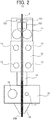
- FIG. 2 is a schematic view of a cross section of a discharge module of the three-dimensional fabricating apparatus in FIG. 1 .
- a three-dimensional fabricating apparatus 1 can fabricate a three-dimensional fabrication object of which a mold is complicated or which cannot be molded in injection molding.
- An interior of a casing 2 of the three-dimensional fabricating apparatus 1 is a processing space for fabricating a three-dimensional fabrication object M.
- a fabrication table 3 as a placing table is provided in the casing 2, and the three-dimensional fabrication object M is fabricated on the fabrication table 3.
- a long filament F including a resin composition in which thermoplastic resin is formed in a matrix is used.
- the filament F is an elongated wire-shaped solid material and is set on a reel 4 outside the casing 2 of the three-dimensional fabricating apparatus 1 in a wound state.
- the reel 4 is pulled by rotation of extruders 11 which are driving devices of the filament F to rotate without greatly applying a resistance force.
- a discharge module 10 (fabrication head) as a fabrication material discharge member is provided above the fabrication table 3 in the casing 2.
- the discharge module 10 is modularized by the extruder 11, a cooling block 12, a filament guide 14, a heating block 15, a discharge nozzle 18, an imaging module 101, a torsion rotation mechanism 102, and other components.
- the filament F is drawn by the extruders 11 to be supplied to the discharge module 10 of the three-dimensional fabricating apparatus 1.
- the imaging module 101 images a 360° image of the filament F drawn into the discharge module 10, that is, an omnidirectional image of a certain portion of the filament F.
- Two imaging modules are provided in the discharge module in FIG. 2 .
- the single imaging module 101 may image a 360° image of the filament F, for example, by using a reflection plate.
- a camera including an image forming optical system such as a lens, an imaging element such as a charge coupled device (CCD) sensor and a complementary metal oxide semiconductor (CMOS) sensor, and the like is exemplified.
- the torsion rotation mechanism 102 includes rollers and rotates the filament F drawn into the discharge module 10 in the width direction to restrict the direction of the filament F.
- a diameter measuring unit 103 measures widths between edges of the filament in two directions, i.e., the X-axis direction and the Y-axis direction from the image of the filament imaged by the imaging module 101 as diameters and outputs error information when detecting a nonstandard diameter.
- An output destination of the error information may be a display, a speaker, and other device.
- the diameter measuring unit 103 may be a circuit and a function implemented by processing of a CPU.
- the heating block 15 includes a heat source 16 such as a heater and a thermocouple 17 which controls a temperature of the heater, and heats and melts the filament F supplied to the discharge module 10 via a transfer path and supplies the filament F to the discharge nozzle 18.
- a heat source 16 such as a heater and a thermocouple 17 which controls a temperature of the heater, and heats and melts the filament F supplied to the discharge module 10 via a transfer path and supplies the filament F to the discharge nozzle 18.
- the cooling block 12 is provided above the heating block 15.
- the cooling block 12 includes cooling sources 13 and cools the filament.
- the cooling block 12 prevents reverse flow of the melted filament FM to the upper portion in the discharge module 10, an increase in a resistance to push out the filament, or clogging in the transfer path due to solidification of the filament.
- the filament guide 14 is provided between the heating block 15 and the cooling block 12.
- the discharge nozzle 18 which discharges the filament F that is a fabrication material is provided at a lower end portion of the discharge module 10.
- the discharge nozzle 18 linearly pushes out the melted or semi-molten filament FM supplied from the heating block 15 to discharge the filament FM on the fabrication table 3.
- the discharged filament FM is cooled and solidified to form a layer having a predetermined shape.
- the discharge nozzle 18 repeats the operation for linearly pushing out the melted or semi-molten filament FM and discharging the filament FM on the formed layer to laminate new layers. With this operation, a three-dimensional fabrication object can be obtained.
- two discharge nozzles are provided in the discharge module 10.
- a first discharge nozzle melts and discharges a filament including a model material forming the three-dimensional fabrication object
- a second discharge nozzle melts and discharges a filament including a support material.
- the second discharge nozzle is arranged in the back of the first discharge nozzle.
- the number of discharge nozzles is not limited to two and may be arbitrary.
- the support material discharged from the second discharge nozzle is normally different from the model material forming the three-dimensional fabrication object.
- a support portion including the support material is finally removed from a model portion including the model material.
- the filament including the support material and the filament including the model material are melted by the heating block 15 and pushed out and discharged from the discharge nozzles 18 to be sequentially laminated in layers.
- heating modules 20 which heat a lower layer of layers being formed by the discharge module 10 are provided.
- a laser light source 21 which emits laser is provided.
- the laser light source 21 irradiates a position immediately before the filament FM in the lower layer is discharged with the laser.
- the laser light source is not particularly limited. However, as the laser light source, a semiconductor laser is exemplified, and as an irradiation wavelength of the laser, 445 nm is exemplified.
- the discharge module 10 can move in the horizontal direction of the apparatus (X-axis direction) by a driving force of an X-axis driving motor 32.
- the X-axis drive shaft 31 moves along the Y-axis direction by a driving force of a Y-axis driving motor 33 together with the X-axis driving motor 32 so that the discharge module 10 and the heating module 20 move in the Y-axis direction.
- the fabrication table 3 moves in the vertical direction of the apparatus (Z-axis direction) by a driving force of a Z-axis driving motor 36.
- a heating unit for heating a laminated fabrication object may be provided in the fabrication table 3.
- a peripheral portion of the discharge nozzle 18 may be contaminated with melted resin.
- a cleaning brush 37 provided in the three-dimensional fabricating apparatus 1 periodically performs a cleaning operation relative to the peripheral portion of the discharge nozzle 18 to prevent resin from adhering at the front end of the discharge nozzle 18.
- the cleaning operation is performed before the temperature of the resin is sufficiently lowered.
- the cleaning brush 37 include a heat resistance member. Polishing powders generated at the time of the cleaning operation may be collected into a dust box 38 provided in the three-dimensional fabricating apparatus 1 and periodically discarded or may be discharged outside by providing a suction path.
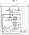
- FIG. 3 is a hardware configuration diagram of the three-dimensional fabricating apparatus according to an embodiment.
- the three-dimensional fabricating apparatus 1 includes a controller 100.
- the controller 100 includes a central processing unit (CPU), a circuit, or the like and electrically connected to each unit as illustrated in FIG. 3 .
- CPU central processing unit
- FIG. 3 is a hardware configuration diagram of the three-dimensional fabricating apparatus according to an embodiment.
- the three-dimensional fabricating apparatus 1 includes a controller 100.
- the controller 100 includes a central processing unit (CPU), a circuit, or the like and electrically connected to each unit as illustrated in FIG. 3 .
- CPU central processing unit
- an X-axis coordinate detection mechanism which detects an X-axis position of the discharge module 10 is provided.
- the detection result of the X-axis coordinate detection mechanism is sent to the controller 100.
- the controller 100 controls drive of the X-axis driving motor 32 based on the detection result and moves the discharge module 10 to a target position in the X-axis direction.
- a Y-axis coordinate detection mechanism which detects a Y-axis position of the discharge module 10 is provided.
- the detection result of the Y-axis coordinate detection mechanism is sent to the controller 100.
- the controller 100 controls drive of the Y-axis driving motor 33 based on the detection result and moves the discharge module 10 to a target position in the Y-axis direction.
- a Z-axis coordinate detection mechanism which detects a Z-axis position of the fabrication table 3 is provided.
- the detection result of the Z-axis coordinate detection mechanism is sent to the controller 100.
- the controller 100 controls drive of the Z-axis driving motor 36 based on the detection result and moves the fabrication table 3 to a target position in the Z-axis direction.
- controller 100 controls the movements of the discharge module 10 and the fabrication table 3 to move relative three-dimensional positions of the discharge module 10 and the fabrication table 3 to target three-dimensional positions.
- the controller 100 transmits control signals to driving units of the extruder 11, the cooling block 12, the discharge nozzle 18, the laser light source 21, the cleaning brush 37, a rotation stage RS, the imaging module 101, the torsion rotation mechanism 102, the diameter measuring unit 103, and a temperature sensor 104 to control the drive of these units.
- the rotation stage RS, a side surface cooling unit 39, the imaging module 101, the torsion rotation mechanism 102, the diameter measuring unit 103, and the temperature sensor 104 will be described later.
- FIG. 4 is a schematic diagram of an example of an operation for heating the lower layer.
- a method for heating the lower layer with a laser will be described.
- the laser light source 21 irradiates the position of the lower layer immediately before the filament FM is discharged with the laser to reheat the position.
- To reheat means to heat the filament FM again after the melted filament FM is cooled and solidified.
- the temperature of reheat is not particularly limited. However, the temperature is preferable equal to or higher than a temperature at which the filament FM of the lower layer melts.
- the temperature sensor 104 senses a temperature of the lower layer before heated.
- the temperature sensor 104 is arranged at an arbitrary position where the temperature sensor 104 can sense a lower layer surface before heated.
- the temperature sensor 104 is arranged in the back of the laser light source 21 in FIG. 4 .
- the temperature of the lower layer before heated is sensed by the temperature sensor 104 and an output of the laser is adjusted based on the sensing result so that the lower layer can be reheated to a temperature equal to or higher than a predetermined temperature.
- the temperature sensor 104 is arranged at an arbitrary position where the temperature sensor 104 can sense a heating surface.
- any known device may be used, and a contact type device or a non-contact type device may be used.
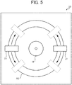
- FIG. 5 is a plan view of a heating module according to an embodiment as viewed from the side of the fabrication table 3.
- the heating modules 20 are attached to the rotation stage RS.
- the rotation stage RS rotates about the discharge nozzle 18.
- the laser light source 21 rotates and moves in accordance with the rotation of the rotation stage RS. With this movement, the laser light source 21 can irradiate the discharge position of the discharge nozzle 18 with laser light in advance even when the moving direction of the discharge nozzle 18 is changed.
- FIGS. 6A to 6C are schematic diagrams of states of the fabrication object at the time of forming the upper layer.
- a layer which is fabricated by the discharge module 10 is referred to as an upper layer Ln
- a layer below the fabricating layer is referred to as a lower layer Ln-1
- a layer below the lower layer Ln-1 is referred to as a lower layer Ln-2.
- Arrows in FIGS. 6A to 6C indicate a movement path (tool path) of the discharge module.
- the discharged filament is expressed by elliptic cylinders so as to recognize the tool path of the discharge module. Therefore, voids are formed between the filaments.
- FIG. 6A is a schematic diagram of a fabrication object when the upper layer is formed without reheating the lower layer. If the upper layer Ln is formed without reheating the lower layer Ln-1, the upper layer Ln can be formed in a state where the lower layer Ln-1 is solidified. Therefore, an outer surface OS is not deformed. However, in this case, sufficient adhesion strength between the upper layer Ln and the lower layer Ln-1 cannot be obtained.
- FIG. 6B is a schematic diagram of a fabrication object when the upper layer is formed while reheating the lower layer. If the upper layer Ln is formed while reheating the lower layer Ln-1, the upper layer Ln can be formed in a state where the lower layer Ln-1 is melted. Therefore, the outer surface OS is deformed.
- FIG. 6C is a schematic diagram of a fabrication object when the upper layer is formed while reheating the lower layer.
- the model portion M is supported by a support portion S. Therefore, the outer surface OS of the model portion M is not deformed.
- the upper layer Ln is formed in a state where the lower layer Ln-1 is partially remelted.
- the lower layer Ln-1 is partially remelted.
- entanglement of polymer between the upper layer Ln and the lower layer Ln-1 is promoted, and the strength of the fabrication object is enhanced.
- by appropriately setting the conditions of remelting it is possible to achieve both of shape accuracy and strength of the model portion in the lamination direction. A setting example of a remelting region and an effect in the present embodiment will be described later.
- the model material and the support material may be the same or may be different from each other.
- the model portion M and the support portion S include the same material, by controlling a strength of an interface of these portions, the portions can be separated from each other after fabrication.
- FIGS. 7A to 7C are schematic diagrams of states of the fabrication object at the time of forming the upper layer.
- the three-dimensional fabricating apparatus 1 reheats the surface of the model portion M of the lower layer Ln-1 and the surface of the support portion S except for an outer peripheral portion, forms a remelted portion RM, and forms the upper layer Ln.
- this method since a region of the model portion M on the side of the outer surface OS is remelted and fabricated, adhesiveness between the layers is improved, and the strength in the lamination direction is enhanced.
- the support portion S and the model portion M are hardly separated during fabrication, and fabrication accuracy is improved.
- the strength of the model portion M may decrease by mixing the support portion S into the model portion M.
- the mixture of the materials can be prevented by devising a movement of a contact member and cleaning the contact member.
- the releasability of the support portion S can be improved by using a material different from the model material and having a melting point lower than a melting point of the model material as the support material.
- the three-dimensional fabricating apparatus 1 forms the support portion S using the model material and the support material.
- the three-dimensional fabricating apparatus 1 arranges the support material in a region Ss of the support portion S on the side of the model portion M and arranges the model material in a region Sm on the outer periphery side.
- the three-dimensional fabricating apparatus 1 may form the model portion M and the region Sm in the support portion S by using the model material and subsequently flows the support material into gaps between the model material to fabricate the target object. Subsequently, the three-dimensional fabricating apparatus 1 forms the upper layer Ln while reheating the surface of the model portion M of the lower layer Ln-1 and the surface of the support portion S except for the outer peripheral portion.
- the fabrication method in FIG. 7B is suitable for a case where the releasability of the support portion S is excellent. Furthermore, the fabrication method in FIG. 7B is preferable in a point that, even in a case where the shape accuracy of the region Ss and strength as a structure are low, the region Sm supports the region Ss to supplement the shape accuracy and the strength of the region Ss.
- the three-dimensional fabricating apparatus 1 forms the upper layer Ln while reheating the surface of the model portion M except for the vicinity of the outer surface OS. According to this method, since the heat of the model portion M is hardly transmitted to the support portion S at the time of remelting, the shape of the support portion S is stabilized.
- the fabrication method in FIG. 7C is effective in that the shape of the model portion M is easily maintained and the releasability between the model portion M and the support portion S can be easily secured.
- the strength in the lamination direction is weaker than that in a case of the fabrication method for remelting the entire surface of the model portion M. Therefore, the fabrication method in FIG. 7C is effective in a case where a fabrication object of which an internal structure is strong is fabricated and in a case where emphasis is placed on fabrication accuracy and the releasability.
- FIGS. 8A to 8C are schematic diagrams of states of the fabrication object at the time of forming the upper layer.
- the fabrication method in FIG. 8A is different from the fabrication method in FIG. 7C in that a region in the surface of the model portion M which is not remelted is enlarged to a position farther away from the outer surface OS and the remelted portion RM is further reduced.
- the fabrication method in FIG. 8A is more effective than the fabrication method in FIG. 7C in that the shape of the model portion M can be maintained since the shape of the support portion S is stabilized.
- the strength of the model portion M in the lamination direction is further reduced.
- the fabrication method in FIG. 8B is different from the fabrication method in FIG. 7C in that the surface of the lower layer Ln-1 is reheated to the vicinity of the outer surface OS of the model portion M.
- the fabrication method in FIG. 8B is effective in a case where a melting point of the support material is higher than a melting point of the model material. According to the fabrication method in FIG. 8B , the strength of the model portion M in the lamination direction is stronger than the strength of the fabrication method in FIG. 7C .
- the three-dimensional fabricating apparatus 1 remelts the model portion M of the lower layer Ln-1 and forms the model portion M of the upper layer Ln. Since the support portion S is finally removed after fabrication, it is preferable that the support portion S has a strength enough not to be peeled off during the fabrication, and the strength as strong as the model material is not required. Therefore, it is preferable to select a material which can be more accurately laminated than the model material as the support material. By forming the support portion S of the upper layer Ln in a state where the lower layer Ln-1 is solidified, the fabrication accuracy of the support portion S is improved.
- the support portion S and the model portion M are independently formed. Therefore, the three-dimensional fabricating apparatus 1 can make a lamination pitch of the support portion S be narrower than a lamination pitch of the model portion M.
- the lamination pitch of the support portion S is half of the lamination pitch of the model portion M. Since the melted model material follows the shape of the support portion S, by narrowing the lamination pitch of the support portion S, the outer surface OS of the model portion M becomes smoother.
- the method in FIG. 8C is preferable in a case where the support portion S can be more accurately fabricated than the model portion M.
- FIGS. 9A to 9C are schematic diagrams of states of the fabrication object at the time of forming the upper layer.
- the fabrication method in FIG. 9A is different from that in FIG. 8B in that the model portion M of the upper layer Ln is formed after the support portion S of the upper layer Ln is formed in advance.
- the melting point of the support material is higher than the melting point of the model material, even when heated to the vicinity of the outer surface OS of the model portion M, the support portion S is not melted.
- the fabrication method in FIG. 9A a fabrication object with excellent releasability and a high strength in the lamination direction can be obtained, and the fabrication accuracy is improved.
- the fabrication method in FIG. 9B is different from the method in FIG. 7B in that the model portion M of the upper layer Ln is formed after the support portion S of the upper layer Ln is formed in advance. Furthermore, according to the method in FIG. 9B , even in a case where the shape accuracy of the region Ss and strength as a structure are low, the region Sm supports the region Ss to supplement the shape accuracy of the region Ss and the strength as a structure. However, according to the fabrication method in FIG. 9B , when the region Ss melts at the time of remelting, the releasability of the support portion S may be deteriorated.
- the fabrication method in FIG. 9C is different from that in FIG. 8A in that, after forming the outer peripheral side of the model portion M of the upper layer Ln in advance, the remaining portion of the model portion M of the upper layer Ln is fabricated. According to the fabrication method in FIG. 9C , only the model portion M is used for fabrication, the shape is stabilized, and the fabrication accuracy is improved. Furthermore, since the fabrication is performed while remelting a part of the side surface of the model portion M of the upper layer Ln, the strength of the model portion M is enhanced.
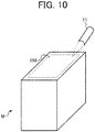
- FIG. 10 is a schematic view of an example of a reheating range according to the present embodiment.
- the three-dimensional fabricating apparatus 1 intentionally narrows the remelted portion RM without reheating the outer peripheral portion of the three-dimensional fabrication object M so as to maintain the shape of the fabrication object and improve adhesion between the laminated layers.
- FIG. 11 is a flowchart of fabrication processing according to an embodiment.
- the controller 100 of the three-dimensional fabricating apparatus 1 receives an input of data of a three-dimensional model.
- the data of the three-dimensional model is constructed by image data of each layer when the three-dimensional model is sliced at predetermined intervals.
- the controller 100 of the three-dimensional fabricating apparatus 1 drives the X-axis driving motor 32 or the Y-axis driving motor 33 to move the discharge module 10 in the X-axis or Y-axis direction. While the discharge module 10 moves, the controller 100 discharges the melted or semi-molten filament FM from the discharge nozzle 18 to the fabrication table 3 based on the image data of the lowermost layer of the input data of the three-dimensional model. Accordingly, the three-dimensional fabricating apparatus 1 forms a layer having a shape based on the image data on the fabrication table 3 (step S11).
- the controller 100 While the discharge module 10 moves, the controller 100 emits laser from the laser light source 21 based on the image data of the lowermost layer of layers which are not fabricated yet of the input data of the three-dimensional model. As a result, a laser irradiation position of the lower layer is remelted (step S12).
- the controller 100 may irradiate inside of a range indicated by the image data with the laser. Alternatively, for example, as in the fabrication methods in FIGS. 7A, 7B , and 9B , the controller 100 may emit the laser beyond the range indicated by the image data.
- a heating temperature of the lower layer in step S12 is controlled to be equal to or higher than a melting temperature of the filament.
- the controller 100 discharges the filament FM from the discharge nozzle 18 to the lower layer on the fabrication table 3 based on the image data of the lowermost layer of layers which are not fabricated yet of the input data of the three-dimensional model. As a result, a layer having a shape corresponding to the image data is formed on the lower layer (step S13). At this time, since the lower layer is remelted, adhesiveness of an interface between a layer to be fabricated and the lower layer is improved.
- the processing for remelting the lower layer in step S12 and the processing for forming the layer in step S13 may be overlapped.
- the three-dimensional fabricating apparatus 1 starts to discharge the filament FM from the start of processing for irradiating the lower layer with the laser and before completion of the irradiation of the entire irradiation range with the laser.
- the controller 100 of the three-dimensional fabricating apparatus 1 determines whether the layer formed in step S13 is the outermost layer (step S14).
- the outermost layer is a layer formed based on image data having the largest coordinate in the lamination direction (Z axis) of the data of the three-dimensional model. In a case where it has been determined as NO in step S14, the controller 100 of the three-dimensional fabricating apparatus 1 repeats the processing for remelting (step S12) and the processing for forming the layer (step S13) until the outermost layer is formed.
- step S14 the three-dimensional fabricating apparatus 1 terminates the fabrication processing.
- FIG. 12 is a schematic diagram of an operation for heating the lower layer according to an embodiment.
- the heating module 20 includes a hot air source 21'.
- a hot air source 21' As the hot air source 21' , a heater and a fan are exemplified.
- the hot air source 21' blows high-temperature hot air against the lower layer to heat and remelt the lower layer.
- the filament FM is discharged to the remelted lower layer to form the upper layer so that materials of the lower layer and the upper layer are mixed and the adhesiveness between the upper layer and the lower layer is improved.
- FIG. 13 is a schematic diagram of an operation for heating the lower layer according to an embodiment.
- the heating module 20 of the three-dimensional fabricating apparatus 1 is replaced with a heating module 20' .
- the heating module 20' includes a heating plate 28 which heats and pressurizes the lower layer of the three-dimensional fabrication object M, a heating block 25 which heats the heating plate 28, and a cooling block 22 which prevents heat conduction from the heating block 25.
- the heating block 25 includes a heat source 26 such as a heater and a thermocouple 27 which controls the temperature of the heating plate 28.
- the cooling block 22 includes cooling sources 23.
- a guide 24 is provided between the heating block 25 and the cooling block 22.
- the heating module 20' is heated to a high temperature by the heating block 25.
- the transfer path including the filament guide 14 and the like or the guide 24 have low thermal conductivity.
- the lower end of the heating plate 28 is arranged to be lower than the lower end of the discharge nozzle 18 by a single layer. While the discharge module 10 and the heating module 20 are scanned in an outline arrow direction in FIG. 13 and the filament is discharged, and at the same time, the heating plate 28 reheats the layer below the layer which is fabricated. As a result, a temperature difference between the fabricating layer and the layer below the fabricating layer decreases, and the materials of the layers are mixed. Therefore, the strength between the layers of the fabrication object is improved.
- a method for cooling the heated layer a method for setting an atmospheric temperature, a method for leaving the layer for a predetermined time, or a method using a fan and the like are exemplified.
- the lower layer is selectively heated without deforming the outer shape of the fabrication object, and next discharge is performed when the lower layer is remelted, so that the adhesion of the interface is improved.
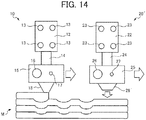
- FIG. 14 is a schematic diagram of the operation for heating the lower layer according to an embodiment.
- the heating plate 28 in the heating module 20' is replaced with a tap nozzle 28' .
- the tap nozzle 28' is heated by the heating block 25.
- the tap nozzle 28' heats and pressurizes the lower layer of the three-dimensional fabrication object M by a tap operation for repeatedly tapping the three-dimensional fabrication object M from above in the vertical direction by power of a motor and the like. With this operation, a temperature difference between the fabricating layer and the layer below the fabricating layer decreases, and the materials of the layers are mixed. Therefore, the strength between the layers of the fabrication object is improved.
- the filament FM is discharged from the discharge nozzle 18 so as to fill the surface of the lower layer recessed by the tap operation. By filling the recessed portion of the lower layer with the filament FM, the shape of the outermost layer is smoothly finished.
- FIG. 15 is a schematic diagram of the operation for heating the lower layer according to an embodiment.
- the heating module 20 includes the side surface cooling unit 39 which cools the side surface of the three-dimensional fabrication object M, that is, a surface parallel to the Z axis.
- a cooling source is not particularly limited as long as the cooling source is capable of cooling the side surface of the three-dimensional fabrication object M.
- a fan is exemplified.
- the outer peripheral portion of the three-dimensional fabrication object M When the outer peripheral portion of the three-dimensional fabrication object M is reheated without performing the processing for maintaining the outer shape, the outer shape is deformed, and the fabrication accuracy is deteriorated. Therefore, in the modification D of the embodiment, by reheating the outer peripheral portion of the three-dimensional fabrication object M while blowing cooling air against the side surface of the three-dimensional fabrication object M, the shape of the fabrication portion is maintained, and the materials can be laminated.
- FIGS. 16A and 16B are cross-sectional views of examples of the filament of which the material composition is unevenly distributed.
- a high-viscosity resin Rh is arranged on both sides of the filament F, and a low-viscosity resin R1 is arranged in the center portion.
- the high-viscosity resin Rh arranged on both sides of the filament F is not particularly limited.
- a resin formed to be highly viscous by compounding fillers such as alumina, carbon black, carbon fibers, and glass fibers can be exemplified.
- a resin of which a molecular weight is controlled may be used as the high-viscosity resin Rh.
- the low-viscosity resin R1 arranged in the center portion of the filament F is not particularly limited. However, a resin having a low molecular weight grade is exemplified.
- FIGS. 17A and 17B are cross-sectional views of a discharged object of the filament in FIGS. 16A and 16B .
- FIG. 18 is a cross-sectional view of a fabrication object fabricated by using the filament in FIGS. 16A and 16B .
- the fabrication object in FIG. 18 is obtained.
- the fabrication object in FIG. 18 since the high-viscosity resin is arranged in the outer peripheral portion, naturally, the shape of the fabrication object is hardly deformed.
- FIG. 16B another example of a filament of which a material composition is unevenly distributed is illustrated.
- the discharged object having the shape illustrated in FIG. 17B is obtained.
- the fabrication object in which the high-viscosity resin is arranged in the outer peripheral portion is obtained.
- the filament in FIG. 17B when used, a lower portion of the layer has high viscosity.
- the high-viscosity resin often has a melting point higher than a melting point of the low-viscosity resin.
- a heating device a laser and the like capable of heating a small spot is preferable.
- FIG. 19 is a schematic diagram of an example of a three-dimensional fabricating apparatus including a restricting device.
- the three-dimensional fabricating apparatus 1 includes an assist mechanism 41 as an example of a restricting device.
- the thickness of the single layer is about 0.10 to 0.30 mm. Therefore, the plate in the assist mechanism 41 is a thin plate such as a thickness gauge.
- the assist mechanism 41 is fixed to the discharge module 10 or a bracket which is indirectly fixed to the discharge module 10.
- the plate in the assist mechanism 41 be heated to a temperature higher than a normal temperature.
- a crystal resin is rapidly cooled when the normal-temperature plate has contact with the resin so that amorphization advances and a desired strength cannot be obtained.
- the viscosity is expressed by a function of the temperature and a shear velocity.
- Engineering plastic used in the Fused Filament Fabrication (FFF) or super engineering plastic exhibits a nonlinear behavior relative to a variable such as a temperature or a shear velocity. Therefore, even if the temperature is not equal to or higher than a melting point Tm of the resin, a shear resistance for the FFF method, that is, the viscosity of resin may be obtained.
- a shear resistance for the FFF method that is, the viscosity of resin may be obtained.
- S. 1 shear velocity
- composition of a resin by a filler may be an effective method for preventing the liquid drips.
- the method for adding the filler to the filament is preferable.
- the fabrication accuracy cannot be maintained even when the filler is added, it is preferable to restrict the side surface of the fabrication object.
- the filament of which the material composition is unevenly distributed it is preferable to restrict the direction of the filament to be introduced into the discharge module 10 so that the high-viscosity resin Rh is arranged in the outer peripheral portion of the fabrication object.
- FIG. 20 is a flowchart of an example of processing for restricting the direction of the filament.
- the imaging module 101 of the three-dimensional fabricating apparatus 1 images the filament to be introduced into the discharge module 10 and transmits the obtained image data to the controller 100.
- the controller 100 receives the image data of the filament transmitted by the imaging module 101 (step S21).
- the controller 100 analyzes the received image data of the filament and calculates a rotation amount (step S22).
- a calculation method for the rotation amount is not particularly limited. However, as the calculation method, a method for determining the rotation amount so that a boundary between the high-viscosity resin Rh and the low-viscosity resin R1 in the filament F is set to be a predetermined position is exemplified.
- the controller 100 determines the rotation amount of the filament so that the resin Rh is arranged to be unevenly distributed in the positive and negative directions of the Y axis.
- the controller 100 transmits a signal to rotate the filament to the torsion rotation mechanism 102 based on the determined rotation amount.
- the torsion rotation mechanism 102 rotates the filament based on the signal (step S23). With this movement, the filament is restricted in a desired direction.
- the high-viscosity resin is arranged on the outer side of the filament, in the transfer path, the flow velocity of the filament on the side of the wall is extremely slow and the high-viscosity resin is retained so that there is a case where the filament cannot be discharged in desired arrangement. Therefore, in a region on the downstream side of the heating block 25 in a conveyance path, that is, in a region to which a temperature equal to or higher than a melting point is applied, it is preferable that an inner wall of the transfer path be processed with fluorine and the like with high heat resistance. By forming a release layer in the transfer path, a frictional resistance between the melted resin and the inner wall of the transfer path is reduced, and the high-viscosity resin is hardly retained.
- the controller 100 preferably performs feedforward control so as to prevent control delay.
- the controller 100 controls the driving of the torsion rotation mechanism 102 so that the direction of the filament is switched at a timing when a traveling direction of the discharge module 10 is curved.
- the controller 100 controls the driving of the torsion rotation mechanism 102 in a stepwise manner in consideration of the time lag.
- the controller 100 restrict a cumulative torsion amount of the filament to, for example, ⁇ 180° from a reference angle.
- a mechanism capable of rotating the entire discharge module 10 may be used instead of a mechanism for rotating the filament so that the resin is arranged in a desired state in the discharged object.
- the thermocouple 17 for controlling the heat source 16 a plurality of wiring systems such as wiring of the heat source 16, wiring of the cooling source 13, and an overheat protector are simultaneously rotated, the wiring is more complicated than the rotation direction of the filament.
- FIG. 21 is a schematic diagram of a fabrication and surface treatment operation according to an embodiment.
- the three-dimensional fabricating apparatus 1 includes a heating module 20''.
- the heating module 20'' includes a horn 30 which heats and pressurizes the three-dimensional fabrication object M.
- An ultrasonic vibration device is provided in the three-dimensional fabricating apparatus 1.
- the horn 30 moves downward from above of a lamination surface of the three-dimensional fabrication object M by the Z-axis driving motor and applies a pressure to the lamination surface. With this movement, ultrasonic vibration generated by the ultrasonic vibration device is transmitted to the three-dimensional fabrication object M.
- the ultrasonic vibration is transmitted to the three-dimensional fabrication object M, the upper layer Ln and the lower layer Ln-1 of the three-dimensional fabrication object M are welded and joined.
- the number of horns 30 is not limited to one and is appropriately selected. In a case where the plurality of horns 30 is provided, the shapes of the horns are not uniformed, and the horns having different shapes may be mounted.
- FIG. 22 is a schematic diagram of a cooling operation according to an embodiment.
- the three-dimensional fabricating apparatus 1 includes the side surface cooling unit 39 as in the modification D.
- a cooling source is not particularly limited as long as the cooling source is capable of cooling the side surface of the three-dimensional fabrication object M.
- a fan is exemplified.
- a method for setting an atmospheric temperature, a method for leaving the side surface for a predetermined time, and the like are exemplified.
- the side surface cooling unit 39 cools the side surface of the model portion M.
- FIG. 23 is a flowchart of fabrication processing according to an embodiment and illustrates steps S11 and S13 in FIG. 11 in detail.
- the three-dimensional fabricating apparatus 1 starts the processing in FIG. 23 .
- the discharge module 10 of the three-dimensional fabricating apparatus 1 discharges a melted filament to form the model portion M.
- step S22 the side surface cooling unit 39 cools the formed model portion M to solidify the model portion M.
- the side surface cooling unit 39 may cool a portion other than the model portion formed in step S21. For example, in a case where a second layer and subsequent layers are formed, the lower layer reheated and melted of the model portion which has been already formed may be cooled. Furthermore, the side surface cooling unit 39 may cool the entire model portion M and may cool a region of the model portion M having contact with the support portion S.
- the three-dimensional fabricating apparatus 1 may include the temperature sensor 104 and may obtain the temperature of the model portion M to adjust a cooling amount of the side surface cooling unit 39.
- step S23 forms the support portion S in the same layer as the model portion M formed in step S21.
- step S23 the processing for forming the single layer is terminated, and the processing for remelting the lower layer (step S12) or the processing for determining whether to form the next layer (step S14) is performed.
- the support portion S is formed after cooling and solidifying the model portion M, the model material and the support material are not mixed, and the support portion S can be easily removed.
- the discharge module 10 (example of discharger) of the three-dimensional fabricating apparatus 1 (example of fabricating apparatus) according to the embodiment discharges the melted filament (example of fabrication material) and forms a fabrication material layer.
- the heating module 20 (example of heating device) of the three-dimensional fabricating apparatus 1 heats the formed fabrication material layer.
- the discharge module 10 discharges the melted filament with respect to the heated fabrication material layer to laminate the fabrication material layers and perform fabrication.
- the materials of the layers are mixed by discharging the filament to the remelted fabrication material layer (lower layer) and laminating the fabrication material layer (upper layer), the strength of the fabrication object in the lamination direction can be enhanced. Furthermore, by the processing for laminating the upper layer, the fabrication object can be fabricated without affecting visibility of the outer shape.
- the heating module 20 of the three-dimensional fabricating apparatus 1 selectively heats a predetermined region of the fabrication material layer. As a result, the fabrication can be performed while maintaining the shape of the fabrication object.
- the rotation stage RS (example of conveying device) of the three-dimensional fabricating apparatus 1 conveys the heating module 20 so as to heat a predetermined position from different directions. With this operation, the heating module 20 can heat the fabrication material layer following the movement of the discharge module 10.
- the three-dimensional fabricating apparatus 1 includes the temperature sensor 104 (example of measuring device) which measures the temperature of the fabrication material layer heated by the heating module 20.
- the heating module 20 heats the fabrication material layer based on the temperature measured by the temperature sensor 104. With this operation, the three-dimensional fabricating apparatus 1 can appropriately reheat the fabrication material layer according to desired characteristics such as adhesion strength between the layers or the fabrication accuracy.
- the heating module 20 may be the laser light source 21 (example of light source irradiating device) which emits laser light. As a result, the heating module 20 can selectively heat the fabrication object without having contact with the fabrication object.
- the heating module 20 may be a hot air source (example of air blower) which blows heated air. Accordingly, the heating module 20 can selectively heat the fabrication object without having contact with the fabrication object.
- a hot air source example of air blower
- the heating module 20' may be the heating plate 28 or the tap nozzle 28' (example of member) which has contact with and heats the fabrication material layer. Accordingly, the heating module 20' can selectively heat the fabrication object.
- the three-dimensional fabricating apparatus 1 may include the plurality of heating modules 20. Accordingly, even when the scanning direction of the discharge module 10 is changed, any one of the heating modules 20 can heat the fabrication object. Therefore, a fabrication time is shortened.
- the side surface cooling unit 39 (example of cooler)) of the three-dimensional fabricating apparatus 1 cools the outer peripheral portion of the fabrication object including the fabrication material. Accordingly, the three-dimensional fabricating apparatus 1 can fabricate the fabrication object while maintaining the shape of the fabrication object.
- the support portion S can be easily removed after fabrication while maintaining the strength of the fabrication object.
- a plurality of materials having different viscosities is arranged in the filament. Accordingly, the discharge module 10 can discharge the filament so that the material with the lower viscosity is arranged in the outer peripheral portion, under the control by the controller 100.
- the assist mechanism 41 (example of supporting member) of the three-dimensional fabricating apparatus 1 supports the formed fabrication material layer. Accordingly, the fabrication can be performed while maintaining the shape of the formed fabrication material layer.
Landscapes
- Chemical & Material Sciences (AREA)
- Engineering & Computer Science (AREA)
- Materials Engineering (AREA)
- Manufacturing & Machinery (AREA)
- Physics & Mathematics (AREA)
- Mechanical Engineering (AREA)
- Optics & Photonics (AREA)
Applications Claiming Priority (1)
| Application Number | Priority Date | Filing Date | Title |
|---|---|---|---|
| JP2018044480A JP7023145B2 (ja) | 2018-03-12 | 2018-03-12 | 造形装置および造形方法 |
Publications (1)
| Publication Number | Publication Date |
|---|---|
| EP3539751A1 true EP3539751A1 (de) | 2019-09-18 |
Family
ID=65717714
Family Applications (1)
| Application Number | Title | Priority Date | Filing Date |
|---|---|---|---|
| EP19160163.2A Withdrawn EP3539751A1 (de) | 2018-03-12 | 2019-03-01 | Herstellungsvorrichtung und herstellungsverfahren |
Country Status (2)
| Country | Link |
|---|---|
| EP (1) | EP3539751A1 (de) |
| JP (1) | JP7023145B2 (de) |
Cited By (2)
| Publication number | Priority date | Publication date | Assignee | Title |
|---|---|---|---|---|
| EP3685996A1 (de) * | 2019-01-23 | 2020-07-29 | Ricoh Company, Ltd. | Herstellungsvorrichtung, system und herstellungsverfahren |
| CN112406103A (zh) * | 2020-10-29 | 2021-02-26 | 王勇 | 一种用于提高3d打印模型完整度的卸料辅助机构 |
Families Citing this family (2)
| Publication number | Priority date | Publication date | Assignee | Title |
|---|---|---|---|---|
| JP7446794B2 (ja) * | 2019-11-29 | 2024-03-11 | キヤノン株式会社 | 三次元造形物の製造方法、および三次元造形装置 |
| JP7757786B2 (ja) * | 2021-12-28 | 2025-10-22 | セイコーエプソン株式会社 | 三次元造形装置 |
Citations (6)
| Publication number | Priority date | Publication date | Assignee | Title |
|---|---|---|---|---|
| WO2004050323A1 (en) * | 2002-12-03 | 2004-06-17 | Objet Geometries Ltd. | Process of and apparatus for three-dimensional printing |
| US20170072626A1 (en) * | 2015-09-14 | 2017-03-16 | Xerox Corporation | Thermal management methods and apparatus for producing uniform material deposition and curing for high speed three-dimensional printing |
| JP2017170648A (ja) | 2016-03-18 | 2017-09-28 | 富士ゼロックス株式会社 | 三次元造形装置及び三次元造形プログラム |
| WO2018044399A1 (en) * | 2016-08-30 | 2018-03-08 | Rize Inc. | Method of fabricating a three-dimensional object with removable support structure |
| WO2019093330A1 (en) * | 2017-11-09 | 2019-05-16 | Ricoh Company, Ltd. | Fabricating apparatus and method for manufacturing fabrication object |
| EP3530437A1 (de) * | 2018-02-22 | 2019-08-28 | Ricoh Company, Ltd. | Herstellungsvorrichtung, herstellungsverfahren und herstellungssystem |
Family Cites Families (5)
| Publication number | Priority date | Publication date | Assignee | Title |
|---|---|---|---|---|
| US20030151167A1 (en) * | 2002-01-03 | 2003-08-14 | Kritchman Eliahu M. | Device, system and method for accurate printing of three dimensional objects |
| DE102015111504A1 (de) * | 2015-07-15 | 2017-01-19 | Apium Additive Technologies Gmbh | 3D-Druckvorrichtung |
| JP6843968B2 (ja) * | 2016-08-22 | 2021-03-17 | ストラタシス,インコーポレイテッド | 多軸ロボットビルドシステムを用いて3d部品を印刷する方法及び部品のオーブン外3d印刷の方法 |
| JP7005426B2 (ja) * | 2017-11-09 | 2022-01-21 | エス.ラボ株式会社 | 造形装置及び造形物の製造方法 |
| JP7019465B2 (ja) * | 2018-03-12 | 2022-02-15 | 三菱重工業株式会社 | 三次元積層造形方法および三次元積層造形装置 |
-
2018
- 2018-03-12 JP JP2018044480A patent/JP7023145B2/ja active Active
-
2019
- 2019-03-01 EP EP19160163.2A patent/EP3539751A1/de not_active Withdrawn
Patent Citations (6)
| Publication number | Priority date | Publication date | Assignee | Title |
|---|---|---|---|---|
| WO2004050323A1 (en) * | 2002-12-03 | 2004-06-17 | Objet Geometries Ltd. | Process of and apparatus for three-dimensional printing |
| US20170072626A1 (en) * | 2015-09-14 | 2017-03-16 | Xerox Corporation | Thermal management methods and apparatus for producing uniform material deposition and curing for high speed three-dimensional printing |
| JP2017170648A (ja) | 2016-03-18 | 2017-09-28 | 富士ゼロックス株式会社 | 三次元造形装置及び三次元造形プログラム |
| WO2018044399A1 (en) * | 2016-08-30 | 2018-03-08 | Rize Inc. | Method of fabricating a three-dimensional object with removable support structure |
| WO2019093330A1 (en) * | 2017-11-09 | 2019-05-16 | Ricoh Company, Ltd. | Fabricating apparatus and method for manufacturing fabrication object |
| EP3530437A1 (de) * | 2018-02-22 | 2019-08-28 | Ricoh Company, Ltd. | Herstellungsvorrichtung, herstellungsverfahren und herstellungssystem |
Cited By (2)
| Publication number | Priority date | Publication date | Assignee | Title |
|---|---|---|---|---|
| EP3685996A1 (de) * | 2019-01-23 | 2020-07-29 | Ricoh Company, Ltd. | Herstellungsvorrichtung, system und herstellungsverfahren |
| CN112406103A (zh) * | 2020-10-29 | 2021-02-26 | 王勇 | 一种用于提高3d打印模型完整度的卸料辅助机构 |
Also Published As
| Publication number | Publication date |
|---|---|
| JP2019155697A (ja) | 2019-09-19 |
| JP7023145B2 (ja) | 2022-02-21 |
Similar Documents
| Publication | Publication Date | Title |
|---|---|---|
| JP7005426B2 (ja) | 造形装置及び造形物の製造方法 | |
| JP7122794B2 (ja) | 造形装置、造形方法および造形システム | |
| JP7058140B2 (ja) | 造形装置、造形方法および造形システム | |
| JP7058141B2 (ja) | 造形装置、造形方法および造形システム | |
| EP3539751A1 (de) | Herstellungsvorrichtung und herstellungsverfahren | |
| WO2019093330A1 (en) | Fabricating apparatus and method for manufacturing fabrication object | |
| JP7376320B2 (ja) | 造形装置、造形方法および造形システム | |
| JP6832223B2 (ja) | 積層造形によって印刷された部分における層間接着性の向上 | |
| JP7264651B2 (ja) | 造形装置、システム、造形方法およびプログラム | |
| US20200262153A1 (en) | Fabricating apparatus, fabricating method, and fabricating system | |
| JP7075778B2 (ja) | 造形装置、造形方法および造形システム | |
| JP7531040B2 (ja) | 造形装置 | |
| JP6850431B2 (ja) | 三次元造形装置 | |
| US20200164574A1 (en) | Modeling device and method | |
| CN106696250A (zh) | 一种光纤传感构件的制备装置及方法 | |
| JP2019155885A (ja) | 3次元造形装置 | |
| JP2020131680A (ja) | 造形装置及び造形方法 | |
| JP2019142157A (ja) | 造形装置および造形方法 | |
| US20240351279A1 (en) | Print head design for additive manufacturing using continuous fibers and thermoplastic matrix materials for cutting in the hot zone of the print head by an axial or rotational movement | |
| JP7154117B2 (ja) | 造形装置、造形方法、及び造形プログラム | |
| JP7291259B2 (ja) | 造形装置 | |
| JP2019136977A (ja) | 造形装置 | |
| KR102926091B1 (ko) | 적층헤드의 스크류 회전 제어가 용이한 3d 프린팅 장치 및 적층헤드의 스크류 회전 제어 방법 | |
| JP2020124904A (ja) | 造形装置及び方法 | |
| JP2020151928A (ja) | 造形装置、造形方法及び造形システム |
Legal Events
| Date | Code | Title | Description |
|---|---|---|---|
| PUAI | Public reference made under article 153(3) epc to a published international application that has entered the european phase |
Free format text: ORIGINAL CODE: 0009012 |
|
| STAA | Information on the status of an ep patent application or granted ep patent |
Free format text: STATUS: REQUEST FOR EXAMINATION WAS MADE |
|
| 17P | Request for examination filed |
Effective date: 20190301 |
|
| AK | Designated contracting states |
Kind code of ref document: A1 Designated state(s): AL AT BE BG CH CY CZ DE DK EE ES FI FR GB GR HR HU IE IS IT LI LT LU LV MC MK MT NL NO PL PT RO RS SE SI SK SM TR |
|
| AX | Request for extension of the european patent |
Extension state: BA ME |
|
| STAA | Information on the status of an ep patent application or granted ep patent |
Free format text: STATUS: EXAMINATION IS IN PROGRESS |
|
| 17Q | First examination report despatched |
Effective date: 20210409 |
|
| RAP1 | Party data changed (applicant data changed or rights of an application transferred) |
Owner name: S. LAB INC. |
|
| STAA | Information on the status of an ep patent application or granted ep patent |
Free format text: STATUS: THE APPLICATION IS DEEMED TO BE WITHDRAWN |
|
| 18D | Application deemed to be withdrawn |
Effective date: 20210820 |