EP3538683B1 - Installation de dépôt par évaporation d'un revêtement sur des articles optiques - Google Patents
Installation de dépôt par évaporation d'un revêtement sur des articles optiques Download PDFInfo
- Publication number
- EP3538683B1 EP3538683B1 EP17797610.7A EP17797610A EP3538683B1 EP 3538683 B1 EP3538683 B1 EP 3538683B1 EP 17797610 A EP17797610 A EP 17797610A EP 3538683 B1 EP3538683 B1 EP 3538683B1
- Authority
- EP
- European Patent Office
- Prior art keywords
- optical articles
- installation according
- arm
- rotary support
- track
- Prior art date
- Legal status (The legal status is an assumption and is not a legal conclusion. Google has not performed a legal analysis and makes no representation as to the accuracy of the status listed.)
- Active
Links
Images



Classifications
-
- C—CHEMISTRY; METALLURGY
- C23—COATING METALLIC MATERIAL; COATING MATERIAL WITH METALLIC MATERIAL; CHEMICAL SURFACE TREATMENT; DIFFUSION TREATMENT OF METALLIC MATERIAL; COATING BY VACUUM EVAPORATION, BY SPUTTERING, BY ION IMPLANTATION OR BY CHEMICAL VAPOUR DEPOSITION, IN GENERAL; INHIBITING CORROSION OF METALLIC MATERIAL OR INCRUSTATION IN GENERAL
- C23C—COATING METALLIC MATERIAL; COATING MATERIAL WITH METALLIC MATERIAL; SURFACE TREATMENT OF METALLIC MATERIAL BY DIFFUSION INTO THE SURFACE, BY CHEMICAL CONVERSION OR SUBSTITUTION; COATING BY VACUUM EVAPORATION, BY SPUTTERING, BY ION IMPLANTATION OR BY CHEMICAL VAPOUR DEPOSITION, IN GENERAL
- C23C14/00—Coating by vacuum evaporation, by sputtering or by ion implantation of the coating forming material
- C23C14/04—Coating on selected surface areas, e.g. using masks
- C23C14/042—Coating on selected surface areas, e.g. using masks using masks
- C23C14/044—Coating on selected surface areas, e.g. using masks using masks using masks to redistribute rather than totally prevent coating, e.g. producing thickness gradient
-
- B—PERFORMING OPERATIONS; TRANSPORTING
- B05—SPRAYING OR ATOMISING IN GENERAL; APPLYING FLUENT MATERIALS TO SURFACES, IN GENERAL
- B05B—SPRAYING APPARATUS; ATOMISING APPARATUS; NOZZLES
- B05B12/00—Arrangements for controlling delivery; Arrangements for controlling the spray area
- B05B12/16—Arrangements for controlling delivery; Arrangements for controlling the spray area for controlling the spray area
- B05B12/20—Masking elements, i.e. elements defining uncoated areas on an object to be coated
- B05B12/22—Masking elements, i.e. elements defining uncoated areas on an object to be coated movable relative to the spray area
-
- C—CHEMISTRY; METALLURGY
- C23—COATING METALLIC MATERIAL; COATING MATERIAL WITH METALLIC MATERIAL; CHEMICAL SURFACE TREATMENT; DIFFUSION TREATMENT OF METALLIC MATERIAL; COATING BY VACUUM EVAPORATION, BY SPUTTERING, BY ION IMPLANTATION OR BY CHEMICAL VAPOUR DEPOSITION, IN GENERAL; INHIBITING CORROSION OF METALLIC MATERIAL OR INCRUSTATION IN GENERAL
- C23C—COATING METALLIC MATERIAL; COATING MATERIAL WITH METALLIC MATERIAL; SURFACE TREATMENT OF METALLIC MATERIAL BY DIFFUSION INTO THE SURFACE, BY CHEMICAL CONVERSION OR SUBSTITUTION; COATING BY VACUUM EVAPORATION, BY SPUTTERING, BY ION IMPLANTATION OR BY CHEMICAL VAPOUR DEPOSITION, IN GENERAL
- C23C14/00—Coating by vacuum evaporation, by sputtering or by ion implantation of the coating forming material
- C23C14/22—Coating by vacuum evaporation, by sputtering or by ion implantation of the coating forming material characterised by the process of coating
- C23C14/50—Substrate holders
- C23C14/505—Substrate holders for rotation of the substrates
-
- C—CHEMISTRY; METALLURGY
- C23—COATING METALLIC MATERIAL; COATING MATERIAL WITH METALLIC MATERIAL; CHEMICAL SURFACE TREATMENT; DIFFUSION TREATMENT OF METALLIC MATERIAL; COATING BY VACUUM EVAPORATION, BY SPUTTERING, BY ION IMPLANTATION OR BY CHEMICAL VAPOUR DEPOSITION, IN GENERAL; INHIBITING CORROSION OF METALLIC MATERIAL OR INCRUSTATION IN GENERAL
- C23C—COATING METALLIC MATERIAL; COATING MATERIAL WITH METALLIC MATERIAL; SURFACE TREATMENT OF METALLIC MATERIAL BY DIFFUSION INTO THE SURFACE, BY CHEMICAL CONVERSION OR SUBSTITUTION; COATING BY VACUUM EVAPORATION, BY SPUTTERING, BY ION IMPLANTATION OR BY CHEMICAL VAPOUR DEPOSITION, IN GENERAL
- C23C14/00—Coating by vacuum evaporation, by sputtering or by ion implantation of the coating forming material
- C23C14/22—Coating by vacuum evaporation, by sputtering or by ion implantation of the coating forming material characterised by the process of coating
- C23C14/54—Controlling or regulating the coating process
- C23C14/542—Controlling the film thickness or evaporation rate
-
- G—PHYSICS
- G02—OPTICS
- G02C—SPECTACLES; SUNGLASSES OR GOGGLES INSOFAR AS THEY HAVE THE SAME FEATURES AS SPECTACLES; CONTACT LENSES
- G02C7/00—Optical parts
- G02C7/02—Lenses; Lens systems ; Methods of designing lenses
- G02C7/024—Methods of designing ophthalmic lenses
-
- B—PERFORMING OPERATIONS; TRANSPORTING
- B05—SPRAYING OR ATOMISING IN GENERAL; APPLYING FLUENT MATERIALS TO SURFACES, IN GENERAL
- B05B—SPRAYING APPARATUS; ATOMISING APPARATUS; NOZZLES
- B05B13/00—Machines or plants for applying liquids or other fluent materials to surfaces of objects or other work by spraying, not covered by groups B05B1/00 - B05B11/00
- B05B13/02—Means for supporting work; Arrangement or mounting of spray heads; Adaptation or arrangement of means for feeding work
- B05B13/0221—Means for supporting work; Arrangement or mounting of spray heads; Adaptation or arrangement of means for feeding work characterised by the means for moving or conveying the objects or other work, e.g. conveyor belts
- B05B13/0228—Means for supporting work; Arrangement or mounting of spray heads; Adaptation or arrangement of means for feeding work characterised by the means for moving or conveying the objects or other work, e.g. conveyor belts the movement of the objects being rotative
-
- B—PERFORMING OPERATIONS; TRANSPORTING
- B05—SPRAYING OR ATOMISING IN GENERAL; APPLYING FLUENT MATERIALS TO SURFACES, IN GENERAL
- B05D—PROCESSES FOR APPLYING FLUENT MATERIALS TO SURFACES, IN GENERAL
- B05D1/00—Processes for applying liquids or other fluent materials
- B05D1/002—Processes for applying liquids or other fluent materials the substrate being rotated
-
- B—PERFORMING OPERATIONS; TRANSPORTING
- B05—SPRAYING OR ATOMISING IN GENERAL; APPLYING FLUENT MATERIALS TO SURFACES, IN GENERAL
- B05D—PROCESSES FOR APPLYING FLUENT MATERIALS TO SURFACES, IN GENERAL
- B05D1/00—Processes for applying liquids or other fluent materials
- B05D1/32—Processes for applying liquids or other fluent materials using means for protecting parts of a surface not to be coated, e.g. using stencils, resists
-
- B—PERFORMING OPERATIONS; TRANSPORTING
- B25—HAND TOOLS; PORTABLE POWER-DRIVEN TOOLS; MANIPULATORS
- B25J—MANIPULATORS; CHAMBERS PROVIDED WITH MANIPULATION DEVICES
- B25J11/00—Manipulators not otherwise provided for
- B25J11/0075—Manipulators for painting or coating
-
- G—PHYSICS
- G02—OPTICS
- G02B—OPTICAL ELEMENTS, SYSTEMS OR APPARATUS
- G02B1/00—Optical elements characterised by the material of which they are made; Optical coatings for optical elements
- G02B1/10—Optical coatings produced by application to, or surface treatment of, optical elements
-
- G—PHYSICS
- G02—OPTICS
- G02C—SPECTACLES; SUNGLASSES OR GOGGLES INSOFAR AS THEY HAVE THE SAME FEATURES AS SPECTACLES; CONTACT LENSES
- G02C7/00—Optical parts
- G02C7/02—Lenses; Lens systems ; Methods of designing lenses
-
- G—PHYSICS
- G03—PHOTOGRAPHY; CINEMATOGRAPHY; ANALOGOUS TECHNIQUES USING WAVES OTHER THAN OPTICAL WAVES; ELECTROGRAPHY; HOLOGRAPHY
- G03F—PHOTOMECHANICAL PRODUCTION OF TEXTURED OR PATTERNED SURFACES, e.g. FOR PRINTING, FOR PROCESSING OF SEMICONDUCTOR DEVICES; MATERIALS THEREFOR; ORIGINALS THEREFOR; APPARATUS SPECIALLY ADAPTED THEREFOR
- G03F7/00—Photomechanical, e.g. photolithographic, production of textured or patterned surfaces, e.g. printing surfaces; Materials therefor, e.g. comprising photoresists; Apparatus specially adapted therefor
- G03F7/70—Microphotolithographic exposure; Apparatus therefor
- G03F7/70691—Handling of masks or workpieces
- G03F7/70733—Handling masks and workpieces, e.g. exchange of workpiece or mask, transport of workpiece or mask
-
- Y—GENERAL TAGGING OF NEW TECHNOLOGICAL DEVELOPMENTS; GENERAL TAGGING OF CROSS-SECTIONAL TECHNOLOGIES SPANNING OVER SEVERAL SECTIONS OF THE IPC; TECHNICAL SUBJECTS COVERED BY FORMER USPC CROSS-REFERENCE ART COLLECTIONS [XRACs] AND DIGESTS
- Y10—TECHNICAL SUBJECTS COVERED BY FORMER USPC
- Y10S—TECHNICAL SUBJECTS COVERED BY FORMER USPC CROSS-REFERENCE ART COLLECTIONS [XRACs] AND DIGESTS
- Y10S438/00—Semiconductor device manufacturing: process
- Y10S438/942—Masking
- Y10S438/943—Movable
Definitions
- the present invention relates to an installation for deposition by evaporation of a coating on optical articles and more specifically to a distribution mask.
- optical article in particular an insert, a plate, a semi-finished lens, a lens, corrective or not, which can be used as a spectacle lens, for example for spectacles, in particular sunglasses or masks or the like.
- This article is in particular made of glass or plastic.
- the optical article can be produced in one or more layers forming an assembly.
- an optical article such as for example an optical lens
- a complex manufacturing process which includes, for example, the manufacture of an insert or a wafer (also called a “wafer”), for example in plastic material by a process of injection into a mould.
- one or more surface treatments are applied, for example.
- These surface treatments can be an antireflection treatment and/or a hardening treatment, and/or a color application treatment.
- the treatment enclosure implemented for this purpose comprises, internally, a support which, rotatably mounted, has, distributed around from its axis of rotation, a plurality of locations suitable for each receiving an optical article to be treated, and which, in practice, is generally in the form of a spherical cap or a dome.
- an emitting source from which the material to be deposited is evaporated according to an evaporation cone.
- this emitting source is for example constituted by a support on which the material to be evaporated is placed, for example a crucible or a plate, and, for its evaporation, the material is for example subjected to heating by Joule effect, to electron bombardment, or sputtering effect.
- the evaporation cone can be considered as the envelope of the molecules sent in the direction of the optical articles to be treated.
- one of the difficulties to be overcome is that, for obvious reasons, in particular related to the evaporation cone, it is important that the deposit(s) made take place uniformly on each of the optical articles independently of their location in the rotary dome and in particular independently of the distance from the axis of rotation of the dome so that they are identical for all of them.
- the evaporation cone of a material is in practice not isotropic. Indeed, the density of the material is generally greater in the center of the cone than on the side edges.
- the density of the molecules emitted is not homogeneous and the density is more important close to the axis of rotation and less important when moving away from the axis of rotation.
- a first response to this problem is the cap shape of the rotary support or dome.
- the configuration of the distribution cache thus implemented is such that the span of this distribution cache is, for example, greater near the axis of rotation of the rotary support than at a distance from this axis of rotation. .
- the deposition of a layer of material on the various treated optical articles can be done substantially along the same thickness for all of them.
- the center of the optical article is at a different distance from the source relative to the edge of the optical article.
- the distance from the center can be closer or farther from the source than the edge depending on whether the coating is applied to a convex or respectively concave surface of the optical article.
- This non-uniformity can reduce the performance of the anti-reflective coating thus produced, introduce a variation in the distribution of a color which then no longer appears uniform, or introduce an iridescence in the form of reflections in alternating bands of color at certain angles d. 'impact.
- the non-uniformity defects of the different layers add up and impact the performance of such a functional multi-layer, in particular on the edges.
- the caches known from the state of the art do not make it possible to solve this problem and mainly address only a variation in thickness from one optical glass to another, but not a lack of uniformity at the level of the same optical article.
- the object of the invention is therefore to propose a distribution mask for controlling the deposition by evaporation of a coating on an optical article which makes it possible to better standardize, at least on a band portion going from a peripheral edge to an edge opposite through the center, a surface treatment for an optical article having a significant curvature or sphericity, and in particular to standardize, at lower cost, the surface treatments deposited on a multiplicity of optical articles.
- peripheral portions of the optical articles installed in the housings remain exposed to the emitting source of material while the central portion is hidden and cannot receive the molecules of the material to be deposited.
- individual optical article housings are arranged in concentric tracks and the at least one arm is arranged centrally opposite the concentric track.
- the at least one arm is in particular curved, extending along an associated track.
- the width of the arm perpendicular to the associated track can be configured so that the footprint projected from the arm on the optical articles of the associated track has a width perpendicular to the associated track which is less than the width of the optical articles when these are carried by the rotary support so that said arm prevents the deposition of molecules in a central portion of the optical articles and allows the deposition of molecules in two lateral portions of the optical articles arranged on either side with respect to the associated track.
- the width of the arm extends in a direction perpendicular to the track and is in particular less than the width of the optical articles intended to be carried by the rotary support.
- the cover to comprise an arm for each track of the rotary support.
- the width perpendicular to the associated track of the footprint projected from the arm onto the optical articles of the associated track is for example between 60% and 95%, in particular between 80% and 90% and more particularly 85% of the width of the optical articles carried by the rotatable support.
- Each arm (34) has for example a rounded end.
- the radius of curvature of the rounded ends corresponds for example to the radius of curvature of the optical article to receive the coating.
- the mask can comprise a central portion whose shape is configured to compensate for an inhomogeneity of the evaporation cone between the different optical article housing tracks.
- the installation may comprise for each track of housings a first and a second arm extending the central portion symmetrically on either side of the central portion.
- the central portion may have an elliptical or trapezoidal shape.
- the length of the arms increases for example with the distance of the concentric associated tracks with respect to the axis of rotation of the rotary support.
- the length of the pairs of curved arms taking into account a central portion if the latter is present, angularly covers a sector of a circle comprised in particular between 60° and 160°, in particular between 80° and 140°.
- the ends of the arms can fit into a shape corresponding to the layout of the central portion.
- the rotary support has in particular a concave shape so that the optical article housings are arranged at an equal distance from the emitting source.
- the figure 1 shows an optical article 10 to which any treatment is to be applied.
- This optical article 10 can preferably be an ophthalmic article, and in particular, an insert or contour disc, a wafer, a semi-finished lens, a lens, corrective or not, which can be used as a spectacle lens, for example. for glasses, in particular sunglasses or masks or the like.
- This article is in particular made of mineral glass or plastic.
- the optical article 10 can be made in one or more layers forming an assembly.
- the treatment to be applied to the optical article 10 can be an antireflection treatment and/or a hardening treatment, and/or a color application treatment.
- the figure 2 schematically shows an installation 20 for deposition by evaporation of a coating on a set of optical articles 10.
- This installation 20 comprises a processing enclosure 21 and a source 22 emitting molecules of a material to be deposited on the optical articles 10 according to an evaporation cone 24.
- the treatment enclosure 21 can be sealed and is connected to a vacuum unit (not shown), for example a vacuum pump, to lower the pressure inside the treatment enclosure 21 to a pressure suitable for the treatment to be applied, typically for example of the order of 3.10 -5 mbar.
- a vacuum unit for example a vacuum pump
- the emitting source 22 is for example constituted by a support on which the material to be evaporated is placed, for example a crucible or a plate, and, for its evaporation, the material is for example subjected to a heating by Joule effect, to a bombardment electronics, or a sputtering effect.
- the evaporation cone 24 is not uniform and has a greater density of evaporated molecules in the center than on the periphery, which is indicated on the picture 2 by a gray color of the evaporation cone 24 darker at the level of the center compared to the periphery. Of course, the density actually decreases gradually from the center to the periphery.
- the rotary support 26 comprises individual housings 28 of the optical articles 10.
- the individual housings 28 are arranged for example on concentric tracks 30 materialized on the picture 3 by dashed circles.
- the rotary support 26 comprises four concentric tracks individually referenced 30A, 30B, 30C and 30D with individual housings 28.
- concentric tracks 30 can be provided depending on the size of the installation 20 and in particular of the treatment enclosure 21.
- a track 30 is for example defined by all the individual housings 28 arranged at the same distance from the center of the rotary support 26.
- each of the individual housings 28 performs turns of revolution.
- the rotary support 26 has for example a concave shape or more specifically in the shape of a spherical cap so that the individual housings 28 of the optical articles 10 are arranged at equal distance from the emitting source 22.
- the rotary support 26 can rotate around an axis A which corresponds to the axis of symmetry of the rotary support and passes through the center thereof.
- the installation 20 further comprises a distribution mask 32 for controlling the deposition by evaporation of a coating on optical articles 10.
- This mask 32 is placed on the path of a part of the molecules emitted by the emitting source 22 in direction of the rotating support 26 of the optical articles 10.
- the cover 32 comprises at least one arm 34, in this case eight individually referenced arms 34A, 34A′, 34B, 34B′, 34C, 34C′ and 34D, 34D′.
- the arms have a generally curved shape.
- These curved arms 34 each extend along an associated track 30 and are arranged centrally in front of the latter.
- the curved arms 34A, 34A' are associated with the track 30A, the curved arms 34B, 34B' with the track 30B, the curved arms 34C, 34C' with the track 30C and the curved arms 34D, 34D' with the track 30D.
- the cover 32 therefore comprises two curved arms 34 for each track 30 of the rotary support 26 which are arranged symmetrically with respect to a radial holding axis 36 (see picture 3 ).
- each arm 34 follows that of the associated track 30.
- each curved arm 34 perpendicular to the associated track 30 is configured so that the projected imprint of the curved arm 34 on the individual housings 28 and therefore on the optical articles 10 held in these individual housings 28 of the associated track 30 has a width perpendicular to the associated track 30 which is less than the width of the optical articles 10 and of the individual housings 28 carried by the rotary support 26.
- the projected imprint can be likened to the shadow which would be cast on the rotary support 26 by the cover 32 if the emitting source 22 were a light source. It is easily understood that if the cache 32 were brought closer to the emitting source 22, due to the emission cone 24, the size of the cache 32 would have to be reduced to obtain the same effects.
- FIG. 4 schematically show a view of the curved arm 34 from the emitting source 22.
- the optical article 10 in its individual housing 28 passes behind a curved arm 34 of the cover 32, only the side portions or the edges 12 and 14 are exposed to the molecules emitted by the emitting source 22.
- the curved arm or arms 34 prevent the deposition of molecules in a partial zone 16 comprising the center of the individual housing 28.
- This partial zone 16 corresponds in the present case to a central portion (see figure 5 ) optical articles 10 and allow the deposition of molecules in the two side portions 12 and 14 of the optical articles 10, these side portions 12 and 14 being arranged on either side with respect to the associated track 30.
- the center of the optical article 10 is at a different distance from the emitting source 22 with respect to the edge of the optical article 10. In the case of an optical article 10 having a significant curvature or sphericity, the center of the optical article 10 is closer to the emitting source 22 than the peripheral edges.
- the optical article 10 would receive more molecules which are deposited in its central part than on the peripheral edges. This is therefore corrected by the curved arm(s) 34 because when the optical article 10 is hidden by the curved arm(s) 34, the center does not receive molecules while the peripheral edges still receive them.
- molecules are deposited on the whole of the optical article 10, but with a greater density in the center of that -here, the partial zone 16 comprising the center of the individual housing 28 (closer to the emitting source 22), than the side portions 12 and 14.
- the optical article 10 is hidden by the curved arm(s) 34, molecules are deposited only on the lateral parts 12 and 14 and therefore fill the deficit of molecules deposited with respect to the partial zone 16 comprising the center of the optical article 10.
- this or these arms 34 makes it possible to overcome the difference in distance between the center and the edges of the optical article 10 resulting in a density gradient of molecules deposited and thus making it possible to ensure better uniformity of the deposition of the coating over the whole of the optical article 10 having a significant curvature or sphericity.
- the distribution cover 32 is arranged with at least one arm 34 arranged so as to mask a partial zone 16 of an individual housing 28 over part of the turn of revolution, this masked partial zone 16 comprising the center of the housing individual 28.
- the width L B of the curved arms 34 in a direction perpendicular to the track 30 is less than the width L A of the optical articles 10 intended to be carried by the rotary support 26.
- the width L A of the optical articles is measured radially with respect to the center of the rotary support 26.
- the width L B perpendicular to the associated track 30 of the footprint projected from the curved arm 34 onto the optical articles of the associated track 30 is between 60% and 95%, in particular between 80% and 90% and more particularly about 85% of the width L A of the optical articles carried by the rotary support.
- the length of the pairs of curved arms 34 angularly covers a sector of a circle between 60° and 160°, in particular between 80° and 140°.
- the central part 16 of the optical article 10 is only exposed to the molecules emitted by the emitting source 22 over an angular stroke between 200° and 300°, in particular between 220° and 280°. It also follows that the length of the curved arms 34 increases with the distance of the concentric associated tracks 30 with respect to the axis of rotation A of the rotary support 26.
- the side portions 12 and 16 of the optical article 10 are exposed to the molecules emitted by the emitting source 22 over an angular stroke greater than between 250° and 350°, for example between 280° and 350°, for example about 340°.
- the cover 32 may comprise a single arm 34 per track 30 or two arms per track 30.
- the cumulative length of the arm(s) 34 of a track 30 is advantageously chosen according to a difference in height between the edge and the center of an optical article 10 intended to be placed in one of the individual housings 28.
- said length can be chosen so as to cover, for a track 30, a sector of a circle chosen according to said height.
- said height may be an average or median height of the optical articles 10 intended to be processed in said installation 20.
- said length can be chosen according to the impact of the height difference on the difference in flux density of material to be deposited arriving respectively at the edge and at the center of the optical article 10.
- the ends 38 (38A, 38A', 38B, 38B', 38C, 38C' and 38D, 38D') of the curved arms 34 have a rounded shape, the radius of curvature of the rounded ends of which corresponds to the radius of curvature of the optical article 10 to receive the coating.
- the cover 32 further comprises a central portion 40 of general shape, here in ellipse, configured to compensate for an inhomogeneity of the evaporation cone 24 between the different tracks 30 of housings 28 of optical articles 10.
- this central portion may be absent, or be in the form of a triangle, a diamond, a trapezoid or any other appropriate shape.
- This central portion 40 is fixed centrally on the radial retaining pin 36.
- the cover 32 therefore comprises the central part 40 and for each track 30A, 30B, 30C and 30D of housings a first 34A, 34B, 34C, and 34D and a second 34A', 34B', 34C' and 34D' curved arm extending the central portion 40 symmetrically with respect to the major axis of the ellipse arranged radially with respect to the axis of rotation A of the rotary support 26.
- a first distribution mask with curved arms to compensate for the curvature of the optical articles 10
- a second distribution mask of calibrated shape to compensate for the inhomogeneity of the cone d emission 24, arranged for example in another sector of the rotary support 26, in particular vis-à-vis.
- the rounded ends 38 of the curved arms 34 are part of a semi-ellipse shape corresponding to the outline of the central portion 40 in the shape of an ellipse. That is to say, if we connected by an imaginary curve the ends 38A, 38B, 38C, and 38D, we obtain a shape of semi-ellipse which is substantially identical to the ellipse shape of the central portion 40 of the same side of the retaining axis 36 but only angularly offset. Similarly, if the ends 38A', 38B', 38C', and 38D are connected by an imaginary curve, a semi-ellipse shape is obtained which is substantially identical to the ellipse shape of the central portion 40 on the same side. of the retaining axis 36 but only angularly offset.
- Such a semi-ellipse shape is designed to compensate for a radial variation in material deposition rate on the rotating support 26, which may be due to a deviation in the shape of the rotating support 26 with respect to a portion of sphere centered on the source.
- the rounded ends 38 of the curved arms 34 are part of such a semi-ellipse shape without the central portion 40 having an ellipse shape.
- the figure 6 shows a pattern similar to figure 4 of an optical article 10 to which a coating has been applied as explained above. We therefore understand also that the coating could be homogenized in the side portions 12 and 14 and central 16.
- the homogenization of the coating applied is less good than for the portions 12 and 14 compared to the central portion 16.
- the optical article 10 can be cut along the dashed lines 44 to obtain, for example, a lens or an optical glass of generally rectangular shape.
- the installation according to the invention makes it possible to very homogeneously deposit coatings on an optical article 10, at least along a band perpendicular to the position of the article 10 in the rotary support 26 thanks to the cover 32 with arms curves 34 in order to compensate in particular for the difference in distribution of the coating which is due to the curvature/sphericity of the optical article 10.
Landscapes
- Chemical & Material Sciences (AREA)
- Organic Chemistry (AREA)
- Engineering & Computer Science (AREA)
- Materials Engineering (AREA)
- Mechanical Engineering (AREA)
- Metallurgy (AREA)
- Chemical Kinetics & Catalysis (AREA)
- Health & Medical Sciences (AREA)
- Ophthalmology & Optometry (AREA)
- Physics & Mathematics (AREA)
- General Health & Medical Sciences (AREA)
- General Physics & Mathematics (AREA)
- Optics & Photonics (AREA)
- Physical Vapour Deposition (AREA)
Description
- La présente invention concerne une installation de dépôt par évaporation d'un revêtement sur des articles optiques et plus spécifiquement un cache de répartition.
- Par article optique, on entend en particulier un insert, une plaquette, un verre semi-fini, une lentille, correctrice ou non, qui peut être utilisée comme un verre de lunette, par exemple pour des lunettes, en particulier des lunettes de soleil ou des masques ou analogues. Cet article est notamment réalisé en verre ou en matière plastique. L'article optique peut être réalisé en une ou plusieurs couches formant un ensemble.
- De façon générale, un article optique, comme par exemple une lentille optique, est issu d'un procédé complexe de fabrication qui comprend par exemple la fabrication d'un insert ou d'une plaquette (également appelé « wafer » en anglais »), par exemple en matière plastique par un procédé d'injection dans un moule.
- Puis, pour conférer à l'insert (et donc à la lentille finale devant être disposées devant par exemple l'œil humain) des caractéristiques supplémentaires, on applique par exemple un ou plusieurs traitements de surface.
- Ces traitements de surface peuvent être un traitement antireflet et/ou un traitement de durcissement, et/ou un traitement d'application d'une couleur.
- Pour ce faire, il est connu de réaliser un tel traitement de surface par dépôt d'un revêtement formé d'au moins une couche de matériau par un procédé par évaporation, et, plus précisément, par évaporation sous vide.
- Pour des raisons économiques et pour un gain de temps, un grand nombre d'articles optiques sont traités en même temps, et l'enceinte de traitement mise en œuvre pour ce faire comporte, intérieurement un support qui, monté rotatif, présente, répartis autour de son axe de rotation, une pluralité d'emplacements propres à recevoir chacun un article optique à traiter, et qui, en pratique, est globalement en forme de calotte sphérique ou de dôme.
- En dessous de ce dôme rotatif est disposée sur l'axe de rotation une source émettrice, à partir de laquelle le matériau à déposer est évaporé selon un cône d'évaporation.
- En pratique, cette source émettrice est par exemple constituée par un support sur lequel est disposé le matériau à évaporer, par exemple un creuset ou une platine, et, pour son évaporation, le matériau est par exemple soumis à un échauffement par effet Joule, à un bombardement électronique, ou à un effet de pulvérisation cathodique. Le cône d'évaporation peut être considéré comme l'enveloppe des molécules envoyées en direction des articles optique à traiter.
- Dans tous les cas, l'une des difficultés à surmonter tient à ce que, pour des raisons évidentes, notamment liées au cône d'évaporation, il importe que le ou les dépôts effectués se fassent de manière uniforme sur chacun des articles optiques indépendamment de leur emplacement dans le dôme rotatif et en particulier indépendamment de l'éloignement de l'axe de rotation du dôme afin qu'ils soient identiques pour l'ensemble de ceux-ci.
- Or, le cône d'évaporation d'un matériau n'est en pratique pas isotrope. En effet, la densité du matériau est généralement plus importante au centre du cône que sur les bords latéraux.
- En effet, en coupe transversale, c'est-à-dire selon une direction perpendiculaire à l'axe de rotation, la densité des molécules émises n'est pas homogène et la densité est plus importe proche de l'axe de rotation et moins importante quand on s'éloigne de l'axe de rotation.
- Une première réponse à ce problème est la forme en calotte du support rotatif ou dôme.
- Toutefois, cette mesure n'est pas suffisante et pour minimiser davantage cette différence, qui peut notamment conduire à des disparités intempestives de caractéristiques, et, en particulier, de teintes, entre les articles optiques ainsi traités, il est connu d'interposer, entre la source émettrice et le support rotatif portant les différents articles optiques à traiter, un cache de répartition de configuration appropriée.
- Cela est le cas, par exemple, dans les documents
FR2775298 US4 380 212 etUS4 449 478 ou encoreEP0 928 977 , ou encore dans les documentsUS 2013/228121 ,US 2009/090301 , ouUS 6447653 . - Déterminée généralement expérimentalement, la configuration du cache de répartition ainsi mis en œuvre est telle que l'envergure de ce cache de répartition est par exemple plus importante à proximité de l'axe de rotation du support rotatif qu'à distance de cet axe de rotation.
- Ainsi, le dépôt d'une couche de matériau sur les divers articles optiques traités peut sensiblement se faire suivant la même épaisseur pour l'ensemble de ceux-ci.
- Ceci permet que les résultats soient globalement satisfaisants pour des articles optiques présentant un faible rayon de courbure. Cependant, on a constaté des défauts de dépôt pour des articles optiques de plus fortes courbure.
- En effet, le centre de l'article optique est à une distance différente, de la source par rapport au bord de l'article optique. La distance du centre peut être plus proche ou plus lointain de la source que le bord selon que le revêtement soit appliqué sur une surface convexe ou respectivement concave de l'article optique.
- Il en résulte un défaut d'uniformité de dépôt et les épaisseurs du dépôt effectué du traitement de surface sont donc différentes sur les bords des articles optiques, par exemple moins importantes. Cette non-uniformité peut réduire les performances de l'antireflet ainsi fabriqué introduire une variation de la répartition d'une couleur qui n'apparaît alors plus uniforme, ou introduire une irisation sous la forme de reflets en bandes de couleur alternées selon certains angles d'incidence.
- En effet, pour un multi-couches fonctionnel comme par exemple un traitement antireflet ou un filtre interférentiel, les défauts de non uniformité des différentes couches s'additionnent et impactent la performance d'un tel multi-couches fonctionnel, notamment sur les bords.
- Les caches connus de l'état de la technique ne permettent pas de résoudre cette problématique et n'adressent principalement qu'une variation d'épaisseur d'un verre optique à l'autre, mais pas un défaut d'uniformité au niveau d'un même article optique.
- L'invention a donc pour objectif de proposer un cache de répartition pour le contrôle du dépôt par évaporation d'un revêtement sur un article optique qui permette de mieux uniformiser, au moins sur une portion en bande allant d'un bord périphérique vers un bord opposé en passant par le centre, un traitement de surface pour un article optique ayant une courbure ou sphéricité importante, et en particulier pour uniformiser, à moindre coûts, les traitements de surfaces déposés sur une multiplicité d'articles optiques.
- À cet effet, l'invention a pour objet une installation de dépôt par évaporation d'un revêtement sur des articles optiques, comportant
- une source émettrice de molécules d'un matériau à déposer sur les articles optiques, les molécules étant émises selon un cône d'évaporation,
- un support rotatif d'articles optiques comportant des logements individuels destinés à recevoir les articles optiques et réalisant en cours de rotation du support rotatif des tours de révolution, et
- un cache de répartition disposé sur le trajet d'une partie des molécules émises par ladite source émettrice en direction du support rotatif d'articles optiques,
- Grâce à ces propriétés, lorsque le support est en rotation grâce au cache interposé, des portions périphériques des articles optiques installés dans les logements restent exposées à la source émettrice de matériau alors que la portion du centre est cachée et ne peut pas recevoir les molécules du matériau à déposer.
- Le cache de répartition selon l'invention peut présenter une ou plusieurs des caractéristiques suivantes
- Selon un aspect, des logements individuels d'articles optiques sont disposés en pistes concentriques et le au moins un bras est disposé de façon centrée en face de la piste concentrique.
- Le au moins un bras est notamment courbe en s'étendant le long d'une piste associée.
- La largeur du bras perpendiculaire à la piste associée peut être configurée de manière que l'empreinte projetée du bras sur les articles optiques de la piste associée possède une largeur perpendiculaire à la piste associée qui est inférieure à la largeur des articles optiques quand ceux-ci sont portés par le support rotatif de sorte que ledit bras empêche le dépôt de molécules dans une portion centrale des articles optiques et permette le dépôt de molécules dans deux portions latérales des articles optiques disposées de part et d'autre par rapport à la piste associée.
- La largeur du bras s'étend selon une direction perpendiculaire à la piste et est notamment inférieure à la largeur des articles optiques destinés à être portés par le support rotatif.
- On prévoit par exemple que le cache comporte un bras pour chaque piste du support rotatif.
- La largeur perpendiculaire à la piste associée de l'empreinte projetée du bras sur les articles optiques de la piste associée est par exemple comprise entre 60% et 95%, notamment comprise entre 80% et 90% et plus particulièrement 85% de la largeur des articles optiques portés par le support rotatif.
- Chaque bras (34) possède par exemple une extrémité arrondie.
- Dans ce cas, le rayon de courbure des extrémités arrondies correspond par exemple au rayon de courbure de l'article optique devant recevoir le revêtement.
- Le cache peut comporter une portion centrale dont la forme est configurée pour compenser une inhomogénéité du cône d'évaporation entre les différentes pistes de logements d'articles optiques.
- L'installation peut comprendre pour chaque piste de logements un premier et un second bras prolongeant la portion centrale symétriquement de part et d'autre de la portion centrale.
- La portion centrale peut présenter une forme elliptique ou trapézoïdale.
- La longueur des bras augmente par exemple avec l'éloignement des pistes associées concentriques par rapport à l'axe de rotation du support rotatif.
- La longueur des paires de bras courbes, en tenant compte d'une portion centrale si celle-ci est présente, couvre angulairement un secteur de cercle compris en particulier entre 60° et 160°, notamment entre 80° et 140°.
- Les extrémités des bras peuvent s'inscrire dans une forme correspondant au tracé de la portion centrale.
- Le support rotatif possède notamment une forme concave de sorte que les logements d'articles optiques sont disposés à égale distance de la source émettrice.
- D'autres caractéristiques et avantages de l'invention apparaîtront plus clairement à la lecture de la description suivante, donnée à titre d'exemple illustratif et non limitatif, et aux dessins annexés montrant :
- la
figure 1 est une vue en perspective d'un article optique à traiter, - la
figure 2 est un schéma simplifié de côté, partiellement en coupe transversale d'une enceinte de traitement qui est susceptible d'être mise en œuvre pour le traitement d'articles optiques, - la
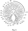
figure 3 est une vue schématique par en dessous d'un support rotatif d'articles optiques et d'un cache de répartition pour le contrôle du dépôt, - la
figure 4 est un schéma simplifié montrant un article optique caché par une partie de cache, - la
figure 5 est un schéma simplifié montrant une pluralité d'articles optiques avec une portion de cache, - la
figure 6 est un schéma similaire à celle de lafigure 4 d'un article optique ayant subi un traitement, et - Sur toutes les figures, les éléments identiques portent les mêmes numéros de référence. Une référence sous forme de numéro désigne un élément en général ou tous les éléments identiques. Quand le numéro de référence de l'élément est suivi d'une lettre avec ou sans prime, on désigne un élément particulier qui est distinct d'un élément ayant le même numéro de référence mais qui est suivi d'une lettre différente avec ou sans prime.
- On va maintenant décrire un exemple d'un mode de réalisation en référence aux figures.
- Les réalisations suivantes sont des exemples. Bien que la description se réfère à un ou plusieurs modes de réalisation, ceci ne signifie pas nécessairement que chaque référence concerne le même mode de réalisation, ou que les caractéristiques s'appliquent seulement à un seul mode de réalisation. De simples caractéristiques de différents modes de réalisation peuvent également être combinées ou interchangées pour fournir d'autres réalisations.
- La
figure 1 montre un article optique 10 sur lequel un quelconque traitement doit être appliqué. - Cet article optique 10 peut être préférentiellement un article ophtalmique, et en particulier, un insert ou palet de contour, une plaquette, un verre semi-fini, une lentille, correctrice ou non, qui peut être utilisée comme un verre de lunette, par exemple pour des lunettes, en particulier des lunettes de soleil ou des masques ou analogues. Cet article est notamment réalisé en verre minéral ou en matière plastique. L'article optique 10 peut être réalisé en une ou plusieurs couches formant un ensemble.
- Le traitement à appliquer sur l'article optique 10 peut être un traitement antireflet et/ou un traitement de durcissement, et/ou un traitement d'application d'une couleur.
- La
figure 2 montre de façon schématique une installation 20 de dépôt par évaporation d'un revêtement sur un ensemble d'articles optiques 10. - Cette installation 20 comprend une enceinte de traitement 21 et une source 22 émettrice de molécules d'un matériau à déposer sur les articles optiques 10 selon un cône d'évaporation 24.
- L'enceinte de traitement 21 peut être fermée hermétiquement et est reliée à une unité de vide (non représentée), par exemple une pompe à vide, pour baisser la pression à l'intérieur de l'enceinte de traitement 21 à une pression adaptée pour le traitement à appliquer, typiquement par exemple de l'ordre de 3.10-5 mbar.
- La source émettrice 22 est par exemple constituée par un support sur lequel est disposé le matériau à évaporer, par exemple un creuset ou une platine, et, pour son évaporation, le matériau est par exemple soumis à un échauffement par effet Joule, à un bombardement électronique, ou à un effet de pulvérisation cathodique.
- Le cône d'évaporation 24 n'est pas uniforme et possède dans le centre une densité de molécules évaporées plus importante que sur la périphérie ce qui est indiqué sur la
figure 2 par une couleur grise du cône d'évaporation 24 plus foncée au niveau du centre par rapport à la périphérie. Bien entendu, la densité diminue en réalité progressivement depuis le centre vers la périphérie. - Au-dessus de la source émettrice 22 est disposé un support rotatif 26 des articles optiques 10.
- A cet effet, le support rotatif 26 comporte des logements individuels 28 des articles optiques 10.
- Comme on peut mieux le voir sur la
figure 3 montrant une vue par en-dessous du support rotatif 26, les logements individuels 28 sont disposés par exemple sur des pistes concentriques 30 matérialisées sur lafigure 3 par des cercles en traits. - Dans le présent exemple, le support rotatif 26 comporte quatre pistes concentriques référencées individuellement 30A, 30B, 30C et 30D avec des logements individuels 28.
- Bien entendu, on peut prévoir plus ou moins de pistes concentriques 30 en fonction de la taille de l'installation 20 et en particulier de l'enceinte de traitement 21.
- Par ailleurs, sur le support rotatif 26, les pistes concentriques ne sont généralement pas matérialisées. Une piste 30 est par exemple définie par l'ensemble des logements individuels 28 disposés à la même distance du centre du support rotatif 26.
- On comprend qu'en rotation du support 26, chacun des logements individuels 28 réalise des tours de révolution.
- Le support rotatif 26 possède par exemple une forme concave ou plus spécifiquement en forme de calotte sphérique de sorte que les logements individuels 28 des articles optiques 10 sont disposés à égale distance de la source émettrice 22.
- Le support rotatif 26 peut tourner autour d'un axe A qui correspond à l'axe de symétrie du support rotatif et passe par le centre de celui-ci.
- L'installation 20 comporte de plus un cache 32 de répartition pour le contrôle du dépôt par évaporation d'un revêtement sur des articles optiques 10. Ce cache 32 est disposé sur le trajet d'une partie des molécules émises par la source émettrice 22 en direction du support rotatif 26 des articles optiques 10.
- Comme la
figure 3 peut être assimilée à une vue du support rotatif 26 depuis la source 22, on voit que le cache 32 s'interpose pour une partie des molécules émises par la source 22. - Plus précisément, le cache 32 comporte au moins un bras 34, dans le présent cas huit bras individuellement référencés individuellement 34A, 34A', 34B, 34B', 34C, 34C' et 34D, 34D'. Dans ce mode de réalisation particulier, les bras ont une forme générale courbe.
- Ces bras courbes 34 s'étendent chacun le long d'une piste associée 30 et sont disposés de façon centrée en face de celle-ci.
- Ainsi, les bras courbes 34A, 34A' sont associés à la piste 30A, les bras courbes 34B, 34B' à la piste 30B, les bras courbes 34C, 34C' à la piste 30C et les bras courbes 34D, 34D' à la piste 30D.
- Le cache 32 comporte donc deux bras courbes 34 pour chaque piste 30 du support rotatif 26 qui sont disposés symétriquement par rapport à un axe radial de maintien 36 (voir
figure 3 ). - Le rayon de courbure de chaque bras 34 suit celui de la piste associée 30.
- La largeur de chaque bras courbe 34 perpendiculaire à la piste associée 30 est configurée de manière que l'empreinte projetée du bras courbe 34 sur les logements individuels 28 et donc sur les articles optiques 10 maintenus dans ces logements individuels 28 de la piste associée 30 possède une largeur perpendiculaire à la piste associée 30 qui est inférieure à la largeur des articles optiques 10 et des logements individuels 28 portés par le support rotatif 26.
- L'empreinte projetée peut être assimilée à l'ombre qui serait portée sur le support rotatif 26 par le cache 32 si la source émettrice 22 était une source de lumière. On comprend aisément que si on rapprochait le cache 32 de la source émettrice 22, du fait du cône d'émission 24, il faudrait réduire la taille du cache 32 pour obtenir les mêmes effets.
- Pour être le plus précis possible dans le dépôt des revêtements, on essaie de placer le cache 32 le plus près possible du support rotatif 26, typiquement à une dizaine de cm.
- Ceci est bien visible sur la
figure 3 , mais illustré plus en détail sur lesfigures 4 et 5 . - En effet, les
figures 4 et 5 montrent de façon schématique une vue du bras courbe 34 depuis la source émettrice 22. - Alors que sur la
figure 3 sont montrés les logements individuels 28, et sur lesfigures 4 et 5 est représenté un article optique 10. Le contour de l'article optique 10 desfigures 4 et 5 est sensiblement le même que le contour de chaque logement individuel 28 pour pouvoir maintenir ces articles optiques 10. Ainsi, lesfigures 4 et 5 peuvent également s'interpréter par rapport aux logements individuels 28 des articles optiques 10. - Lorsque par la rotation du support rotatif 26, l'article optique 10 dans son logement individuel 28 passe derrière un bras courbe 34 du cache 32, seules des portions latérales ou des bords 12 et 14 sont exposées aux molécules émises par la source émettrice 22.
- Ainsi, le ou les bras courbes 34 empêchent le dépôt de molécules dans une zone partielle 16 comprenant le centre du logement individuel 28. Cette zone partielle 16 correspond dans le cas présent à une portion centrale (voir
figure 5 ) des articles optiques 10 et permettent le dépôt de molécules dans les deux portions latérales 12 et 14 des articles optiques 10, ces portions latérales 12 et 14 étant disposées de part et d'autre par rapport à la piste 30 associée. En effet, le centre de l'article optique 10 est à une distance différente de la source émettrice 22 par rapport au bord de l'article optique 10. Dans le cas d'un article optique 10 ayant une courbure ou sphéricité importante, le centre de l'article optique 10 est plus proche de la source émettrice 22 que les bords périphériques. Ainsi, sur un tour de révolution, l'article optique 10 recevrait plus de molécules qui se déposent dans sa partie centrale que sur les bords périphériques. Ceci est donc corrigé par le ou les bras courbes 34 car quand l'article optique 10 est caché par le ou les bras courbes 34, le centre ne reçoit pas de molécules tandis que les bords périphériques en reçoivent toujours. Ainsi, sur un tour de révolution, lorsqu'il n'y a pas de cache devant l'article optique 10, des molécules se déposent sur l'ensemble de l'article optique 10, mais avec une densité plus importante au centre de celui-ci, la zone partielle 16 comprenant le centre du logement individuel 28 (plus proche de la source émettrice 22), que les portions latérales 12 et 14. Lorsque l'article optique 10 est caché par le ou les bras courbes 34, des molécules se déposent uniquement sur les parties latérales 12 et 14 et comblent donc le déficit de molécules déposées par rapport à la zone partielle 16 comprenant le centre de l'article optique 10. - La présence de ce ou ces bras 34 permet de pallier l'écart de distance entre le centre et les bords de l'article optique 10 entraînant un gradient de densité de molécules déposées et permettant ainsi d'assurer une meilleure uniformité du dépôt du revêtement sur l'ensemble de l'article optique 10 ayant une courbure ou une sphéricité importante.
- On comprend donc que le cache de répartition 32 est aménagé avec au moins un bras 34 disposé de manière à masquer une zone partielle 16 d'un logement individuel 28 sur une partie du tour de révolution, cette zone partielle 16 masquée comprenant le centre du logement individuel 28.
- La largueur LB des bras courbes 34 selon une direction perpendiculaire à la piste 30 est inférieure à la largeur LA des articles optiques 10 destinés à être portés par le support rotatif 26. La largeur LA des articles optiques est mesurée radialement par rapport au centre du support rotatif 26.
- Plus spécifiquement, la largeur LB perpendiculaire à la piste associée 30 de l'empreinte projetée du bras courbe 34 sur les articles optiques de la piste associée 30 est comprise entre 60% et 95%, notamment comprise entre 80% et 90% et plus particulièrement d'environ 85% de la largeur LA des articles optiques portés par le support rotatif.
- La longueur des paires de bras courbes 34, en tenant compte d'une partie centrale du cache, couvre angulairement un secteur de cercle compris entre 60° et 160°, notamment entre 80° et 140°. Ainsi, lors d'une rotation du support mobile 26, en tenant compte d'une largeur centrale du cache, la partie centrale 16 de l'article optique 10 est seulement exposée aux molécules émises par la source émettrice 22 sur une course angulaire comprise entre 200° et 300°, notamment entre 220° et 280°. Il en résulte aussi que la longueur des bras courbes 34 augmente avec l'éloignement des pistes 30 associées concentriques par rapport à l'axe de rotation A du support rotatif 26.
- Dans cette même configuration, les portions latérales 12 et 16 de l'article optique 10 sont exposées aux molécules émises par la source émettrice 22 sur une course angulaire supérieure à comprise entre 250° et 350°, par exemple entre 280° et 350°, par exemple environ 340°.
- Selon un mode de réalisation non représenté, le cache 32 peut comporter un unique bras 34 par piste 30 ou deux bras par piste 30. La longueur cumulée du ou des bras 34 d'une piste 30 est avantageusement choisie en fonction d'une différence de hauteur entre le bord et le centre d'un article optique 10 prévu pour être placé dans une des logements individuels 28. En particulier, ladite longueur peut être choisie de façon à couvrir, pour une piste 30, un secteur de cercle choisi en fonction de ladite hauteur. Notamment, ladite hauteur peut être une hauteur moyenne ou médiane des articles optiques 10 destinés à être traités dans ladite installation 20.
- De façon plus précise, ladite longueur peut être choisie en fonction de l'impact de la différence de hauteur sur la différence de densité de flux de matière à déposer arrivant respectivement au bord et au centre de l'article optique 10.
- Pour encore mieux uniformiser le dépôt, les extrémités 38 (38A, 38A', 38B, 38B', 38C, 38C' et 38D, 38D') des bras courbes 34 possèdent une forme arrondie, dont le rayon de courbure des extrémités arrondies correspond au rayon de courbure de l'article optique 10 devant recevoir le revêtement.
- Alors que les bras courbes 34 permettent de mieux homogénéiser le dépôt sur la surface des articles optiques 10 du fait de la courbure ou convexité de ces articles 10, le cache 32 comporte en outre une portion centrale 40 de forme générale, ici en ellipse, configurée pour compenser une inhomogénéité du cône d'évaporation 24 entre les différentes pistes 30 de logements 28 d'articles optiques 10.
- Alternativement cette portion centrale peut être absente, ou être sous la forme d'un triangle, d'un losange, d'un trapèze ou de toute autre forme appropriée.
- Cette portion centrale 40 est fixée de manière centrale sur l'axe de maintien radial 36.
- Comme on le voit sur la
figure 3 , le cache 32 comporte donc la partie centrale 40 et pour chaque piste 30A, 30B, 30C et 30D de logements un premier 34A, 34B, 34C, et 34D et un second 34A', 34B', 34C' et 34D' bras courbe prolongeant la portion centrale 40 symétriquement par rapport au grand axe d'ellipse disposé de façon radiale par rapport à l'axe de rotation A du support rotatif 26. - Selon une variante non représentée, on peut aussi utiliser deux caches de répartition distincts, un premier cache de répartition avec les bras courbes pour compenser la courbure des articles optiques 10 et un second cache de répartition de forme calibrée pour compenser l'inhomogénéité du cône d'émission 24, disposé par exemple dans un autre secteur du support rotatif 26, en particulier en vis-à-vis.
- Enfin, dans un mode de réalisation les extrémités 38 arrondies des bras courbes 34 s'inscrivent dans une forme de semi-ellipse correspondant au tracé de la portion centrale 40 en forme d'ellipse. C'est-à-dire, si on reliait par une courbe imaginaire les extrémités 38A, 38B, 38C, et 38D, on obtient une forme de semi-ellipse qui est sensiblement identique à la forme en ellipse de la portion centrale 40 du même côté de l'axe de maintien 36 mais seulement décalé angulairement. De même, si on reliait par une courbe imaginaire les extrémités 38A', 38B', 38C', et 38D,' on obtient une forme de semi-ellipse qui est sensiblement identique à la forme en ellipse de la portion centrale 40 du même côté de l'axe de maintien 36 mais seulement décalé angulairement.
- Une telle forme de semi-ellipse est conçue pour compenser une variation radiale de vitesse de dépôt de matière sur le support rotatif 26, pouvant être due à un écart de la forme du support rotatif 26 par rapport à une portion de sphère centrée sur la source émettrice 22 ou pouvant être dus à une inhomogénéité radiale de distribution de la matière émise par ladite source émettrice.
- Dans un autre mode de réalisation, les extrémités 38 arrondies des bras courbes 34 s'inscrivent dans une telle forme de semi-ellipse sans pour autant que la portion centrale 40 ait une forme en ellipse.
- La
figure 6 montre un schéma similaire à lafigure 4 d'un article optique 10 sur lequel un revêtement a été appliqué comme expliqué ci-dessus. On comprend donc aussi que le revêtement a pu être homogénéisé dans les portions latérales 12 et 14 et centrale 16. - Cependant, dans les portions 18A et 18B, l'homogénéisation du revêtement appliqué est moins bonne que pour les portions 12 et 14 par rapport à la portion centrale 16.
- En fonction des exigences souhaitées, on peut couper l'article optique 10 selon les lignes en traits 44 pour obtenir par exemple une lentille ou un verre optique de forme générale rectangulaire.
- Ainsi, l'installation selon l'invention permet de déposer de façon très homogène des revêtements sur un article optique 10, au moins selon une bande perpendiculaire à la position de l'article 10 dans le support rotatif 26 grâce au cache 32 avec des bras courbes 34 afin de compenser en particulier l'écart de répartition du revêtement qui est dû à la courbure / sphéricité de l'article optique 10.
Claims (12)
- Installation (20) de dépôt par évaporation d'un revêtement sur des articles optiques (10), comportant- une source émettrice (22) de molécules d'un matériau à déposer sur les articles optiques (10), les molécules étant émises selon un cône d'évaporation,- un support rotatif (26) d'articles optiques (10) comportant des logements individuels (28) destinés à recevoir les articles optiques (10) et réalisant en cours de rotation du support rotatif (26) des tours de révolution, les logements individuels (28) d'articles optiques (10) étant disposés en pistes concentriques (30), et- un cache de répartition (32) disposé sur le trajet d'une partie des molécules émises par ladite source émettrice (22) en direction du support rotatif (26) d'articles optiques (10),dans laquelle le cache de répartition (32) est aménagé avec au moins un bras courbe (34) s'étendant le long d'une piste (30) associée et disposé de manière à masquer une zone partielle (16) d'un logement individuel (28) sur une partie du tour de révolution, cette zone partielle (16) masquée comprenant le centre du logement individuel (28), le au moins un bras courbe (34) étant disposé de façon centrée en face de la piste concentrique (30) et la largeur de chaque bras courbe (34) perpendiculaire à la piste associée (30) est configurée de manière que l'empreinte projetée du bras courbe (34) sur les logements individuels (28) de la piste associée (30) possède une largeur perpendiculaire à la piste associée (30) qui est inférieure à la largeur des logements individuels (28)
- Installation selon la revendication 1, dans laquelle le cache (32) comporte un bras (34) pour chaque piste (30) du support rotatif (26).
- Installation selon l'une quelconque des revendications 1 à 2, dans laquelle la largeur (LB) perpendiculaire à la piste associée (30) de l'empreinte projetée du bras (34) sur les articles optiques (10) de la piste associée (30) est comprise entre 60% et 95%, notamment comprise entre 80% et 90% et plus particulièrement 85% de la largeur des articles optiques (10) portés par le support rotatif (26).
- Installation selon l'une quelconque des revendications 1 à 3, dans laquelle chaque bras (34) possède une extrémité arrondie (38).
- Installation selon la revendication 4, dans laquelle le rayon de courbure des extrémités arrondies (38) correspond au rayon de courbure de l'article optique (10) devant recevoir le revêtement.
- Installation selon l'une quelconque des revendications 1 à 5, dans laquelle le cache (32) comporte une portion centrale (40) configurée pour compenser une inhomogénéité du cône d'évaporation (24) entre les différentes pistes (30) de logements (28) d'articles optiques.
- Installation selon la revendication 6, dans laquelle elle comprend pour chaque piste (30) de logements (28) un premier et un second bras (34) prolongeant la portion centrale (40) symétriquement de part et d'autre de la portion centrale (40).
- Installation selon la revendication 6 ou 7, dans laquelle la portion centrale (40) présente une forme elliptique ou trapézoïdale.
- Installation selon l'une quelconque des revendications 1 à 8, dans laquelle la longueur des bras (34) augmente avec l'éloignement des pistes associées (30) concentriques par rapport à l'axe de rotation (A) du support rotatif (26).
- Installation selon la revendication 6 ou 7, dans laquelle la longueur des paires de bras courbes (34), en tenant compte d'une portion centrale (40), couvre angulairement un secteur de cercle compris entre 60° et 160°, notamment entre 80° et 140°.
- Installation selon l'une quelconque des revendications 6 à 10, dans laquelle les extrémités (38) des bras (34) s'inscrivent dans une forme correspondant au tracé de la portion centrale (40).
- Installation selon l'une quelconque des revendications 1 à 11, dans laquelle le support rotatif (26) possède une forme concave de sorte que les logements (28) d'articles optiques sont disposés à égale distance de la source émettrice (22).
Applications Claiming Priority (2)
| Application Number | Priority Date | Filing Date | Title |
|---|---|---|---|
| FR1660904A FR3058424B1 (fr) | 2016-11-10 | 2016-11-10 | Installation de depot par evaporation d'un revetement sur des articles |
| PCT/EP2017/078471 WO2018087090A1 (fr) | 2016-11-10 | 2017-11-07 | Installation de dépôt par évaporation d'un revêtement sur des articles optiques |
Publications (2)
| Publication Number | Publication Date |
|---|---|
| EP3538683A1 EP3538683A1 (fr) | 2019-09-18 |
| EP3538683B1 true EP3538683B1 (fr) | 2022-08-17 |
Family
ID=57583368
Family Applications (1)
| Application Number | Title | Priority Date | Filing Date |
|---|---|---|---|
| EP17797610.7A Active EP3538683B1 (fr) | 2016-11-10 | 2017-11-07 | Installation de dépôt par évaporation d'un revêtement sur des articles optiques |
Country Status (5)
| Country | Link |
|---|---|
| US (1) | US11821072B2 (fr) |
| EP (1) | EP3538683B1 (fr) |
| CN (1) | CN109963962B (fr) |
| FR (1) | FR3058424B1 (fr) |
| WO (1) | WO2018087090A1 (fr) |
Families Citing this family (4)
| Publication number | Priority date | Publication date | Assignee | Title |
|---|---|---|---|---|
| WO2021123858A1 (fr) | 2019-12-19 | 2021-06-24 | Essilor International | Article optique adapté à un écran |
| KR102597694B1 (ko) * | 2021-06-23 | 2023-11-03 | 주식회사 아이브이티코리아 | 렌즈 코팅 장치 및 그 제어 방법 |
| CN117735848A (zh) * | 2022-09-20 | 2024-03-22 | 苹果公司 | 用于弯曲表面的涂层 |
| CN117144315A (zh) * | 2023-08-14 | 2023-12-01 | 广东银度光能科技有限公司 | 磁控溅射设备 |
Citations (1)
| Publication number | Priority date | Publication date | Assignee | Title |
|---|---|---|---|---|
| DE10234855A1 (de) * | 2002-07-31 | 2004-02-12 | Fraunhofer-Gesellschaft zur Förderung der angewandten Forschung e.V. | Einrichtung zur Einstellung einer vorgegebenen Schichtdickenverteilung bei Vakuumbeschichtungsprozessen auf bewegten Substraten |
Family Cites Families (31)
| Publication number | Priority date | Publication date | Assignee | Title |
|---|---|---|---|---|
| US3904503A (en) * | 1974-05-31 | 1975-09-09 | Western Electric Co | Depositing material on a substrate using a shield |
| CH650028A5 (de) | 1980-09-26 | 1985-06-28 | Balzers Hochvakuum | Anordnung zum gleichfoermigen beschichten von rotationsflaechen durch bedampfen im hochvakuum. |
| CH652754A5 (de) * | 1981-03-13 | 1985-11-29 | Balzers Hochvakuum | Anordnung zum beschichten von substraten in einer vakuumbeschichtungsanlage. |
| CN86205741U (zh) | 1986-08-16 | 1987-07-15 | 北京市有色金属研究总院 | 物理气相沉积用的涂层装置 |
| US5859937A (en) * | 1997-04-04 | 1999-01-12 | Neomecs Incorporated | Minimally invasive sensor |
| CN1130575C (zh) | 1997-05-16 | 2003-12-10 | 保谷株式会社 | 具有抗反射膜的塑料光学器件以及用来使抗反射膜的厚度均一的机构 |
| FR2775298B1 (fr) | 1998-02-24 | 2000-05-05 | Essilor Int | Cache de repartition pour le controle du depot par evaporation d'un quelconque revetement sur un quelconque substrat, enceinte de traitement mettant en oeuvre un tel cache de repartition, et procede correspondant |
| US7062348B1 (en) * | 2000-07-13 | 2006-06-13 | The Extreme Ultaviolet Lithography Llc | Dynamic mask for producing uniform or graded-thickness thin films |
| US6447653B1 (en) * | 2000-10-11 | 2002-09-10 | Litton Systems Inc. | Method of shaping a flux mask and process of sputtering with the shaped flux mask |
| US6419803B1 (en) * | 2001-03-16 | 2002-07-16 | 4Wave, Inc. | System and method for making thin-film structures using a stepped profile mask |
| US6716322B1 (en) * | 2001-04-19 | 2004-04-06 | Veeco Instruments Inc. | Method and apparatus for controlling film profiles on topographic features |
| US20030180462A1 (en) * | 2002-03-19 | 2003-09-25 | Temescal, A Unit Of The Boc Group, Inc. | Planetary lift-off vapor deposition system |
| TW593725B (en) * | 2002-04-30 | 2004-06-21 | Prodisc Technology Inc | Coating device and method |
| DE10324928A1 (de) * | 2003-06-03 | 2005-07-14 | Leybold Optics Gmbh | Vakuumbeschichtungsanlage |
| EP1491653A3 (fr) * | 2003-06-13 | 2005-06-15 | Pioneer Corporation | Méthodes et dispositifs pour dépôt par vaporisation |
| US8039052B2 (en) * | 2007-09-06 | 2011-10-18 | Intermolecular, Inc. | Multi-region processing system and heads |
| CN101407908B (zh) * | 2007-10-09 | 2010-06-09 | 鸿富锦精密工业(深圳)有限公司 | 补正板 |
| US8347814B2 (en) * | 2008-01-22 | 2013-01-08 | Raytheon Canada Limited | Method and apparatus for coating a curved surface |
| US20090258151A1 (en) * | 2008-04-10 | 2009-10-15 | Raytheon Company | Method and Apparatus for Coating Curved Surfaces |
| US8398776B2 (en) * | 2008-05-12 | 2013-03-19 | Raytheon Canada Limited | Method and apparatus for supporting workpieces in a coating apparatus |
| DE102009044957A1 (de) | 2008-09-30 | 2010-04-08 | Carl Zeiss Smt Ag | Stützelemente für ein optisches Element |
| US20100189929A1 (en) * | 2009-01-28 | 2010-07-29 | Neal James W | Coating device and deposition apparatus |
| MY160386A (en) * | 2009-04-28 | 2017-03-15 | Ferrotec (Usa) Corp | Lift-off deposition system featuring a density optimized hula substrate holder in a conical deposition chamber |
| TW201200614A (en) * | 2010-06-29 | 2012-01-01 | Hon Hai Prec Ind Co Ltd | Coating device |
| EP2761253B1 (fr) * | 2011-09-29 | 2015-09-09 | SI-Ware Systems | Gyroscope laser annulaire à base de mems à blocage réduit |
| TW201317372A (zh) * | 2011-10-31 | 2013-05-01 | Hon Hai Prec Ind Co Ltd | 鍍膜修正板及鍍膜裝置 |
| TW201337025A (zh) * | 2012-03-01 | 2013-09-16 | Hon Hai Prec Ind Co Ltd | 鍍膜修正板 |
| US9555441B2 (en) * | 2013-05-03 | 2017-01-31 | Abb Schweiz Ag | Dynamic synchronized masking and coating |
| KR20160008307A (ko) * | 2014-07-14 | 2016-01-22 | 주식회사 동진쎄미켐 | 광학투명레진을 이용한 디스플레이 모듈 제조방법 |
| JP6019310B1 (ja) * | 2015-04-16 | 2016-11-02 | ナルックス株式会社 | 蒸着装置及び蒸着装置による成膜工程を含む製造方法 |
| EP3296423B1 (fr) * | 2016-09-16 | 2019-01-30 | Satisloh AG | Appareil pour le revêtement sous vide |
-
2016
- 2016-11-10 FR FR1660904A patent/FR3058424B1/fr not_active Expired - Fee Related
-
2017
- 2017-11-07 EP EP17797610.7A patent/EP3538683B1/fr active Active
- 2017-11-07 US US16/347,957 patent/US11821072B2/en active Active
- 2017-11-07 CN CN201780068146.1A patent/CN109963962B/zh active Active
- 2017-11-07 WO PCT/EP2017/078471 patent/WO2018087090A1/fr not_active Ceased
Patent Citations (1)
| Publication number | Priority date | Publication date | Assignee | Title |
|---|---|---|---|---|
| DE10234855A1 (de) * | 2002-07-31 | 2004-02-12 | Fraunhofer-Gesellschaft zur Förderung der angewandten Forschung e.V. | Einrichtung zur Einstellung einer vorgegebenen Schichtdickenverteilung bei Vakuumbeschichtungsprozessen auf bewegten Substraten |
Also Published As
| Publication number | Publication date |
|---|---|
| WO2018087090A1 (fr) | 2018-05-17 |
| US11821072B2 (en) | 2023-11-21 |
| US20190284679A1 (en) | 2019-09-19 |
| CN109963962A (zh) | 2019-07-02 |
| FR3058424A1 (fr) | 2018-05-11 |
| FR3058424B1 (fr) | 2022-06-10 |
| CN109963962B (zh) | 2021-09-17 |
| EP3538683A1 (fr) | 2019-09-18 |
Similar Documents
| Publication | Publication Date | Title |
|---|---|---|
| EP3538683A1 (fr) | Installation de dépôt par évaporation d'un revêtement sur des articles optiques | |
| JP5840448B2 (ja) | 反射防止膜及び反射防止膜の製造方法 | |
| EP2217962B1 (fr) | Pastille courbe de modification d'une puissance d'un composant optique | |
| EP2024765A1 (fr) | Pastille de modification d'une puissance d'un composant optique | |
| JP2012189846A (ja) | 反射防止光学素子及び反射防止光学素子の製造方法 | |
| EP1109946B1 (fr) | Support pour lentille optique, et son procede de mise en oeuvre | |
| FR2907699A1 (fr) | Patin de polissage ayant des rainures espacees de maniere irreguliere | |
| EP1792224A1 (fr) | Procede de fabrication d'une lentille ophtalmique destinee a la realisation d'un afficheur optique | |
| FR2907922A1 (fr) | Procede de fabrication d'une serie de verres ophtalmiques et feuille de film utilisee dans un tel procede. | |
| EP0439394A2 (fr) | Procédé pour la fabrication d'une lentille optique artificielle, et lentille optique artificielle correspondante | |
| EP1957274A2 (fr) | Procede de transfert d'un motif micronique sur un article optique et article optique ainsi obtenu | |
| EP3320390B1 (fr) | Dispositif ophtalmique à cellule à variation de transmission perfectionnée | |
| FR2732362A1 (fr) | Poste pour l'application de revetement sur des substrats courbes, notamment des lentilles optiques ou ophtalmiques | |
| CA2341608C (fr) | Procede pour le depot sous vide d'un substrat courbe | |
| CA2321886C (fr) | Cache de repartition pour depot par evaporation sous vide | |
| FR2918463A1 (fr) | Film transparent comprenant un film de base et un revetement | |
| FR2904697A1 (fr) | Procede pour appliquer sur une face d'une lentille un revetement et appareil pour la mise en oeuvre d'un tel procede | |
| FR2569863A1 (fr) | Vitrage a portion de surface semi-reflechissante, son procede de fabrication et son application comme pare-brise | |
| EP4127786B1 (fr) | Procédé de traitement d'un article optique miroité | |
| JP2017167303A (ja) | 光学素子及び光学薄膜の成膜方法 | |
| FR2895524A1 (fr) | Lentille optique et procede mettant en oeuvre des moyens d'indexation angulaire | |
| EP0784223A1 (fr) | Oculaire pour lunettes et son procédé et dipositif de fabrication | |
| FR2990369A1 (fr) | Procede de detourage d'une lentille ophtalmique multicouche | |
| CH718004B1 (fr) | Réhaut de montre, de montre-bracelet et procédé de fabrication d'un réhaut de montre. | |
| FR2581793A1 (fr) | Procede et dispositif de fabrication de composants electroniques ou optoelectroniques avec depot par evaporation sous vide |
Legal Events
| Date | Code | Title | Description |
|---|---|---|---|
| STAA | Information on the status of an ep patent application or granted ep patent |
Free format text: STATUS: UNKNOWN |
|
| STAA | Information on the status of an ep patent application or granted ep patent |
Free format text: STATUS: THE INTERNATIONAL PUBLICATION HAS BEEN MADE |
|
| PUAI | Public reference made under article 153(3) epc to a published international application that has entered the european phase |
Free format text: ORIGINAL CODE: 0009012 |
|
| STAA | Information on the status of an ep patent application or granted ep patent |
Free format text: STATUS: REQUEST FOR EXAMINATION WAS MADE |
|
| 17P | Request for examination filed |
Effective date: 20190516 |
|
| AK | Designated contracting states |
Kind code of ref document: A1 Designated state(s): AL AT BE BG CH CY CZ DE DK EE ES FI FR GB GR HR HU IE IS IT LI LT LU LV MC MK MT NL NO PL PT RO RS SE SI SK SM TR |
|
| AX | Request for extension of the european patent |
Extension state: BA ME |
|
| DAV | Request for validation of the european patent (deleted) | ||
| DAX | Request for extension of the european patent (deleted) | ||
| STAA | Information on the status of an ep patent application or granted ep patent |
Free format text: STATUS: EXAMINATION IS IN PROGRESS |
|
| 17Q | First examination report despatched |
Effective date: 20200312 |
|
| RAP3 | Party data changed (applicant data changed or rights of an application transferred) |
Owner name: BNL EUROLENS |
|
| GRAP | Despatch of communication of intention to grant a patent |
Free format text: ORIGINAL CODE: EPIDOSNIGR1 |
|
| STAA | Information on the status of an ep patent application or granted ep patent |
Free format text: STATUS: GRANT OF PATENT IS INTENDED |
|
| INTG | Intention to grant announced |
Effective date: 20220407 |
|
| GRAS | Grant fee paid |
Free format text: ORIGINAL CODE: EPIDOSNIGR3 |
|
| GRAA | (expected) grant |
Free format text: ORIGINAL CODE: 0009210 |
|
| STAA | Information on the status of an ep patent application or granted ep patent |
Free format text: STATUS: THE PATENT HAS BEEN GRANTED |
|
| AK | Designated contracting states |
Kind code of ref document: B1 Designated state(s): AL AT BE BG CH CY CZ DE DK EE ES FI FR GB GR HR HU IE IS IT LI LT LU LV MC MK MT NL NO PL PT RO RS SE SI SK SM TR |
|
| REG | Reference to a national code |
Ref country code: CH Ref legal event code: EP |
|
| REG | Reference to a national code |
Ref country code: DE Ref legal event code: R096 Ref document number: 602017060790 Country of ref document: DE |
|
| REG | Reference to a national code |
Ref country code: IE Ref legal event code: FG4D Free format text: LANGUAGE OF EP DOCUMENT: FRENCH |
|
| REG | Reference to a national code |
Ref country code: AT Ref legal event code: REF Ref document number: 1512219 Country of ref document: AT Kind code of ref document: T Effective date: 20220915 |
|
| REG | Reference to a national code |
Ref country code: NL Ref legal event code: MP Effective date: 20220817 |
|
| REG | Reference to a national code |
Ref country code: LT Ref legal event code: MG9D |
|
| PG25 | Lapsed in a contracting state [announced via postgrant information from national office to epo] |
Ref country code: SE Free format text: LAPSE BECAUSE OF FAILURE TO SUBMIT A TRANSLATION OF THE DESCRIPTION OR TO PAY THE FEE WITHIN THE PRESCRIBED TIME-LIMIT Effective date: 20220817 Ref country code: RS Free format text: LAPSE BECAUSE OF FAILURE TO SUBMIT A TRANSLATION OF THE DESCRIPTION OR TO PAY THE FEE WITHIN THE PRESCRIBED TIME-LIMIT Effective date: 20220817 Ref country code: PT Free format text: LAPSE BECAUSE OF FAILURE TO SUBMIT A TRANSLATION OF THE DESCRIPTION OR TO PAY THE FEE WITHIN THE PRESCRIBED TIME-LIMIT Effective date: 20221219 Ref country code: NO Free format text: LAPSE BECAUSE OF FAILURE TO SUBMIT A TRANSLATION OF THE DESCRIPTION OR TO PAY THE FEE WITHIN THE PRESCRIBED TIME-LIMIT Effective date: 20221117 Ref country code: NL Free format text: LAPSE BECAUSE OF FAILURE TO SUBMIT A TRANSLATION OF THE DESCRIPTION OR TO PAY THE FEE WITHIN THE PRESCRIBED TIME-LIMIT Effective date: 20220817 Ref country code: LV Free format text: LAPSE BECAUSE OF FAILURE TO SUBMIT A TRANSLATION OF THE DESCRIPTION OR TO PAY THE FEE WITHIN THE PRESCRIBED TIME-LIMIT Effective date: 20220817 Ref country code: LT Free format text: LAPSE BECAUSE OF FAILURE TO SUBMIT A TRANSLATION OF THE DESCRIPTION OR TO PAY THE FEE WITHIN THE PRESCRIBED TIME-LIMIT Effective date: 20220817 Ref country code: FI Free format text: LAPSE BECAUSE OF FAILURE TO SUBMIT A TRANSLATION OF THE DESCRIPTION OR TO PAY THE FEE WITHIN THE PRESCRIBED TIME-LIMIT Effective date: 20220817 |
|
| REG | Reference to a national code |
Ref country code: AT Ref legal event code: MK05 Ref document number: 1512219 Country of ref document: AT Kind code of ref document: T Effective date: 20220817 |
|
| PG25 | Lapsed in a contracting state [announced via postgrant information from national office to epo] |
Ref country code: PL Free format text: LAPSE BECAUSE OF FAILURE TO SUBMIT A TRANSLATION OF THE DESCRIPTION OR TO PAY THE FEE WITHIN THE PRESCRIBED TIME-LIMIT Effective date: 20220817 Ref country code: IS Free format text: LAPSE BECAUSE OF FAILURE TO SUBMIT A TRANSLATION OF THE DESCRIPTION OR TO PAY THE FEE WITHIN THE PRESCRIBED TIME-LIMIT Effective date: 20221217 Ref country code: HR Free format text: LAPSE BECAUSE OF FAILURE TO SUBMIT A TRANSLATION OF THE DESCRIPTION OR TO PAY THE FEE WITHIN THE PRESCRIBED TIME-LIMIT Effective date: 20220817 Ref country code: GR Free format text: LAPSE BECAUSE OF FAILURE TO SUBMIT A TRANSLATION OF THE DESCRIPTION OR TO PAY THE FEE WITHIN THE PRESCRIBED TIME-LIMIT Effective date: 20221118 |
|
| PG25 | Lapsed in a contracting state [announced via postgrant information from national office to epo] |
Ref country code: SM Free format text: LAPSE BECAUSE OF FAILURE TO SUBMIT A TRANSLATION OF THE DESCRIPTION OR TO PAY THE FEE WITHIN THE PRESCRIBED TIME-LIMIT Effective date: 20220817 Ref country code: RO Free format text: LAPSE BECAUSE OF FAILURE TO SUBMIT A TRANSLATION OF THE DESCRIPTION OR TO PAY THE FEE WITHIN THE PRESCRIBED TIME-LIMIT Effective date: 20220817 Ref country code: ES Free format text: LAPSE BECAUSE OF FAILURE TO SUBMIT A TRANSLATION OF THE DESCRIPTION OR TO PAY THE FEE WITHIN THE PRESCRIBED TIME-LIMIT Effective date: 20220817 Ref country code: DK Free format text: LAPSE BECAUSE OF FAILURE TO SUBMIT A TRANSLATION OF THE DESCRIPTION OR TO PAY THE FEE WITHIN THE PRESCRIBED TIME-LIMIT Effective date: 20220817 Ref country code: CZ Free format text: LAPSE BECAUSE OF FAILURE TO SUBMIT A TRANSLATION OF THE DESCRIPTION OR TO PAY THE FEE WITHIN THE PRESCRIBED TIME-LIMIT Effective date: 20220817 Ref country code: AT Free format text: LAPSE BECAUSE OF FAILURE TO SUBMIT A TRANSLATION OF THE DESCRIPTION OR TO PAY THE FEE WITHIN THE PRESCRIBED TIME-LIMIT Effective date: 20220817 |
|
| REG | Reference to a national code |
Ref country code: DE Ref legal event code: R097 Ref document number: 602017060790 Country of ref document: DE |
|
| PG25 | Lapsed in a contracting state [announced via postgrant information from national office to epo] |
Ref country code: SK Free format text: LAPSE BECAUSE OF FAILURE TO SUBMIT A TRANSLATION OF THE DESCRIPTION OR TO PAY THE FEE WITHIN THE PRESCRIBED TIME-LIMIT Effective date: 20220817 Ref country code: EE Free format text: LAPSE BECAUSE OF FAILURE TO SUBMIT A TRANSLATION OF THE DESCRIPTION OR TO PAY THE FEE WITHIN THE PRESCRIBED TIME-LIMIT Effective date: 20220817 |
|
| PLBE | No opposition filed within time limit |
Free format text: ORIGINAL CODE: 0009261 |
|
| STAA | Information on the status of an ep patent application or granted ep patent |
Free format text: STATUS: NO OPPOSITION FILED WITHIN TIME LIMIT |
|
| PG25 | Lapsed in a contracting state [announced via postgrant information from national office to epo] |
Ref country code: MC Free format text: LAPSE BECAUSE OF FAILURE TO SUBMIT A TRANSLATION OF THE DESCRIPTION OR TO PAY THE FEE WITHIN THE PRESCRIBED TIME-LIMIT Effective date: 20220817 Ref country code: AL Free format text: LAPSE BECAUSE OF FAILURE TO SUBMIT A TRANSLATION OF THE DESCRIPTION OR TO PAY THE FEE WITHIN THE PRESCRIBED TIME-LIMIT Effective date: 20220817 |
|
| REG | Reference to a national code |
Ref country code: CH Ref legal event code: PL |
|
| P01 | Opt-out of the competence of the unified patent court (upc) registered |
Effective date: 20230525 |
|
| 26N | No opposition filed |
Effective date: 20230519 |
|
| REG | Reference to a national code |
Ref country code: BE Ref legal event code: MM Effective date: 20221130 |
|
| PG25 | Lapsed in a contracting state [announced via postgrant information from national office to epo] |
Ref country code: LI Free format text: LAPSE BECAUSE OF NON-PAYMENT OF DUE FEES Effective date: 20221130 Ref country code: CH Free format text: LAPSE BECAUSE OF NON-PAYMENT OF DUE FEES Effective date: 20221130 |
|
| PG25 | Lapsed in a contracting state [announced via postgrant information from national office to epo] |
Ref country code: SI Free format text: LAPSE BECAUSE OF FAILURE TO SUBMIT A TRANSLATION OF THE DESCRIPTION OR TO PAY THE FEE WITHIN THE PRESCRIBED TIME-LIMIT Effective date: 20220817 Ref country code: LU Free format text: LAPSE BECAUSE OF NON-PAYMENT OF DUE FEES Effective date: 20221107 |
|
| PG25 | Lapsed in a contracting state [announced via postgrant information from national office to epo] |
Ref country code: IE Free format text: LAPSE BECAUSE OF NON-PAYMENT OF DUE FEES Effective date: 20221107 |
|
| PG25 | Lapsed in a contracting state [announced via postgrant information from national office to epo] |
Ref country code: BE Free format text: LAPSE BECAUSE OF NON-PAYMENT OF DUE FEES Effective date: 20221130 |
|
| PG25 | Lapsed in a contracting state [announced via postgrant information from national office to epo] |
Ref country code: HU Free format text: LAPSE BECAUSE OF FAILURE TO SUBMIT A TRANSLATION OF THE DESCRIPTION OR TO PAY THE FEE WITHIN THE PRESCRIBED TIME-LIMIT; INVALID AB INITIO Effective date: 20171107 |
|
| PG25 | Lapsed in a contracting state [announced via postgrant information from national office to epo] |
Ref country code: CY Free format text: LAPSE BECAUSE OF FAILURE TO SUBMIT A TRANSLATION OF THE DESCRIPTION OR TO PAY THE FEE WITHIN THE PRESCRIBED TIME-LIMIT Effective date: 20220817 |
|
| PG25 | Lapsed in a contracting state [announced via postgrant information from national office to epo] |
Ref country code: MK Free format text: LAPSE BECAUSE OF FAILURE TO SUBMIT A TRANSLATION OF THE DESCRIPTION OR TO PAY THE FEE WITHIN THE PRESCRIBED TIME-LIMIT Effective date: 20220817 |
|
| PG25 | Lapsed in a contracting state [announced via postgrant information from national office to epo] |
Ref country code: TR Free format text: LAPSE BECAUSE OF FAILURE TO SUBMIT A TRANSLATION OF THE DESCRIPTION OR TO PAY THE FEE WITHIN THE PRESCRIBED TIME-LIMIT Effective date: 20220817 |
|
| PG25 | Lapsed in a contracting state [announced via postgrant information from national office to epo] |
Ref country code: BG Free format text: LAPSE BECAUSE OF FAILURE TO SUBMIT A TRANSLATION OF THE DESCRIPTION OR TO PAY THE FEE WITHIN THE PRESCRIBED TIME-LIMIT Effective date: 20220817 |
|
| PG25 | Lapsed in a contracting state [announced via postgrant information from national office to epo] |
Ref country code: MT Free format text: LAPSE BECAUSE OF FAILURE TO SUBMIT A TRANSLATION OF THE DESCRIPTION OR TO PAY THE FEE WITHIN THE PRESCRIBED TIME-LIMIT Effective date: 20220817 |
|
| PGFP | Annual fee paid to national office [announced via postgrant information from national office to epo] |
Ref country code: DE Payment date: 20251128 Year of fee payment: 9 |
|
| PGFP | Annual fee paid to national office [announced via postgrant information from national office to epo] |
Ref country code: GB Payment date: 20251127 Year of fee payment: 9 |
|
| PGFP | Annual fee paid to national office [announced via postgrant information from national office to epo] |
Ref country code: IT Payment date: 20251119 Year of fee payment: 9 |
|
| PGFP | Annual fee paid to national office [announced via postgrant information from national office to epo] |
Ref country code: FR Payment date: 20251125 Year of fee payment: 9 |