EP3538399B1 - Fahrzeugscheibe mit lichtleitkörper für einen sensor - Google Patents
Fahrzeugscheibe mit lichtleitkörper für einen sensor Download PDFInfo
- Publication number
- EP3538399B1 EP3538399B1 EP17804106.7A EP17804106A EP3538399B1 EP 3538399 B1 EP3538399 B1 EP 3538399B1 EP 17804106 A EP17804106 A EP 17804106A EP 3538399 B1 EP3538399 B1 EP 3538399B1
- Authority
- EP
- European Patent Office
- Prior art keywords
- light guide
- guide body
- glass pane
- glass
- vehicle window
- Prior art date
- Legal status (The legal status is an assumption and is not a legal conclusion. Google has not performed a legal analysis and makes no representation as to the accuracy of the status listed.)
- Not-in-force
Links
Images


Classifications
-
- B—PERFORMING OPERATIONS; TRANSPORTING
- B60—VEHICLES IN GENERAL
- B60Q—ARRANGEMENT OF SIGNALLING OR LIGHTING DEVICES, THE MOUNTING OR SUPPORTING THEREOF OR CIRCUITS THEREFOR, FOR VEHICLES IN GENERAL
- B60Q1/00—Arrangement of optical signalling or lighting devices, the mounting or supporting thereof or circuits therefor
- B60Q1/0011—Arrangement of optical signalling or lighting devices, the mounting or supporting thereof or circuits therefor with light guides for distributing the light between several lighting or signalling devices
-
- B—PERFORMING OPERATIONS; TRANSPORTING
- B60—VEHICLES IN GENERAL
- B60R—VEHICLES, VEHICLE FITTINGS, OR VEHICLE PARTS, NOT OTHERWISE PROVIDED FOR
- B60R11/00—Arrangements for holding or mounting articles, not otherwise provided for
- B60R11/04—Mounting of cameras operative during drive; Arrangement of controls thereof relative to the vehicle
-
- B—PERFORMING OPERATIONS; TRANSPORTING
- B23—MACHINE TOOLS; METAL-WORKING NOT OTHERWISE PROVIDED FOR
- B23K—SOLDERING OR UNSOLDERING; WELDING; CLADDING OR PLATING BY SOLDERING OR WELDING; CUTTING BY APPLYING HEAT LOCALLY, e.g. FLAME CUTTING; WORKING BY LASER BEAM
- B23K26/00—Working by laser beam, e.g. welding, cutting or boring
- B23K26/20—Bonding
- B23K26/21—Bonding by welding
-
- B—PERFORMING OPERATIONS; TRANSPORTING
- B32—LAYERED PRODUCTS
- B32B—LAYERED PRODUCTS, i.e. PRODUCTS BUILT-UP OF STRATA OF FLAT OR NON-FLAT, e.g. CELLULAR OR HONEYCOMB, FORM
- B32B17/00—Layered products essentially comprising sheet glass, or glass, slag, or like fibres
- B32B17/06—Layered products essentially comprising sheet glass, or glass, slag, or like fibres comprising glass as the main or only constituent of a layer, next to another layer of a specific material
- B32B17/10—Layered products essentially comprising sheet glass, or glass, slag, or like fibres comprising glass as the main or only constituent of a layer, next to another layer of a specific material of synthetic resin
- B32B17/10005—Layered products essentially comprising sheet glass, or glass, slag, or like fibres comprising glass as the main or only constituent of a layer, next to another layer of a specific material of synthetic resin laminated safety glass or glazing
- B32B17/10009—Layered products essentially comprising sheet glass, or glass, slag, or like fibres comprising glass as the main or only constituent of a layer, next to another layer of a specific material of synthetic resin laminated safety glass or glazing characterized by the number, the constitution or treatment of glass sheets
- B32B17/10036—Layered products essentially comprising sheet glass, or glass, slag, or like fibres comprising glass as the main or only constituent of a layer, next to another layer of a specific material of synthetic resin laminated safety glass or glazing characterized by the number, the constitution or treatment of glass sheets comprising two outer glass sheets
-
- B—PERFORMING OPERATIONS; TRANSPORTING
- B32—LAYERED PRODUCTS
- B32B—LAYERED PRODUCTS, i.e. PRODUCTS BUILT-UP OF STRATA OF FLAT OR NON-FLAT, e.g. CELLULAR OR HONEYCOMB, FORM
- B32B17/00—Layered products essentially comprising sheet glass, or glass, slag, or like fibres
- B32B17/06—Layered products essentially comprising sheet glass, or glass, slag, or like fibres comprising glass as the main or only constituent of a layer, next to another layer of a specific material
- B32B17/10—Layered products essentially comprising sheet glass, or glass, slag, or like fibres comprising glass as the main or only constituent of a layer, next to another layer of a specific material of synthetic resin
- B32B17/10005—Layered products essentially comprising sheet glass, or glass, slag, or like fibres comprising glass as the main or only constituent of a layer, next to another layer of a specific material of synthetic resin laminated safety glass or glazing
- B32B17/10165—Functional features of the laminated safety glass or glazing
-
- B—PERFORMING OPERATIONS; TRANSPORTING
- B60—VEHICLES IN GENERAL
- B60J—WINDOWS, WINDSCREENS, NON-FIXED ROOFS, DOORS, OR SIMILAR DEVICES FOR VEHICLES; REMOVABLE EXTERNAL PROTECTIVE COVERINGS SPECIALLY ADAPTED FOR VEHICLES
- B60J1/00—Windows; Windscreens; Accessories therefor
- B60J1/08—Windows; Windscreens; Accessories therefor arranged at vehicle sides
-
- B—PERFORMING OPERATIONS; TRANSPORTING
- B60—VEHICLES IN GENERAL
- B60J—WINDOWS, WINDSCREENS, NON-FIXED ROOFS, DOORS, OR SIMILAR DEVICES FOR VEHICLES; REMOVABLE EXTERNAL PROTECTIVE COVERINGS SPECIALLY ADAPTED FOR VEHICLES
- B60J1/00—Windows; Windscreens; Accessories therefor
- B60J1/08—Windows; Windscreens; Accessories therefor arranged at vehicle sides
- B60J1/12—Windows; Windscreens; Accessories therefor arranged at vehicle sides adjustable
-
- B—PERFORMING OPERATIONS; TRANSPORTING
- B60—VEHICLES IN GENERAL
- B60R—VEHICLES, VEHICLE FITTINGS, OR VEHICLE PARTS, NOT OTHERWISE PROVIDED FOR
- B60R1/00—Optical viewing arrangements; Real-time viewing arrangements for drivers or passengers using optical image capturing systems, e.g. cameras or video systems specially adapted for use in or on vehicles
-
- C—CHEMISTRY; METALLURGY
- C03—GLASS; MINERAL OR SLAG WOOL
- C03B—MANUFACTURE, SHAPING, OR SUPPLEMENTARY PROCESSES
- C03B23/00—Re-forming shaped glass
- C03B23/20—Uniting glass pieces by fusing without substantial reshaping
-
- G—PHYSICS
- G02—OPTICS
- G02B—OPTICAL ELEMENTS, SYSTEMS OR APPARATUS
- G02B6/00—Light guides; Structural details of arrangements comprising light guides and other optical elements, e.g. couplings
-
- G—PHYSICS
- G02—OPTICS
- G02B—OPTICAL ELEMENTS, SYSTEMS OR APPARATUS
- G02B6/00—Light guides; Structural details of arrangements comprising light guides and other optical elements, e.g. couplings
- G02B6/0001—Light guides; Structural details of arrangements comprising light guides and other optical elements, e.g. couplings specially adapted for lighting devices or systems
- G02B6/0011—Light guides; Structural details of arrangements comprising light guides and other optical elements, e.g. couplings specially adapted for lighting devices or systems the light guides being planar or of plate-like form
- G02B6/0013—Means for improving the coupling-in of light from the light source into the light guide
- G02B6/0015—Means for improving the coupling-in of light from the light source into the light guide provided on the surface of the light guide or in the bulk of it
- G02B6/0018—Redirecting means on the surface of the light guide
-
- G—PHYSICS
- G02—OPTICS
- G02B—OPTICAL ELEMENTS, SYSTEMS OR APPARATUS
- G02B6/00—Light guides; Structural details of arrangements comprising light guides and other optical elements, e.g. couplings
- G02B6/0001—Light guides; Structural details of arrangements comprising light guides and other optical elements, e.g. couplings specially adapted for lighting devices or systems
- G02B6/0011—Light guides; Structural details of arrangements comprising light guides and other optical elements, e.g. couplings specially adapted for lighting devices or systems the light guides being planar or of plate-like form
- G02B6/0013—Means for improving the coupling-in of light from the light source into the light guide
- G02B6/0023—Means for improving the coupling-in of light from the light source into the light guide provided by one optical element, or plurality thereof, placed between the light guide and the light source, or around the light source
- G02B6/0028—Light guide, e.g. taper
-
- G—PHYSICS
- G02—OPTICS
- G02B—OPTICAL ELEMENTS, SYSTEMS OR APPARATUS
- G02B6/00—Light guides; Structural details of arrangements comprising light guides and other optical elements, e.g. couplings
- G02B6/0001—Light guides; Structural details of arrangements comprising light guides and other optical elements, e.g. couplings specially adapted for lighting devices or systems
- G02B6/0011—Light guides; Structural details of arrangements comprising light guides and other optical elements, e.g. couplings specially adapted for lighting devices or systems the light guides being planar or of plate-like form
- G02B6/0013—Means for improving the coupling-in of light from the light source into the light guide
- G02B6/0023—Means for improving the coupling-in of light from the light source into the light guide provided by one optical element, or plurality thereof, placed between the light guide and the light source, or around the light source
- G02B6/0031—Reflecting element, sheet or layer
-
- G—PHYSICS
- G02—OPTICS
- G02B—OPTICAL ELEMENTS, SYSTEMS OR APPARATUS
- G02B6/00—Light guides; Structural details of arrangements comprising light guides and other optical elements, e.g. couplings
- G02B6/0001—Light guides; Structural details of arrangements comprising light guides and other optical elements, e.g. couplings specially adapted for lighting devices or systems
- G02B6/0011—Light guides; Structural details of arrangements comprising light guides and other optical elements, e.g. couplings specially adapted for lighting devices or systems the light guides being planar or of plate-like form
- G02B6/0081—Mechanical or electrical aspects of the light guide and light source in the lighting device peculiar to the adaptation to planar light guides, e.g. concerning packaging
- G02B6/0095—Light guides as housings, housing portions, shelves, doors, tiles, windows, or the like
-
- B—PERFORMING OPERATIONS; TRANSPORTING
- B60—VEHICLES IN GENERAL
- B60R—VEHICLES, VEHICLE FITTINGS, OR VEHICLE PARTS, NOT OTHERWISE PROVIDED FOR
- B60R11/00—Arrangements for holding or mounting articles, not otherwise provided for
- B60R2011/0001—Arrangements for holding or mounting articles, not otherwise provided for characterised by position
- B60R2011/0003—Arrangements for holding or mounting articles, not otherwise provided for characterised by position inside the vehicle
- B60R2011/0026—Windows, e.g. windscreen
-
- B—PERFORMING OPERATIONS; TRANSPORTING
- B60—VEHICLES IN GENERAL
- B60Y—INDEXING SCHEME RELATING TO ASPECTS CROSS-CUTTING VEHICLE TECHNOLOGY
- B60Y2400/00—Special features of vehicle units
- B60Y2400/30—Sensors
Definitions
- the invention relates to a vehicle window, a method for its production and its use.
- Modern vehicles are equipped with an increasing number of optical sensors whose signals are used to support the driver.
- sensors are cameras such as lane cameras or night vision cameras, rain sensors, light sensors or distance meters.
- Forward-facing sensors are often attached to the interior surface of the windshield, typically in the center near the top edge.
- the sensors are covered by an opaque cover print on the windshield.
- the usual peripheral, frame-like cover print which primarily serves as UV protection for the assembly adhesive of the windshield, is significantly enlarged in the area of the sensors in the direction of the center of the window.
- Conventional sensors in particular cameras, are attached to the windshield in such a way that their detection direction runs horizontally. Since the windshield is installed at a steep incline in the vehicle, for example with an installation angle of 60 ° to the vertical, the detection direction of the sensor forms a very acute angle of about 30 ° with the windshield. This results in a comparatively large, essentially trapezoidal, so-called sensor area (or sensor window) of the windshield.
- the sensor area is that area of the windshield through which radiation is detected by the sensor.
- the sensor area of the windshield is therefore the area that lies in the detection beam path of the sensor.
- the sensor area of the windshield can be reduced by choosing the angle between the sensor and the windshield as large as possible, ideally 90 °. However, so that the detection direction of the sensor remains horizontally forward, the detection beam path must be appropriately directed into or behind the pane.
- Light guide bodies known which are attached between the sensor and the pane and, due to their refractive index, guide radiation falling horizontally through the pane into the sensor.
- EP 2181023 A1 discloses such a light guide body made of silicone which is attached to a windshield.
- a light guide body made of glass is made of, for example US 2008/0284850 A1 known.
- the light guide body is connected to the windshield via a plastic film with heating structures, probably glued.
- DE102008020954A1 discloses a windshield with a light guide body made of glass, which is glued to the interior-side surface.
- Glued-on light guide bodies are not particularly stable and can easily come off the pane unintentionally, for example during transport. They are therefore typically not installed together with the sensor until the window is installed in the vehicle. Since the sensor has to be aligned precisely to the type of pane, this type of installation is complex.
- the present invention is based on the object of providing a further improved vehicle window with a light guide body, in particular the connection between the vehicle window and the light guide body being improved.
- the vehicle window according to the invention is provided for separating a vehicle interior from an external environment.
- the vehicle window is therefore a window which is inserted into a window opening in the vehicle body or is intended for this purpose.
- the vehicle window according to the invention is in particular a windshield of a motor vehicle.
- the vehicle window comprises at least one glass pane. That surface of the glass pane or vehicle window which faces the external surroundings of the vehicle in the installed position is referred to as the outside surface. That surface which faces the interior of the vehicle in the installed position is referred to as the interior-side surface.
- the vehicle window is particularly intended and suitable for a sensor to be attached to its surface on the interior side.
- the interior-side The surface of the glass pane can be equipped with suitable holders, for example with a bracket or housing.
- the area of the vehicle window that is arranged in the detection beam path of the sensor or is intended for this is referred to as the sensor area or sensor window. Radiation that passes through the vehicle window in the sensor area is detected by the sensor.
- the vehicle window according to the invention also comprises a light guide body which is arranged on a region of the surface of the glass pane on the inside.
- Said area of the glass pane corresponds at least to the sensor area, but can also be larger.
- the size of said area of the glass pane is at least 4 cm 2 , for example from 10 cm 2 to 100 cm 2 , preferably from 25 cm 2 to 50 cm 2 .
- the light guide contains or consists of glass.
- the light guide body is intended to deflect radiation that passes through the vehicle window from the outside and is to be detected by the sensor, in particular to break it away from the window, so that the angle of attack of the sensor is increased. Since the sensor area results from the cut surface of the glass pane through the detection cone of the sensor, a larger angle of attack leads to a smaller sensor area.
- the area of the vehicle window that is used for detection and is usually surrounded by an opaque cover print in order to conceal the sensors behind it can thus be reduced, whereby the overall light transmission and the aesthetic appearance of the vehicle window are improved.
- the inventors have recognized that with an inclination of the sensor of 5 ° relative to the horizontal, a reduction in the sensor area of more than 50% can be achieved.
- the light guide body has two surfaces through which the radiation passes on the way from the glass pane to the sensor: a first surface facing the glass pane through which the radiation enters the light guide body, and a second surface facing away from the glass pane through which the radiation emerges from the light guide body.
- the first surface can therefore also be referred to as the entry surface and the second surface as the exit surface.
- the light guide body is connected to the glass pane via the entry surface facing the glass pane, while the sensor is directed at the exit surface facing away from the glass pane.
- the entry surface and the exit surface of the light guide body must enclose an angle greater than 0 ° with one another in order to achieve the desired deflection of the detection beam path to reach. This angle is referred to as a wedge angle in the context of the invention.
- the light guide body is arranged in such a way that the thickness of the light guide body decreases in the direction from the lower edge to the upper edge of the glass pane.
- the upper edge is the side edge that is intended to point upwards towards the vehicle roof in the installed position (roof edge).
- the lower edge is the side edge that is intended to point downwards towards the engine compartment in the installation position (engine edge).
- the light guide body can have a simple wedge shape with a triangular cross section, but also a trapezoidal or even higher polygonal cross section.
- the wedge angle should be at least 2 °, preferably at least 10 °, in order to bring about an advantageous deflection of the radiation.
- the wedge angle is, for example, from 2 ° to 30 °, preferably from 10 ° to 25 °.
- the light guide body is attached to the interior surface of the glass pane by means of laser welding. This ensures a very stable connection between the glass pane and the light guide body.
- the light guide body can be attached to the glass pane at an early stage and transported together with it.
- the sensor When installing the window in the vehicle, only the sensor has to be attached behind the light guide body. There is no need to glue the light guide body on site or to adjust the camera position, which makes it easier to install the pane with the sensor in the vehicle.
- the glass pane according to the invention is understood to mean a pane, in particular a window pane, which consists predominantly of glass.
- the glass pane can be a single monolithic pane of glass, but the term also includes panes that contain other materials in addition to the glass, for example printed or glued glasses or glass laminates.
- the glass pane is such a glass laminate, namely a laminated glass, as is customary in the vehicle sector, in particular for windshields.
- the laminated glass comprises an outer pane made of glass and an inner pane made of glass, which are connected to one another via a thermoplastic intermediate layer.
- the inner pane denotes that pane which is intended to face the interior of the vehicle in the installed position.
- the term “outer pane” denotes that pane which is intended to face the external surroundings of the vehicle in the installed position.
- the refractive index of the light guide body essentially corresponds to the refractive index of the glass pane.
- the matching of the refractive indices is not absolutely necessary, but in particular chromatic aberration can thereby be avoided.
- a major advantage of laser welding compared to other fastening methods, such as using an adhesive, is that refractive index differences can be avoided.
- the refractive index within the meaning of the invention is measured at a wavelength of 550 nm.
- the light guide body contains or consists of soda lime glass, borosilicate glass, aluminosilicate glass or quartz glass, particularly preferably soda lime glass. It is particularly advantageous for laser welding if the light guide body contains the same type of glass as the glass pane.
- the pane of glass typically contains soda lime glass, borosilicate glass, aluminosilicate glass or quartz glass, particularly preferably soda lime glass, as is customary for window panes.
- Soda-lime glass typically has refractive indices of 1.5 to 1.55, especially 1.52.
- other types of glass can also be used, such as borosilicate glass (refractive index for example 1.47), aluminosilicate glass (refractive index for example 1.5) or quartz glass (refractive index for example 1.46).
- the thermoplastic intermediate layer preferably contains ethylene vinyl acetate (EVA), polyvinyl butyral (PVB) or polyurethane (PU) or Mixtures or copolymers or derivatives thereof, particularly preferably PVB.
- EVA ethylene vinyl acetate
- PVB polyvinyl butyral
- PU polyurethane
- the intermediate layer can be formed from a film with a thickness of preferably 0.2 mm to 2 mm, particularly preferably 0.3 mm to 1 mm, for example 0.38 mm or 0.76 mm.
- the intermediate layer can also be formed from a plurality of films placed one on top of the other or formed from layers of different materials, as is the case, for example, with films with noise-reducing properties.
- the thickness of the outer pane and the inner pane is typically from 0.5 mm to 5 mm, preferably from 1 mm to 3 mm.
- the entry surface of the light guide body facing the glass pane and the area of the interior surface of the glass pane to which the light guide body is attached are advantageously parallel, so that an optimal connection is ensured.
- the entry surface of the light guide body preferably also has a curvature.
- the curvature of the entrance surface of the light guide body is complementary to the curvature of the area of the interior surface of the glass pane on which the light guide body is attached.
- Complementary curvatures are understood to mean curvatures of essentially the same radius of curvature and opposing convexity / concavity. Since the surface of vehicle windows on the interior side are typically concavely curved, the entry surface of the light guide body is preferably convexly curved.
- the exit surface of the light guide body facing away from the glass pane is designed as an optical lens.
- the exit surface thus has a convex or concave curvature.
- the exit surface is convexly curved in order to bring about a focusing of the radiation passing through the light guide body.
- Laser welding is a technique in which a laser beam is focused on the interface of the two workpieces to be joined, which is thereby locally melted, which then leads to a permanently stable connection.
- the entire interface between the light guide body and the glass pane is not treated with the laser, but only a circumferential weld seam is produced around the edge region of the interface, preferably along the side edges of the interface. This is sufficient for a stable connection and simplifies the welding process.
- the optical quality of the glass elements in the detection beam path is preserved.
- lies the entry surface of the light guide body extends over the entire area of the interior-side surface of the glass pane and is connected to the interior-side surface by means of a circumferential, peripheral weld seam.
- an adhesion promoter in particular glass frits, is arranged along the weld seam between the glass pane and the light guide body. This facilitates the connection of the two workpieces and simplifies the welding process.
- the adhesion promoter contains glass frits.
- Another aspect of the invention is an arrangement comprising a vehicle window according to the invention and an optical sensor attached to it, which is attached to the surface on the inside and is directed at the light guide body, in particular the exit surface of the light guide body.
- the detection beam path of the sensor therefore runs through the light guide body.
- the optical sensor is preferably the sensor of an optical camera, that is to say a camera with sensitivity in the visible spectral range.
- the sensor can be a CCD or CMOS sensor, for example.
- the camera can be, for example, a lane camera or a camera for an augmented reality head-up display.
- the light guide body allows the sensor to be arranged at a greater angle to the vehicle window, as a result of which the sensor area of the vehicle window becomes smaller. This effect can be understood from simple geometrical considerations: the sensor area corresponds to the intersection through the detection cone of the sensor at the position of the vehicle window.
- Windshields are typically arranged at an installation angle to the vertical of about 60 °. In the case of curved panes, the tangential plane in the geometric center of the pane is used to determine the installation angle.
- a conventional forward-facing sensor with a horizontal orientation consequently forms an angle of approximately 30 ° to the windshield.
- the invention is particularly advantageous because an excessively large covering pressure for covering the entirety of the sensor areas can be avoided.
- the sensor is arranged at an angle of 45 ° to 90 ° to the glass pane. For an exact determination, even with curved panes, the angle between the central detection direction of the sensor (center of the detection cone) and the tangential plane in the geometric center of the sensor area on the surface of the glass pane on the inside should be used.
- the pane of glass can be clear and colorless, but also tinted, cloudy or colored.
- the total transmission through the glass pane is greater than 70%, in particular if it is a windshield.
- the term overall transmission refers to the procedure for testing the light transmission of motor vehicle windows specified by ECE-R 43, Annex 3, Section 9.1.
- the sheet of glass cannot be toughened, partially toughened, or toughened.
- the vehicle window is preferably curved in one or more directions of the space, as is customary for motor vehicle windows, typical radii of curvature being in the range from approximately 10 cm to approximately 40 m.
- the vehicle window can also be flat, for example if it is intended as a window for buses, trains or tractors.
- the vehicle window preferably has a cover print.
- Cover prints are common for vehicle windows outside of the central field of vision, in order to cover add-on parts or to protect the adhesive with which the vehicle window is connected to the body from UV radiation.
- the masking print typically consists of a black or dark enamel applied by screen printing and burned in.
- the cover print preferably frames the sensor area of the vehicle window all the way round in order to cover the sensor located behind it.
- the radiation from a laser is focused on the interface between the glass pane and the light guide body, whereby the two glass surfaces are permanently and stably connected to one another.
- the laser radiation is moved circumferentially along the side edges of the interface, or in the edge region of the interface in the vicinity of and essentially parallel to the side edges, in order to produce a circumferential, peripheral weld seam.
- the laser radiation can be directed through the glass pane, through the light guide body or also laterally onto the interface.
- Laser welding can be facilitated by preheating the glass pane to, for example, 200 ° C to 300 ° C.
- the process according to the invention is preferably carried out at room temperature. On the one hand, time-consuming and energy-intensive preheating is no longer necessary. On the other hand, in the case of a ready-made, curved and possibly laminated vehicle window, there is a risk of optical impairment or delamination due to the heating. Welding at room temperature can be simplified by using suitable adhesion promoters.
- such an adhesion promoter is arranged between the light guide body and the glass pane, at least in the area of the weld seam to be produced, before the laser welding.
- Glass frits which promote the connection of the two glass surfaces, are particularly suitable as adhesion promoters.
- the adhesion promoter contains glass frits.
- the glass frits can be applied purely in powder form. However, it is easier to use a paste which, in addition to the glass frits, can contain binders, solvents, dispersants, surface-active substances or other components. Such a paste can also be applied in an automated manner, for example by screen printing, knife coating or extrusion using a robot-guided nozzle. Depending on the composition of the paste, preheating to remove the organic constituents may be advantageous or necessary.
- a laser with radiation in the infrared range is preferably used for laser welding.
- the wavelength is greater than 800 nm, for example from 800 nm to 20 ⁇ m.
- diode lasers are particularly suitable.
- the laser can be operated in continuous wave mode or pulsed. With pulsed operation, higher power densities can be achieved, which is advantageous for laser welding.
- the output power of the laser is preferably from 20 W to 1 kW, for example from 50 W to 500 W.
- a good welded joint can be produced with such powers. This achieves particularly good results.
- the light guide body can be processed, for example by grinding.
- the exit surface can be ground to a lens or the entry surface can be provided with a curvature in order to adapt it to the glass pane.
- the invention also includes the use of a vehicle window according to the invention as a windshield of a vehicle, preferably a motor vehicle.
- An optical sensor is preferably attached to the surface of the glass pane on the inside, which is directed onto the surface of the light guide body facing away from the vehicle pane.
- the sensor is preferably a CCD or CMOS chip of an optical camera, that is to say that is sensitive in the visible spectral range, which is, for example, a lane camera or a camera for an augmented reality head-up display.
- Fig. 1 shows a cross section of a vehicle window according to the invention.
- the vehicle window is provided as a windshield of a passenger car and comprises a glass pane 10 which is designed as laminated glass.
- the composite pane consists of an outer pane 1 and an inner pane 2, which are flatly connected to one another by means of a thermoplastic intermediate layer 3.
- the inner pane 2 faces the interior of the vehicle in the installed position. In the installed position, the outer pane 1 faces the external surroundings of the vehicle.
- the outer pane 1 and the inner pane 2 are made of soda-lime glass and have a thickness of 2.1 mm, for example.
- the intermediate layer 3 is formed from a 0.76 mm thick PVB film.
- the glass pane 10 has an upper edge O and a lower edge U. The upper edge O points upwards towards the vehicle roof in the installed position, the lower edge U points downwards towards the engine compartment when installed.
- a sensor 7 is arranged on the interior surface I of the glass pane 10 or the inner pane 2.
- the sensor 7 is, for example, a lane camera.
- the detection direction of the sensor 7 is directed approximately horizontally forwards on the outside of the vehicle window. Radiation that passes horizontally through the glass pane 10 in a so-called sensor area is detected by the camera.
- the vehicle window is installed in the vehicle at an installation angle ⁇ of 60 ° to the vertical.
- the sensor 7 would therefore have to be aligned horizontally, which would lead to an acute angle ⁇ of approximately 30 ° to the surface I on the interior side.
- a light guide body 4 is arranged on the interior surface I of the glass pane 10 in the sensor area, which deflects the radiation to be detected.
- the light guide body 4 has a surface e (entry surface) facing the glass pane 10, via which the radiation enters it, and a surface a (exit surface) facing away from the glass pane 10, via which the radiation exits it.
- the light guide body 4 is connected to the glass pane 10 via its entry surface e; the sensor 7 is directed onto the exit surface a of the light guide body 4.
- the entry surface e and the exit surface a are arranged at a wedge angle ⁇ of, for example, 25 ° to one another.
- the light guide body 4 acts as it were as an optical prism.
- the radiation passing horizontally from the outside through the glass pane 10 is refracted by the light guide body 4 and the sensor 7 can be arranged at a less acute angle ⁇ of, for example, 60 ° to the surface I of the glass pane 10 on the inside.
- ⁇ the space requirement of the sensor area on the vehicle window can advantageously be reduced. This is because the sensor area results from the cut surface which emerges from the section of the glass pane 10 through the detection cone of the sensor 7.
- the size of this sectional area is minimal at an angle ⁇ of 90 ° and increases as the value of ⁇ decreases.
- the light guide body 4 is designed as a simple prism with a triangular cross section.
- other shapes are also conceivable, for example a prism with a trapezoidal base surface, as long as the wedge angle ⁇ is present between the entrance surface e and the exit surface a.
- the light guide body 4 is arranged on the glass pane 10 in such a way that its thickness decreases in the direction from the lower edge U to the upper edge O.
- the light guide body 4 consists of soda-lime glass and is therefore optimally matched to the glass pane 10 with regard to its optical and mechanical properties. It is connected to the glass pane 10 by means of a circumferential, peripheral laser weld seam.
- the glass pane 10 is shown flat in the drawing for the sake of simplicity. In reality, however, windshields typically have a curvature.
- the interior surface I of the glass pane 10 in the sensor area and the entry surface e of the light guide body are coordinated and complementary to one another, so that the surfaces to be connected are parallel to one another and can be brought into close contact with one another.
- the surface a of the light guide body can optionally be ground to form a lens, so that the light guide body is at the same time part of the optical system of the sensor 7.
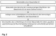
- Fig. 2 shows a flow chart of an exemplary embodiment of the method according to the invention for producing a vehicle composite window.
- a pane of glass 10 is provided.
- the glass pane 10 can be a laminated glass pane made of two individual panes of soda-lime glass, which are connected to one another via a PVB intermediate layer.
- a laminated glass pane of this type is produced using conventional methods under the action of heat, vacuum and / or pressure, for example using an autoclave method, vacuum bag or vacuum ring method or calender method.
- the interior surface I of the glass pane 10 is then prepared in that an adhesion promoter 5 is applied to the sensor area.
- the adhesion promoter 5 can be a paste with glass frits.
- the adhesion promoter 5 like a frame along the planned weld seam. Then the light guide body 4 is placed on the sensor area with the adhesion promoter 5. For the subsequent welding, infrared laser radiation L is focused on the entry surface 2 of the light guide element 4, which can take place through the glass pane 10 or through the light guide element 4. The laser radiation L is then moved along the side edge of the entry surface e of the light guide element. Glass pane 10 and light guide element 4 are thus welded to one another with the assistance of the adhesion promoter 5.
- Fig. 3 shows a cross-section of the vehicle window during laser welding.
- An adhesion promoter 5 is arranged in the edge area between the glass pane 10 and the light guide body 4.
- the adhesion promoter 5 is a paste containing glass frits.
- the radiation L of a pulsed Nd: YAG laser is focused through the light guide body 4 onto the entry surface e of the light guide body 4.
- the laser radiation L is then moved along the side edge of the entry surface e, so that a circumferential weld seam is formed with the aid of the adhesion promoter 5.
- the effect according to the invention is illustrated using a windshield with an installation angle ⁇ of 60 °.
- a camera is mounted behind the windshield.
- the light guide body 4 according to the invention results in a size of the camera window of the windshield of 40 cm 2 and a necessary total area of the black print in the camera area of 190 cm 2 .
- the size of the camera window is reduced to 1 cm 2 and the total area required for the black print is reduced to 130 cm 2 .
Landscapes
- Physics & Mathematics (AREA)
- Engineering & Computer Science (AREA)
- Mechanical Engineering (AREA)
- Optics & Photonics (AREA)
- General Physics & Mathematics (AREA)
- Chemical & Material Sciences (AREA)
- Plasma & Fusion (AREA)
- Materials Engineering (AREA)
- Organic Chemistry (AREA)
- Multimedia (AREA)
- Joining Of Glass To Other Materials (AREA)
- Window Of Vehicle (AREA)
- Optical Radar Systems And Details Thereof (AREA)
- Geophysics And Detection Of Objects (AREA)
Description
- Die Erfindung betrifft eine Fahrzeugscheibe, ein Verfahren zu ihrer Herstellung und ihre Verwendung.
- Moderne Fahrzeuge werden mit einer steigenden Anzahl an optischen Sensoren ausgestattet, deren Signale zur Unterstützung des Fahrers verwendet werden. Beispiele solcher Sensoren sind Kameras wie Fahrspurkameras oder Nachtsichtkameras, Regensensoren, Lichtsensoren oder Abstandsmesser. Nach vorne gerichtete Sensoren werden häufig an der innenraumseitigen Oberfläche der Windschutzscheibe befestigt, typischerweise mittig in der Nähe der Oberkannte. Die Sensoren werden durch einen opaken Abdeckdruck auf der Windschutzscheibe verdeckt. Dazu ist der übliche periphere, rahmenartige Abdeckdruck, der in erster Linie als UV-Schutz für den Montagekleber der Windschutzscheibe dient, im Bereich der Sensoren deutlich in Richtung der Scheibenmitte vergrößert.
- Herkömmliche Sensoren, insbesondere Kameras, sind so an der Windschutzscheibe angebracht, dass ihre Detektionsrichtung horizontal verläuft. Da die Windschutzscheibe stark geneigt im Fahrzeug installiert ist, beispielsweise mit einem Einbauwinkel von 60° zur Vertikalen, schließt die Detektionsrichtung des Sensors einen sehr spitzen Winkel von etwa 30° mit der Windschutzscheibe ein. Daraus resultiert ein vergleichsweise großer, im Wesentlichen trapezförmiger sogenannter Sensorbereich (oder Sensorfenster) der Windschutzscheibe. Der Sensorbereich ist derjenige Bereich der Windschutzscheibe, durch den verlaufende Strahlung durch den Sensor detektiert wird. Der Sensorbereich der Windschutzscheibe ist also der Bereich, der im Detektionsstrahlengang des Sensors liegt.
- Je mehr Sensoren an der Scheibe befestigt werden sollen, desto mehr Fläche der Windschutzscheibe wird durch die Summe der Sensorbereiche eingenommen und desto größer muss der Abdeckdruck ausgebildet werden, der die Sensoren verdecken soll. Dadurch wird allerdings die Gesamt-Lichttransmission durch die Scheibe herabgesetzt und sie wirkt häufig ästhetisch weniger ansprechend.
- Der Sensorbereich der Windschutzscheibe lässt sich dadurch verkleinern, dass der Winkel zwischen Sensor und Windschutzscheibe möglichst groß gewählt wird, idealerweise 90°. Damit die Detektionsrichtung des Sensors aber horizontal nach vorne gerichtet bleibt, muss der Detektionsstrahlengang in oder hinter der Scheibe entsprechend gelenkt werden. Es sind Lichtleitkörper bekannt, die zwischen dem Sensor und der Scheibe angebracht werden und aufgrund ihres Brechungsindex horizontal durch die Scheibe fallende Strahlung in den Sensor zu leiten.
EP 2181023 A1 offenbart einen solchen Lichtleitkörper aus Silikon, der an einer Windschutzscheibe angebracht ist. Ein Lichtleitkörper aus Glas ist beispielsweise ausUS 2008/0284850 A1 bekannt. Der Lichtleitkörper ist dort über eine Kunststofffolie mit Heizstrukturen mit der Windschutzscheibe verbunden, wahrscheinlich verklebt. - Auch
DE102008020954A1 offenbart eine Windschutzscheibe mit einem Lichtleitkörper aus Glas, der an der innenraumseitigen Oberfläche angeklebt ist. - Angeklebte Lichtleitkörper sind nicht sonderlich stabil und lösen sich leicht ungewollt von der Scheibe, beispielsweise beim Transport. Sie werden daher typischerweise erst beim Einbau der Scheibe in das Fahrzeug zusammen mit dem Sensor installiert. Da der Sensor eine genau auf den Scheibentyp abgestimmte Ausrichtung aufweisen muss, ist diese Art der Montage aufwendig.
- Der vorliegenden Erfindung liegt die Aufgabe zugrunde, eine weiter verbesserte Fahrzeugscheibe mit Lichtleitkörper bereitzustellen, wobei insbesondere die Verbindung zwischen Fahrzeugscheibe und Lichtleitkörper verbessert ist.
- Die Aufgabe der vorliegenden Erfindung wird erfindungsgemäß durch eine Fahrzeugscheibe gemäß Anspruch 1 gelöst. Bevorzugte Ausführungen gehen aus den Unteransprüchen hervor.
- Die erfindungsgemäße Fahrzeugscheibe ist zur Abtrennung eines Fahrzeug-Innenraums von einer äußeren Umgebung vorgesehen. Die Fahrzeugscheibe ist also eine Fensterscheibe, die in eine Fensteröffnung der Fahrzeugkarosserie eingesetzt ist oder dafür vorgesehen ist. Die erfindungsgemäße Fahrzeugscheibe ist insbesondere eine Windschutzscheibe eines Kraftfahrzeugs. Die Fahrzeugscheibe umfasst mindestens eine Glasscheibe. Diejenige Oberfläche der Glasscheibe beziehungsweise Fahrzeugscheibe, welche in Einbaulage der äußeren Umgebung des Fahrzeugs zugewandt ist, wird als außenseitige Oberfläche bezeichnet. Diejenige Oberfläche, welche in Einbaulage dem Innenraum des Fahrzeugs zugewandt ist, wird als innenraumseitige Oberfläche bezeichnet.
- Die Fahrzeugscheibe ist insbesondere dafür vorgesehen und geeignet, dass ein Sensor an ihrer innenraumseitigen Oberfläche befestigt wird. Dazu kann die innenraumseitige Oberfläche der Glasscheibe mit geeigneten Halterungen ausgestattet sein, beispielsweise mit einem Bracket oder Gehäuse. Der Bereich der Fahrzeugscheibe, der im Detektionsstrahlengang des Sensors angeordnet ist beziehungsweise dafür vorgesehen ist, wird als Sensorbereich oder Sensorfenster bezeichnet. Strahlung, die im Sensorbereich durch die Fahrzeugscheibe tritt, wird durch den Sensor detektiert.
- Die erfindungsgemäße Fahrzeugscheibe umfasst außerdem einen Lichtleitkörper, der auf einem Bereich der innenraumseitigen Oberfläche der Glasscheibe angeordnet ist. Der besagte Bereich der Glasscheibe entspricht mindestens dem Sensorbereich, kann aber auch größer sein. Die Größe des besagten Bereichs der Glasscheibe beträgt mindestens 4 cm2, beispielsweise von 10 cm2 bis 100 cm2, bevorzugt von 25 cm2 bis 50 cm2.
- Der Lichtleitkörper enthält oder besteht aus Glas. Der Lichtleitkörper ist dafür vorgesehen, Strahlung, die von außen durch die Fahrzeugscheibe tritt und durch den Sensor detektiert werden soll, abzulenken, insbesondere von der Scheibe wegzubrechen, so dass der Anstellwinkel des Sensors vergrößert wird. Da sich der Sensorbereich aus der Schnittfläche der Glasscheibe durch den Detektionskegel des Sensors ergibt, führt ein größerer Anstellwinkel zu einem kleineren Sensorbereich. Der Bereich der Fahrzeugscheibe, der zur Detektion verwendet wird und üblicherweise von einem opaken Abdeckdruck umgeben ist, um die dahinterliegenden Sensoren zu verdecken, kann so verkleinert werden, wodurch die Gesamt-Lichttransmission und das ästhetische Erscheinungsbild der Fahrzeugscheibe verbessert wird. Die Erfinder haben erkannt, dass mit einer Neigung des Sensors von 5° gegenüber der Horizontalen eine Verkleinerung des Sensorbereichs von über 50 % erreicht werden kann.
- Der Lichtleitkörper weist zwei Oberflächen auf, durch die die Strahlung auf dem Weg von der Glasscheibe zum Sensor hindurchtritt: eine erste, zur Glasscheibe hingewandte Oberfläche, durch die die Strahlung in den Lichtleitkörper eintritt, und eine zweite, von der Glasscheibe abgewandte Oberfläche, durch die die Strahlung aus dem Lichtleitkörper austritt. Die erste Oberfläche kann daher auch als Eintrittsfläche und die zweite Oberfläche als Austrittsfläche bezeichnet werden. Der Lichtleitkörper ist über die zur Glasscheibe hingewandte Eintrittsfläche mit der Glasscheibe verbunden, während der Sensor auf die von der Glasscheibe abgewandte Austrittsfläche gerichtet ist.
- Die Eintrittsfläche und die Austrittsfläche des Lichtleitkörpers müssen einen Winkel größer 0° miteinander einschließen, um die gewünschte Ablenkung des Detektionsstrahlengangs zu erreichen. Dieser Winkel wird im Sinne der Erfindung als Keilwinkel bezeichnet. Der Lichtleitkörper ist dabei so angeordnet, dass in der Richtung von der Unterkante zur Oberkante der Glasscheibe die Dicke des Lichtleitkörpers abnimmt. Die Oberkante ist dabei diejenige Seitenkante, die dafür vorgesehen ist, in Einbaulage nach oben zum Fahrzeugdach zu weisen (Dachkante). Die Unterkante ist diejenige Seitenkante, die dafür vorgesehen ist, in Einbaulage nach unten zum Motorraum zu weisen (Motorkante).
- Außer dem Keilwinkel bestehen keine weiteren Anforderungen an die geometrische Ausgestaltung des Lichtleitkörpers. Der Lichtleitkörper kann eine einfache Keilform mit einem dreieckigen Querschnitt aufweisen, aber auch einen trapezförmigen oder sogar höherpolygonalen Querschnitt.
- Je größer der Keilwinkel ist, desto stärker ist die Ablenkung der Strahlung und desto ausgeprägter ist der erfinderische Effekt. Allerdings steigt mit dem Keilwinkel auch die Ausdehnung des Lichtleitkörpers zwischen Glasscheibe und Sensor. Der Platzbedarf setzt der Größe des Keilwinkels daher Grenzen. Der Keilwinkel sollte mindestens 2°, bevorzugt mindestens 10° betragen, um eine vorteilhafte Ablenkung der Strahlung zu bewirken. Der Keilwinkel beträgt beispielsweise von 2° bis 30°, bevorzugt von 10° bis 25°.
- Erfindungsgemäß ist der Lichtleitkörper mittels Laserschweißen an der innenraumseitigen Oberfläche der Glasscheibe befestigt. Dadurch wird eine sehr stabile Verbindung zwischen Glasscheibe und Lichtleitkörper gewährleistet. Der Lichtleitkörper kann frühzeitig an der Glasscheibe befestigt und mit dieser zusammen transportiert werden. Beim Einbau der Scheibe in das Fahrzeug muss nur noch der Sensor hinter dem Lichtleitkörper befestigt werden. Das Ankleben des Lichtleitkörpers am Einsatzort und die aufwendige Anpassung der Kameraposition entfallen, wodurch der Einbau der Scheibe mit dem Sensor in das Fahrzeug erleichtert wird.
- Unter der erfindungsgemäßen Glasscheibe wird eine Scheibe, insbesondere Fensterscheibe, verstanden, die überwiegend aus Glas besteht. Die Glasscheibe kann eine einzelne monolithische Scheibe aus Glas sein, der Begriff schließt aber auch Scheiben ein, die neben dem Glas weitere Materialien beinhalten, beispielsweise bedruckte oder beklebte Gläser oder Glaslaminate.
- In einer bevorzugten Ausgestaltung ist die Glasscheibe ein solches Glaslaminat, nämlich ein Verbundglas, wie es im Fahrzeugbereich insbesondere für Windschutzscheiben üblich ist. Das Verbundglas umfasst eine Außenscheibe aus Glas und einer Innenscheibe aus Glas, die über eine thermoplastische Zwischenschicht miteinander verbunden sind. Mit Innenscheibe wird diejenige Scheibe bezeichnet, welche dafür vorgesehen ist, in Einbaulage dem Innenraum des Fahrzeugs zugewandt zu sein. Mit Außenscheibe wird diejenige Scheibe bezeichnet, welche dafür vorgesehen ist, in Einbaulage der äußeren Umgebung des Fahrzeugs zugewandt zu sein. Ist die Glasscheibe keine monolithische Scheibe, sondern ein Glaslaminat, so sollten innerhalb des Glaslaminats signifikanten Brechungsindexunterschiede auftreten. Dies ist bei typischen Fahrzeug-Verbundgläsern gewährleistet. Der maximale Unterschied der Brechungsindizes der Bestandteile des Glaslaminats im Strahlengang des Detektors sollte höchstens 0,05 betragen.
- In einer vorteilhaften Ausgestaltung entspricht der Brechungsindex des Lichtleitkörpers im Wesentlichen dem Brechungsindex der Glasscheibe. Das bedeutet im Sinne der Erfindung, dass der Unterschied der Brechungsindizes von Lichtleitkörper und Glasscheibe beziehungsweise ihrer einzelnen Bestandteile im Falle eines Glaslaminats) höchstens 0,05 betragen darf. Für die erfindungsgemäße strahlungslenkende Wirkung des Lichtleitkörpers ist die Abstimmung der Brechungsindizes zwar nicht zwingend erforderlich, jedoch kann hierdurch insbesondere eine chromatische Aberration vermieden werden. Ein großer Vorteil des Laserschweißens gegenüber anderen Befestigungsmethoden wie beispielsweise über einen Klebstoff ist es, dass Brechungsindex-Differenzen vermieden werden können. Der Brechungsindex im Sinne der Erfindung wird bei einer Wellenlänge von 550 nm gemessen.
- In einer bevorzugten Ausgestaltung enthält beziehungsweise besteht der Lichtleitkörper aus Kalk-Natronglas, Borosilikatglas, Aluminosilikatglas oder Quarzglas, besonders bevorzugt Kalk-Natronglas. Für das Laserschweißen ist es besonders vorteilhaft, wenn der Lichtleitkörper die gleiche Glassorte enthält wie die Glasscheibe.
- Die Glasscheibe enthält typischerweise Kalk-Natronglas, Borosilikatglas, Aluminosilikatglas oder Quarzglas, besonders bevorzugt Kalk-Natronglas, wie es für Fensterscheiben üblich ist. Kalk-Natron-Glas weist typischerweise Brechungsindizes von 1,5 bis 1,55 auf, insbesondere 1,52. Es können grundsätzlich aber auch andere Glassorten verwendet werden, wie Borosilikatglas (Brechungsindex beispielsweise 1,47), Aluminosilikatglas (Brechungsindex beispielsweise 1,5) oder Quarzglas (Brechungsindex beispielsweise 1,46).
- Ist die Glasscheibe eine Verbundscheibe, so enthält die thermoplastische Zwischenschicht bevorzugt Ethylenvinylacetat (EVA), Polyvinylbutyral (PVB) oder Polyurethan (PU) oder Gemische oder Copolymere oder Derivate davon, besonders bevorzugt PVB. Die Zwischenschicht kann aus einer Folie ausgebildet sein mit einer Dicke von bevorzugt 0,2 mm bis 2 mm, besonders bevorzugt von 0,3 mm bis 1 mm, beispielsweise 0,38 mm oder 0,76 mm. Die Zwischenschicht kann auch aus mehreren übereinandergelegten Folien ausgebildet sein oder aus Schichten unterschiedlichen Materials ausgebildet sein, wie es beispielsweise bei Folien mit geräuschmindernden Eigenschaften der Fall ist. Die Dicke der Außenscheibe und der Innenscheibe beträgt typischerweise von 0,5 mm bis 5 mm, bevorzugt von 1 mm bis 3 mm.
- Die zur Glasscheibe gewandte Eintrittsfläche des Lichtleitkörpers und der Bereich der innenraumseitigen Oberfläche der Glasscheibe, an dem der Lichtleitkörper befestigt ist, sind vorteilhafterweise parallel, so dass eine optimale Verbindung gewährleistet ist. Da Fahrzeugscheiben typischerweise gekrümmt sind, weist die Eintrittsfläche des Lichtleitkörpers bevorzugt ebenfalls eine Krümmung auf. Die Krümmung der Eintrittsfläche des Lichtleitkörpers ist dabei komplementär zur Krümmung des Bereichs der innenraumseitigen Oberfläche der Glasscheibe, auf dem der Lichtleitkörper angebracht ist. Unter komplementären Krümmungen werden Krümmungen von im Wesentlichen gleichem Krümmungsradius und gegensätzlicher Konvexität/Konkavität verstanden. Da die innenraumseitige Oberfläche von Fahrzeugscheiben typischerweise konkav gekrümmt sind, ist die Eintrittsfläche des Lichtleitkörpers bevorzugt konvex gekrümmt.
- In einer vorteilhaften Ausgestaltung ist die von der Glasscheibe abgewandte Austrittsfläche des Lichtleitkörpers als optische Linse ausgebildet. Die Austrittsfläche weist also eine konvexe oder konkave Krümmung auf. Insbesondere ist die Austrittsfläche konvex gekrümmt, um eine Fokussierung der durch den Lichtleitkörper tretenden Strahlung zu bewirken. Der Vorteil besteht darin, dass das typischerweise vorhandene optische System des Sensors vereinfacht gestaltet werden kann, da eine der Linsen direkt in den Lichtleitkörper integriert ist.
- Laserschweißen ist eine Technik, bei der ein Laserstrahl auf die Grenzfläche der beiden zu verbindenden Werkstücke fokussiert wird, welche dadurch gleichsam lokal aufgeschmolzen wird, was im Anschluss zu einer dauerhaft stabilen Verbindung führt. In einer bevorzugten Ausführung wird nicht die gesamte Grenzfläche zwischen Lichtleitkörper und Glasscheibe mit dem Laser behandelt, sondern es wird lediglich eine umlaufende Schweißnaht um Randbereich der Grenzfläche, bevorzugt entlang der Seitenkanten der Grenzfläche erzeugt. Dies ist für die stabile Verbindung ausreichend und vereinfacht den Schweißvorgang. Außerdem wird die optische Qualität der Glaselemente im Detektionsstrahlengang gewahrt. Erfindungsgemäß liegt die Eintrittsfläche des Lichtleitkörpers vollflächig auf dem Bereich der innenraumseitigen Oberfläche der Glasscheibe auf und ist mittels einer umlaufenden peripheren Schweißnaht mit der innenraumseitigen Oberfläche verbunden.
- Entlang der Schweißnaht ist ein Haftvermittler zwischen Glasscheibe und Lichtleitkörper angeordnet, insbesondere Glasfritten. Dadurch wird die Verbindung der beiden Werkstücke erleichtert und der Schweißvorgang vereinfacht. Der Haftvermittler enthält erfindungsgemäß Glasfritten.
- Ein weiterer Aspekt der Erfindung ist eine Anordnung, umfassend eine erfindungsgemäße Fahrzeugscheibe und einen daran angebrachten optischen Sensor, der an der innenraumseitigen Oberfläche befestigt ist und auf den Lichtleitkörper, insbesondere die Austrittsfläche des Lichtleitkörpers gerichtet ist. Der Detektionsstrahlengang des Sensors verläuft also durch den Lichtleitkörper hindurch. Der optische Sensor ist bevorzugt der Sensor einer optischen Kamera, das heißt einer Kamera mit Empfindlichkeit im sichtbaren Spektralbereich. Der Sensor kann beispielsweise ein CCD- oder CMOS-Sensor sein. Die Kamera kann beispielsweise eine Fahrspur-Kamera oder eine Kamera für ein Augmented Reality-Head-Up-Displays sein.
- Bei einer üblichen Fahrzeug-Verbundscheibe, die typischerweise aus zwei Scheiben aus Kalk-Natronglas und eine PVB-Zwischenschicht besteht, treten keine signifikanten Änderungen des Brechungsindex innerhalb der Verbundscheibe auf. Ein horizontal durch die Scheibe tretender Strahl wird dadurch parallelversetzt, bleibt aber auch nach Durchtritt durch die Scheibe horizontal, so dass der Sensor parallel zur Horizontalen ausgerichtet werden muss, um den Strahl zu detektieren. Durch den erfindungsgemäßen Lichtleitkörper kann der Sensor in einem größeren Winkel zur Fahrzeugscheibe angeordnet werden, wodurch der Sensorbereich der Fahrzeugscheibe kleiner wird. Dieser Effekt ist aus einfachen geometrischen Überlegungen heraus verständlich: der Sensorbereich entspricht der Schnittfläche durch den Detektionskegel des Sensors an der Position der Fahrzeugscheibe. Diese Fläche ist minimal bei einem Winkel von 90° und nimmt mit kleiner werdendem Winkel zu. Typischerweise sind Windschutzscheiben mit einem Einbauwinkel zur Vertikalen von etwa 60° angeordnet. Bei gekrümmten Scheiben wird zur Bestimmung des Einbauwinkels die Tangentialebene in der geometrischen Scheibenmitte herangezogen. Ein herkömmlicher nach vorne gerichteter Sensor mit horizontaler Ausrichtung schließt folglich einen Winkel von etwa 30° zur Windschutzscheibe ein. Durch die Ablenkung des Detektionsstrahlengangs mittels des erfindungsgemäßen Lichtleitkörpers kann der Winkel vorteilhaft vergrößert werden. Dadurch nimmt der Sensorbereich weniger Fläche der Fahrzeugscheibe ein, wodurch folglich auch der Abdeckdruck zur Verdeckung des Sensors kleiner ausgestaltet werden kann. Insbesondere, wenn mehrere Sensoren benachbart zueinander vorhanden sind, ist die Erfindung besonders vorteilhaft, weil ein übermäßig großer Abdeckdruck zur Kaschierung der Gesamtheit der Sensorbereiche vermieden werden kann. In einer bevorzugten Ausgestaltung ist der Sensor mit einem Winkel von 45° bis 90° zur Glasscheibe angeordnet. Zur exakten Bestimmung auch bei gekrümmten Scheiben ist der Winkel zwischen der zentralen Detektionsrichtung des Sensors (Mitte des Detektionskegels) und der Tangentialebene in der geometrischen Mitte des Sensorbereichs auf der innenraumseitigen Oberfläche der Glasscheibe heranzuziehen.
- Die Glasscheibe kann klar und farblos, aber auch getönt, getrübt oder gefärbt sein. Die Gesamttransmission durch die Glasscheibe beträgt in einer bevorzugten Ausgestaltung größer 70%, insbesondere wenn sie eine Windschutzscheibe ist. Der Begriff Gesamttransmission bezieht sich auf das durch ECE-R 43, Anhang 3, § 9.1 festgelegte Verfahren zur Prüfung der Lichtdurchlässigkeit von Kraftfahrzeugscheiben. Die Glasscheibe kann nicht vorgespannt, teilvorgespannt oder vorgespannt sein.
- Die Fahrzeugscheibe ist bevorzugt in einer oder in mehreren Richtungen des Raumes gebogen, wie es für Kraftfahrzeugscheiben üblich ist, wobei typische Krümmungsradien im Bereich von etwa 10 cm bis etwa 40 m liegen. Die Fahrzeugscheibe kann aber auch plan sein, beispielsweise wenn es als Scheibe für Busse, Züge oder Traktoren vorgesehen ist.
- Die Fahrzeugscheibe weist bevorzugt einen Abdeckdruck auf. Abdeckdrucke sind für Fahrzeugscheiben außerhalb des zentralen Sichtbereichs üblich, um Anbauteile zu verdecken oder den Klebstoff, mit dem die Fahrzeugscheibe mit der Karosserie verbunden ist, vor UV-Strahlung zu schützen. Der Abdeckdruck besteht typischerweise aus einem im Siebdruckverfahren aufgebrachten und eingebrannten schwarzen oder dunklen Emaille. Bevorzugt umrahmt der Abdeckdruck den Sensorbereich der Fahrzeugscheibe umlaufend, um den dahinterliegenden Sensor zu verdecken.
- Die Erfindung umfasst außerdem ein Verfahren zur Herstellung einer Fahrzeug-Verbundscheibe, wobei
- (a) ein Lichtleitkörper aus Glas auf einem Bereich einer innenraumseitigen Oberfläche einer Glasscheibe angeordnet wird, wobei die zur Glasscheibe hingewandte Oberfläche und die von der Glasscheibe abgewandte Oberfläche des Lichtleitkörpers einen Keilwinkel einschließen und in der Richtung von einer Unterkante zu einer Oberkante der Glasscheibe die Dicke des Lichtleitkörpers abnimmt,
- (b) der Lichtleitkörper mittels Laserschweißen an der Glasscheibe befestigt wird.
- Beim Laserschweißen wird die Strahlung eines Lasers auf die Grenzfläche zwischen Glasscheibe und Lichtleitkörper fokussiert, wodurch die beiden Glasoberflächen dauerhaft stabil miteinander verbunden werden. Die Laserstrahlung wird umlaufend entlang der Seitenkanten der Grenzfläche bewegt, oder im Randbereich der Grenzfläche in der Nähe der und im Wesentlichen parallel zu den Seitenkanten, um eine umlaufende, periphere Schweißnaht zu erzeugen. Der Laserstrahlung kann durch die Glasscheibe hindurch, durch den Lichtleitkörper hindurch oder auch seitlich auf die Grenzfläche gerichtet werden.
- Das Laserschweißen kann durch ein Vorheizen der Glasscheibe auf beispielsweise 200°C bis 300 °C erleichtert werden. Das erfindungsgemäße Verfahren wird aber bevorzugt bei Raumtemperatur durchgeführt. Zum einen entfällt dadurch das zeitaufwendige und energieintensive Vorheizen. Zum anderen bestünde bei einer fertig bereitgestellten, gebogenen und gegebenenfalls laminierten Fahrzeugscheibe durch das Erhitzen die Gefahr von optischen Beeinträchtigungen oder Delamination. Das Schweißen bei Raumtemperatur kann durch geeignete Haftvermittler vereinfacht werden.
- Erfindungsgemäß wird vor dem Laserschweißen ein solcher Haftvermittler zwischen dem Lichtleitkörper und der Glasscheibe zumindest im Bereich der zu erzeugenden Schweißnaht angeordnet. Als Haftvermittler eignen sich insbesondere Glasfritten, welche die Verbindung der beiden Glasoberflächen begünstigen. Der Haftvermittler enthält erfindungsgemäß Glasfritten.
- Die Glasfritten können rein in Pulverform aufgebracht werden. Einfacher zu handhaben ist aber eine Paste, die außer den Glasfritten Bindemittel, Lösungsmittel, Dispersionsmittel oberflächenaktive Stoffe oder weitere Bestandteile enthalten kann. Eine solche Paste lässt sich auch gut automatisiert applizieren, beispielsweise durch Siebdruckverfahren, Rakeln oder Extrusion mittels einer robotergeführten Düse. Je nach Zusammensetzung der Paste kann ein Vorheizen zur Beseitigung der organischen Bestandteile vorteilhaft oder erforderlich sein.
- Zum Laserschweißen wird bevorzugt ein Laser mit Strahlung im Infrarotbereich verwendet. Die Wellenlänge beträgt größer 800 nm, beispielsweise von 800 nm bis 20 µm. Besonders gute Ergebnisse werden mit einem Nd:YAG-Laser erreicht (1064 nm). Alternativ sind Diodenlaser besonders geeignet.
- Der Laser kann im Dauerstrichbetrieb oder gepulst betrieben werden. Durch einen gepulsten Betrieb können höhere Leistungsdichten erreicht werden, was für das Laserschweißen vorteilhaft ist.
- Die Ausgangsleistung des Lasers beträgt bevorzugt von 20 W bis 1 kW, beispielsweise von 50 W bis 500 W. Mit solchen Leistungen kann eine gute Schweißverbindung erzeugt werden. Damit werden besonders gute Ergebnisse erreicht.
- Vor dem Anschweißen kann der Lichtleitkörper bearbeitet werden, beispielsweise durch Schleifen. So kann beispielsweise die Austrittsfläche zu einer Linse geschliffen werden oder die Eintrittsfläche mit einer Krümmung versehen werden, um sie an die Glasscheibe anzupassen.
- Die Erfindung umfasst außerdem die Verwendung einer erfindungsgemäßen Fahrzeugscheibe als Windschutzscheibe eines Fahrzeugs, bevorzugt eines Kraftfahrzeugs. An der innenraumseitigen Oberfläche der Glasscheibe ist bevorzugt ein optischer Sensor befestigt, der auf die von der Fahrzeugscheibe abgewandte Oberfläche des Lichtleitkörpers gerichtet ist. Der Sensor ist bevorzugt ein CCD- oder CMOS-Chip einer optischen, das heißt im sichtbaren Spektralbereich empfindlichen Kamera, die beispielsweise eine Fahrspur-Kamera oder eine Kamera für ein Augmented Reality-Head-Up-Display ist.
- Im Folgenden wird die Erfindung anhand einer Zeichnung und Ausführungsbeispielen näher erläutert. Die Zeichnung ist eine schematische Darstellung und nicht maßstabsgetreu. Die Zeichnung schränkt die Erfindung in keiner Weise ein.
- Es zeigen:
- Fig. 1
- einen Querschnitt durch eine Ausgestaltung der erfindungsgemäßen Fahrzeugscheibe,
- Fig. 2
- ein Flussdiagramm einer Ausführungsform des erfindungsgemäßen Verfahrens und
- Fig. 3
- einen Querschnitt durch die Fahrzeugscheibe während des Anbringens des Lichtleitkörpers 4.
-
Fig. 1 zeigt einen Querschnitt einer erfindungsgemäßen Fahrzeugscheibe. Die Fahrzeugscheibe ist als Windschutzscheibe eines Personenkraftwagens vorgesehen und umfasst eine Glasscheibe 10, die als Verbundglas ausgebildet ist. Die Verbundscheibe besteht aus einer Außenscheibe 1 und einer Innenscheibe 2, die mittels einer thermoplastischen Zwischenschicht 3 flächig miteinander verbunden sind. Die Innenscheibe 2 ist in Einbaulage dem Innenraum des Fahrzeugs zugewandt. Die Außenscheibe 1 ist in Einbaulage der äußeren Umgebung des Fahrzeugs zugewandt. Die Außenscheibe 1 und die Innenscheibe 2 bestehen aus Kalk-Natron-Glas und weisen beispielsweise eine Dicke von 2,1 mm auf. Die Zwischenschicht 3 ist aus einer 0,76 mm dicke PVB-Folie ausgebildet. Die Glasscheibe 10 weist eine Oberkante O und eine Unterkante U auf. Die Oberkante O weist in Einbaulage nach oben zum Fahrzeugdach, die Unterkante U weist in Einbaulage nach unten zum Motorraum. - An der innenraumseitigen Oberfläche I der Glasscheibe 10 beziehungsweise der Innenscheibe 2 ist eine Sensor 7 angeordnet. Der Sensor 7 ist beispielsweise eine Fahrspurkamera. Die Detektionsrichtung des Sensors 7 ist außenseitig der Fahrzeugscheibe in etwa horizontal nach vorne gerichtet. Strahlung, die in einem sogenannten Sensorbereich horizontal durch die Glasscheibe 10 tritt, wird durch die Kamera detektiert.
- Die Fahrzeugscheibe ist, wie für Windschutzscheiben üblich, mit einem Einbauwinkel α von 60° zur Vertikalen in das Fahrzeug eingebaut. Bei einer herkömmlichen Fahrzeugscheibe müsste der Sensor 7 darum horizontal ausgerichtet werden, was zu einem spitzen Winkel β von etwa 30° zur innenraumseitigen Oberfläche I führen würde.
- Bei der erfindungsgemäßen Fahrzeugscheibe ist auf der innenraumseitigen Oberfläche I der Glasscheibe 10 im Sensorbereich ein Lichtleitkörper 4 angeordnet, welcher die zu detektierende Strahlung ablenkt. Der Lichtleitkörper 4 weist eine zur Glasscheibe 10 hingewandte Oberfläche e (Eintrittsfläche) auf, über die die Strahlung in ihn eintritt, und eine von der Glasscheibe 10 abgewandte Oberfläche a (Austrittsfläche), über die die Strahlung aus ihm austritt. Der Lichtleitkörper 4 ist über seine Eintrittsfläche e mit der Glasscheibe 10 verbunden, der Sensor 7 ist auf die Austrittsfläche a des Lichtleitkörpers 4 gerichtet. Die Eintrittsfläche e und die Austrittsfläche a sind mit einem Keilwinkel γ von beispielsweise 25° zueinander angeordnet. Der Lichtleitkörper 4 wirkt gleichsam als optisches Prisma. Durch den Lichtleitkörper 4 wird die horizontal von außen durch die Glasscheibe 10 tretende Strahlung gebrochen und der Sensor 7 kann in einem weniger spitzen Winkel β von beispielsweise 60° zur innenraumseitigen Oberfläche I der Glasscheibe 10 angeordnet werden. Dadurch kann der Platzbedarf des Sensorbereichs auf der Fahrzeugscheibe vorteilhaft verringert werden. Der Sensorbereich ergibt sich nämlich aus der Schnittfläche, die aus dem Schnitt der Glasscheibe 10 durch den Detektionskegel des Sensors 7 hervorgeht. Die Größe dieser Schnittfläche ist minimal bei einem Winkel β von 90° und nimmt mit abnehmendem Wert von β zu.
- In der dargestellten Ausgestaltung ist der Lichtleitkörper 4 als einfaches Prisma mit dreieckigem Querschnitt ausgeführt. Es sind aber auch andere Formen denkbar, beispielsweise ein Prisma mit trapezförmiger Grundfläche, solange der Keilwinkel γ zwischen Eintrittsfläche e und Austrittsfläche a vorhanden ist. Der Lichtleitkörper 4 ist so auf der Glasscheibe 10 angeordnet, dass die seine Dicke in der Richtung von der Unterkannte U zur Oberkante O abnimmt.
- Der Lichtleitkörper 4 besteht aus Kalk-Natron-Glas, ist also hinsichtlich seiner optischen und mechanischen Eigenschaften optimal auf die Glasscheibe 10 abgestimmt. Er ist mittels einer umlaufenden, peripheren Laser-Schweißnaht mit der Glasscheibe 10 verbunden.
- Die Glasscheibe 10 ist in der Zeichnung der Einfachheit halber plan dargestellt. In der Realität weisen Windschutzscheiben aber typischerweise eine Krümmung auf. Die innenraumseitige Oberfläche I der Glasscheibe 10 im Sensorbereich und die Eintrittsfläche e des Lichtleitkörpers sind aufeinander abgestimmt und komplementär zueinander ausgebildet, so dass die zu verbindenden Oberflächen parallel zueinander sind und schlüssig miteinander in Kontakt gebracht werden können.
- Die Oberfläche a des Lichtleitkörpers kann optional zur einer Linse geschliffen sein, so dass der Lichtleitkörper gleichzeitig Teil des optischen Systems des Sensors 7 ist.
-
Fig. 2 zeigt ein Flussdiagramm eines Ausführungsbeispiels des erfindungsgemäßen Verfahrens zur Herstellung einer Fahrzeug-Verbundscheibe. Zunächst wird eine Glasscheibe 10 bereitgestellt. Die Glasscheibe 10 kann eine Verbundglasscheibe sein aus zwei Einzelscheiben aus Kalk-Natron-Glas, die über eine PVB-Zwischenschicht miteinander verbunden sind. Eine solche Verbundglasscheibe wird mit fachüblichen Verfahren hergestellt unter Einwirkung Hitze, Vakuum und/oder Druck, beispielsweise mit Autoklavverfahren, Vakuumsack- oder Vakuumringverfahren oder Kalanderverfahren. Die innenraumseitige Oberfläche I der Glasscheibe 10 wird anschließend vorbereitet, indem ein Haftvermittler 5 auf den Sensorbereich aufgebracht wird. Der Haftvermittler 5 kann eine Paste mit Glasfritten sein. Es genügt, den Haftvermittler 5 rahmenartig aufzubringen entlang der geplanten Schweißnaht. Dann wird der Lichtleitkörper 4 auf den Sensorbereich mit dem Haftvermittler 5 aufgelegt. Zum anschließenden Verschweißen wird infrarote Laserstrahlung L auf die Eintrittsfläche 2 des Lichtleitelements 4 fokussiert, was durch die Glasscheibe 10 hindurch oder durch das Lichtleitelement 4 hindurch erfolgen kann. Die Laserstrahlung L wird anschließend entlang der Seitenkante der Eintrittsfläche e des Lichtleitelements bewegt. Glasscheibe 10 und Lichtleitelement 4 werden so unter Mitwirkung des Haftvermittlers 5 miteinander verschweißt. -
Fig. 3 zeigt einen Querschnitt der Fahrzeugscheibe während des Laserschweißens. Im Randbereich ist zwischen der Glasscheibe 10 und dem Lichtleitkörper 4 ein Haftvermittler 5 angeordnet. Der Haftvermittler 5 ist eine Paste enthaltend Glasfritten. Die Strahlung L eines gepulsten Nd:YAG-Lasers ist durch den Lichtleitkörper 4 hindurch auf die Eintrittsfläche e des Lichtleitkörpers 4 fokussiert. Die Laserstrahlung L wird dann entlang der Seitenkante der Eintrittsfläche e bewegt, so dass sich mit Hilfe des Haftvermittlers 5 eine umlaufende Schweißnaht ausbildet. - Der erfindungsgemäße Effekt wird anhand einer Windschutzscheibe mit einem Einbauwinkel α von 60° verdeutlicht. Hinter der Windschutzscheibe ist eine Kamera angebracht. Ohne erfindungsgemäßen Lichtleitkörper 4 ergeben sich eine Größe des Kamerafensters der Windschutzscheibe von 40 cm2 und eine nötige Gesamtfläche des Schwarzdrucks im Kamerabereich von 190 cm2. Mit einem erfindungsgemäßen Lichtleitkörper mit Keilwinkel γ von 25° und Optimierung des Einbauwinkels β verkleinert sich die Größe des Kamerafensters auf 1 cm2 und die nötige Gesamtfläche des Schwarzdrucks auf 130 cm2.
-
- (10)
- Glasscheibe
- (1)
- Außenscheibe
- (2)
- Innenscheibe
- (3)
- thermoplastische Zwischenschicht
- (4)
- Lichtleitkörper
- (5)
- Haftvermittler
- (7)
- Sensor
- (α)
- Einbauwinkel der Fahrzeugscheibe 10
- (β)
- Einbauwinkel des Sensors/der Kamera 7
- (γ)
- Keilwinkel des Lichtleitkörpers 4
- O
- Oberkante/Dachkante der Fahrzeugscheibe 10
- U
- Unterkante/Motorkante der Fahrzeugscheibe 10
- I
- innenraumseitige Oberfläche der Fahrzeugscheibe 10
- L
- Laserstrahlung
- e
- zur Fahrzeugscheibe 10 hingewandte Oberfläche des Lichtleitkörpers 4 (Eintrittsfläche)
- a
- von der Fahrzeugscheibe 10 abgewandte Oberfläche des Lichtleitkörpers 4 (Austrittsfläche)
Claims (12)
- Fahrzeugscheibe zur Abtrennung eines Fahrzeug-Innenraums von einer äußeren Umgebung, umfassend eine Glasscheibe (10) mit einem Lichtleitkörper (4) aus Glas auf einem Bereich der innenraumseitigen Oberfläche (I) der Glasscheibe (10),
wobei die zur Glasscheibe (10) hingewandte Oberfläche (e) und die von der Glasscheibe (10) abgewandte Oberfläche (a) des Lichtleitkörpers (4) einen Keilwinkel (γ) einschließen, so dass in der Richtung von einer Unterkante (U) zu einer Oberkante (O) der Glasscheibe (10) die Dicke des Lichtleitkörpers (4) abnimmt,
wobei der Lichtleitkörper (4) mittels Laserschweißen an der innenraumseitigen Oberfläche (I) der Glasscheibe (10) befestigt ist,
wobei die zur Glasscheibe (10) hingewandte Oberfläche (e) des Lichtleitkörpers (4) vollflächig auf dem Bereich der innenraumseitigen Oberfläche (I) der Glasscheibe (10) aufliegt und mittels einer umlaufenden peripheren Schweißnaht mit der innenraumseitigen Oberfläche (I) verbunden ist,
gekennzeichnet dadurch, dass entlang der Schweißnaht ein Haftvermittler zwischen Glasscheibe (10) und Lichtleitkörper (4) angeordnet ist, der Glasfritten enthält. - Fahrzeugscheibe nach Anspruch 1, wobei der Brechungsindex des Lichtleitkörpers (4) im Wesentlichen dem Brechungsindex der Glasscheibe (10) entspricht.
- Fahrzeugscheibe nach Anspruch 1 oder 2, wobei der Lichtleitkörper (4) Kalk-Natronglas, Borosilikatglas, Aluminosilikatglas oder Quarzglas enthält, bevorzugt Kalk-Natronglas.
- Fahrzeugscheibe nach einem der Ansprüche 1 bis 3, wobei die Krümmung der zur Glasscheibe (10) hingewandten Oberfläche (e) des Lichtleitkörpers (4) zur Krümmung des Bereichs der innenraumseitigen Oberfläche (I) der Glasscheibe (10), auf dem der Lichtleitkörper (4) angebracht ist, komplementär ist.
- Fahrzeugscheibe nach einem der Ansprüche 1 bis 4, wobei der Keilwinkel (γ) des Lichtleitkörpers (4) mindestens 2° beträgt, bevorzugt mindestens 10°.
- Fahrzeugscheibe nach einem der Ansprüche 1 bis 5, wobei die von der Glasscheibe (10) abgewandte Oberfläche (a) des Lichtleitkörpers (4) als Linse ausgebildet ist.
- Fahrzeugscheibe nach einem der Ansprüche 1 bis 6, wobei an der Glasscheibe (10) ein optischer Sensor (7) befestigt ist, der auf die von der Glasscheibe (10) abgewandte Oberfläche (a) des Lichtleitkörpers (4) gerichtet ist.
- Verfahren zur Herstellung einer Fahrzeugscheibe, wobei(a) ein Lichtleitkörper (4) aus Glas auf einem Bereich einer innenraumseitigen Oberfläche (I) einer Glasscheibe (10) angeordnet wird, wobei die zur Glasscheibe (10) hingewandte Oberfläche (e) und die von der Glasscheibe (10) abgewandte Oberfläche (a) des Lichtleitkörpers (4) einen Keilwinkel (γ) einschließen und in der Richtung von einer Unterkante (U) zu einer Oberkante (O) der Glasscheibe (10) die Dicke des Lichtleitkörpers (4) abnimmt,(b) der Lichtleitkörper (4) mittels Laserschweißen an der Glasscheibe (I) befestigt wird,wobei Glasfritten zwischen dem Lichtleitkörper (4) und der Glasscheibe (10) angeordnet werden.
- Verfahren nach Anspruch 8, wobei in Schritt (b) Laserstrahlung umlaufend entlang der oder parallel zur Seitenkante der zur Glasscheibe (10) hingewandte Oberfläche (e) des Lichtleitkörpers (4) bewegt wird.
- Verfahren nach Anspruch 8 oder 9, wobei das Laserschweißen bei Raumtemperatur durchgeführt wird.
- Verfahren nach einem der Ansprüche 8 bis 10, wobei beim Laserschweißen ein Laser mit einer Ausgangsleistung von 20 W bis 1 kW, bevorzugt von 50 W bis 500 W verwendet wird.
- Verwendung einer Fahrzeugscheibe nach einem der Ansprüche 1 bis 7 als Windschutzscheibe eines Fahrzeugs, bevorzugt eines Kraftfahrzeugs, wobei an der innenraumseitigen Oberfläche (l) der Glasscheibe (10) ein optischer Sensor (7) befestigt ist, der auf die von der Fahrzeugscheibe (10) abgewandte Oberfläche (a) des Lichtleitkörpers (4) gerichtet ist.
Priority Applications (1)
| Application Number | Priority Date | Filing Date | Title |
|---|---|---|---|
| PL17804106T PL3538399T3 (pl) | 2016-11-14 | 2017-11-09 | Szyba pojazdu z korpusem przewodzącym światło dla czujnika |
Applications Claiming Priority (2)
| Application Number | Priority Date | Filing Date | Title |
|---|---|---|---|
| EP16198566 | 2016-11-14 | ||
| PCT/EP2017/078750 WO2018087223A1 (de) | 2016-11-14 | 2017-11-09 | Fahrzeugscheibe mit lichtleitkörper für einen sensor |
Publications (2)
| Publication Number | Publication Date |
|---|---|
| EP3538399A1 EP3538399A1 (de) | 2019-09-18 |
| EP3538399B1 true EP3538399B1 (de) | 2020-09-09 |
Family
ID=57288272
Family Applications (1)
| Application Number | Title | Priority Date | Filing Date |
|---|---|---|---|
| EP17804106.7A Not-in-force EP3538399B1 (de) | 2016-11-14 | 2017-11-09 | Fahrzeugscheibe mit lichtleitkörper für einen sensor |
Country Status (14)
| Country | Link |
|---|---|
| US (1) | US10703253B2 (de) |
| EP (1) | EP3538399B1 (de) |
| JP (1) | JP6625788B2 (de) |
| KR (1) | KR102174074B1 (de) |
| CN (1) | CN108323165B (de) |
| BR (1) | BR112019000951A2 (de) |
| CA (1) | CA3042473A1 (de) |
| ES (1) | ES2824524T3 (de) |
| HU (1) | HUE052254T2 (de) |
| MA (1) | MA46751B1 (de) |
| MX (1) | MX392347B (de) |
| PL (1) | PL3538399T3 (de) |
| RU (1) | RU2712388C1 (de) |
| WO (1) | WO2018087223A1 (de) |
Families Citing this family (5)
| Publication number | Priority date | Publication date | Assignee | Title |
|---|---|---|---|---|
| US11052639B2 (en) * | 2017-07-27 | 2021-07-06 | Saint-Gobain Glass France | Thermoplastic film for a laminated glass pane |
| US11662467B2 (en) | 2017-11-28 | 2023-05-30 | Innoviz Technologies Ltd. | MEMS mirror having spaced actuators |
| JP7473563B2 (ja) * | 2019-04-05 | 2024-04-23 | エージーシー グラス ユーロップ | 反射防止ユニットを備える自動車用LiDARアセンブリ |
| JP7814656B2 (ja) * | 2020-08-25 | 2026-02-17 | ショット アクチエンゲゼルシャフト | 環境の影響への耐久性を高めた車両用ガラス板 |
| US20240248317A1 (en) * | 2021-06-29 | 2024-07-25 | Agc Glass Europe | Optical wedge element for glazing equipped with optical sensor |
Family Cites Families (14)
| Publication number | Priority date | Publication date | Assignee | Title |
|---|---|---|---|---|
| DE10080608D2 (de) * | 1999-03-15 | 2001-11-29 | Daimler Chrysler Ag | System zur Blickfelderweiterung im KFZ |
| IL148804A (en) | 2002-03-21 | 2007-02-11 | Yaacov Amitai | Optical device |
| DE10219393A1 (de) * | 2002-04-30 | 2003-11-20 | Webasto Vehicle Sys Int Gmbh | Optische Einrichtung zur Vergrößerung des Sichtbereichs |
| RU39209U1 (ru) * | 2004-03-29 | 2004-07-20 | Ерещенко Михаил Викторович | Автомобильный компьютер |
| DE102004024735A1 (de) * | 2004-05-19 | 2005-12-15 | Leopold Kostal Gmbh & Co Kg | Kameraanordnung für ein Kraftfahrzeug |
| DE102006010672A1 (de) | 2006-03-08 | 2007-09-13 | Leopold Kostal Gmbh & Co. Kg | Kameraanordnung für ein Kraftfahrzeug |
| DE102007039776A1 (de) | 2007-08-23 | 2009-02-26 | Leopold Kostal Gmbh & Co. Kg | Optischer Koppelkörper |
| US8451541B2 (en) * | 2007-12-07 | 2013-05-28 | Saint-Gobain Glass France | Curved vehicle windshield made from laminated glass |
| DE102008020954A1 (de) * | 2008-04-25 | 2009-10-29 | Ifm Electronic Gmbh | Kameraanordnung für ein Kraftfahrzeug |
| DE102008023845B4 (de) * | 2008-05-16 | 2018-04-05 | Trw Automotive Electronics & Components Gmbh | Optische Sensorvorrichtung zur Detektion von Umgebungslicht |
| DE102009000005A1 (de) * | 2009-01-02 | 2010-07-08 | Robert Bosch Gmbh | Kameraanordnung und Verfahren zur Erfassung einer Fahrzeugumgebung |
| JP2011111349A (ja) * | 2009-11-25 | 2011-06-09 | Hamamatsu Photonics Kk | ガラス溶着方法 |
| EP2390141B1 (de) * | 2010-05-31 | 2014-09-24 | Volvo Car Corporation | Optische Sensorschnittstelle |
| DE102011009075B4 (de) * | 2011-01-21 | 2021-07-22 | Kostal Automobil Elektrik Gmbh & Co. Kg | Kameraanordnung für ein Kraftfahrzeug |
-
2017
- 2017-11-09 MA MA46751A patent/MA46751B1/fr unknown
- 2017-11-09 BR BR112019000951-5A patent/BR112019000951A2/pt active Search and Examination
- 2017-11-09 US US16/349,550 patent/US10703253B2/en not_active Expired - Fee Related
- 2017-11-09 RU RU2019107434A patent/RU2712388C1/ru active
- 2017-11-09 ES ES17804106T patent/ES2824524T3/es active Active
- 2017-11-09 PL PL17804106T patent/PL3538399T3/pl unknown
- 2017-11-09 CA CA3042473A patent/CA3042473A1/en not_active Abandoned
- 2017-11-09 HU HUE17804106A patent/HUE052254T2/hu unknown
- 2017-11-09 CN CN201780003124.7A patent/CN108323165B/zh not_active Expired - Fee Related
- 2017-11-09 KR KR1020197016747A patent/KR102174074B1/ko not_active Expired - Fee Related
- 2017-11-09 JP JP2019510674A patent/JP6625788B2/ja not_active Expired - Fee Related
- 2017-11-09 EP EP17804106.7A patent/EP3538399B1/de not_active Not-in-force
- 2017-11-09 MX MX2019005543A patent/MX392347B/es unknown
- 2017-11-09 WO PCT/EP2017/078750 patent/WO2018087223A1/de not_active Ceased
Non-Patent Citations (1)
| Title |
|---|
| None * |
Also Published As
| Publication number | Publication date |
|---|---|
| KR20190082890A (ko) | 2019-07-10 |
| JP6625788B2 (ja) | 2019-12-25 |
| BR112019000951A2 (pt) | 2019-05-21 |
| JP2019534226A (ja) | 2019-11-28 |
| ES2824524T3 (es) | 2021-05-12 |
| MX392347B (es) | 2025-03-24 |
| US20190263315A1 (en) | 2019-08-29 |
| HUE052254T2 (hu) | 2021-04-28 |
| EP3538399A1 (de) | 2019-09-18 |
| CA3042473A1 (en) | 2018-05-17 |
| CN108323165A (zh) | 2018-07-24 |
| PL3538399T3 (pl) | 2020-12-28 |
| WO2018087223A1 (de) | 2018-05-17 |
| MA46751B1 (fr) | 2020-10-28 |
| US10703253B2 (en) | 2020-07-07 |
| CN108323165B (zh) | 2022-07-08 |
| KR102174074B1 (ko) | 2020-11-05 |
| RU2712388C1 (ru) | 2020-01-28 |
| MX2019005543A (es) | 2019-07-04 |
Similar Documents
| Publication | Publication Date | Title |
|---|---|---|
| EP3538399B1 (de) | Fahrzeugscheibe mit lichtleitkörper für einen sensor | |
| EP3610323B1 (de) | Verbundscheibe mit funktionselement mit elektrisch steuerbaren optischen eigenschaften | |
| EP3484707B1 (de) | Fahrzeug-verbundscheibe mit optimiertem strahlengang für einen daran angebrachten sensor | |
| EP3429876B1 (de) | Windschutzscheibe mit elektrisch regelbarer sonnenblende | |
| WO2022073860A1 (de) | Fahrzeugscheibe für head-up-display | |
| EP3507091B1 (de) | Verbundscheibe für ein head-up-display | |
| WO2022073894A1 (de) | Fahrzeugscheibe für head-up-display | |
| EP3802117B1 (de) | Verbundscheibe mit funktionselement mit elektrisch steuerbaren optischen eigenschaften | |
| EP3802118B1 (de) | Funktionselement mit elektrisch steuerbaren optischen eigenschaften | |
| EP3706997B1 (de) | Verbundscheibe mit funktionselement mit elektrisch steuerbaren optischen eigenschaften | |
| EP3758936A1 (de) | Verfahren zur herstellung einer verbundscheibe mit funktionselement mit elektrisch steuerbaren optischen eigenschaften | |
| EP2796288B1 (de) | Fahrzeugscheibe mit einem optischen Filter | |
| EP3826837A1 (de) | Fahrzeug-verbundscheibe mit opaker polymerer folie | |
| EP3691891A1 (de) | Verbundscheibe mit elektrisch steuerbaren optischen eigenschaften | |
| WO2019242915A1 (de) | Verfahren zur herstellung einer verbundscheibe mit polarisationsselektiver beschichtung | |
| WO2022161894A1 (de) | Fahrzeugscheibe für head-up-display | |
| DE202019103729U1 (de) | Fahrzeug-Verbundscheibe mit opaker polymerer Folie | |
| DE202022002921U1 (de) | Verbundscheibe mit Funktionsfolie mit opakem Aufdruck | |
| DE19644004A1 (de) | IR-reflektierende Verbundglasscheibe und Verfahren zu ihrer Herstellung | |
| DE202023002828U1 (de) | Anordnung für ein Fahrerassistenzsystem | |
| EP4408692A1 (de) | Anordnung für fahrerassistenzsystem | |
| WO2023046477A1 (de) | Verglasung mit segmentiertem pdlc-funktionselement und elektrisch steuerbaren optischen eigenschaften | |
| DE202021100222U1 (de) | Verbundscheibe mit Sonnenblendschutz-Bereich mit verbesserter Wärmeschutzfunktion | |
| EP3756882A1 (de) | Fahrzeug-verbundscheibe mit sensorbereich und keilwinkelförmiger thermoplastischer zwischenschicht im sensorbereich | |
| WO2024068173A1 (de) | Fahrzeugverglasung und anordnung für ein fahrerassistenzsystem |
Legal Events
| Date | Code | Title | Description |
|---|---|---|---|
| STAA | Information on the status of an ep patent application or granted ep patent |
Free format text: STATUS: UNKNOWN |
|
| STAA | Information on the status of an ep patent application or granted ep patent |
Free format text: STATUS: THE INTERNATIONAL PUBLICATION HAS BEEN MADE |
|
| PUAI | Public reference made under article 153(3) epc to a published international application that has entered the european phase |
Free format text: ORIGINAL CODE: 0009012 |
|
| STAA | Information on the status of an ep patent application or granted ep patent |
Free format text: STATUS: REQUEST FOR EXAMINATION WAS MADE |
|
| 17P | Request for examination filed |
Effective date: 20190425 |
|
| AK | Designated contracting states |
Kind code of ref document: A1 Designated state(s): AL AT BE BG CH CY CZ DE DK EE ES FI FR GB GR HR HU IE IS IT LI LT LU LV MC MK MT NL NO PL PT RO RS SE SI SK SM TR |
|
| AX | Request for extension of the european patent |
Extension state: BA ME |
|
| DAX | Request for extension of the european patent (deleted) | ||
| RAV | Requested validation state of the european patent: fee paid |
Extension state: MA Effective date: 20190425 |
|
| RAP1 | Party data changed (applicant data changed or rights of an application transferred) |
Owner name: SAINT-GOBAIN GLASS FRANCE |
|
| GRAP | Despatch of communication of intention to grant a patent |
Free format text: ORIGINAL CODE: EPIDOSNIGR1 |
|
| STAA | Information on the status of an ep patent application or granted ep patent |
Free format text: STATUS: GRANT OF PATENT IS INTENDED |
|
| GRAS | Grant fee paid |
Free format text: ORIGINAL CODE: EPIDOSNIGR3 |
|
| GRAA | (expected) grant |
Free format text: ORIGINAL CODE: 0009210 |
|
| STAA | Information on the status of an ep patent application or granted ep patent |
Free format text: STATUS: THE PATENT HAS BEEN GRANTED |
|
| INTG | Intention to grant announced |
Effective date: 20200714 |
|
| AK | Designated contracting states |
Kind code of ref document: B1 Designated state(s): AL AT BE BG CH CY CZ DE DK EE ES FI FR GB GR HR HU IE IS IT LI LT LU LV MC MK MT NL NO PL PT RO RS SE SI SK SM TR |
|
| REG | Reference to a national code |
Ref country code: GB Ref legal event code: FG4D Free format text: NOT ENGLISH |
|
| REG | Reference to a national code |
Ref country code: AT Ref legal event code: REF Ref document number: 1311193 Country of ref document: AT Kind code of ref document: T Effective date: 20200915 Ref country code: CH Ref legal event code: EP |
|
| REG | Reference to a national code |
Ref country code: DE Ref legal event code: R096 Ref document number: 502017007234 Country of ref document: DE |
|
| REG | Reference to a national code |
Ref country code: IE Ref legal event code: FG4D Free format text: LANGUAGE OF EP DOCUMENT: GERMAN |
|
| REG | Reference to a national code |
Ref country code: MA Ref legal event code: VAGR Ref document number: 46751 Country of ref document: MA Kind code of ref document: B1 |
|
| REG | Reference to a national code |
Ref country code: NL Ref legal event code: FP |
|
| REG | Reference to a national code |
Ref country code: SK Ref legal event code: T3 Ref document number: E 35812 Country of ref document: SK |
|
| REG | Reference to a national code |
Ref country code: LT Ref legal event code: MG4D |
|
| PG25 | Lapsed in a contracting state [announced via postgrant information from national office to epo] |
Ref country code: LT Free format text: LAPSE BECAUSE OF FAILURE TO SUBMIT A TRANSLATION OF THE DESCRIPTION OR TO PAY THE FEE WITHIN THE PRESCRIBED TIME-LIMIT Effective date: 20200909 Ref country code: GR Free format text: LAPSE BECAUSE OF FAILURE TO SUBMIT A TRANSLATION OF THE DESCRIPTION OR TO PAY THE FEE WITHIN THE PRESCRIBED TIME-LIMIT Effective date: 20201210 Ref country code: BG Free format text: LAPSE BECAUSE OF FAILURE TO SUBMIT A TRANSLATION OF THE DESCRIPTION OR TO PAY THE FEE WITHIN THE PRESCRIBED TIME-LIMIT Effective date: 20201209 Ref country code: HR Free format text: LAPSE BECAUSE OF FAILURE TO SUBMIT A TRANSLATION OF THE DESCRIPTION OR TO PAY THE FEE WITHIN THE PRESCRIBED TIME-LIMIT Effective date: 20200909 Ref country code: FI Free format text: LAPSE BECAUSE OF FAILURE TO SUBMIT A TRANSLATION OF THE DESCRIPTION OR TO PAY THE FEE WITHIN THE PRESCRIBED TIME-LIMIT Effective date: 20200909 Ref country code: NO Free format text: LAPSE BECAUSE OF FAILURE TO SUBMIT A TRANSLATION OF THE DESCRIPTION OR TO PAY THE FEE WITHIN THE PRESCRIBED TIME-LIMIT Effective date: 20201209 |
|
| PG25 | Lapsed in a contracting state [announced via postgrant information from national office to epo] |
Ref country code: RS Free format text: LAPSE BECAUSE OF FAILURE TO SUBMIT A TRANSLATION OF THE DESCRIPTION OR TO PAY THE FEE WITHIN THE PRESCRIBED TIME-LIMIT Effective date: 20200909 Ref country code: LV Free format text: LAPSE BECAUSE OF FAILURE TO SUBMIT A TRANSLATION OF THE DESCRIPTION OR TO PAY THE FEE WITHIN THE PRESCRIBED TIME-LIMIT Effective date: 20200909 |
|
| REG | Reference to a national code |
Ref country code: HU Ref legal event code: AG4A Ref document number: E052254 Country of ref document: HU |
|
| PG25 | Lapsed in a contracting state [announced via postgrant information from national office to epo] |
Ref country code: PT Free format text: LAPSE BECAUSE OF FAILURE TO SUBMIT A TRANSLATION OF THE DESCRIPTION OR TO PAY THE FEE WITHIN THE PRESCRIBED TIME-LIMIT Effective date: 20210111 Ref country code: EE Free format text: LAPSE BECAUSE OF FAILURE TO SUBMIT A TRANSLATION OF THE DESCRIPTION OR TO PAY THE FEE WITHIN THE PRESCRIBED TIME-LIMIT Effective date: 20200909 Ref country code: SM Free format text: LAPSE BECAUSE OF FAILURE TO SUBMIT A TRANSLATION OF THE DESCRIPTION OR TO PAY THE FEE WITHIN THE PRESCRIBED TIME-LIMIT Effective date: 20200909 |
|
| REG | Reference to a national code |
Ref country code: ES Ref legal event code: FG2A Ref document number: 2824524 Country of ref document: ES Kind code of ref document: T3 Effective date: 20210512 |
|
| PG25 | Lapsed in a contracting state [announced via postgrant information from national office to epo] |
Ref country code: IS Free format text: LAPSE BECAUSE OF FAILURE TO SUBMIT A TRANSLATION OF THE DESCRIPTION OR TO PAY THE FEE WITHIN THE PRESCRIBED TIME-LIMIT Effective date: 20210109 Ref country code: AL Free format text: LAPSE BECAUSE OF FAILURE TO SUBMIT A TRANSLATION OF THE DESCRIPTION OR TO PAY THE FEE WITHIN THE PRESCRIBED TIME-LIMIT Effective date: 20200909 |
|
| REG | Reference to a national code |
Ref country code: DE Ref legal event code: R097 Ref document number: 502017007234 Country of ref document: DE |
|
| PG25 | Lapsed in a contracting state [announced via postgrant information from national office to epo] |
Ref country code: MC Free format text: LAPSE BECAUSE OF FAILURE TO SUBMIT A TRANSLATION OF THE DESCRIPTION OR TO PAY THE FEE WITHIN THE PRESCRIBED TIME-LIMIT Effective date: 20200909 |
|
| REG | Reference to a national code |
Ref country code: CH Ref legal event code: PL |
|
| PLBE | No opposition filed within time limit |
Free format text: ORIGINAL CODE: 0009261 |
|
| STAA | Information on the status of an ep patent application or granted ep patent |
Free format text: STATUS: NO OPPOSITION FILED WITHIN TIME LIMIT |
|
| 26N | No opposition filed |
Effective date: 20210610 |
|
| PG25 | Lapsed in a contracting state [announced via postgrant information from national office to epo] |
Ref country code: CH Free format text: LAPSE BECAUSE OF NON-PAYMENT OF DUE FEES Effective date: 20201130 Ref country code: LI Free format text: LAPSE BECAUSE OF NON-PAYMENT OF DUE FEES Effective date: 20201130 Ref country code: DK Free format text: LAPSE BECAUSE OF FAILURE TO SUBMIT A TRANSLATION OF THE DESCRIPTION OR TO PAY THE FEE WITHIN THE PRESCRIBED TIME-LIMIT Effective date: 20200909 Ref country code: SI Free format text: LAPSE BECAUSE OF FAILURE TO SUBMIT A TRANSLATION OF THE DESCRIPTION OR TO PAY THE FEE WITHIN THE PRESCRIBED TIME-LIMIT Effective date: 20200909 |
|
| PG25 | Lapsed in a contracting state [announced via postgrant information from national office to epo] |
Ref country code: IE Free format text: LAPSE BECAUSE OF NON-PAYMENT OF DUE FEES Effective date: 20201109 |
|
| PGFP | Annual fee paid to national office [announced via postgrant information from national office to epo] |
Ref country code: NL Payment date: 20211014 Year of fee payment: 5 |
|
| PGFP | Annual fee paid to national office [announced via postgrant information from national office to epo] |
Ref country code: CZ Payment date: 20211015 Year of fee payment: 5 Ref country code: ES Payment date: 20211207 Year of fee payment: 5 Ref country code: RO Payment date: 20211025 Year of fee payment: 5 Ref country code: TR Payment date: 20211108 Year of fee payment: 5 Ref country code: SE Payment date: 20211012 Year of fee payment: 5 Ref country code: LU Payment date: 20211025 Year of fee payment: 5 Ref country code: SK Payment date: 20211013 Year of fee payment: 5 |
|
| PGFP | Annual fee paid to national office [announced via postgrant information from national office to epo] |
Ref country code: IT Payment date: 20211012 Year of fee payment: 5 Ref country code: HU Payment date: 20211013 Year of fee payment: 5 Ref country code: BE Payment date: 20211018 Year of fee payment: 5 |
|
| PGFP | Annual fee paid to national office [announced via postgrant information from national office to epo] |
Ref country code: PL Payment date: 20211012 Year of fee payment: 5 |
|
| PG25 | Lapsed in a contracting state [announced via postgrant information from national office to epo] |
Ref country code: MT Free format text: LAPSE BECAUSE OF FAILURE TO SUBMIT A TRANSLATION OF THE DESCRIPTION OR TO PAY THE FEE WITHIN THE PRESCRIBED TIME-LIMIT Effective date: 20200909 Ref country code: CY Free format text: LAPSE BECAUSE OF FAILURE TO SUBMIT A TRANSLATION OF THE DESCRIPTION OR TO PAY THE FEE WITHIN THE PRESCRIBED TIME-LIMIT Effective date: 20200909 |
|
| PG25 | Lapsed in a contracting state [announced via postgrant information from national office to epo] |
Ref country code: MK Free format text: LAPSE BECAUSE OF FAILURE TO SUBMIT A TRANSLATION OF THE DESCRIPTION OR TO PAY THE FEE WITHIN THE PRESCRIBED TIME-LIMIT Effective date: 20200909 |
|
| PGFP | Annual fee paid to national office [announced via postgrant information from national office to epo] |
Ref country code: GB Payment date: 20220930 Year of fee payment: 6 |
|
| PGFP | Annual fee paid to national office [announced via postgrant information from national office to epo] |
Ref country code: FR Payment date: 20221010 Year of fee payment: 6 |
|
| PGFP | Annual fee paid to national office [announced via postgrant information from national office to epo] |
Ref country code: DE Payment date: 20220621 Year of fee payment: 6 |
|
| REG | Reference to a national code |
Ref country code: SK Ref legal event code: MM4A Ref document number: E 35812 Country of ref document: SK Effective date: 20221109 |
|
| REG | Reference to a national code |
Ref country code: SE Ref legal event code: EUG |
|
| REG | Reference to a national code |
Ref country code: NL Ref legal event code: MM Effective date: 20221201 |
|
| REG | Reference to a national code |
Ref country code: BE Ref legal event code: MM Effective date: 20221130 |
|
| PG25 | Lapsed in a contracting state [announced via postgrant information from national office to epo] |
Ref country code: RO Free format text: LAPSE BECAUSE OF NON-PAYMENT OF DUE FEES Effective date: 20221109 Ref country code: HU Free format text: LAPSE BECAUSE OF NON-PAYMENT OF DUE FEES Effective date: 20221110 Ref country code: CZ Free format text: LAPSE BECAUSE OF NON-PAYMENT OF DUE FEES Effective date: 20221109 |
|
| PG25 | Lapsed in a contracting state [announced via postgrant information from national office to epo] |
Ref country code: SK Free format text: LAPSE BECAUSE OF NON-PAYMENT OF DUE FEES Effective date: 20221109 Ref country code: SE Free format text: LAPSE BECAUSE OF NON-PAYMENT OF DUE FEES Effective date: 20221110 Ref country code: NL Free format text: LAPSE BECAUSE OF NON-PAYMENT OF DUE FEES Effective date: 20221201 Ref country code: LU Free format text: LAPSE BECAUSE OF NON-PAYMENT OF DUE FEES Effective date: 20221109 |
|
| PG25 | Lapsed in a contracting state [announced via postgrant information from national office to epo] |
Ref country code: IT Free format text: LAPSE BECAUSE OF NON-PAYMENT OF DUE FEES Effective date: 20221109 |
|
| PG25 | Lapsed in a contracting state [announced via postgrant information from national office to epo] |
Ref country code: BE Free format text: LAPSE BECAUSE OF NON-PAYMENT OF DUE FEES Effective date: 20221130 |
|
| REG | Reference to a national code |
Ref country code: ES Ref legal event code: FD2A Effective date: 20231228 |
|
| REG | Reference to a national code |
Ref country code: AT Ref legal event code: MM01 Ref document number: 1311193 Country of ref document: AT Kind code of ref document: T Effective date: 20221109 |
|
| PG25 | Lapsed in a contracting state [announced via postgrant information from national office to epo] |
Ref country code: ES Free format text: LAPSE BECAUSE OF NON-PAYMENT OF DUE FEES Effective date: 20221110 |
|
| PG25 | Lapsed in a contracting state [announced via postgrant information from national office to epo] |
Ref country code: ES Free format text: LAPSE BECAUSE OF NON-PAYMENT OF DUE FEES Effective date: 20221110 Ref country code: AT Free format text: LAPSE BECAUSE OF NON-PAYMENT OF DUE FEES Effective date: 20221109 |
|
| REG | Reference to a national code |
Ref country code: DE Ref legal event code: R082 Ref document number: 502017007234 Country of ref document: DE Representative=s name: OBERMAIR, CHRISTIAN, DR. RER. NAT., DE |
|
| PG25 | Lapsed in a contracting state [announced via postgrant information from national office to epo] |
Ref country code: PL Free format text: LAPSE BECAUSE OF NON-PAYMENT OF DUE FEES Effective date: 20221109 |
|
| REG | Reference to a national code |
Ref country code: DE Ref legal event code: R119 Ref document number: 502017007234 Country of ref document: DE |
|
| GBPC | Gb: european patent ceased through non-payment of renewal fee |
Effective date: 20231109 |
|
| PG25 | Lapsed in a contracting state [announced via postgrant information from national office to epo] |
Ref country code: TR Free format text: LAPSE BECAUSE OF NON-PAYMENT OF DUE FEES Effective date: 20221109 |
|
| PG25 | Lapsed in a contracting state [announced via postgrant information from national office to epo] |
Ref country code: DE Free format text: LAPSE BECAUSE OF NON-PAYMENT OF DUE FEES Effective date: 20240601 |
|
| PG25 | Lapsed in a contracting state [announced via postgrant information from national office to epo] |
Ref country code: GB Free format text: LAPSE BECAUSE OF NON-PAYMENT OF DUE FEES Effective date: 20231109 |
|
| PG25 | Lapsed in a contracting state [announced via postgrant information from national office to epo] |
Ref country code: FR Free format text: LAPSE BECAUSE OF NON-PAYMENT OF DUE FEES Effective date: 20231130 |
|
| PG25 | Lapsed in a contracting state [announced via postgrant information from national office to epo] |
Ref country code: GB Free format text: LAPSE BECAUSE OF NON-PAYMENT OF DUE FEES Effective date: 20231109 Ref country code: FR Free format text: LAPSE BECAUSE OF NON-PAYMENT OF DUE FEES Effective date: 20231130 Ref country code: DE Free format text: LAPSE BECAUSE OF NON-PAYMENT OF DUE FEES Effective date: 20240601 |
|
| VS25 | Lapsed in a validation state [announced via postgrant information from nat. office to epo] |
Ref country code: MA Free format text: LAPSE BECAUSE OF NON-PAYMENT OF DUE FEES Effective date: 20221110 |
|
| VSFP | Annual fee paid to validation state [announced via postgrant information from national office to epo] |
Ref country code: MA Payment date: 20211013 Year of fee payment: 5 Ref country code: MA Payment date: 20201002 Year of fee payment: 4 |