EP3536989A1 - Fassadenplattenschraube und befestigungsanordnung hiermit - Google Patents
Fassadenplattenschraube und befestigungsanordnung hiermit Download PDFInfo
- Publication number
- EP3536989A1 EP3536989A1 EP18160088.3A EP18160088A EP3536989A1 EP 3536989 A1 EP3536989 A1 EP 3536989A1 EP 18160088 A EP18160088 A EP 18160088A EP 3536989 A1 EP3536989 A1 EP 3536989A1
- Authority
- EP
- European Patent Office
- Prior art keywords
- screw
- facade
- facade panel
- panel
- diameter
- Prior art date
- Legal status (The legal status is an assumption and is not a legal conclusion. Google has not performed a legal analysis and makes no representation as to the accuracy of the status listed.)
- Granted
Links
Images


Classifications
-
- F—MECHANICAL ENGINEERING; LIGHTING; HEATING; WEAPONS; BLASTING
- F16—ENGINEERING ELEMENTS AND UNITS; GENERAL MEASURES FOR PRODUCING AND MAINTAINING EFFECTIVE FUNCTIONING OF MACHINES OR INSTALLATIONS; THERMAL INSULATION IN GENERAL
- F16B—DEVICES FOR FASTENING OR SECURING CONSTRUCTIONAL ELEMENTS OR MACHINE PARTS TOGETHER, e.g. NAILS, BOLTS, CIRCLIPS, CLAMPS, CLIPS OR WEDGES; JOINTS OR JOINTING
- F16B25/00—Screws that cut thread in the body into which they are screwed, e.g. wood screws
- F16B25/0036—Screws that cut thread in the body into which they are screwed, e.g. wood screws characterised by geometric details of the screw
- F16B25/0042—Screws that cut thread in the body into which they are screwed, e.g. wood screws characterised by geometric details of the screw characterised by the geometry of the thread, the thread being a ridge wrapped around the shaft of the screw
- F16B25/0068—Screws that cut thread in the body into which they are screwed, e.g. wood screws characterised by geometric details of the screw characterised by the geometry of the thread, the thread being a ridge wrapped around the shaft of the screw with multiple-threads, e.g. a double thread screws
-
- E—FIXED CONSTRUCTIONS
- E04—BUILDING
- E04F—FINISHING WORK ON BUILDINGS, e.g. STAIRS, FLOORS
- E04F13/00—Coverings or linings, e.g. for walls or ceilings
- E04F13/07—Coverings or linings, e.g. for walls or ceilings composed of covering or lining elements; Sub-structures therefor; Fastening means therefor
- E04F13/08—Coverings or linings, e.g. for walls or ceilings composed of covering or lining elements; Sub-structures therefor; Fastening means therefor composed of a plurality of similar covering or lining elements
- E04F13/0801—Separate fastening elements
- E04F13/0832—Separate fastening elements without load-supporting elongated furring elements between wall and covering elements
-
- F—MECHANICAL ENGINEERING; LIGHTING; HEATING; WEAPONS; BLASTING
- F16—ENGINEERING ELEMENTS AND UNITS; GENERAL MEASURES FOR PRODUCING AND MAINTAINING EFFECTIVE FUNCTIONING OF MACHINES OR INSTALLATIONS; THERMAL INSULATION IN GENERAL
- F16B—DEVICES FOR FASTENING OR SECURING CONSTRUCTIONAL ELEMENTS OR MACHINE PARTS TOGETHER, e.g. NAILS, BOLTS, CIRCLIPS, CLAMPS, CLIPS OR WEDGES; JOINTS OR JOINTING
- F16B25/00—Screws that cut thread in the body into which they are screwed, e.g. wood screws
- F16B25/001—Screws that cut thread in the body into which they are screwed, e.g. wood screws characterised by the material of the body into which the screw is screwed
- F16B25/0031—Screws that cut thread in the body into which they are screwed, e.g. wood screws characterised by the material of the body into which the screw is screwed the screw being designed to be screwed into different materials, e.g. a layered structure or through metallic and wooden parts
-
- F—MECHANICAL ENGINEERING; LIGHTING; HEATING; WEAPONS; BLASTING
- F16—ENGINEERING ELEMENTS AND UNITS; GENERAL MEASURES FOR PRODUCING AND MAINTAINING EFFECTIVE FUNCTIONING OF MACHINES OR INSTALLATIONS; THERMAL INSULATION IN GENERAL
- F16B—DEVICES FOR FASTENING OR SECURING CONSTRUCTIONAL ELEMENTS OR MACHINE PARTS TOGETHER, e.g. NAILS, BOLTS, CIRCLIPS, CLAMPS, CLIPS OR WEDGES; JOINTS OR JOINTING
- F16B25/00—Screws that cut thread in the body into which they are screwed, e.g. wood screws
- F16B25/0036—Screws that cut thread in the body into which they are screwed, e.g. wood screws characterised by geometric details of the screw
- F16B25/0042—Screws that cut thread in the body into which they are screwed, e.g. wood screws characterised by geometric details of the screw characterised by the geometry of the thread, the thread being a ridge wrapped around the shaft of the screw
- F16B25/0057—Screws that cut thread in the body into which they are screwed, e.g. wood screws characterised by geometric details of the screw characterised by the geometry of the thread, the thread being a ridge wrapped around the shaft of the screw the screw having distinct axial zones, e.g. multiple axial thread sections with different pitch or thread cross-sections
- F16B25/0063—Screws that cut thread in the body into which they are screwed, e.g. wood screws characterised by geometric details of the screw characterised by the geometry of the thread, the thread being a ridge wrapped around the shaft of the screw the screw having distinct axial zones, e.g. multiple axial thread sections with different pitch or thread cross-sections with a non-threaded portion on the shaft of the screw
-
- F—MECHANICAL ENGINEERING; LIGHTING; HEATING; WEAPONS; BLASTING
- F16—ENGINEERING ELEMENTS AND UNITS; GENERAL MEASURES FOR PRODUCING AND MAINTAINING EFFECTIVE FUNCTIONING OF MACHINES OR INSTALLATIONS; THERMAL INSULATION IN GENERAL
- F16B—DEVICES FOR FASTENING OR SECURING CONSTRUCTIONAL ELEMENTS OR MACHINE PARTS TOGETHER, e.g. NAILS, BOLTS, CIRCLIPS, CLAMPS, CLIPS OR WEDGES; JOINTS OR JOINTING
- F16B25/00—Screws that cut thread in the body into which they are screwed, e.g. wood screws
- F16B25/0036—Screws that cut thread in the body into which they are screwed, e.g. wood screws characterised by geometric details of the screw
- F16B25/0084—Screws that cut thread in the body into which they are screwed, e.g. wood screws characterised by geometric details of the screw characterised by geometric details of the tip
-
- E—FIXED CONSTRUCTIONS
- E04—BUILDING
- E04F—FINISHING WORK ON BUILDINGS, e.g. STAIRS, FLOORS
- E04F13/00—Coverings or linings, e.g. for walls or ceilings
-
- F—MECHANICAL ENGINEERING; LIGHTING; HEATING; WEAPONS; BLASTING
- F16—ENGINEERING ELEMENTS AND UNITS; GENERAL MEASURES FOR PRODUCING AND MAINTAINING EFFECTIVE FUNCTIONING OF MACHINES OR INSTALLATIONS; THERMAL INSULATION IN GENERAL
- F16B—DEVICES FOR FASTENING OR SECURING CONSTRUCTIONAL ELEMENTS OR MACHINE PARTS TOGETHER, e.g. NAILS, BOLTS, CIRCLIPS, CLAMPS, CLIPS OR WEDGES; JOINTS OR JOINTING
- F16B25/00—Screws that cut thread in the body into which they are screwed, e.g. wood screws
- F16B25/001—Screws that cut thread in the body into which they are screwed, e.g. wood screws characterised by the material of the body into which the screw is screwed
- F16B25/0021—Screws that cut thread in the body into which they are screwed, e.g. wood screws characterised by the material of the body into which the screw is screwed the material being metal, e.g. sheet-metal or aluminium
Definitions
- the present invention relates to a facade panel screw with improved mounting properties and a facade mounting assembly with such a facade panel screw.
- facade panel screw which is designed specifically for the attachment of plates or plate-shaped components (facade panels) to a metallic substructure, the material thickness of the substructure at the attachment point is only a few millimeters.
- the application is not limited to vertical mounting arrangements and facades.
- plate, facade panel or plate-shaped component refers to all substantially flat-extended covering elements, which need not necessarily have homogeneous thickness.
- Such facade panels can be made with a variety of materials, e.g. made of fiber cement, plastic, metal, wood or in sandwich construction of such materials.
- a fundamental requirement of the facade panel attachment is that they can derive in addition to the weight of the facade panel also acting on the plate external forces in the substructure. Wind suction and wind pressure as well as stress induced by solar radiation must be dissipated via the attachment points. Furthermore, it is important that screws for Fassadenplattenbefest Trent have a high reverse torque, because a loosening screw could lead to vibration, rattling noises or the falling of facade panels.
- rivet joints in particular blind rivet joints and screwed joints (also in combination with adhesive brackets) can be used.
- the façade panel elements are pre-drilled in order to minimize the effort on the construction site and, secondly, to ensure a uniform appearance of the façade.
- pilot holes are dimensioned comparatively large, to allow the façade panel elements to deflect in the laying plane when thermally expanded.
- provide such bores of the facade panel which are significantly larger than the nominal diameter of the screw used, the screw during the setting process virtually no guidance.
- self-tapping screws are often used, which do not require pre-drilling in the substructure.
- these self-tapping screws have disadvantages. Firstly, they are often manufactured as bimetallic screws with a stainless steel head and shaft and a welded C-steel drill bit, which makes the production more expensive.
- the setting of self-tapping screws requires a very clean processing, because the correction of an incorrectly set screw, z. B. by oblique or not centric boring, only consuming correctable.
- a drilling jig can be used, which uses the prefabricated through holes of the facade panel as a guide.
- the holes in the substructure are aligned exactly concentric with the façade panel and the screw pattern on the façade becomes more precise.
- self-drilling BiMet screws can be dispensed with, self-tapping screws, preferably stainless steel screws suffice.
- a façade panel screw according to the prior art for the described application can not be set without care.
- screws of this type often have a high pitch. Since the substructure consists of a few millimeters thick material, usually sheet steel or aluminum (profiles, tubes), these screws tend to be inclined during Einurchen, so when molding the thread in the pre-drilled hole. Since, as mentioned above, the pre-drilled holes in the cladding plate to compensate for the thermal expansion of the mounted plate are significantly larger than the nominal diameter of the screw, the screw head of a Fassadenplattenschraube with even larger diameter must be designed to ensure the holding function.
- the all-round overhang of the screw head must also be so generous that not even the smallest displacement of the facade panel causes the Plattenvorbohrung next to the screw head is visible.
- a point load is exerted on the facade panel instead of a flat contact pressure, which in turn has disadvantages in the tolerance to thermal expansion of the facade panel.
- the object of the invention is thus to describe a facade panel screw or a mounting arrangement for facade panels, which avoids the aforementioned disadvantages and beyond economically to produce and process.
- the effect of the invention is based on a specific selection and exact coordination of geometric dimensions of the facade panel screw and the mounting arrangement to each other.
- the principle is explained below with reference to the schematic, not to scale FIGS. 1 to 6 , where the Figures 1 and 2 serve the designation of the geometrical sizes.
- some names are only shown there, but the same components also have in the FIGS. 3 to 6 same meaning.
- the components S0 to S4 denote screws with identical nominal outer diameter D S. If only the component S is addressed, S0 to S4 are meant equally.
- S1 to S4 differ primarily by their tip geometry, more precisely by the cone angle ⁇ of the tip.
- cone is meant both a conical and a frusto-conical tip.
- the explanations for the cone angle ⁇ of the tip apply analogously.
- Z denotes the rotational or central longitudinal axis of each screw S.
- B denotes a substructure or base, which has a predrilled opening O with the diameter D B ; D B is for all considered cases of FIG. 1 and 3 to 6 identical.
- B is meant a preferably metallic component, for example a metal sheet or profile with a thickness of a few millimeters.
- K or K ' designate contact points on which a screw S comes into force-locking contact with B during insertion.
- FIGS. 3 to 6 each further show two angles ⁇ and ⁇ '.
- ⁇ represents the angle between the plane of the component B and the adjacent cone flank of the screw tip;
- FIG. 3 shows S1 with a blunt peak cone with ⁇ 90 °.
- the pointed cone of FIG. 4 shows that the contact region K and thus the thread arranged on the cone is in better contact with the material of B than the cone region at K '. This leads to the fact that there the grooving into the material of the pilot hole O will preferably take place. This results in a Aufstell bin for the screw S, in other words, the initial tilt angle ⁇ is smaller when screwing.
- FIG. 5 shows, however, that the advantages described do not apply to arbitrarily acute angles ⁇ .
- FIG. 4 An erection of the screw while simultaneously sinking into the pilot hole will cause the angle ⁇ 'to increase. The erection movement of the screw is stopped only by the increasing threading of the thread into the hole O, wherein the contact surface K in figure 4 temporarily lose weight.
- ⁇ ' is negative and the contact surface K becomes larger when erected ( ⁇ decreases) and thus the degree of indentation.
- a design with a very acute cone angle ⁇ will thus tend to allow less self-correction and thus an erection of the screw S3 than a moderate orientation such as S4 or S2.
- very acute cone angles ⁇ are more difficult to produce with screws, tend to bend at the tip and also the risk of injury during handling is higher.
- the tip requires a certain amount of space behind the component B, which can be problematic.
- a two-start thread offers a higher density of thread burrs compared to a catchy one with the same pitch. It has been found that when screwing in the screws S in the case of single threads, there is a tendency for an existing material edge of B to center in a thread root. For a two-flight screw, this effect is much less likely.
- the furrowing process is better because there are more furrowing threads per unit length of screw. This in turn also improves the return torque, which is determined by the contact area between the material of B and the thread flanks.
- a facade plate screw 10 has a very large diameter head 12 with diameter D K , to which a substantially cylindrical cross-section, longitudinally extended shank 14 adjoins. Its surface is at least partially provided with a thread 18 having a nominal diameter D S.
- the cone-shaped tip 16 has a point angle ⁇ and the thread 18 extends continuously from the shaft 14 to the tip 16.
- the apex angle ⁇ 45 ° +/- 10 °, preferably +/- 5 ° and the thread is designed at least two-speed.
- a quick screwing of the screw is made possible because the screw pitch is high.
- care is taken to ensure that enough thread flanks are available per screw length, so that the screw securely engages or frets into the surrounding material.
- the Head diameter D K is at least twice as large as the nominal diameter D S.
- the façade panel screw 10 does not require a drill bit.
- such a facade panel screw 10 is made in one piece.
- a façade panel screw is preferred as a material for the production of stainless steel, in particular high-strength stainless steel.
- the screw can be produced in a rational cold forming process.
- the facade panel screw 10 may be given a decorative, anti-corrosive coating.
- the screw can be color matched to the facade panel, so that the attachment points attract attention less.
- Zinc coating or a coating of wax would be conceivable as functional coatings, which facilitates molding into the substructure.
- a coating with other, additional corrosion protection measures, e.g. against seawater / spray, contact corrosion is also possible depending on the application. A combination of these measures depending on the application may be appropriate.
- the façade panel screw 10, 30 according to the invention can furthermore have a thread-free lower head section 19, 39 on the shaft 14, 34. This marks the area in which the screw lies in the pre-drilled hole of the façade panel when assembled. A thread is not necessary there.
- the screw may have a stop collar 39 which is arranged on the shank 34 between the threaded portion and the unthreaded lower head portion 39.
- This collar 39 acts as a depth stop, which can allow over-rotation of the screw and thus ensures a reverse rotation. Furthermore, it ensures that the screw head reaches a defined distance to the support surface of the substructure. The distance between the stop collar and bottom surface is usually selected to match the thickness of the facade panel.
- a façade panel screw 10, 30 will have a nominal diameter of 4-7mm, preferably 5-6mm (each inclusive), and a pitch of 2 to 3mm (each inclusive).
- a mounting arrangement 20 comprising a supporting component 26 and a facade panel 22 and a facade panel screw 10, 30 of the type described above.
- the supporting component 26 is understood as part of a substructure, which at the attachment point a material thickness of 2 to 6.5 mm in aluminum or 0.9 to 2.5mm for steel.
- the facade panels 26 addressed in the present invention are usually made of plastic, metal, fiber cement, insulation materials or a composite of one or more of such materials. They have pilot holes whose diameter D P are at least 50% larger than the nominal diameter D S of the facade panel screw 10, 30. These pilot holes in the facade panel in turn can serve as guides for the introduction of pilot holes in the supporting member 26 and the substructure.
- a drilling jig can be used, which supports a centered, vertical pre-drilling into the substructure. This ensures that the pilot holes in the substructure are concentric and aligned with the pilot holes in the facade panel.
- the diameter of the pilot hole in the substructure or component 26 is preferably at most 2 to 2.5 mm smaller than the nominal diameter D S of a façade panel screw 10, 30.
- the opposite of the nominal screw diameter D S large pilot hole D P in the facade panel can be installed correctly after mounting a floating point, so a fixture with play to all sides. If instead of the sliding point a fixed point without such a game are set, without a change to the jigs or pilot holes before setting the screw 10 a sleeve can be pushed over the shaft, which is dimensioned so that the space 28 between the facade panel 22 and the unthreaded lower head portion 19 is filled.
- the sleeve thus has an outer diameter slightly smaller than D P and an inner diameter slightly larger than D S and a height slightly smaller than the thickness of the facade panel 22. Since the postponement for a design as in FIG. 8 would not be possible, would be here to perform the collar 38 as a cylinder, which extends with a uniform diameter up to the head 32.
- a damping, insulating, friction-reducing and / or adhesive intermediate layer can be attached between the load-bearing component 26 and the facade panel 22.
- the intermediate layer 24 may be a foam tape, an adhesive tape, an insulating felt or a plastic layer.
- the Figures 1 and 2 denote different characteristics of a fastening arrangement or a facade panel screw.
- S0 is a schematic, greatly shortened screw shown with diameter D S.
- the installation situation in a component B shows that the screw S0 is tilted by an angle ⁇ relative to the solder N on the component B.
- B has a predrilled hole / through hole O with diameter D B.
- K or in later figures also K 'denote the contact point or the contact surface or contact line between the screw S and the edge of the opening O in the component B.
- FIGS. 4 to 6 show, because of the comparability schematized, screw-in scenarios with screws S1 to S4. These differ by their tip geometry, whereby the cone angle ⁇ of the tip decreases from S1 to S3. The tilt angle ⁇ is the same in each case. The effect of the various touch points has been explained above.
- FIG. 7 a first embodiment of a facade panel screw 10 according to the invention is shown. It comprises a head 12 whose diameter is a multiple of the nominal screw diameter D s . Next to the head is the shaft 14, followed by the cone-shaped tip 16. The shaft carries a thread 18, according to the invention at least two-speed, which from the shaft continuously on the cone or the tip 16 passes. Under head portion 19 as part of the shaft 14 is executed thread-free.
- FIG. 8 shows a second embodiment 30 of an inventive facade panel screw. It has the same function groups except for the stop collar 38.
- the head is designated 32, followed by shaft 34 and tip 36.
- the shaft carries the stop collar 38 between the thread (section) and the unthreaded lower head section 39.
- the inventive facade plate screw 30 is shown installed in a mounting arrangement 20. This includes, in addition to the screw 30, a facade panel 22 and a supporting member 26. The latter is or is part of the substructure.
- an intermediate layer 24 is shown, which can be designed as an elastic, damping foam tape. Between the facade panel 22 and the unthreaded lower head portion 39, a clearance is provided which allows the mounted facade panel 22 side play to compensate for different dimensions of the substructure 26 and the facade panel 22 and so avoid distortion of the facade.
Landscapes
- Engineering & Computer Science (AREA)
- General Engineering & Computer Science (AREA)
- Mechanical Engineering (AREA)
- Physics & Mathematics (AREA)
- Geometry (AREA)
- Architecture (AREA)
- Civil Engineering (AREA)
- Structural Engineering (AREA)
- Finishing Walls (AREA)
- Connection Of Plates (AREA)
Abstract
Description
- Die vorliegende Erfindung befasst sich mit einer Fassadenplattenschraube mit verbesserten Montageeigenschaften sowie einer Fassadenbefestigungsanordnung mit einer solchen Fassadenplattenschraube.
- Im Nachfolgenden sei mit Fassadenplattenschraube eine Schraube definiert, die spezifisch für die Befestigung von Platten bzw. plattenförmigen Bauteilen (Fassadenplatten) an einer metallischen Unterkonstruktion ausgelegt ist, wobei die Materialstärke der Unterkonstruktion am Befestigungspunkt nur wenige Millimeter beträgt. Die Anwendung sei dabei nicht auf vertikale Befestigungsanordnungen und Fassaden eingeschränkt. Der Begriff Platte, Fassadenplatte bzw. plattenförmiges Bauteil bezieht sich auf alle im Wesentlichen flächig ausgedehnten Verkleidungselemente, welche nicht notwendigerweise homogene Stärke aufweisen müssen. Solche Fassadenplatten können mit einer Vielzahl von Materialien hergestellt werden, e.g. aus Faserzement, Kunststoff, Metall, Holz bzw. in Sandwichbauweise aus solchen Materialien.
- Eine grundsätzliche Forderung an die Fassadenplattenbefestigung ist, dass sie neben dem Eigengewicht der Fassadenplatte auch auf die Platte einwirkende äussere Kräfte in die Unterkonstruktion ableiten kann. Windsog und Winddruck wie auch durch Sonnenstrahlung verursachte Dehnungsspannungen müssen über die Befestigungspunkte abgeleitet werden. Ferner ist es wichtig, dass Schrauben zur Fassadenplattenbefestigung ein hohes Rückdrehmoment besitzen, weil eine sich lockernde Schraube zu Vibrationen, Klappergeräuschen bzw. dem Herabfallen von Fassadenplatten führen könnte.
- Es sind im Stand der Technik verschiedene Lösungen zur Fassadenplattenbefestigung bekannt. Bei unsichtbaren Konstruktionen sind die Befestigungspunkte bzw. -elemente allein auf der Rückseite angebracht und damit nach Montage für den Betrachter nicht sichtbar. Montage, Wartung und Reparatur sind allerdings aufwändig.
- Bei sichtbaren Befestigungen können Nietverbindungen, insbesondere Blindnietverbindungen und Schraubverbindungen (auch in Kombination mit Klebehalterungen) eingesetzt werden Dabei sind in den meisten Fällen die Fassadenplattenelemente vorgebohrt, um den Aufwand auf der Baustelle gering zu halten und zum anderen um ein einheitliches Bild der Fassade zu gewährleisten. Diese Vorbohrungen sind vergleichsweise gross dimensioniert, um den Fassadenplattenelementen ein Ausweichen in der Verlegeebene bei thermischer Ausdehnung zu erlauben. Andererseits bieten solche Durchbohrungen der Fassadenplatte, die deutlich grösser als der Nenndurchmesser der verwendeten Schraube sind, der Schraube beim Setzvorgang praktisch keine Führung.
- Bei Schraubverbindungen werden vielfach Selbstbohrschrauben eingesetzt, welche kein Vorbohren in der Unterkonstruktion erfordern. Allerdings haben diese Selbstbohrschrauben Nachteile. Zum einen werden sie häufig als Bimetall-Schrauben gefertigt mit einem Kopf und Schaft aus Edelstahl und einer angeschweissten Bohrspitze aus hartem C-Stahl, was die Herstellung verteuert. Zudem verlangt das Setzen von Selbstbohrschrauben ein sehr sauberes Verarbeiten, weil die Korrektur einer falsch gesetzten Schraube, z. B. durch schräges oder nicht zentrisches Einbohren, nur aufwändig korrigierbar ist.
- Vor diesem Hintergrund erscheint es an sich nicht rationell, Vorbohrungen an der Unterkonstruktion vor Ort auf der Baustelle vorzunehmen, weil damit (Vor-)Bohrvorgang und Verschraubung zwei getrennte Arbeitsvorgänge werden. Bei teuren Fassadenmaterialien bzw. bei besonders hoher geforderter Verarbeitungsqualität und garantiert hoher Belastbarkeit jedes einzelnen Befestigungspunktes hat die Trennung jedoch auch Vorteile.
- Zum Vorbohren der Unterkonstruktion kann eine Bohrlehre verwendet werden, die die vorgefertigten Durchbohrungen der Fassadenplatte als Führung verwendet. Dadurch werden die Löcher in der Unterkonstruktion exakt konzentrisch zur Fassadenplatte ausgerichtet und das Schraubenbild an der Fassade präziser. Ferner kann auf selbstbohrende BiMet Schrauben verzichtet werden, selbstfurchende Schrauben, bevorzugt Edelstahlschrauben genügen.
- Dennoch kann eine Fassadenplattenschraube gemäss Stand der Technik für den geschilderten Einsatzfall nicht ohne Sorgfalt gesetzt werden. Um die Montage zu beschleunigen, haben Schrauben dieser Art häufig eine hohe Steigung. Da die Unterkonstruktion aus wenige Millimeter starkem Material, in der Regel Stahlblech oder Aluminium (Profile, Rohre) besteht, tendieren diese Schrauben dazu, sich beim Einfurchen, also beim Einformen des Gewindes in das vorgebohrte Loch, schräg zu stellen. Da, wie oben erwähnt, die vorgebohrten Löcher in der Fassadenplatte zur Kompensation der Wärmeausdehnung der montierten Platte deutlich grösser sind als der Nenndurchmesser der Schraube, muss der Schraubenkopf einer Fassadenplattenschraube mit noch grösserem Durchmesser ausgelegt werden, um die Haltefunktion zu gewährleisten. Der allseitige Überstand des Schraubenkopfes muss zudem so grosszügig sein, dass nicht bereits die kleinste Verschiebung der Fassadenplatte dazu führt, dass die Plattenvorbohrung neben dem Schraubenkopf sichtbar wird. Bei einem so grossen Kopf besteht also die Gefahr, dass bei schrägem Einschrauben der Rand des Schraubenkopfes an der Fassadenplattenoberfläche anschlägt und die Verkippung der Schraube dauerhaft sichtbar bleibt. Ferner wird dadurch auf die Fassadenplatte eine Punktbelastung ausgeübt statt einer flächigen Anpressung, was wiederum Nachteile hat bei der Toleranz gegen thermischer Ausdehnung der Fassadenplatte.
- Die Aufgabe der Erfindung besteht also darin, eine Fassadenplattenschraube bzw. eine Befestigungsanordnung für Fassadenplatten zu beschreiben, welche die vorgenannten Nachteile vermeidet und darüber hinaus wirtschaftlich herzustellen und zu verarbeiten ist.
- Diese Aufgabe wird durch eine Befestigungsanordnung nach Anspruch 9 bzw. eine Fassadenplattenschraube gemäss Anspruch 1 gelöst. Die Unteransprüche beschreiben weitere Varianten und Ausführungsbeispiele.
- Die Wirkung der Erfindung beruht auf einer spezifischen Auswahl und genauen Abstimmung geometrischer Dimensionen der Fassadenplattenschraube und der Befestigungsanordnung aufeinander. Das Prinzip sei im Folgenden erläutert anhand der schematischen, nicht massstäblichen
Figuren 1 bis 6 , wobei dieFiguren 1 und 2 der Bezeichnung der geometrischen Grössen dienen. Um die Figuren nicht zu überfrachten, sind manche Bezeichnungen nur dort gezeigt, gleiche Bestandteile haben jedoch auch in denFiguren 3 bis 6 gleiche Bedeutung. Die Bauteile S0 bis S4 bezeichnen Schrauben mit identischem nominalem Aussendurchmesser DS. Wenn nur das Bauteil S angesprochen wird, seien S0 bis S4 gleichermassen gemeint. - S1 bis S4 unterscheiden sich vorrangig durch ihre Spitzengeometrie, genauer durch den Konuswinkel γ der Spitze. Mit Konus sei dabei sowohl eine kegelförmige wie auch eine kegelstumpfförmige Spitze gemeint. Die Ausführungen für den Konuswinkel γ der Spitze gelten analog. Z bezeichnet die Rotations- bzw. zentrale Längsachse jeder Schraube S. B bezeichnet eine Unterkonstruktion bzw. Unterlage, welche eine vorgebohrte Öffnung O mit dem Durchmesser DB aufweist; DB sei für alle betrachteten Fälle von
Figur 1 und3 bis 6 identisch. Mit B ist ein bevorzugt metallisches Bauteil, beispielsweise ein Blech oder Profil mit wenigen Millimetern Stärke gemeint. K bzw. K' bezeichnen Kontaktpunkte, an dem eine Schraube S beim Eindrehen kraftschlüssig mit B in Kontakt tritt. - In den
Figuren 1 bis 6 ist die Achse Z generell um einen Winkel α gegen die Senkrechte N auf B geneigt (Figur 1 ), die Schraube S wird also verkippt auf bzw. in der vorgesehenen Durchbohrung O angesetzt. Würde die Schraube perfekt senkrecht angeordnet (α=0°), entstünde eine vollständige Berührlinie zwischen dem Umfang der Durchbohrung O und einem Kreis auf dem Konus der Schraubenspitze. Beim schrägen Ansetzen wird jedoch die Schraube an zwei Punkten bzw. auf Kreisbogensegmenten K und K' am Umfang der Bohrung O anliegen. Diese Kreisbogenabschnitte werden umso kürzer, je grösser die Verkippung ist. - Wichtig ist bei den Überlegungen für eine optimierte Fassadenplattenschraube die Grösse des Winkels γ der Schraubenspitze.
Figur 3 bis 6 zeigen ferner je zwei Winkel β und β'. β steht für den Winkel zwischen der Ebene des Bauteils B und der benachbarten Konusflanke der Schraubenspitze; β' bezeichnet den Winkel zwischen der Zylinderwand der Vorbohrung O und derselben Konusflanke.Figur 3 zeigt S1 mit einem stumpfen Spitzenkonus mit γ≈ 90°. Erfahrungsgemäss ist das Einschraubverhalten bzw. Einfurchen hier nicht optimal. Das verhalten wird verständlich, weil bei dem gewählten Winkel α und dem stumpfen Konus (γ => 90°) β und β' ungefähr gleich gross ausfallen. Dies bewirkt, dass keiner der Flankenbereiche K oder K' sich bevorzugt in das Material von B einfurcht. - Bei einem spitzen Konus (γ < 40°) wie in
Figur 4 , erreicht β beinahe 90°, während β' gegen Null geht. Würde bei gleicher Winkelausrichtung der Schraube der Konus der Schraubenspitze noch enger (S3, γ < 30°,Figur 5 ) wird der Winkel β > 90° und der Winkel β' wird sogar negativ. Der Schraubenkonus schlägt bei der vorgegebenen Geometrie wie ersichtlich sogar beim Ausgang der Bohrung am Rand an. - Der spitze Konus von
Figur 4 zeigt, dass der Kontaktbereich K und damit das auf dem Konus angeordnete Gewinde besser mit dem Material von B im Kontakt steht als der Konusbereich bei K'. Dies führt dazu, dass dort das Einfurchen in das Material der Vorbohrung O bevorzugt erfolgen wird. Daraus ergibt sich ein Aufstelleffekt für die Schraube S, mit anderen Worten der anfängliche Verkippungswinkel α wird beim Eindrehen kleiner. - Daraus könnte man die Lehre ziehen, eine Fassadenplattenschraube für diesen Anwendungsfall besonders spitz auszulegen. Die Geometrie von
Figur 5 zeigt jedoch, dass die beschriebenen Vorteile nicht für beliebig spitze Winkel γ gelten. InFigur 4 wird ein Aufrichten der Schraube bei gleichzeitigem Einsenken in die Vorbohrung bewirken, dass der Winkel β' zunehmen kann. Die Aufrichtebewegung der Schraube wird erst durch das zunehmende Einfurchen des Gewindes in die Bohröffnung O gestoppt, wobei die Kontaktfläche K inFigur 4 vorübergehend abnehmen kann. BeiFigur 5 dagegen ist β' negativ und die Kontaktfläche K wird beim Aufrichten (α nimmt ab) zunächst grösser und damit der Grad der Einformung. - Eine Auslegung mit sehr spitzem Konuswinkel γ wird also tendenziell weniger Selbstkorrektur und damit ein Aufrichten der Schraube S3 erlauben als eine gemässigte Ausrichtung wie S4 oder S2. Dazu kommt, dass sehr spitze Konuswinkel γ bei Schrauben schwieriger herzustellen sind, an der Spitze zum Verbiegen neigen und auch die Verletzungsgefahr bei der Handhabung höher ist. Zudem erfordert die Spitze einen gewissen Freiraum hinter dem Bauteil B, was problematisch sein kann.
- Weiterhin wurde erkannt, dass es besondere Vorzüge hat, das Gewinde zweigängig auszulegen. Ein zweigängiges Gewinde bietet gegenüber einem eingängigen bei gleich hoher Steigung eine höhere Dichte an Gewindegraten. Es hatte sich gezeigt, dass beim Eindrehen der Schrauben S bei eingängigen Gewinden die Tendenz besteht, dass eine vorhandene Materialkante von B sich in einem Gewindegrund zentriert. Bei einer zweigängigen Schraube ist dieser Effekt wesentlich unwahrscheinlicher. Zudem verläuft der Furchvorgang besser, weil mehr furchende Gewindegrate pro Längeneinheit der Schraube vorhanden sind. Dies wiederum verbessert auch das Rückdrehmoment, welches durch die Kontaktfläche zwischen dem Material von B und den Gewindeflanken mitbestimmt wird.
- Es ist deutlich, dass die oben gemachten Ausführungen bestimmte geometrische Verhältnisse der Fassadenplattenschraube wie der Befestigungsanordnung erfordern. Wie oben skizziert, müssen diese derart aufeinander abgestimmt werden, dass sie synergetisch die Qualität der Befestigung optimieren.
- Zusammengefasst wird eine Fassadenplattenschraube 10 gemäss vorliegender Erfindung einen sehr gross durchmessenden Kopf 12 mit Durchmesser DK aufweisen, an den sich ein im wesentlichen zylinderquerschnittförmiger, längsausgedehnten Schaft 14 anschliesst. Dessen Oberfläche ist zumindest teilweise mit einem Gewinde 18 versehen mit einem Nenndurchmesser DS. Die konusförmige Spitze 16 weist einen Spitzenwinkel γ auf und das Gewinde 18 erstreckt sich vom Schaft 14 kontinuierlich bis auf die Spitze 16.
- Kennzeichnend ist dabei, dass der Spitzenwinkel γ 45° +/-10°, bevorzugt +/-5° beträgt und das Gewinde zumindest zweigängig ausgeführt ist. Dadurch wird einerseits ein schnelles Eindrehen der Schraube ermöglicht, weil die Schraubensteigung hoch ist. Gleichzeitig wird dafür gesorgt, dass genügend Gewindeflanken pro Schraubenlänge zur Verfügung stehen, sodass die Schraube sicher ins umgebende Material eingreift bzw. einfurcht. Der Kopfdurchmesser DK ist mindestens doppelt so gross ausgeführt ist wie der Nenndurchmesser DS. Die Fassadenplattenschraube 10 benötigt keine Bohrspitze.
- Mit der Kombination dieser Eigenschaften wird erreicht, dass beim Einformen bzw. Einfurchen der Schraube die Fähigkeit zur Korrektur des Verkippungswinkels α erhält.
- Bevorzugt ist eine solche Fassadenplattenschraube 10 einstückig gefertigt ist. Dem Einsatz als Fassadenplattenschraube entsprechend wird als Material zur Herstellung Edelstahl bevorzugt, insbesondere hochfester Edelstahl. Die Schraube lässt sich in einem rationellen Kaltumformverfahren herstellen.
- In einer Ausführungsform kann die Fassadenplattenschraube 10 eine dekorative, funktionelle bzw. korrosionshemmende Beschichtung erhalten. Insbesondere kann die Schraube farblich an die Fassadenplatte angepasst werden, so dass die Befestigungspunkte weniger auffallen. Als funktionelle Beschichtungen wären eine Verzinkung oder ein Überzug aus Wachs denkbar, was das Einformen in die Unterkonstruktion erleichtert. Ein Überzug mit anderen, zusätzlichen Korrosionsschutzmassnahmen, z.B. gegen Seewasser / Gischt, Kontaktkorrosion ist ebenfalls je nach Einsatzfall möglich. Auch eine Kombination dieser Massnahmen je nach Einsatzfall kann angebracht sein.
- In einer Variante kann die erfindungsgemässe Fassadenplattenschraube 10, 30 ferner einen gewindefreien Unterkopfabschnitt 19, 39 auf dem Schaft 14, 34 aufweisen. Dieser markiert den Bereich, in dem die Schraube im montierten Zustand in der Vorbohrung der Fassadenplatte liegt. Ein Gewinde ist dort nicht notwendig.
- In einer weiteren, vorteilhaften Variante einer Fassadenplattenschraube 30 kann die Schraube einen Anschlagbund 39 aufweisen, der auf dem Schaft 34 zwischen dem Gewindeabschnitt und dem gewindefreien Unterkopfabschnitt 39 angeordnet wird. Dieser Bund 39 wirkt als Tiefenanschlag, der ein Überdrehen der Schraube erlauben kann und dadurch eine Rückdrehsicherheit gewährleistet. Ferner stellt er sicher, dass der Schraubenkopf eine definierte Distanz zur Auflageoberfläche der Unterkonstruktion erreicht. Der Abstand zwischen Anschlagbund und Unterkopffläche wird üblicherweise passend zur Dicke der Fassadenplatte gewählt.
- In einer bevorzugten Realisierungsform wird eine Fassadenplattenschraube 10, 30 einen Nenndurchmesser von 4-7mm, bevorzugt 5-6mm (jeweils einschliesslich) aufweisen und eine Steigung von 2 bis 3mm (jeweils einschliesslich).
- Eine Befestigungsanordnung 20 nach der Erfindung umfassend ein tragendes Bauteil 26 und eine Fassadenplatte 22 sowie eine Fassadenplattenschraube 10, 30 der oben beschriebenen Art. Das tragende Bauteil 26 wird als Teil einer Unterkonstruktion verstanden, die am Befestigungspunkt eine Materialstärke von 2 bis 6.5mm bei Aluminium bzw. 0.9 bis 2.5mm bei Stahl aufweist.
- Die in der vorliegenden Erfindung angesprochenen Fassadenplatten 26 sind üblicherweise aus Kunststoff, Metall, Faserzement, Isolationsmaterialien oder aus einem Verbund einer oder mehrerer solcher Materialien. Sie weisen Vorbohrungen auf, deren Durchmesser DP mindestens 50% grösser sind als der Nenndurchmesser DS der Fassadenplattenschraube 10, 30. Diese Vorbohrungen in der Fassadenplatte wiederum können als Führungen beim Einbringen von Vorbohrungen im tragenden Bauteil 26 bzw. der Unterkonstruktion dienen. Dazu kann eine Bohrlehre verwendet werden, die ein zentriertes, senkrechtes Vorbohren in die Unterkonstruktion unterstützt. Damit wird gewährleistet, dass die Vorbohrungen in der Unterkonstruktion konzentrisch und fluchtend zu den Vorbohrungen in der Fassadenplatte sind. Der Durchmesser der Vorbohrung in der Unterkonstruktion bzw. Bauteil 26 ist bevorzugt höchstens 2 bis 2.5mm geringer als der Nenndurchmesser DS einer Fassadenplattenschraube 10, 30.
- Die gegenüber der Schraubennenndurchmesser DS grosse Vorbohrung DP in der Fassadenplatte lässt nach korrekter Montage einen Gleitpunkt entstehen, also eine Befestigung mit Spiel nach allen Seiten. Soll statt des Gleitpunktes ein Festpunkt ohne ein solches Spiel gesetzt werden, kann ohne eine Änderung an den Bohrlehren oder Vorbohrungen vor dem Setzen der Schraube 10 eine Hülse über den Schaft geschoben werden, die so bemessen ist, dass der Freiraum 28 zwischen der Fassadenplatte 22 und dem gewindefreien Unterkopfabschnitt 19 aufgefüllt wird. Die Hülse hat also einen Aussendurchmesser geringfügig kleiner als DP und einen Innendurchmesser geringfügig grösser als DS und eine Höhe etwas geringer als die Dicke der Fassadenplatte 22. Da das Aufschieben für eine Auslegung wie in
Figur 8 gezeigt nicht möglich wäre, böte sich hier an, den Bund 38 als Zylinder auszuführen, der mit einheitlichem Durchmesser bis zum Kopf 32 reicht. - In einer weiteren Variante einer Befestigungsanordnung 20 kann zwischen dem tragenden Bauteil 26 und der Fassadenplatte 22 eine dämpfende, isolierende, reibungsmindernde und/oder klebende Zwischenschicht angebracht werden. Insbesondere kann die Zwischenschicht 24 ein Schaumstoffband, ein Klebeband, ein Dämmfilz bzw. eine Kunststofflage sein.
-
-
Figur 1 zeigt einen Querschnitt durch ein schematische Einschraubsituation zur Erläuterung von Kenngrössen. -
Figur 2 zeigt schematisch eine Schraube S mit Kenngrössen. -
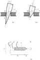
Figuren 3 bis 6 zeigen Einschraubsituationen von Schrauben mit unterschiedlich ausgeführten konusförmigen Spitzen. -
Figur 7 zeigt eine Ausführungsform einer erfindungsgemässen Fassadenplattenschraube. -
Figur 8 zeigt eine weitere Ausführungsform einer erfindungsgemässen Fassadenplattenschraube im verbauten Zustand in Seitenansicht / Teilquerschnitt. - Nachdem im Abschnitt "Beschreibung der Erfindung" bereits ausführlich auf die Zeichnungen 1-6 eingegangen wurde, seien hier nur die Kernbestandteile kurz erläutert.
- Die
Figuren 1 und 2 bezeichnen verschiedene Kenngrössen einer Befestigungsanordnung bzw. einer Fassadenplattenschraube. Mit S0 ist eine schematisierte, stark verkürzte Schraube gezeigt mit Durchmesser DS. Die Einbausituation in ein Bauteil B zeigt, dass die Schraube S0 um einen Winkel α gegenüber dem Lot N auf das Bauteil B verkippt ist. B hat eine vorgebohrtes Loch / Durchgangsöffnung O mit Durchmesser DB. K bzw. in späteren Figuren auch K' bezeichnen den Kontaktpunkt bzw. die Kontaktfläche oder Kontaktlinie zwischen der Schraube S und der Kante der Öffnung O im Bauteil B. - In
Figur 2 ist zusätzlich der Spitzenwinkel γ der Schraube S0 markiert. Da die Erfindung eine Schraube ohne Bohrspitze beschreibt, ist die Spitze mit geraden Flanken gemäss Stand der Technik ausgeführt. - Die
Figuren 4 bis 6 zeigen, wegen der Vergleichbarkeit schematisiert, Einschraubszenarien mit Schrauben S1 bis S4. Diese unterscheiden sich durch ihre Spitzengeometrie, wobei der Konuswinkel γ der Spitze von S1 nach S3 abnimmt. Der Kippwinkel α ist jeweils derselbe. Die Auswirkung der verschiedenen Berührungspunkte bzw. -flächen wurde oben erläutert. - In
Figur 7 ist eine erste Ausführungsform einer erfindungsgemässen Fassadenplattenschraube 10 gezeigt. Sie umfasst einen Kopf 12, dessen Durchmesser ein Mehrfaches des Schraubennenndurchmessers DS beträgt. Anschliessend an den Kopf befindet sich der Schaft 14, gefolgt von der konusförmigen Spitze 16. Der Schaft trägt ein Gewinde 18, erfindungsgemäss mindestens zweigängig, welches vom Schaft kontinuierlich auf den Konus bzw. die Spitze 16 übergeht. Unterkopfabschnitt 19 als Teil des Schaftes 14 ist gewindefrei ausgeführt. -
Figur 8 zeigt eine zweite Ausführungsform 30 einer erfindungsgemässen Fassadenplattenschraube. Sie weist bis auf den Anschlagbund 38 dieselben Funktionsgruppen auf. Der Kopf ist mit 32 bezeichnet, gefolgt von Schaft 34 und Spitze 36. Der Schaft trägt den Anschlagbund 38 zwischen dem Gewinde(abschnitt) und dem gewindefreien Unterkopfabschnitt 39. Die erfindungsgemässe Fassadenplattenschraube 30 ist verbaut in einer Befestigungsanordnung 20 gezeigt. Diese umfasst neben der Schraube 30 eine Fassadenplatte 22 und ein tragendes Bauteil 26. Letzteres ist oder ist Teil der Unterkonstruktion. Ferner ist eine Zwischenschicht 24 eingezeichnet, die als ein elastisches, dämpfendes Schaumstoffband ausgeführt sein kann. Zwischen der Fassadenplatte 22 und dem gewindefreien Unterkopfabschnitt 39 ist ein Freiraum vorgesehen, der der montierten Fassadenplatte 22 seitliches Spiel erlaubt, um unterschiedliche Ausdehnungen von der Unterkonstruktion 26 und der Fassadenplatte 22 auszugleichen und so einen Verzug der Fassade zu vermeiden. - Die in der vorstehenden Beschreibung, in den Zeichnungen sowie in den Ansprüchen offenbarten Merkmale der Erfindung können sowohl einzeln als auch in beliebiger, jedoch technisch sinnvoller bzw. vorteilhafter Kombination für die Verwirklichung der Erfindung wesentlich sein. Eine nicht-explizite Darstellung oder Beschreibung einer Kombination von Merkmalen bedeutet nicht, dass eine solche Kombination ausgeschlossen ist.
-
- S, S0, S1.... S4
- Schraube, Fassadenplattenschraube
- Z
- Rotations- bzw. zentrale Längsachse
- B
- Unterkonstruktion, Unterlage, Blech, metallisches Bauteil, Profil
- O
- Öffnung in B
- N
- Senkrechte, Lot auf B
- DB
- Durchmesser von O in B
- DS
- Durchmesser von S, S0...S4
- DK
- Kopfdurchmesser
- DP
- Durchmesser der Vorbohrungen in Fassadenplatte 22
- K, K'
- Kontaktpunkt(e)
- α
- Kippwinkel der Achse Z bezogen auf N
- β
- Winkel zwischen der Ebene von B und Konusflanke von S
- β'
- Winkel zwischen der Zylinderwand von O und Konusflanke von S
- γ
- Konuswinkel der Spitze von S, S0...S4
- 10, 30
- Fassadenplattenschraube
- 12, 32
- Kopf
- 14, 34
- Schaft
- 16, 36
- (konusförmige) Spitze der Schraube 10
- 18
- Gewinde, Gewindeabschnitt
- 19, 39
- gewindefreier Unterkopfabschnitt
- 38
- Bund, Anschlagbund
- 20
- Befestigungsanordnung
- 22
- Fassadenplatte
- 24
- Zwischenschicht
- 26
- tragendes Bauteil, Unterkonstruktion, Profil
- 28
- Spielraum
Claims (15)
- Fassadenplattenschraube (10) umfassend- einen Kopf (12) mit Durchmesser DK,- einen im wesentlichen zylinderquerschnittförmigen, längsausgedehnten Schaft (14) dessen Oberfläche zumindest teilweise mit einem Gewinde (18) versehen ist, mit einem Nenndurchmesser DS- und einer konusförmigen Spitze (16) mit einem Spitzenwinkel γ, wobei das Gewinde (18) sich vom Schaft (14) kontinuierlich bis auf die Spitze (16) erstreckt,
dadurch gekennzeichnet, dass- der Spitzenwinkel γ 45° +/-10° beträgt,- das Gewinde zumindest zweigängig ausgeführt ist,- der Kopfdurchmesser DK mindestens doppelt so gross ausgeführt ist wie der Nenndurchmesser DS; und- die Fassadenplattenschraube (10) keine Bohrspitze aufweist. - Fassadenplattenschraube (10) nach Anspruch 1, dadurch gekennzeichnet, dass die Fassadenplattenschraube einstückig gefertigt ist.
- Fassadenplattenschraube (10) nach Anspruch 1 und/oder2, dadurch gekennzeichnet, dass die Fassadenplattenschraube aus Edelstahl gefertigt ist.
- Fassadenplattenschraube (10) nach Anspruch 1 - 3, dadurch gekennzeichnet, dass die Fassadenplattenschraube eine dekorative, funktionelle bzw. korrosionshemmende Beschichtung aufweist.
- Fassadenplattenschraube (10, 30) nach Anspruch 1 - 4, dadurch gekennzeichnet, dass die Fassadenplattenschraube ferner einen gewindefreien Unterkopfabschnitt (19, 39) auf dem Schaft (14, 34) aufweist.
- Fassadenplattenschraube (30) nach Anspruch 1 - 5, dadurch gekennzeichnet, dass die Fassadenplattenschraube ferner einen Anschlagbund (38) aufweist, angeordnet auf dem Schaft (34) zwischen dem Gewinde und dem gewindefreien Unterkopfabschnitt (39).
- Fassadenplattenschraube (10, 30) nach Anspruch 1 - 6, dadurch gekennzeichnet, dass die Fassadenplattenschraube einen Nenndurchmesser von 4-7mm, bevorzugt 5-6mm (jeweils einschliesslich) aufweist.
- Fassadenplattenschraube (10, 30) nach Anspruch 1 - 4, dadurch gekennzeichnet, dass die Fassadenplattenschraube eine Steigung von 2 bis 3mm aufweist (jeweils einschliesslich)
- Befestigungsanordnung (20) umfassend ein tragendes Bauteil (26) und eine Fassadenplatte (22) sowie eine Fassadenplattenschraube (10, 30) nach Anspruch 1 - 8.
- Befestigungsanordnung (20) nach Anspruch 9, dadurch gekennzeichnet, dass das tragende Bauteil (26) Teil einer Unterkonstruktion ist und am Befestigungspunkt eine Materialstärke von 2 bis 6.5mm aus Aluminium bzw. 0.9 bis 2.5mm aus Stahl aufweist
- Befestigungsanordnung (20) nach Anspruch 9 und/oder 10, dadurch gekennzeichnet, dass die Fassadenplatte (26) aus Kunststoff, Metall, Faserzement, Isolationsmaterialien oder aus einem Verbund einer oder mehrerer solcher Materialien besteht.
- Befestigungsanordnung (20) nach Anspruch 9 - 11, dadurch gekennzeichnet, dass die Fassadenplatte (26) Vorbohrungen aufweist, deren Durchmesser DP mindestens 50% grösser sind als der Nenndurchmesser DS der Fassadenplattenschraube (10, 30).
- Befestigungsanordnung (20) nach Anspruch 9 - 12, dadurch gekennzeichnet, dass im tragenden Bauteil (26) bzw. der Unterkonstruktion Vorbohrungen vorgesehen sind, konzentrisch und fluchtend zu den Vorbohrungen in der Fassadenplatte und dass deren Durchmesser maximal 2mm grösser ist als der Nenndurchmesser DS der Fassadenplattenschraube (10, 30).
- Befestigungsanordnung (20) nach Anspruch 9 - 13, dadurch gekennzeichnet, dass zwischen dem tragenden Bauteil (26) und der Fassadenplatte (22) eine dämpfende, isolierende, reibungsmindernde und/oder klebende Zwischenschicht (24) angebracht ist.
- Befestigungsanordnung (20) nach Anspruch 14, dadurch gekennzeichnet, dass die Zwischenschicht (24) eine Schaumstoffband, ein Klebeband, ein Dämmfilz bzw. eine Kunststofflage ist.
Priority Applications (8)
| Application Number | Priority Date | Filing Date | Title |
|---|---|---|---|
| ES18160088T ES2957933T3 (es) | 2018-03-06 | 2018-03-06 | Tornillo de panel de fachada y disposición de fijación con el mismo |
| SI201831010T SI3536989T1 (sl) | 2018-03-06 | 2018-03-06 | Vijak za fasadno ploščo in pritrdilna razporeditev z le-tem |
| PT181600883T PT3536989T (pt) | 2018-03-06 | 2018-03-06 | Parafuso de painel de fachada e respetiva disposição de fixação |
| PL18160088.3T PL3536989T3 (pl) | 2018-03-06 | 2018-03-06 | Wkręt do płyt elewacyjnych oraz układ mocowania elewacji z takim wkrętem |
| FIEP18160088.3T FI3536989T3 (fi) | 2018-03-06 | 2018-03-06 | Julkisivulevyruuvi ja kiinnityskokoonpano |
| EP18160088.3A EP3536989B1 (de) | 2018-03-06 | 2018-03-06 | Fassadenplattenschraube und befestigungsanordnung hiermit |
| US15/928,456 US20190277325A1 (en) | 2018-03-06 | 2018-03-22 | Facade panel screw and fastening arrangement comprising same |
| US16/507,471 US11353053B2 (en) | 2018-03-06 | 2019-07-10 | Facade panel screw and fastening arrangement comprising same |
Applications Claiming Priority (1)
| Application Number | Priority Date | Filing Date | Title |
|---|---|---|---|
| EP18160088.3A EP3536989B1 (de) | 2018-03-06 | 2018-03-06 | Fassadenplattenschraube und befestigungsanordnung hiermit |
Publications (2)
| Publication Number | Publication Date |
|---|---|
| EP3536989A1 true EP3536989A1 (de) | 2019-09-11 |
| EP3536989B1 EP3536989B1 (de) | 2023-08-02 |
Family
ID=61569147
Family Applications (1)
| Application Number | Title | Priority Date | Filing Date |
|---|---|---|---|
| EP18160088.3A Active EP3536989B1 (de) | 2018-03-06 | 2018-03-06 | Fassadenplattenschraube und befestigungsanordnung hiermit |
Country Status (7)
| Country | Link |
|---|---|
| US (2) | US20190277325A1 (de) |
| EP (1) | EP3536989B1 (de) |
| ES (1) | ES2957933T3 (de) |
| FI (1) | FI3536989T3 (de) |
| PL (1) | PL3536989T3 (de) |
| PT (1) | PT3536989T (de) |
| SI (1) | SI3536989T1 (de) |
Cited By (2)
| Publication number | Priority date | Publication date | Assignee | Title |
|---|---|---|---|---|
| AT17203U1 (de) * | 2020-07-14 | 2021-09-15 | Dachdeckerei U Spenglerei Sajowitz Gmbh | Fassade sowie Verfahren zur Herstellung derselben |
| DE102024133953A1 (de) * | 2024-11-19 | 2026-05-21 | Adolf Würth GmbH & Co. KG | Schraube, Verfahren und Anordnung |
Families Citing this family (4)
| Publication number | Priority date | Publication date | Assignee | Title |
|---|---|---|---|---|
| US11959284B2 (en) * | 2021-07-21 | 2024-04-16 | C & H International Corporation | Siding splice joint |
| EP4187040A1 (de) * | 2021-11-29 | 2023-05-31 | Hilti Aktiengesellschaft | Plattenbefestigungssystem, fassade und verfahren zur befestigung von fassadenplatten an einem träger |
| USD1015134S1 (en) * | 2022-02-21 | 2024-02-20 | Jason D. Kerlin | Spool head thumb screw |
| DE102022206213A1 (de) | 2022-06-22 | 2023-12-28 | Ejot Se & Co. Kg | System und Verfahren zur beabstandeten Befestigung von Fassadenplatten |
Citations (7)
| Publication number | Priority date | Publication date | Assignee | Title |
|---|---|---|---|---|
| DE4239333A1 (de) * | 1992-11-23 | 1994-05-26 | Alfons Knoche | Schraube zum Befestigen von Fassadenplatten |
| DE9417276U1 (de) * | 1994-10-27 | 1994-12-15 | Berner GmbH, 74653 Künzelsau | Selbstschneidende Schraube |
| EP1182367A2 (de) * | 2000-08-26 | 2002-02-27 | Rathscheck Schiefer und Dach-Systeme KG | Schraube zur Befestigung von Platten und dergleichen |
| EP1582684A2 (de) * | 2004-03-29 | 2005-10-05 | SFS intec Holding AG | Schraube zur Verankerung eines mit einem Metallprofil verstärkten Kunststoffhohlprofils an einem Unterbau |
| DE102010040024A1 (de) * | 2010-08-31 | 2012-03-01 | Reisser Schraubentechnik Gmbh | Schraube |
| EP2574703A2 (de) * | 2011-09-27 | 2013-04-03 | RANIT-Befestigungssysteme GmbH | Befestigungssystem für Bauteile an einem tragenden Untergrund |
| DE202008018555U1 (de) * | 2007-03-15 | 2015-10-12 | Hilti Aktiengesellschaft | Spanlos gewindeformende Schraube |
Family Cites Families (14)
| Publication number | Priority date | Publication date | Assignee | Title |
|---|---|---|---|---|
| US1651796A (en) * | 1925-03-02 | 1927-12-06 | Internat Screw Company | Double-threaded screw |
| US2307348A (en) * | 1941-04-14 | 1943-01-05 | Anderson Chester Sig | Fastening device |
| US3965793A (en) * | 1971-12-08 | 1976-06-29 | Keystone Consolidated Industries, Inc. | Particleboard screw |
| US4194430A (en) * | 1978-05-05 | 1980-03-25 | Research Engineering & Manufacturing, Inc. | Thread-forming screw with step taper |
| FR2676244B1 (fr) * | 1991-05-07 | 1994-01-28 | Francis Ovaert | Structure composite, notamment pour le batiment. |
| DE4138555A1 (de) * | 1991-11-23 | 1993-05-27 | Hilti Ag | Schraube zum selbstschneidenden setzen |
| US5785478A (en) * | 1994-04-26 | 1998-07-28 | Rotter; Martin J. | Fastener |
| US5870870A (en) * | 1996-05-15 | 1999-02-16 | Utzman; Charles H. | Shear panel joint |
| US6457926B1 (en) * | 1999-12-06 | 2002-10-01 | Larry D. Pope | Screw with tapered formed bushing |
| US6994502B2 (en) * | 2002-08-14 | 2006-02-07 | Lifetime Products, Inc. | Pole joint screw for a basketball goal system |
| US20060140740A1 (en) * | 2004-12-29 | 2006-06-29 | Teng-Hung Lin | Screw with thread having different orientations |
| US20070183866A1 (en) * | 2006-02-09 | 2007-08-09 | Hangman Products, Inc. | Self locating wall fastener |
| US10995789B2 (en) * | 2017-09-06 | 2021-05-04 | Awi Licensing Llc | Multi-featured panel fastener and panel system including the multi-featured panel fastener |
| EP3578835B1 (de) * | 2018-06-04 | 2022-08-10 | SFS Group International AG | Fassadenplattenschraube und befestigungsanordnung hiermit |
-
2018
- 2018-03-06 FI FIEP18160088.3T patent/FI3536989T3/fi active
- 2018-03-06 PT PT181600883T patent/PT3536989T/pt unknown
- 2018-03-06 PL PL18160088.3T patent/PL3536989T3/pl unknown
- 2018-03-06 ES ES18160088T patent/ES2957933T3/es active Active
- 2018-03-06 SI SI201831010T patent/SI3536989T1/sl unknown
- 2018-03-06 EP EP18160088.3A patent/EP3536989B1/de active Active
- 2018-03-22 US US15/928,456 patent/US20190277325A1/en not_active Abandoned
-
2019
- 2019-07-10 US US16/507,471 patent/US11353053B2/en active Active
Patent Citations (7)
| Publication number | Priority date | Publication date | Assignee | Title |
|---|---|---|---|---|
| DE4239333A1 (de) * | 1992-11-23 | 1994-05-26 | Alfons Knoche | Schraube zum Befestigen von Fassadenplatten |
| DE9417276U1 (de) * | 1994-10-27 | 1994-12-15 | Berner GmbH, 74653 Künzelsau | Selbstschneidende Schraube |
| EP1182367A2 (de) * | 2000-08-26 | 2002-02-27 | Rathscheck Schiefer und Dach-Systeme KG | Schraube zur Befestigung von Platten und dergleichen |
| EP1582684A2 (de) * | 2004-03-29 | 2005-10-05 | SFS intec Holding AG | Schraube zur Verankerung eines mit einem Metallprofil verstärkten Kunststoffhohlprofils an einem Unterbau |
| DE202008018555U1 (de) * | 2007-03-15 | 2015-10-12 | Hilti Aktiengesellschaft | Spanlos gewindeformende Schraube |
| DE102010040024A1 (de) * | 2010-08-31 | 2012-03-01 | Reisser Schraubentechnik Gmbh | Schraube |
| EP2574703A2 (de) * | 2011-09-27 | 2013-04-03 | RANIT-Befestigungssysteme GmbH | Befestigungssystem für Bauteile an einem tragenden Untergrund |
Cited By (3)
| Publication number | Priority date | Publication date | Assignee | Title |
|---|---|---|---|---|
| AT17203U1 (de) * | 2020-07-14 | 2021-09-15 | Dachdeckerei U Spenglerei Sajowitz Gmbh | Fassade sowie Verfahren zur Herstellung derselben |
| EP3940166A1 (de) * | 2020-07-14 | 2022-01-19 | Dachdeckerei u. Spenglerei Sajowitz GmbH | Fassade sowie verfahren zur herstellung derselben |
| DE102024133953A1 (de) * | 2024-11-19 | 2026-05-21 | Adolf Würth GmbH & Co. KG | Schraube, Verfahren und Anordnung |
Also Published As
| Publication number | Publication date |
|---|---|
| SI3536989T1 (sl) | 2023-12-29 |
| PT3536989T (pt) | 2023-09-26 |
| US20190331151A1 (en) | 2019-10-31 |
| PL3536989T3 (pl) | 2023-10-02 |
| FI3536989T3 (fi) | 2023-09-14 |
| US20190277325A1 (en) | 2019-09-12 |
| ES2957933T3 (es) | 2024-01-30 |
| US11353053B2 (en) | 2022-06-07 |
| EP3536989B1 (de) | 2023-08-02 |
Similar Documents
| Publication | Publication Date | Title |
|---|---|---|
| EP3536989B1 (de) | Fassadenplattenschraube und befestigungsanordnung hiermit | |
| EP3578835B1 (de) | Fassadenplattenschraube und befestigungsanordnung hiermit | |
| AT409988B (de) | Verfahren zum befestigen von holzkonstruktionsteilen vor einer betonwand oder mauer | |
| EP3415773B1 (de) | Schraube mit einem mehrgängigen unterkopfgewinde und befestigungsanordnung hierzu | |
| EP3199824B1 (de) | Befestigungsanordnung und verwendung einer befestigungsanordnung | |
| DE102012215645B4 (de) | Schraube und ihre Verwendung | |
| DE202019001906U1 (de) | Einschraubdübel | |
| EP2491258B1 (de) | Bohrschraube | |
| EP4234959A1 (de) | Schraube mit im gewinde eingebettetem fräsabschnitt | |
| DE3333055C2 (de) | Vorrichtung zum Befestigen von Latten | |
| DE102010045445A1 (de) | Montagesystem für Isolierstoffplatten | |
| DE19831269C2 (de) | Fensterbauschraube | |
| DE102014000894A1 (de) | Verfahren zum Herstellen einer Befestigungsanordnung, Befestigungsanordnung und dafür vorgesehene Schraube | |
| DE29811036U1 (de) | Schraube zur Abstandsbefestigung von Abdeckplatten oder Schienen an einem Unterbau | |
| DE3043478A1 (de) | Selbstbohrende schraube | |
| EP1034379A1 (de) | Schraube zur abstandsbefestigung von abdeckplatten oder schienen an einem unterbau | |
| DE102004038031A1 (de) | Befestigungseinrichtung für Wärmedämm-Verbundsysteme | |
| DE3107403A1 (de) | "schraubnagel" | |
| WO2011042200A1 (de) | Beschlag zum einstellen eines abstandes zwischen einem bauelement und einem unterbau sowie ein system und verfahren hierfür | |
| EP3421821B1 (de) | Dübel, anordnung mit einem dübel und verwendung eines dübels | |
| DE102006002532A1 (de) | Selbstbohrende Schraube | |
| DE202025000892U1 (de) | Schraube für die Montage von Sandwichpanelen auf einer tragenden Unterkonstruktion aus Holz | |
| WO2016096570A1 (de) | Schraube und konstruktion | |
| DE102025121905A1 (de) | Schraube, insbesondere Distanzschraube | |
| EP4686835A1 (de) | Schraube, insbesondere distanzschraube |
Legal Events
| Date | Code | Title | Description |
|---|---|---|---|
| PUAI | Public reference made under article 153(3) epc to a published international application that has entered the european phase |
Free format text: ORIGINAL CODE: 0009012 |
|
| STAA | Information on the status of an ep patent application or granted ep patent |
Free format text: STATUS: THE APPLICATION HAS BEEN PUBLISHED |
|
| AK | Designated contracting states |
Kind code of ref document: A1 Designated state(s): AL AT BE BG CH CY CZ DE DK EE ES FI FR GB GR HR HU IE IS IT LI LT LU LV MC MK MT NL NO PL PT RO RS SE SI SK SM TR |
|
| AX | Request for extension of the european patent |
Extension state: BA ME |
|
| STAA | Information on the status of an ep patent application or granted ep patent |
Free format text: STATUS: REQUEST FOR EXAMINATION WAS MADE |
|
| 17P | Request for examination filed |
Effective date: 20200311 |
|
| RBV | Designated contracting states (corrected) |
Designated state(s): AL AT BE BG CH CY CZ DE DK EE ES FI FR GB GR HR HU IE IS IT LI LT LU LV MC MK MT NL NO PL PT RO RS SE SI SK SM TR |
|
| STAA | Information on the status of an ep patent application or granted ep patent |
Free format text: STATUS: EXAMINATION IS IN PROGRESS |
|
| 17Q | First examination report despatched |
Effective date: 20210713 |
|
| RAP3 | Party data changed (applicant data changed or rights of an application transferred) |
Owner name: SFS GROUP INTERNATIONAL AG |
|
| GRAP | Despatch of communication of intention to grant a patent |
Free format text: ORIGINAL CODE: EPIDOSNIGR1 |
|
| STAA | Information on the status of an ep patent application or granted ep patent |
Free format text: STATUS: GRANT OF PATENT IS INTENDED |
|
| INTG | Intention to grant announced |
Effective date: 20230418 |
|
| GRAS | Grant fee paid |
Free format text: ORIGINAL CODE: EPIDOSNIGR3 |
|
| GRAA | (expected) grant |
Free format text: ORIGINAL CODE: 0009210 |
|
| STAA | Information on the status of an ep patent application or granted ep patent |
Free format text: STATUS: THE PATENT HAS BEEN GRANTED |
|
| AK | Designated contracting states |
Kind code of ref document: B1 Designated state(s): AL AT BE BG CH CY CZ DE DK EE ES FI FR GB GR HR HU IE IS IT LI LT LU LV MC MK MT NL NO PL PT RO RS SE SI SK SM TR |
|
| REG | Reference to a national code |
Ref country code: GB Ref legal event code: FG4D Free format text: NOT ENGLISH |
|
| REG | Reference to a national code |
Ref country code: CH Ref legal event code: EP |
|
| REG | Reference to a national code |
Ref country code: DE Ref legal event code: R096 Ref document number: 502018012825 Country of ref document: DE |
|
| REG | Reference to a national code |
Ref country code: IE Ref legal event code: FG4D Free format text: LANGUAGE OF EP DOCUMENT: GERMAN |
|
| REG | Reference to a national code |
Ref country code: FI Ref legal event code: FGE |
|
| REG | Reference to a national code |
Ref country code: PT Ref legal event code: SC4A Ref document number: 3536989 Country of ref document: PT Date of ref document: 20230926 Kind code of ref document: T Free format text: AVAILABILITY OF NATIONAL TRANSLATION Effective date: 20230919 |
|
| REG | Reference to a national code |
Ref country code: NL Ref legal event code: FP |
|
| REG | Reference to a national code |
Ref country code: NO Ref legal event code: T2 Effective date: 20230802 |
|
| REG | Reference to a national code |
Ref country code: SE Ref legal event code: TRGR |
|
| REG | Reference to a national code |
Ref country code: EE Ref legal event code: FG4A Ref document number: E023592 Country of ref document: EE Effective date: 20230912 |
|
| REG | Reference to a national code |
Ref country code: LT Ref legal event code: MG9D |
|
| REG | Reference to a national code |
Ref country code: SK Ref legal event code: T3 Ref document number: E 42395 Country of ref document: SK |
|
| PG25 | Lapsed in a contracting state [announced via postgrant information from national office to epo] |
Ref country code: GR Free format text: LAPSE BECAUSE OF FAILURE TO SUBMIT A TRANSLATION OF THE DESCRIPTION OR TO PAY THE FEE WITHIN THE PRESCRIBED TIME-LIMIT Effective date: 20231103 |
|
| PG25 | Lapsed in a contracting state [announced via postgrant information from national office to epo] |
Ref country code: IS Free format text: LAPSE BECAUSE OF FAILURE TO SUBMIT A TRANSLATION OF THE DESCRIPTION OR TO PAY THE FEE WITHIN THE PRESCRIBED TIME-LIMIT Effective date: 20231202 |
|
| REG | Reference to a national code |
Ref country code: ES Ref legal event code: FG2A Ref document number: 2957933 Country of ref document: ES Kind code of ref document: T3 Effective date: 20240130 |
|
| PG25 | Lapsed in a contracting state [announced via postgrant information from national office to epo] |
Ref country code: RS Free format text: LAPSE BECAUSE OF FAILURE TO SUBMIT A TRANSLATION OF THE DESCRIPTION OR TO PAY THE FEE WITHIN THE PRESCRIBED TIME-LIMIT Effective date: 20230802 Ref country code: LV Free format text: LAPSE BECAUSE OF FAILURE TO SUBMIT A TRANSLATION OF THE DESCRIPTION OR TO PAY THE FEE WITHIN THE PRESCRIBED TIME-LIMIT Effective date: 20230802 Ref country code: LT Free format text: LAPSE BECAUSE OF FAILURE TO SUBMIT A TRANSLATION OF THE DESCRIPTION OR TO PAY THE FEE WITHIN THE PRESCRIBED TIME-LIMIT Effective date: 20230802 Ref country code: IS Free format text: LAPSE BECAUSE OF FAILURE TO SUBMIT A TRANSLATION OF THE DESCRIPTION OR TO PAY THE FEE WITHIN THE PRESCRIBED TIME-LIMIT Effective date: 20231202 Ref country code: HR Free format text: LAPSE BECAUSE OF FAILURE TO SUBMIT A TRANSLATION OF THE DESCRIPTION OR TO PAY THE FEE WITHIN THE PRESCRIBED TIME-LIMIT Effective date: 20230802 Ref country code: GR Free format text: LAPSE BECAUSE OF FAILURE TO SUBMIT A TRANSLATION OF THE DESCRIPTION OR TO PAY THE FEE WITHIN THE PRESCRIBED TIME-LIMIT Effective date: 20231103 |
|
| PG25 | Lapsed in a contracting state [announced via postgrant information from national office to epo] |
Ref country code: SM Free format text: LAPSE BECAUSE OF FAILURE TO SUBMIT A TRANSLATION OF THE DESCRIPTION OR TO PAY THE FEE WITHIN THE PRESCRIBED TIME-LIMIT Effective date: 20230802 Ref country code: RO Free format text: LAPSE BECAUSE OF FAILURE TO SUBMIT A TRANSLATION OF THE DESCRIPTION OR TO PAY THE FEE WITHIN THE PRESCRIBED TIME-LIMIT Effective date: 20230802 Ref country code: DK Free format text: LAPSE BECAUSE OF FAILURE TO SUBMIT A TRANSLATION OF THE DESCRIPTION OR TO PAY THE FEE WITHIN THE PRESCRIBED TIME-LIMIT Effective date: 20230802 |
|
| REG | Reference to a national code |
Ref country code: DE Ref legal event code: R097 Ref document number: 502018012825 Country of ref document: DE |
|
| PLBE | No opposition filed within time limit |
Free format text: ORIGINAL CODE: 0009261 |
|
| STAA | Information on the status of an ep patent application or granted ep patent |
Free format text: STATUS: NO OPPOSITION FILED WITHIN TIME LIMIT |
|
| 26N | No opposition filed |
Effective date: 20240503 |
|
| PG25 | Lapsed in a contracting state [announced via postgrant information from national office to epo] |
Ref country code: BG Free format text: LAPSE BECAUSE OF FAILURE TO SUBMIT A TRANSLATION OF THE DESCRIPTION OR TO PAY THE FEE WITHIN THE PRESCRIBED TIME-LIMIT Effective date: 20230802 |
|
| PG25 | Lapsed in a contracting state [announced via postgrant information from national office to epo] |
Ref country code: MC Free format text: LAPSE BECAUSE OF FAILURE TO SUBMIT A TRANSLATION OF THE DESCRIPTION OR TO PAY THE FEE WITHIN THE PRESCRIBED TIME-LIMIT Effective date: 20230802 |
|
| PG25 | Lapsed in a contracting state [announced via postgrant information from national office to epo] |
Ref country code: MC Free format text: LAPSE BECAUSE OF FAILURE TO SUBMIT A TRANSLATION OF THE DESCRIPTION OR TO PAY THE FEE WITHIN THE PRESCRIBED TIME-LIMIT Effective date: 20230802 Ref country code: BG Free format text: LAPSE BECAUSE OF FAILURE TO SUBMIT A TRANSLATION OF THE DESCRIPTION OR TO PAY THE FEE WITHIN THE PRESCRIBED TIME-LIMIT Effective date: 20230802 |
|
| PG25 | Lapsed in a contracting state [announced via postgrant information from national office to epo] |
Ref country code: IE Free format text: LAPSE BECAUSE OF NON-PAYMENT OF DUE FEES Effective date: 20240306 |
|
| PG25 | Lapsed in a contracting state [announced via postgrant information from national office to epo] |
Ref country code: IE Free format text: LAPSE BECAUSE OF NON-PAYMENT OF DUE FEES Effective date: 20240306 |
|
| PGFP | Annual fee paid to national office [announced via postgrant information from national office to epo] |
Ref country code: ES Payment date: 20250416 Year of fee payment: 8 |
|
| PGFP | Annual fee paid to national office [announced via postgrant information from national office to epo] |
Ref country code: IT Payment date: 20250331 Year of fee payment: 8 |
|
| PGFP | Annual fee paid to national office [announced via postgrant information from national office to epo] |
Ref country code: CH Payment date: 20250401 Year of fee payment: 8 |
|
| PG25 | Lapsed in a contracting state [announced via postgrant information from national office to epo] |
Ref country code: CY Free format text: LAPSE BECAUSE OF FAILURE TO SUBMIT A TRANSLATION OF THE DESCRIPTION OR TO PAY THE FEE WITHIN THE PRESCRIBED TIME-LIMIT; INVALID AB INITIO Effective date: 20180306 |
|
| PG25 | Lapsed in a contracting state [announced via postgrant information from national office to epo] |
Ref country code: HU Free format text: LAPSE BECAUSE OF FAILURE TO SUBMIT A TRANSLATION OF THE DESCRIPTION OR TO PAY THE FEE WITHIN THE PRESCRIBED TIME-LIMIT; INVALID AB INITIO Effective date: 20180306 |
|
| PG25 | Lapsed in a contracting state [announced via postgrant information from national office to epo] |
Ref country code: TR Free format text: LAPSE BECAUSE OF FAILURE TO SUBMIT A TRANSLATION OF THE DESCRIPTION OR TO PAY THE FEE WITHIN THE PRESCRIBED TIME-LIMIT Effective date: 20230802 |
|
| REG | Reference to a national code |
Ref country code: CH Ref legal event code: U11 Free format text: ST27 STATUS EVENT CODE: U-0-0-U10-U11 (AS PROVIDED BY THE NATIONAL OFFICE) Effective date: 20260401 |
|
| PGFP | Annual fee paid to national office [announced via postgrant information from national office to epo] |
Ref country code: SE Payment date: 20260323 Year of fee payment: 9 |
|
| PGFP | Annual fee paid to national office [announced via postgrant information from national office to epo] |
Ref country code: GB Payment date: 20260324 Year of fee payment: 9 |
|
| PGFP | Annual fee paid to national office [announced via postgrant information from national office to epo] |
Ref country code: DE Payment date: 20260320 Year of fee payment: 9 Ref country code: NO Payment date: 20260320 Year of fee payment: 9 |
|
| PGFP | Annual fee paid to national office [announced via postgrant information from national office to epo] |
Ref country code: AT Payment date: 20260319 Year of fee payment: 9 |
|
| PGFP | Annual fee paid to national office [announced via postgrant information from national office to epo] |
Ref country code: LU Payment date: 20260320 Year of fee payment: 9 Ref country code: FI Payment date: 20260320 Year of fee payment: 9 Ref country code: BE Payment date: 20260323 Year of fee payment: 9 |
|
| PGFP | Annual fee paid to national office [announced via postgrant information from national office to epo] |
Ref country code: NL Payment date: 20260323 Year of fee payment: 9 |
|
| PGFP | Annual fee paid to national office [announced via postgrant information from national office to epo] |
Ref country code: FR Payment date: 20260324 Year of fee payment: 9 |
|
| PGFP | Annual fee paid to national office [announced via postgrant information from national office to epo] |
Ref country code: PT Payment date: 20260226 Year of fee payment: 9 Ref country code: CZ Payment date: 20260226 Year of fee payment: 9 |
|
| PGFP | Annual fee paid to national office [announced via postgrant information from national office to epo] |
Ref country code: PL Payment date: 20260302 Year of fee payment: 9 |
|
| PGFP | Annual fee paid to national office [announced via postgrant information from national office to epo] |
Ref country code: SK Payment date: 20260305 Year of fee payment: 9 Ref country code: EE Payment date: 20260323 Year of fee payment: 9 |
|
| PGFP | Annual fee paid to national office [announced via postgrant information from national office to epo] |
Ref country code: SI Payment date: 20260226 Year of fee payment: 9 |