EP3536635A1 - Aufbewahrungseinheit für schweissdraht - Google Patents
Aufbewahrungseinheit für schweissdraht Download PDFInfo
- Publication number
- EP3536635A1 EP3536635A1 EP19159282.3A EP19159282A EP3536635A1 EP 3536635 A1 EP3536635 A1 EP 3536635A1 EP 19159282 A EP19159282 A EP 19159282A EP 3536635 A1 EP3536635 A1 EP 3536635A1
- Authority
- EP
- European Patent Office
- Prior art keywords
- storage unit
- outer case
- strap
- welding wire
- corrugated cardboard
- Prior art date
- Legal status (The legal status is an assumption and is not a legal conclusion. Google has not performed a legal analysis and makes no representation as to the accuracy of the status listed.)
- Granted
Links
Images






Classifications
-
- B—PERFORMING OPERATIONS; TRANSPORTING
- B65—CONVEYING; PACKING; STORING; HANDLING THIN OR FILAMENTARY MATERIAL
- B65D—CONTAINERS FOR STORAGE OR TRANSPORT OF ARTICLES OR MATERIALS, e.g. BAGS, BARRELS, BOTTLES, BOXES, CANS, CARTONS, CRATES, DRUMS, JARS, TANKS, HOPPERS, FORWARDING CONTAINERS; ACCESSORIES, CLOSURES, OR FITTINGS THEREFOR; PACKAGING ELEMENTS; PACKAGES
- B65D5/00—Rigid or semi-rigid containers of polygonal cross-section, e.g. boxes, cartons or trays, formed by folding or erecting one or more blanks made of paper
- B65D5/42—Details of containers or of foldable or erectable container blanks
- B65D5/44—Integral, inserted or attached portions forming internal or external fittings
- B65D5/441—Reinforcements
-
- B—PERFORMING OPERATIONS; TRANSPORTING
- B65—CONVEYING; PACKING; STORING; HANDLING THIN OR FILAMENTARY MATERIAL
- B65D—CONTAINERS FOR STORAGE OR TRANSPORT OF ARTICLES OR MATERIALS, e.g. BAGS, BARRELS, BOTTLES, BOXES, CANS, CARTONS, CRATES, DRUMS, JARS, TANKS, HOPPERS, FORWARDING CONTAINERS; ACCESSORIES, CLOSURES, OR FITTINGS THEREFOR; PACKAGING ELEMENTS; PACKAGES
- B65D85/00—Containers, packaging elements or packages, specially adapted for particular articles or materials
- B65D85/02—Containers, packaging elements or packages, specially adapted for particular articles or materials for annular articles
-
- B—PERFORMING OPERATIONS; TRANSPORTING
- B65—CONVEYING; PACKING; STORING; HANDLING THIN OR FILAMENTARY MATERIAL
- B65D—CONTAINERS FOR STORAGE OR TRANSPORT OF ARTICLES OR MATERIALS, e.g. BAGS, BARRELS, BOTTLES, BOXES, CANS, CARTONS, CRATES, DRUMS, JARS, TANKS, HOPPERS, FORWARDING CONTAINERS; ACCESSORIES, CLOSURES, OR FITTINGS THEREFOR; PACKAGING ELEMENTS; PACKAGES
- B65D25/00—Details of other kinds or types of rigid or semi-rigid containers
- B65D25/20—External fittings
- B65D25/22—External fittings for facilitating lifting or suspending of containers
-
- B—PERFORMING OPERATIONS; TRANSPORTING
- B65—CONVEYING; PACKING; STORING; HANDLING THIN OR FILAMENTARY MATERIAL
- B65D—CONTAINERS FOR STORAGE OR TRANSPORT OF ARTICLES OR MATERIALS, e.g. BAGS, BARRELS, BOTTLES, BOXES, CANS, CARTONS, CRATES, DRUMS, JARS, TANKS, HOPPERS, FORWARDING CONTAINERS; ACCESSORIES, CLOSURES, OR FITTINGS THEREFOR; PACKAGING ELEMENTS; PACKAGES
- B65D25/00—Details of other kinds or types of rigid or semi-rigid containers
- B65D25/34—Coverings or external coatings
-
- B—PERFORMING OPERATIONS; TRANSPORTING
- B65—CONVEYING; PACKING; STORING; HANDLING THIN OR FILAMENTARY MATERIAL
- B65D—CONTAINERS FOR STORAGE OR TRANSPORT OF ARTICLES OR MATERIALS, e.g. BAGS, BARRELS, BOTTLES, BOXES, CANS, CARTONS, CRATES, DRUMS, JARS, TANKS, HOPPERS, FORWARDING CONTAINERS; ACCESSORIES, CLOSURES, OR FITTINGS THEREFOR; PACKAGING ELEMENTS; PACKAGES
- B65D5/00—Rigid or semi-rigid containers of polygonal cross-section, e.g. boxes, cartons or trays, formed by folding or erecting one or more blanks made of paper
- B65D5/02—Rigid or semi-rigid containers of polygonal cross-section, e.g. boxes, cartons or trays, formed by folding or erecting one or more blanks made of paper by folding or erecting a single blank to form a tubular body with or without subsequent folding operations, or the addition of separate elements, to close the ends of the body
- B65D5/12—Rigid or semi-rigid containers of polygonal cross-section, e.g. boxes, cartons or trays, formed by folding or erecting one or more blanks made of paper by folding or erecting a single blank to form a tubular body with or without subsequent folding operations, or the addition of separate elements, to close the ends of the body with end closures formed separately from tubular body
-
- B—PERFORMING OPERATIONS; TRANSPORTING
- B65—CONVEYING; PACKING; STORING; HANDLING THIN OR FILAMENTARY MATERIAL
- B65D—CONTAINERS FOR STORAGE OR TRANSPORT OF ARTICLES OR MATERIALS, e.g. BAGS, BARRELS, BOTTLES, BOXES, CANS, CARTONS, CRATES, DRUMS, JARS, TANKS, HOPPERS, FORWARDING CONTAINERS; ACCESSORIES, CLOSURES, OR FITTINGS THEREFOR; PACKAGING ELEMENTS; PACKAGES
- B65D5/00—Rigid or semi-rigid containers of polygonal cross-section, e.g. boxes, cartons or trays, formed by folding or erecting one or more blanks made of paper
- B65D5/42—Details of containers or of foldable or erectable container blanks
- B65D5/44—Integral, inserted or attached portions forming internal or external fittings
- B65D5/46—Handles
- B65D5/46008—Handles formed separately from the container body
- B65D5/46024—Straps used as handles with anchoring elements fixed in slots
-
- B—PERFORMING OPERATIONS; TRANSPORTING
- B65—CONVEYING; PACKING; STORING; HANDLING THIN OR FILAMENTARY MATERIAL
- B65D—CONTAINERS FOR STORAGE OR TRANSPORT OF ARTICLES OR MATERIALS, e.g. BAGS, BARRELS, BOTTLES, BOXES, CANS, CARTONS, CRATES, DRUMS, JARS, TANKS, HOPPERS, FORWARDING CONTAINERS; ACCESSORIES, CLOSURES, OR FITTINGS THEREFOR; PACKAGING ELEMENTS; PACKAGES
- B65D5/00—Rigid or semi-rigid containers of polygonal cross-section, e.g. boxes, cartons or trays, formed by folding or erecting one or more blanks made of paper
- B65D5/42—Details of containers or of foldable or erectable container blanks
- B65D5/44—Integral, inserted or attached portions forming internal or external fittings
- B65D5/50—Internal supporting or protecting elements for contents
- B65D5/5028—Elements formed separately from the container body
-
- B—PERFORMING OPERATIONS; TRANSPORTING
- B65—CONVEYING; PACKING; STORING; HANDLING THIN OR FILAMENTARY MATERIAL
- B65D—CONTAINERS FOR STORAGE OR TRANSPORT OF ARTICLES OR MATERIALS, e.g. BAGS, BARRELS, BOTTLES, BOXES, CANS, CARTONS, CRATES, DRUMS, JARS, TANKS, HOPPERS, FORWARDING CONTAINERS; ACCESSORIES, CLOSURES, OR FITTINGS THEREFOR; PACKAGING ELEMENTS; PACKAGES
- B65D5/00—Rigid or semi-rigid containers of polygonal cross-section, e.g. boxes, cartons or trays, formed by folding or erecting one or more blanks made of paper
- B65D5/42—Details of containers or of foldable or erectable container blanks
- B65D5/56—Linings or internal coatings, e.g. pre-formed trays provided with a blow- or thermoformed layer
- B65D5/60—Loose, or loosely attached, linings
-
- B—PERFORMING OPERATIONS; TRANSPORTING
- B65—CONVEYING; PACKING; STORING; HANDLING THIN OR FILAMENTARY MATERIAL
- B65D—CONTAINERS FOR STORAGE OR TRANSPORT OF ARTICLES OR MATERIALS, e.g. BAGS, BARRELS, BOTTLES, BOXES, CANS, CARTONS, CRATES, DRUMS, JARS, TANKS, HOPPERS, FORWARDING CONTAINERS; ACCESSORIES, CLOSURES, OR FITTINGS THEREFOR; PACKAGING ELEMENTS; PACKAGES
- B65D5/00—Rigid or semi-rigid containers of polygonal cross-section, e.g. boxes, cartons or trays, formed by folding or erecting one or more blanks made of paper
- B65D5/42—Details of containers or of foldable or erectable container blanks
- B65D5/64—Lids
-
- B—PERFORMING OPERATIONS; TRANSPORTING
- B65—CONVEYING; PACKING; STORING; HANDLING THIN OR FILAMENTARY MATERIAL
- B65D—CONTAINERS FOR STORAGE OR TRANSPORT OF ARTICLES OR MATERIALS, e.g. BAGS, BARRELS, BOTTLES, BOXES, CANS, CARTONS, CRATES, DRUMS, JARS, TANKS, HOPPERS, FORWARDING CONTAINERS; ACCESSORIES, CLOSURES, OR FITTINGS THEREFOR; PACKAGING ELEMENTS; PACKAGES
- B65D81/00—Containers, packaging elements, or packages, for contents presenting particular transport or storage problems, or adapted to be used for non-packaging purposes after removal of contents
- B65D81/02—Containers, packaging elements, or packages, for contents presenting particular transport or storage problems, or adapted to be used for non-packaging purposes after removal of contents specially adapted to protect contents from mechanical damage
- B65D81/025—Containers made of sheet-like material and having a shape to accommodate contents
- B65D81/027—Containers made of sheet-like material and having a shape to accommodate contents double-walled
-
- B—PERFORMING OPERATIONS; TRANSPORTING
- B65—CONVEYING; PACKING; STORING; HANDLING THIN OR FILAMENTARY MATERIAL
- B65D—CONTAINERS FOR STORAGE OR TRANSPORT OF ARTICLES OR MATERIALS, e.g. BAGS, BARRELS, BOTTLES, BOXES, CANS, CARTONS, CRATES, DRUMS, JARS, TANKS, HOPPERS, FORWARDING CONTAINERS; ACCESSORIES, CLOSURES, OR FITTINGS THEREFOR; PACKAGING ELEMENTS; PACKAGES
- B65D85/00—Containers, packaging elements or packages, specially adapted for particular articles or materials
- B65D85/02—Containers, packaging elements or packages, specially adapted for particular articles or materials for annular articles
- B65D85/04—Containers, packaging elements or packages, specially adapted for particular articles or materials for annular articles for coils of wire, rope or hose
-
- Y—GENERAL TAGGING OF NEW TECHNOLOGICAL DEVELOPMENTS; GENERAL TAGGING OF CROSS-SECTIONAL TECHNOLOGIES SPANNING OVER SEVERAL SECTIONS OF THE IPC; TECHNICAL SUBJECTS COVERED BY FORMER USPC CROSS-REFERENCE ART COLLECTIONS [XRACs] AND DIGESTS
- Y02—TECHNOLOGIES OR APPLICATIONS FOR MITIGATION OR ADAPTATION AGAINST CLIMATE CHANGE
- Y02W—CLIMATE CHANGE MITIGATION TECHNOLOGIES RELATED TO WASTEWATER TREATMENT OR WASTE MANAGEMENT
- Y02W30/00—Technologies for solid waste management
- Y02W30/50—Reuse, recycling or recovery technologies
- Y02W30/80—Packaging reuse or recycling, e.g. of multilayer packaging
Definitions
- the present disclosure relates to a storage unit for welding wire, and more specifically, to a storage unit for welding wire which is easily recycled and durable against an external impact and a buckling load, and includes a strap guide and thus is easily carried.
- a welding wire is stored in a coil shape in a case body, an inner surface of a case body is covered by a resin, and a metallic cover is covered on an opening of an upper end of the case body, and a boundary between the case body and the cover is sealed with a sealing member such as rubber or the like. Further, in the case body of the storage unit, a lower end portion and an upper end portion which require strength are reinforced by a ring-shaped metal member.
- the storage unit can be repeatedly used to store the welding wire after use, but generally is discarded after being used a predetermined number of times.
- the ring-shaped metal member and the cover which are made of metal have to be separated from the case body. Otherwise, the ring-shaped metal member and the cover are not separated and all of the above are processed as industrial waste. Accordingly, a conventional storage unit has a complicated recycling process and is not eco-friendly.
- the storage unit made of paper is weak against an external impact in comparison with the conventional storage unit. Further, when storage units are stacked in two layers in a state in which welding wires are stored, a buckling load applied to a lower storage unit from an upper storage unit should be overcome.
- an opening can be formed in a side portion of the storage unit to allow the storage unit to be easily moved, and in the case of the storage unit made of paper, the opening of the storage unit is easily worn and damaged when a process such as lifting or moving the storage unit using a strap is repeated over and over.
- the method should be performed by hand and a large amount of time is consumed.
- Patent Document 1 Japanese Laid-Open Patent No. 2001-301886 (October 31,2001 )
- the present disclosure is directed to providing a storage unit for welding wire which is easily recycled and durable against an external impact and a buckling load, and includes a strap guide and thus is easily carried.
- a storage unit for welding wire including: an outer case in which an outer bottom supporting part is formed in a lower end thereof and a wire accommodation part configured to accommodate a wound welding wire is formed therein; a bottom part seated on and coupled to the outer bottom supporting part; and an inner case configured to come into close contact with an inner surface of the outer case and having an inner bottom supporting part seated on the bottom part, formed in a lower portion thereof, wherein the outer case includes a strength reinforcement part and a shock absorption part formed at an inner side of the strength reinforcement part to absorb a shock from the outside.
- the strength reinforcement part may include a first cardboard and a first corrugated cardboard
- the shock absorption part may include a second cardboard and a second corrugated cardboard
- the number of corrugations of the first corrugated cardboard may be greater than the number of corrugations of the second corrugated cardboard
- the outer case may further include two or more accommodation space parts each configured to accommodate a strap guide in a side portion.
- the strap guide may be coupled to the accommodation space part, and the strap guide may include: a first module including a first base, a strap boss formed on the first base and including a first slot through which a strap passes, and at least one protrusion accommodation part located at an outer circumferential portion of the strap boss and including a bore; and a second module including a second base, a second slot formed in the second base, and at least one coupling protrusion located at an outer circumferential portion of the second slot and formed to form a pair with the protrusion accommodation part, wherein the first module and the second module are coupled to form an opening having a single closed surface.
- an edge of the opening may have a gentle round shape.
- the second base may further include a bent portion having an inclination angle and inclined toward the outside.
- the accommodation space part may include a center space part into which the strap boss is fitted, and an upper space part and a lower space part into which the protrusion accommodation part is fitted, and the strap guide may be fitted into the accommodation space part
- the first module may be disposed in an interspace part between the outer case and the inner case and the second module may pass through the accommodation space part formed in an outer surface of the outer case from the outer side of the outer case to be coupled to the first module.
- a height of the strap boss may be greater than or equal to a thickness of the outer case
- the storage unit may further include a strap having a center portion disposed between the outer bottom supporting part and the bottom part and both end portions disposed in the interspace part between the outer case and the inner case, and exposed to an accommodation space part formed to face an outer surface of the outer case to form engaging portions.
- the inner case may further include at least one cut portion.
- FIG. 1 is a perspective view illustrating an appearance of a storage unit 1000 for welding wire according to an embodiment of the present disclosure. Further, the storage unit 1000 for welding wire of the present disclosure may be formed of paper.
- the appearance of the storage unit 1000 for welding wire may be formed by an outer case 100 and a cap 600.
- the outer case 100 may have a polygonal pillar shape and may preferably have a cross-section having a regular dodecagon shape.
- An upper portion of the outer case 100 is formed to be open to the outside.
- the cap 600 may have a polygonal pillar shape corresponding to the shape of the outer case 100 having an inner space portion.
- the cap 600 serves to close the upper portion of the outer case 100 to protect the inside of the outer case 100. When the cap 600 closes the upper portion of the outer case 100, a part of the upper portion of the outer case 100 may be accommodated in the inner space portion of the cap 600.
- FIG. 2 is a perspective view illustrating the outer case 100 according to the embodiment of the present disclosure
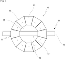
- FIGS. 3A and 3B are a plan view in which the outer case of the present disclosure is viewed from the above and a partial enlarged view illustrating a strength reinforcement part and a shock absorption part of the outer case, respectively.
- FIG. 4 is a bottom view in which the outer case 100 is viewed from below.
- the outer case 100 may have a polygonal pillar shape and the outer case 100 may have an outer bottom supporting part 102 formed in a lower portion thereof and a wire accommodation part 103 formed therein and configured to accommodate a wound welding wire (not shown).
- an inner case which will be described below may be located adjacent to an inner surface 104 and an accommodation space part 130 from which a strap 500 which will be described below is exposed may be formed in an outer surface 105.
- a strap guide 700 which will be described below may be coupled to the accommodation space part 130.
- the outer case 100 may include a strength reinforcement part 110 and a shock absorption part 120 formed at an inner side of the strength reinforcement part 110 to absorb an external impact.
- the strength reinforcement part 110 includes a first cardboard 112 and a first corrugated cardboard 111.
- a cross-sectional shape of the first corrugated cardboard 111 may roughly be a sine-functional wave shape. Due to the shape of the first corrugated cardboard 111, compression load strength and buckling load strength of the strength reinforcement part 110 may be improved.
- the first cardboard 112 may be formed of an outer first cardboard 112a and an inner first cardboard 112b.
- the shock absorption part 120 includes a second cardboard 122 and a second corrugated cardboard 121.
- a cross-sectional shape of the second corrugated cardboard 121 may roughly be a shape in which pentagons are repeatedly disposed. Due to the shape of the second corrugated cardboard 121, an impact force applied to the shock absorption part 120 is effectively absorbed.
- the second cardboard 122 may be formed of an outer second cardboard 122a and an inner second cardboard 122b. Meanwhile, according to the embodiment of the present disclosure, the inner first cardboard 112b and the outer second cardboard 122a may be integrally formed.
- the outer case 100 since the strength reinforcement part 110 is formed at the outside and the shock absorption part 120 is formed at the inside, when the shock is applied, the outer case 100 is not dented or damaged and the shock is not transferred to the welding wire accommodated in the outer case 100. Accordingly, since a separate storage unit 1000 for welding wire configured to accommodate the welding wire is stacked on the storage unit 1000 for welding wire, the outer case 100 of the lower storage unit 1000 for welding wire does not buckle even when a load is applied.
- the outer side of the strength reinforcement part 110 may be coated with a synthetic resin having watertightness. Accordingly, the inside of the strength reinforcement part 110 may be protected from external moisture or the like.
- the number of corrugations 111a per unit length of the first corrugated cardboard 111 may be formed to be greater than the number of corrugations 121a of the second corrugated cardboard 121. Accordingly, in the strength reinforcement part 110, a gap between the outer first cardboard 112a and the inner first cardboard 112b is not easily compressed relatively, and the strength reinforcement part 110 may efficiently resist against a compressing force. Meanwhile, in the shock absorption part 120, since a gap between the outer second cardboard 122a and the inner second cardboard 122b is easily compressed relatively, the shock absorption part 120 may efficiently absorb the shock.
- R1 has a value within the above described numerical range, resistance of the strength reinforcement part 110 against a compressing force is maximized without degradation of production efficiency.
- the length between the corrugation of the second corrugated cardboard 121 and the next corrugation adjacent to the corrugation of the second corrugated cardboard becomes excessively greater than the thickness of the shock absorption part 120. Accordingly, since the second corrugated cardboard 121 is easily deformed even by a light shock, a shock occurring in a working environment while the welding wire is carried may not be completely absorbed.
- R2 has a value within the above described numerical range, a shock absorption effect of the second corrugated cardboard 121 may be optimized.
- RC C1 / C2 may be in a range from 1.27 to 1.67 and may preferably be in a range from 1.37 to 1.57.
- the outer case 100 may be dented or damaged.
- the shock absorption part 120 has a resistance against an external impact, the external impact is transferred to the welding wire accommodated in the storage unit 1000 and thus the welding wire may be damaged.
- the thickness d2 of the shock absorption part 120 may be greater than the thickness d1 of the strength reinforcement part 110. Accordingly, the strength reinforcement part 110 may serve to provide strength to the outer case 100, and the shock absorption part 120 may easily absorb an external impact applied to the outer case 100.
- an outer bottom supporting part 102 may have a trapezoid shape in which a length of an inner side 102b is smaller than that of an outer side 102a and may preferably have an isosceles trapezoid shape. Further, the outer bottom supporting part 102 may be formed in a manner which is integrated with the outer surface 105, extended from the outer surface 105, and folded at a lower edge. In addition, the outer bottom supporting part 102 may also be formed to have a structure of the strength reinforcement part (110, see FIG. 3 ) and the shock absorption part (120, see FIG. 3 ).
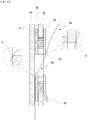
- FIG. 5A is a cutaway view of a state in which the outer case 100 according to the embodiment of the present disclosure, a bottom part 200, a bottom reinforcement part 210, an elasticity retaining plate 400, an elastic body retaining part 450, the strap guide 700, and the strap 500 are coupled
- FIGS. 5B and 5C are partial enlarged views of a part of FIG. 5A .
- the bottom part 200 may have a polygonal shape corresponding to a cross-sectional shape of the outer case 100 and may be seated on and coupled to the outer bottom supporting part 102.
- the bottom part 200 may also be formed to have the structure of the strength reinforcement part (110, see FIG. 3 ) and the shock absorption part (120, see FIG. 3 ). Further, the structure of the strength reinforcement part may be formed at an upper side and the structure of the shock absorption part may be formed at a lower side. Accordingly, since dents or damage does not easily occur even when an external force is applied in a vertical direction of the outer case 100 and the external force is easily absorbed, the welding wire accommodated in the storage unit 1000 may be stably protected.
- the bottom reinforcement part 210 may be disposed on the bottom part 200. Further, the bottom reinforcement part 210 may also be formed to have the structure of the strength reinforcement part (110, see FIG. 3 ) and the shock absorption part (120, see FIG. 3 ).
- the bottom reinforcement part 210 may be formed so that the structure of the shock absorption part is formed at an upper side and the structure of the strength reinforcement part is formed at a lower side. Accordingly, the bottom reinforcement part 210 may easily absorb a shock applied when the welding wire is accommodated.
- a hole (not shown) which is capable of coupling the elastic body retaining part 450 which will be described below may be formed in a center portion of each of the bottom part 200 and the bottom reinforcement part 210.
- the elasticity retaining plate 400 may be disposed on the bottom reinforcement part 210. Further, the elasticity retaining plate 400 may also be formed to have the structure of the strength reinforcement part (110, see FIG. 3 ) and the shock absorption part (120, see FIG. 3 ). Alternatively, the elasticity retaining plate 400 may be formed to have a structure in which multiple layers of scrap paper are stacked to have a compressed structure.
- a hole (not shown) may be formed in a center portion of the elasticity retaining plate 400, and the elastic body retaining part 450 may be coupled to the elasticity retaining plate 400 through the hole. More specifically, an upper coupling part 460 of the elastic body retaining part 450 passes through the holes (not shown) formed in the center portions of the elasticity retaining plate 400, the bottom reinforcement part 210, and the bottom part 200 from an upper side of the elasticity retaining plate 400 to be coupled therewith, and a lower coupling part 480 of the elastic body retaining part 450 configured to serve as an engaging port may be engaged with the upper coupling part 460 at a lower side of the bottom part 200.
- the upper coupling part 460 of the elastic body retaining part 450 includes a ring-shaped elastic body engaging portion 470 having an upper side with which an elastic body may be engaged.
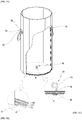
- FIG. 6 is a perspective view illustrating an inner case 300 according to the embodiment of the present disclosure
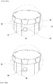
- FIG. 7 is a bottom view in which the inner case 300 of the present disclosure is viewed from below
- FIGS. 8A and 8B are a cutaway view of the inner case of the present disclosure and a partial enlarged view of a part of FIG. 8A , respectively.
- the inner case 300 may have a cylindrical pillar shape.
- An inner bottom supporting part 302 may be formed in a lower portion of the inner case 300 and a wire accommodation part 303 capable of accommodating wound welding wires (not shown) may be formed in the inner case 300.
- the inner case 300 may be detachably inserted into the outer case 100, and when the inner case 300 is inserted into the outer case 100, an outer surface 305 of the inner case 300 comes into close contact with the inner surface 104 of the outer case 100.
- the inner case 300 may be formed of paper. Specifically, since the inner case 300 may be made of a hard board formed by pressing multiple layers of cardboard, the cylindrical shape may be solidly maintained.
- the inner bottom supporting part 302 may be formed to have the structure of the strength reinforcement part (110, see FIG. 3 ) and the shock absorption part (120, see FIG. 3 ). Accordingly, the shock applied when the welding wire is accommodated may be easily absorbed.
- a hole 306 may be formed in a center portion of the inner bottom supporting part 302.
- the elastic body retaining part 450 may be exposed and coupled to a tensile spring through the hole 306.
- a residual amount check part 310 capable of checking a residual amount of the wound wires and a retainer guide 320 capable of guiding the movement of a retainer (not shown) may be formed in an inner surface 304 of the inner case 300.
- At least one cut portion 307 may be formed in an outer surface 305 of the inner case 300 so that the inner case 300 is easily bent.
- a shape of the cut portion 307 may be a cut groove having a predetermined depth, a dotted line shape, or another cut shape.
- the number of cut portions 307 is not limited, the cut portions 307 may preferably be three cut portions formed at 120° angles so that the inner case 300 may maintain solidity and may be easily bent when discarded.
- the inner case 300 made of a solid hard board may be easily processed, and the time for discarding may be reduced.
- FIGS. 9A and 9B are an exploded view illustrating a case in which the inner case is inserted into the outer case of the present disclosure and the cap covers the upper portion of the outer case on the basis of axis L and a view illustrating a state in which the outer case and the inner case of the present disclosure are coupled, respectively.
- the outer case 100 and the inner case 300 may be assembled.
- the strap 500 may be interposed between the outer surface 305 of the inner case 300 and the inner surface 104 of the outer case 100. Accordingly, the whole strap 500 except a portion exposed to the outer side of the outer case 100 is stably maintained by a friction force between the inner case 300 and the outer case 100.
- the storage unit 1000 for welding wire of the present disclosure may stably protect the welding wire accommodated therein even against an external impact applied in a lateral direction, and may not be bent or damaged even when a buckling load is applied from the above.
- a five-layer structure may be formed by the outer bottom supporting part 102, the bottom part 200, the bottom reinforcement part 210, the elasticity retaining plate 400, and the inner bottom supporting part 302. Accordingly, the storage unit 1000 may stably bear a weight of the welding wire accommodated therein, and the welding wire may be stably protected against a load and shock applied in a vertical direction to the storage unit 1000 for welding wire according to the embodiment of the present disclosure.
- FIGS. 10A and 10B are a front view of the accommodation space part of the storage unit for welding wire according to the embodiment of the present disclosure and a front view of the accommodation space part to which the strap guide is coupled, respectively
- FIGS. 11A and 11B are a perspective view of the accommodation space part of the storage unit for welding wire according to the embodiment of the present disclosure and a perspective view of the accommodation space part to which the strap guide is coupled, respectively
- FIGS. 12A and 12B are perspective views of a first module and a second module of the strap guide according to the embodiment, respectively.
- the storage unit 1000 for welding wire may include at least two accommodation space parts 130 configured to accommodate at least two strap guides 700.
- the strap guides 700 may be coupled to the storage unit 1000 for welding wire through the accommodation space parts 130, and the strap 500 may be exposed to the outer side of the outer case 100 through an opening 730 of the strap guide 700.
- the strap guide 700 is used in a manner in which a first module 710 and a second module 720 are coupled or separated through the accommodation space part 130 of the storage unit 1000 for welding wire.
- the first module 710 includes a first base 711, a strap boss 714, a first slot 715, and at least one protrusion accommodation part 712.
- the first base 711 may have a thin plate shape having a circular shape, a polygonal shape, or the like.
- the strap boss 714 may be formed to have a predetermined height at a center portion of the first base 711, and includes the first slot 715 surrounded by an inner circumferential surface of the strap boss 714.
- the protrusion accommodation part 712 may be formed in a height direction of the strap boss 714, and may be located at the outer side of the strap boss 714 to be spaced apart from the strap boss 714 at a predetermined interval.
- the protrusion accommodation part 712 may include a bore 713 configured to accommodate a coupling protrusion 722 of the second module 720, and may be variously formed according to a shape of the coupling protrusion.
- the protrusion accommodation part 712 may have a cylindrical shape to be easily coupled and separated.
- the number of protrusion accommodation parts 712 may be one or more. Further, two pairs of protrusion accommodation parts 712 may be formed above and below the strap boss 714 located at the center portion at predetermined intervals.
- the second module 720 includes a second base 721, a second slot 724, and at least one coupling protrusion 722.
- the second base 721 may have a thin plate shape having a circular shape, a polygonal shape, or the like.
- the second base 721 may have a shape corresponding to that of the first base 711.
- the second base 721 includes a bent portion 723 having an inclination angle and inclined toward the outside, and the second slot 724 located at a base center portion.
- the bent portion 723 may serve as a handle configured to allow the coupled strap guide 700 to be easily separated. Further, the bent portion 723 may be formed at one side of the second base 721 without limitation of a particular location in the second base 721. However, preferably, the bent portion 723 may be formed in a lower portion of the second base 721 so that the strap guide 700 may be easily separated from the storage unit 1000 for welding wire.
- the inclination angle of the bent portion 723 is appropriate when it is an angle which allows fingers to enter between the first module 710 and the second module 720 to separate the coupled strap guide 700 and allows a force to separate the strap guide 700 be smoothly transferred, and the inclination angle of the bent portion 723 may preferably be 10° to 20°.
- the coupling protrusion 722 may be located at an outer circumferential portion of the second slot 724 to be spaced apart from the second slot 724 at a predetermined interval, and forms a pair with the protrusion accommodation part 712 of the first module 710 when being coupled.
- the number of coupling protrusions 722 may be one or more and the number of coupling protrusions 722 may preferably be determined according to the number of protrusion accommodation parts 712.
- two pairs of coupling protrusions 722 may be formed above and below the second slot 724 located at the center portion at predetermined intervals.
- a shape of the coupling protrusion 722 may be formed in a shape corresponding to that of the bore 713 of the protrusion accommodation part 712.
- the coupling protrusion 722 may have a cylindrical shape which may be easily coupled and separated, and a corner portion of the cylinder may have a gentle round shape.
- FIG. 13 shows a cutaway view of the storage unit for welding wire to which the strap guide according to the embodiment of the present disclosure is coupled and a partial enlarged view of an edge of the opening.
- an edge of the accommodation space part 130 of the storage unit 1000 for welding wire may become weak to external actions, and when the opening 730 having the single closed surface is formed, since various external actions may be blocked, durability of the storage unit 1000 for welding wire may be improved. Further, the strap 500 may pass through the opening 730 and may be supported by an edge 731 of the opening 730.
- the edge 731 of the opening 730 which comes into contact with the strap 500 may have a gentle round shape to improve a supporting force of the strap 500.
- the strap 500 since an area in which the strap 500 and the edge 731 of the opening 730 come into contact with each other increases, the strap 500 may be more solidly and safely supported.
- the accommodation space part 130 may include a center space part 131 into which the strap boss 714 is fitted, and an upper space part 132 and a lower space part 133 into which the protrusion accommodation parts 712 are fitted, and the strap guide 700 may be fitted into the accommodation space part 130.
- the center space part 131 may be formed according to the shape of strap boss 714 and the upper space part 132 and the lower space part 133 may be formed according to shapes of the protrusion accommodation part 712.
- the strap guide 700 and the storage unit 1000 for welding wire are engaged without shaking and do not rotate in a coupled state, and thus are stable.
- a shape in which the protrusion accommodation parts 712 are fitted into the upper space part 132 and the lower space part 133 may be changed according to the number of protrusion accommodation parts 712.
- a height of the strap boss 714 may be greater than or equal to a thickness of the outer case 100 to protect the storage unit 1000 for welding wire made of paper.
- the thickness of the outer case 100 does not exceed the height of the strap boss 714 but is less than or equal to the height of the strap boss 714 in a state in which the first module 710 and the second module 720 are securely coupled and thus the outer case 100 may be protected from an external influence, the durability of the storage unit 1000 for welding wire may be improved.
- the storage unit 1000 for welding wire may be formed in a double-layer structure of the outer case 100 and the inner case 300, and in this case, the storage unit 1000 for welding wire may be a storage unit 1000 for welding wire in which the first module 710 is disposed in an interspace part 800 between the outer case 100 and the inner case 300 of the storage unit 1000 for welding wire and the second module 720 passes through the accommodation space part 130 formed in a side portion of the outer case 100 of the storage unit 1000 for welding wire to be coupled to the first module 710.
- the storage unit 1000 for welding wire further includes a strap 500.
- the strap 500 may be formed of a synthetic resin such as nylon, polyester, or the like.
- a center portion 501 of the strap 500 may be disposed between the outer bottom supporting part 102 and the bottom part 200. Further, both end portions 502 of the strap 500 may be exposed to the accommodation space part 130 formed to face the outer surface 105 of the outer case 100 or the opening 730 of the strap guide 700 coupled to the accommodation space part 130 to form engaging portions 510.
- the center portion 501 of the strap 500 is pressed by the welding wire. Further, arms (not shown) of a lifting device are inserted into both engaging portions 510 and the storage unit 1000 for welding wire is carried in a state of being spaced apart from the ground. In this case, the strap 500 may stably support the welding wire.
- the strap 500 may be disposed without being adhered to the outer case 100 so that the engaging portion 510 at the other side may move when the engaging portion 510 at one side is pulled. Accordingly, the strap 500 is conveniently assembled and is easily separated when the storage unit 1000 for welding wire of the present disclosure is discarded.
- the bottom part 200 and the like are disposed on the strap 500 and the welding wire is accommodated on the bottom part 200 and the like to be carried even when the strap 500 and the outer case 100 are coupled without being adhered to each other, the strap 500 does not easily move due to the weight of the welding wire. Accordingly, the welding wire becomes stable to be accommodated and carried.
- an outer case includes a strength reinforcement part and a shock absorption part and an inner case is closely coupled to the inside of the outer case, a storage unit for welding wire is not dented or damaged and an inner welding wire can be stably protected even when an external impact is applied.
- buckling does not occur even when the storage units for welding wire according to the present disclosure are vertically stacked.
- the storage unit for welding wire can be made of a paper material, an addition made of other materials such as metal, plastic, or the like to reinforce the storage unit is not necessary, and a strap is easily disassembled, disassembling and recycling the storage unit for welding wire is easy.
- transportation costs required to recycle the used storage unit for welding wire and costs necessary to process the storage unit for welding wire as industrial waste can be reduced.
- the outer side of the strength reinforcement part can be coated with a synthetic resin having watertightness, the inside can be protected from external moisture or the like.
- the storage unit for welding wire can stably bear a weight of the welding wire accommodated therein, and can stably protect the welding wire from a load and shock in a vertical direction.
- the storage unit for welding wire having an accommodation space part into which a strap guide can be fitted is stable because the strap guide does not rotate and can be engaged without shaking when the storage unit is lifted or moves.
- first module and a second module are coupled to the accommodation space part of the storage unit for welding wire to form an opening of the strap guide having a single closed surface, the storage unit for welding wire can be safely protected from external actions.
- the strap can be solidly and safely supported.
- the strap guide coupled to the storage unit for welding wire can be easily separated by hand.
- the inner case includes at least one cut portion in an outer surface thereof, the inner case made of a solid hard board can be easily discarded and the time for discarding can be reduced.
Landscapes
- Engineering & Computer Science (AREA)
- Mechanical Engineering (AREA)
- Packaging Of Annular Or Rod-Shaped Articles, Wearing Apparel, Cassettes, Or The Like (AREA)
Applications Claiming Priority (1)
| Application Number | Priority Date | Filing Date | Title |
|---|---|---|---|
| KR1020180024311A KR101997737B1 (ko) | 2018-02-28 | 2018-02-28 | 용접 와이어용 수납 용기 |
Publications (2)
| Publication Number | Publication Date |
|---|---|
| EP3536635A1 true EP3536635A1 (de) | 2019-09-11 |
| EP3536635B1 EP3536635B1 (de) | 2020-12-16 |
Family
ID=65894844
Family Applications (1)
| Application Number | Title | Priority Date | Filing Date |
|---|---|---|---|
| EP19159282.3A Active EP3536635B1 (de) | 2018-02-28 | 2019-02-26 | Aufbewahrungseinheit für schweissdraht |
Country Status (4)
| Country | Link |
|---|---|
| US (1) | US10899495B2 (de) |
| EP (1) | EP3536635B1 (de) |
| JP (1) | JP6752315B2 (de) |
| KR (1) | KR101997737B1 (de) |
Families Citing this family (6)
| Publication number | Priority date | Publication date | Assignee | Title |
|---|---|---|---|---|
| KR102351609B1 (ko) * | 2020-06-26 | 2022-01-18 | 고려용접봉 주식회사 | 용접 와이어 수납용기용 덮개 |
| KR102398582B1 (ko) | 2020-08-18 | 2022-05-17 | 고려용접봉 주식회사 | 용접 와이어용 수납 용기 |
| USD940585S1 (en) * | 2020-09-03 | 2022-01-11 | LovePop, Inc. | Popup bouquet vase |
| US11793255B2 (en) | 2020-09-03 | 2023-10-24 | LovePop, Inc. | Imitation flower bouquet system |
| USD1033690S1 (en) * | 2021-04-15 | 2024-07-02 | Celine | Candle |
| US12227342B2 (en) * | 2021-10-04 | 2025-02-18 | Esab Ab | Sidewall support insert |
Citations (4)
| Publication number | Priority date | Publication date | Assignee | Title |
|---|---|---|---|---|
| JP2001301886A (ja) | 2000-04-20 | 2001-10-31 | Hiroshi Kondo | 段ボール紙容器を含む溶接ワイヤの組立式収納容器 |
| US20030019776A1 (en) * | 2001-07-11 | 2003-01-30 | Kabushiki Kaisha Kobe Seiko Sho(Kobe Steel, Ltd.) | Welding wire container |
| JP2003072872A (ja) * | 2001-08-31 | 2003-03-12 | Kobe Steel Ltd | 線材収容箱 |
| US20140215765A1 (en) * | 2012-02-13 | 2014-08-07 | Lincoln Global, Inc. | Strap guide insert |
Family Cites Families (48)
| Publication number | Priority date | Publication date | Assignee | Title |
|---|---|---|---|---|
| US1184749A (en) * | 1913-10-11 | 1916-05-30 | Oliver H Hicks | Corrugated board. |
| US2191291A (en) * | 1936-09-26 | 1940-02-20 | Inland Container Corp | Rim reinforced case and method of forming same |
| US2206314A (en) * | 1939-02-20 | 1940-07-02 | Willy W Werner | Box |
| US2794588A (en) * | 1954-12-06 | 1957-06-04 | Crown Zellerbach Corp | Closures for paperboard containers |
| US3012660A (en) * | 1959-06-08 | 1961-12-12 | Owens Illinois Glass Co | Shipping container for particulate solids |
| US3096224A (en) * | 1961-11-03 | 1963-07-02 | Tri Wall Containers Inc | Corrugated paper board product |
| US3293107A (en) * | 1963-01-30 | 1966-12-20 | Container Corp | Corrugated paperboard |
| US3932010A (en) * | 1975-01-23 | 1976-01-13 | All-Steel, Inc. | Flush pull arrangement for office furniture |
| US4358498A (en) * | 1980-09-24 | 1982-11-09 | Chavannes Marc A | Reinforced laminated and corrugated board-like structures and method for the manufacturing thereof |
| CN1006291B (zh) * | 1985-03-22 | 1990-01-03 | 维西(英国)有限公司 | 松散流动材料容器 |
| US4729505A (en) * | 1986-11-13 | 1988-03-08 | Weyerhaeuser Company | Heavy-duty shipping container for flowable bulk materials |
| US4693413A (en) * | 1986-11-20 | 1987-09-15 | International Paper Company | Laminated bulk bin corner structure |
| US4850506A (en) * | 1986-12-17 | 1989-07-25 | Connelly Containers, Inc. | Container for fluent material |
| US5057176A (en) * | 1988-05-10 | 1991-10-15 | Manville Corporation | Method of forming corrugated paperboard automotive liner |
| US5037027A (en) * | 1990-12-18 | 1991-08-06 | Bradford Company | Tote box construction |
| US5193701A (en) * | 1992-08-13 | 1993-03-16 | Pelikan, Inc. | Box for storing hanging file folders |
| US5295632B1 (en) * | 1992-12-18 | 1998-04-21 | Bradford Co | Tote box with self locking top rail |
| US5285957A (en) * | 1993-01-26 | 1994-02-15 | The Mead Corporation | Repulpable, reinforced corrugated containers |
| US5568774A (en) * | 1994-01-07 | 1996-10-29 | Miriam M. Benson | Pallets of corrugated sheet material with interlocking components |
| US5433156A (en) * | 1994-01-07 | 1995-07-18 | Miriam M. Benson | Construction of pallets from corrugated sheet material |
| US5520477A (en) * | 1994-06-07 | 1996-05-28 | Seagate, Plastics | Connecting system |
| US5522539A (en) * | 1994-12-16 | 1996-06-04 | Bradford Company | Tote box with block insert locking capability |
| JP3013182U (ja) * | 1994-12-28 | 1995-07-11 | 住金溶接工業株式会社 | 主として粉体、液体等を収容する紙製包装容器 |
| US5462221A (en) * | 1995-01-04 | 1995-10-31 | Bradford Company | Tote box handle |
| KR0183515B1 (ko) * | 1995-04-11 | 1999-04-15 | 김승무 | 2중 골심판지 및 그 성형방법과 장치 |
| US5921391A (en) * | 1997-11-26 | 1999-07-13 | Stone Container Corporation | Container for storing and transporting wire, cord and the like |
| US6343696B1 (en) * | 1999-04-06 | 2002-02-05 | Mccormick Richard Lee | Protective container |
| US6808105B2 (en) * | 2000-12-30 | 2004-10-26 | Dong-Jin Paper Board Box Co., Ltd. | Box for transportation |
| USD469012S1 (en) * | 2001-05-04 | 2003-01-21 | Dong-Jin Paper Board Box Co., Ltd. | Handle of a box |
| US6619540B1 (en) * | 2002-04-22 | 2003-09-16 | Bradford Company | Snap lock tote box handle and tote box construction |
| US20040007612A1 (en) * | 2002-07-11 | 2004-01-15 | Johanson James E. | Box hand hole reinforcement and method of use |
| JP2005029219A (ja) * | 2003-07-07 | 2005-02-03 | Yamato Shiki Co Ltd | 段ボール箱 |
| US7604156B2 (en) * | 2004-03-19 | 2009-10-20 | Georgia-Pacific Corrugated Llc | Reinforced fiberboard bulk container |
| JP3675809B1 (ja) * | 2004-08-31 | 2005-07-27 | 渡邊 隆久 | コンテナ用結合具およびこれを用いた組立式コンテナ |
| US7331506B2 (en) * | 2006-05-31 | 2008-02-19 | Hannspree, Inc. | Carton handle |
| WO2008008095A1 (en) * | 2006-07-13 | 2008-01-17 | Sundance Corrugated Products Company, Llc | Shipping pallet apparatus and methods |
| US8091768B2 (en) * | 2009-05-26 | 2012-01-10 | International Paper Company | Bulk shipping container |
| KR101195000B1 (ko) * | 2009-06-01 | 2012-10-25 | 허은성 | 포장팩용 손잡이 |
| US8597455B1 (en) * | 2009-10-02 | 2013-12-03 | Metacomb, Inc. | Translucent building material comprising corrugated cardboard |
| CN201512727U (zh) * | 2009-10-19 | 2010-06-23 | 李新桥 | 一种单瓦三层高弹性耐冲击瓦楞纸板 |
| US8652613B2 (en) * | 2010-02-09 | 2014-02-18 | Master-Pack Sdn. Bhn. | Quadruple-wall corrugated paperboard and method of manufacture |
| US8365912B2 (en) * | 2010-10-21 | 2013-02-05 | Lincoln Global, Inc. | Wire containment structure including container and bag |
| HUE032995T2 (en) * | 2012-07-05 | 2017-11-28 | Progroup Ag | Method and apparatus for the manufacture of corrugated board products having an oblique wave profile |
| KR20140099175A (ko) * | 2013-02-01 | 2014-08-11 | 이정혁 | 미세골을 갖는 2층 구조의 골판지 및 이를 이용한 포장재 |
| US8978964B1 (en) * | 2013-03-15 | 2015-03-17 | Thomas S. Ruggiere, Sr. | Reinforced corrugated container with an exterior sleeve |
| CN103334348A (zh) * | 2013-06-14 | 2013-10-02 | 昆山三达包装有限公司 | 一种新型瓦楞纸板 |
| CN204914778U (zh) * | 2015-08-28 | 2015-12-30 | 东莞华成纸业有限公司 | 一种耐压抗弯瓦楞纸板 |
| CN205522727U (zh) * | 2016-04-12 | 2016-08-31 | 宝艺新材料股份有限公司 | 一种环保型防火瓦楞纸板 |
-
2018
- 2018-02-28 KR KR1020180024311A patent/KR101997737B1/ko active Active
-
2019
- 2019-02-26 EP EP19159282.3A patent/EP3536635B1/de active Active
- 2019-02-27 JP JP2019034874A patent/JP6752315B2/ja active Active
- 2019-02-28 US US16/288,645 patent/US10899495B2/en active Active
Patent Citations (4)
| Publication number | Priority date | Publication date | Assignee | Title |
|---|---|---|---|---|
| JP2001301886A (ja) | 2000-04-20 | 2001-10-31 | Hiroshi Kondo | 段ボール紙容器を含む溶接ワイヤの組立式収納容器 |
| US20030019776A1 (en) * | 2001-07-11 | 2003-01-30 | Kabushiki Kaisha Kobe Seiko Sho(Kobe Steel, Ltd.) | Welding wire container |
| JP2003072872A (ja) * | 2001-08-31 | 2003-03-12 | Kobe Steel Ltd | 線材収容箱 |
| US20140215765A1 (en) * | 2012-02-13 | 2014-08-07 | Lincoln Global, Inc. | Strap guide insert |
Also Published As
| Publication number | Publication date |
|---|---|
| JP2019150876A (ja) | 2019-09-12 |
| KR101997737B1 (ko) | 2019-07-08 |
| JP6752315B2 (ja) | 2020-09-09 |
| EP3536635B1 (de) | 2020-12-16 |
| US20190263555A1 (en) | 2019-08-29 |
| US10899495B2 (en) | 2021-01-26 |
Similar Documents
| Publication | Publication Date | Title |
|---|---|---|
| EP3536635B1 (de) | Aufbewahrungseinheit für schweissdraht | |
| US20080142626A1 (en) | Pail-Pack for Welding Wire | |
| EP1673994A1 (de) | Herstellungsverfahren für eine Öse und zugehörige Struktur | |
| EP1932612A1 (de) | Eimerpaket für einen Schweißdraht | |
| EP3023345B1 (de) | Verpackungsschachtel aus wellpappe | |
| JP7487988B2 (ja) | 溶接ワイヤー用収納容器 | |
| KR102521090B1 (ko) | 손잡이 일체형 박스 | |
| KR101883303B1 (ko) | 용접 와이어용 수납 용기 | |
| US10858173B2 (en) | Strap guide and pail pack having the same | |
| WO2022085422A1 (ja) | 電池パック | |
| KR200404101Y1 (ko) | 포장용 완충재 | |
| KR200490926Y1 (ko) | 용접봉 포장통 | |
| KR101977144B1 (ko) | 일체형 내부 받침판을 구비한 포장박스 | |
| JP2009051515A (ja) | 耐衝撃性容器 | |
| CN222224818U (zh) | 提手组件以及包装盒 | |
| KR101384282B1 (ko) | 휴대 단말 수납 케이스 | |
| KR200464052Y1 (ko) | 패널제품용 포장박스 | |
| KR20090132480A (ko) | 슬라이딩 타입의 핸드폰에 장착되는 슬라이딩 모듈용 탄성장치 | |
| KR20230138341A (ko) | 4 도어 냉장고용 박스포장 케이스 | |
| JP2012144271A (ja) | 緩衝梱包材 | |
| JP3214042U (ja) | コンデンサ用タブ端子の収納容器 | |
| KR200434464Y1 (ko) | 용접 와이어 수납용 페일팩 | |
| JP2024027053A (ja) | 蒸着マスク用ケース | |
| JP2007204086A (ja) | カートリッジ収納ケース | |
| JPH0547114Y2 (de) |
Legal Events
| Date | Code | Title | Description |
|---|---|---|---|
| PUAI | Public reference made under article 153(3) epc to a published international application that has entered the european phase |
Free format text: ORIGINAL CODE: 0009012 |
|
| STAA | Information on the status of an ep patent application or granted ep patent |
Free format text: STATUS: REQUEST FOR EXAMINATION WAS MADE |
|
| 17P | Request for examination filed |
Effective date: 20190325 |
|
| AK | Designated contracting states |
Kind code of ref document: A1 Designated state(s): AL AT BE BG CH CY CZ DE DK EE ES FI FR GB GR HR HU IE IS IT LI LT LU LV MC MK MT NL NO PL PT RO RS SE SI SK SM TR |
|
| AX | Request for extension of the european patent |
Extension state: BA ME |
|
| RBV | Designated contracting states (corrected) |
Designated state(s): AL AT BE BG CH CY CZ DE DK EE ES FI FR GB GR HR HU IE IS IT LI LT LU LV MC MK MT NL NO PL PT RO RS SE SI SK SM TR |
|
| GRAP | Despatch of communication of intention to grant a patent |
Free format text: ORIGINAL CODE: EPIDOSNIGR1 |
|
| STAA | Information on the status of an ep patent application or granted ep patent |
Free format text: STATUS: GRANT OF PATENT IS INTENDED |
|
| INTG | Intention to grant announced |
Effective date: 20200709 |
|
| GRAS | Grant fee paid |
Free format text: ORIGINAL CODE: EPIDOSNIGR3 |
|
| GRAA | (expected) grant |
Free format text: ORIGINAL CODE: 0009210 |
|
| STAA | Information on the status of an ep patent application or granted ep patent |
Free format text: STATUS: THE PATENT HAS BEEN GRANTED |
|
| AK | Designated contracting states |
Kind code of ref document: B1 Designated state(s): AL AT BE BG CH CY CZ DE DK EE ES FI FR GB GR HR HU IE IS IT LI LT LU LV MC MK MT NL NO PL PT RO RS SE SI SK SM TR |
|
| REG | Reference to a national code |
Ref country code: GB Ref legal event code: FG4D |
|
| REG | Reference to a national code |
Ref country code: DE Ref legal event code: R096 Ref document number: 602019001708 Country of ref document: DE |
|
| REG | Reference to a national code |
Ref country code: IE Ref legal event code: FG4D |
|
| REG | Reference to a national code |
Ref country code: AT Ref legal event code: REF Ref document number: 1345389 Country of ref document: AT Kind code of ref document: T Effective date: 20210115 |
|
| REG | Reference to a national code |
Ref country code: DE Ref legal event code: R082 Ref document number: 602019001708 Country of ref document: DE Representative=s name: V. FUENER EBBINGHAUS FINCK HANO, DE |
|
| PG25 | Lapsed in a contracting state [announced via postgrant information from national office to epo] |
Ref country code: FI Free format text: LAPSE BECAUSE OF FAILURE TO SUBMIT A TRANSLATION OF THE DESCRIPTION OR TO PAY THE FEE WITHIN THE PRESCRIBED TIME-LIMIT Effective date: 20201216 Ref country code: RS Free format text: LAPSE BECAUSE OF FAILURE TO SUBMIT A TRANSLATION OF THE DESCRIPTION OR TO PAY THE FEE WITHIN THE PRESCRIBED TIME-LIMIT Effective date: 20201216 Ref country code: GR Free format text: LAPSE BECAUSE OF FAILURE TO SUBMIT A TRANSLATION OF THE DESCRIPTION OR TO PAY THE FEE WITHIN THE PRESCRIBED TIME-LIMIT Effective date: 20210317 Ref country code: NO Free format text: LAPSE BECAUSE OF FAILURE TO SUBMIT A TRANSLATION OF THE DESCRIPTION OR TO PAY THE FEE WITHIN THE PRESCRIBED TIME-LIMIT Effective date: 20210316 |
|
| REG | Reference to a national code |
Ref country code: AT Ref legal event code: MK05 Ref document number: 1345389 Country of ref document: AT Kind code of ref document: T Effective date: 20201216 |
|
| REG | Reference to a national code |
Ref country code: NL Ref legal event code: MP Effective date: 20201216 |
|
| PG25 | Lapsed in a contracting state [announced via postgrant information from national office to epo] |
Ref country code: LV Free format text: LAPSE BECAUSE OF FAILURE TO SUBMIT A TRANSLATION OF THE DESCRIPTION OR TO PAY THE FEE WITHIN THE PRESCRIBED TIME-LIMIT Effective date: 20201216 Ref country code: SE Free format text: LAPSE BECAUSE OF FAILURE TO SUBMIT A TRANSLATION OF THE DESCRIPTION OR TO PAY THE FEE WITHIN THE PRESCRIBED TIME-LIMIT Effective date: 20201216 Ref country code: BG Free format text: LAPSE BECAUSE OF FAILURE TO SUBMIT A TRANSLATION OF THE DESCRIPTION OR TO PAY THE FEE WITHIN THE PRESCRIBED TIME-LIMIT Effective date: 20210316 |
|
| PG25 | Lapsed in a contracting state [announced via postgrant information from national office to epo] |
Ref country code: NL Free format text: LAPSE BECAUSE OF FAILURE TO SUBMIT A TRANSLATION OF THE DESCRIPTION OR TO PAY THE FEE WITHIN THE PRESCRIBED TIME-LIMIT Effective date: 20201216 Ref country code: HR Free format text: LAPSE BECAUSE OF FAILURE TO SUBMIT A TRANSLATION OF THE DESCRIPTION OR TO PAY THE FEE WITHIN THE PRESCRIBED TIME-LIMIT Effective date: 20201216 |
|
| REG | Reference to a national code |
Ref country code: LT Ref legal event code: MG9D |
|
| PG25 | Lapsed in a contracting state [announced via postgrant information from national office to epo] |
Ref country code: LT Free format text: LAPSE BECAUSE OF FAILURE TO SUBMIT A TRANSLATION OF THE DESCRIPTION OR TO PAY THE FEE WITHIN THE PRESCRIBED TIME-LIMIT Effective date: 20201216 Ref country code: PT Free format text: LAPSE BECAUSE OF FAILURE TO SUBMIT A TRANSLATION OF THE DESCRIPTION OR TO PAY THE FEE WITHIN THE PRESCRIBED TIME-LIMIT Effective date: 20210416 Ref country code: RO Free format text: LAPSE BECAUSE OF FAILURE TO SUBMIT A TRANSLATION OF THE DESCRIPTION OR TO PAY THE FEE WITHIN THE PRESCRIBED TIME-LIMIT Effective date: 20201216 Ref country code: SM Free format text: LAPSE BECAUSE OF FAILURE TO SUBMIT A TRANSLATION OF THE DESCRIPTION OR TO PAY THE FEE WITHIN THE PRESCRIBED TIME-LIMIT Effective date: 20201216 Ref country code: SK Free format text: LAPSE BECAUSE OF FAILURE TO SUBMIT A TRANSLATION OF THE DESCRIPTION OR TO PAY THE FEE WITHIN THE PRESCRIBED TIME-LIMIT Effective date: 20201216 Ref country code: EE Free format text: LAPSE BECAUSE OF FAILURE TO SUBMIT A TRANSLATION OF THE DESCRIPTION OR TO PAY THE FEE WITHIN THE PRESCRIBED TIME-LIMIT Effective date: 20201216 Ref country code: CZ Free format text: LAPSE BECAUSE OF FAILURE TO SUBMIT A TRANSLATION OF THE DESCRIPTION OR TO PAY THE FEE WITHIN THE PRESCRIBED TIME-LIMIT Effective date: 20201216 |
|
| PG25 | Lapsed in a contracting state [announced via postgrant information from national office to epo] |
Ref country code: PL Free format text: LAPSE BECAUSE OF FAILURE TO SUBMIT A TRANSLATION OF THE DESCRIPTION OR TO PAY THE FEE WITHIN THE PRESCRIBED TIME-LIMIT Effective date: 20201216 Ref country code: AT Free format text: LAPSE BECAUSE OF FAILURE TO SUBMIT A TRANSLATION OF THE DESCRIPTION OR TO PAY THE FEE WITHIN THE PRESCRIBED TIME-LIMIT Effective date: 20201216 |
|
| REG | Reference to a national code |
Ref country code: DE Ref legal event code: R097 Ref document number: 602019001708 Country of ref document: DE |
|
| PG25 | Lapsed in a contracting state [announced via postgrant information from national office to epo] |
Ref country code: MC Free format text: LAPSE BECAUSE OF FAILURE TO SUBMIT A TRANSLATION OF THE DESCRIPTION OR TO PAY THE FEE WITHIN THE PRESCRIBED TIME-LIMIT Effective date: 20201216 Ref country code: IS Free format text: LAPSE BECAUSE OF FAILURE TO SUBMIT A TRANSLATION OF THE DESCRIPTION OR TO PAY THE FEE WITHIN THE PRESCRIBED TIME-LIMIT Effective date: 20210416 |
|
| PLBE | No opposition filed within time limit |
Free format text: ORIGINAL CODE: 0009261 |
|
| STAA | Information on the status of an ep patent application or granted ep patent |
Free format text: STATUS: NO OPPOSITION FILED WITHIN TIME LIMIT |
|
| REG | Reference to a national code |
Ref country code: BE Ref legal event code: MM Effective date: 20210228 |
|
| PG25 | Lapsed in a contracting state [announced via postgrant information from national office to epo] |
Ref country code: IT Free format text: LAPSE BECAUSE OF FAILURE TO SUBMIT A TRANSLATION OF THE DESCRIPTION OR TO PAY THE FEE WITHIN THE PRESCRIBED TIME-LIMIT Effective date: 20201216 Ref country code: LU Free format text: LAPSE BECAUSE OF NON-PAYMENT OF DUE FEES Effective date: 20210226 Ref country code: AL Free format text: LAPSE BECAUSE OF FAILURE TO SUBMIT A TRANSLATION OF THE DESCRIPTION OR TO PAY THE FEE WITHIN THE PRESCRIBED TIME-LIMIT Effective date: 20201216 |
|
| 26N | No opposition filed |
Effective date: 20210917 |
|
| PG25 | Lapsed in a contracting state [announced via postgrant information from national office to epo] |
Ref country code: DK Free format text: LAPSE BECAUSE OF FAILURE TO SUBMIT A TRANSLATION OF THE DESCRIPTION OR TO PAY THE FEE WITHIN THE PRESCRIBED TIME-LIMIT Effective date: 20201216 |
|
| PG25 | Lapsed in a contracting state [announced via postgrant information from national office to epo] |
Ref country code: ES Free format text: LAPSE BECAUSE OF FAILURE TO SUBMIT A TRANSLATION OF THE DESCRIPTION OR TO PAY THE FEE WITHIN THE PRESCRIBED TIME-LIMIT Effective date: 20201216 Ref country code: FR Free format text: LAPSE BECAUSE OF NON-PAYMENT OF DUE FEES Effective date: 20210228 Ref country code: IE Free format text: LAPSE BECAUSE OF NON-PAYMENT OF DUE FEES Effective date: 20210226 |
|
| PG25 | Lapsed in a contracting state [announced via postgrant information from national office to epo] |
Ref country code: SI Free format text: LAPSE BECAUSE OF FAILURE TO SUBMIT A TRANSLATION OF THE DESCRIPTION OR TO PAY THE FEE WITHIN THE PRESCRIBED TIME-LIMIT Effective date: 20201216 |
|
| PG25 | Lapsed in a contracting state [announced via postgrant information from national office to epo] |
Ref country code: IS Free format text: LAPSE BECAUSE OF FAILURE TO SUBMIT A TRANSLATION OF THE DESCRIPTION OR TO PAY THE FEE WITHIN THE PRESCRIBED TIME-LIMIT Effective date: 20210416 |
|
| PG25 | Lapsed in a contracting state [announced via postgrant information from national office to epo] |
Ref country code: BE Free format text: LAPSE BECAUSE OF NON-PAYMENT OF DUE FEES Effective date: 20210228 |
|
| REG | Reference to a national code |
Ref country code: CH Ref legal event code: PL |
|
| PG25 | Lapsed in a contracting state [announced via postgrant information from national office to epo] |
Ref country code: LI Free format text: LAPSE BECAUSE OF NON-PAYMENT OF DUE FEES Effective date: 20220228 Ref country code: CH Free format text: LAPSE BECAUSE OF NON-PAYMENT OF DUE FEES Effective date: 20220228 |
|
| REG | Reference to a national code |
Ref country code: DE Ref legal event code: R081 Ref document number: 602019001708 Country of ref document: DE Owner name: KISWEL LTD., KR Free format text: FORMER OWNER: KISWEL HOLDINGS LTD., BUSAN, KR Ref country code: DE Ref legal event code: R081 Ref document number: 602019001708 Country of ref document: DE Owner name: KISWEL LTD., KR Free format text: FORMER OWNER: KISWEL LTD., BUSAN, KR |
|
| PG25 | Lapsed in a contracting state [announced via postgrant information from national office to epo] |
Ref country code: CY Free format text: LAPSE BECAUSE OF FAILURE TO SUBMIT A TRANSLATION OF THE DESCRIPTION OR TO PAY THE FEE WITHIN THE PRESCRIBED TIME-LIMIT Effective date: 20201216 |
|
| PG25 | Lapsed in a contracting state [announced via postgrant information from national office to epo] |
Ref country code: HU Free format text: LAPSE BECAUSE OF FAILURE TO SUBMIT A TRANSLATION OF THE DESCRIPTION OR TO PAY THE FEE WITHIN THE PRESCRIBED TIME-LIMIT; INVALID AB INITIO Effective date: 20190226 |
|
| PG25 | Lapsed in a contracting state [announced via postgrant information from national office to epo] |
Ref country code: MK Free format text: LAPSE BECAUSE OF FAILURE TO SUBMIT A TRANSLATION OF THE DESCRIPTION OR TO PAY THE FEE WITHIN THE PRESCRIBED TIME-LIMIT Effective date: 20201216 |
|
| PG25 | Lapsed in a contracting state [announced via postgrant information from national office to epo] |
Ref country code: MT Free format text: LAPSE BECAUSE OF FAILURE TO SUBMIT A TRANSLATION OF THE DESCRIPTION OR TO PAY THE FEE WITHIN THE PRESCRIBED TIME-LIMIT Effective date: 20201216 |
|
| PG25 | Lapsed in a contracting state [announced via postgrant information from national office to epo] |
Ref country code: TR Free format text: LAPSE BECAUSE OF FAILURE TO SUBMIT A TRANSLATION OF THE DESCRIPTION OR TO PAY THE FEE WITHIN THE PRESCRIBED TIME-LIMIT Effective date: 20201216 |
|
| PGFP | Annual fee paid to national office [announced via postgrant information from national office to epo] |
Ref country code: GB Payment date: 20260108 Year of fee payment: 8 |
|
| PGFP | Annual fee paid to national office [announced via postgrant information from national office to epo] |
Ref country code: DE Payment date: 20260105 Year of fee payment: 8 |