EP3536498B1 - Machine à laminer multifonction et procédé de laminage - Google Patents
Machine à laminer multifonction et procédé de laminage Download PDFInfo
- Publication number
- EP3536498B1 EP3536498B1 EP18803519.0A EP18803519A EP3536498B1 EP 3536498 B1 EP3536498 B1 EP 3536498B1 EP 18803519 A EP18803519 A EP 18803519A EP 3536498 B1 EP3536498 B1 EP 3536498B1
- Authority
- EP
- European Patent Office
- Prior art keywords
- laminating
- roller
- cylinder
- swing arm
- pressing
- Prior art date
- Legal status (The legal status is an assumption and is not a legal conclusion. Google has not performed a legal analysis and makes no representation as to the accuracy of the status listed.)
- Active
Links
Images


Classifications
-
- B—PERFORMING OPERATIONS; TRANSPORTING
- B32—LAYERED PRODUCTS
- B32B—LAYERED PRODUCTS, i.e. PRODUCTS BUILT-UP OF STRATA OF FLAT OR NON-FLAT, e.g. CELLULAR OR HONEYCOMB, FORM
- B32B37/00—Methods or apparatus for laminating, e.g. by curing or by ultrasonic bonding
- B32B37/14—Methods or apparatus for laminating, e.g. by curing or by ultrasonic bonding characterised by the properties of the layers
- B32B37/16—Methods or apparatus for laminating, e.g. by curing or by ultrasonic bonding characterised by the properties of the layers with all layers existing as coherent layers before laminating
- B32B37/20—Methods or apparatus for laminating, e.g. by curing or by ultrasonic bonding characterised by the properties of the layers with all layers existing as coherent layers before laminating involving the assembly of continuous webs only
- B32B37/203—One or more of the layers being plastic
-
- B—PERFORMING OPERATIONS; TRANSPORTING
- B32—LAYERED PRODUCTS
- B32B—LAYERED PRODUCTS, i.e. PRODUCTS BUILT-UP OF STRATA OF FLAT OR NON-FLAT, e.g. CELLULAR OR HONEYCOMB, FORM
- B32B37/00—Methods or apparatus for laminating, e.g. by curing or by ultrasonic bonding
- B32B37/0046—Methods or apparatus for laminating, e.g. by curing or by ultrasonic bonding characterised by constructional aspects of the apparatus
- B32B37/0053—Constructional details of laminating machines comprising rollers; Constructional features of the rollers
-
- B—PERFORMING OPERATIONS; TRANSPORTING
- B32—LAYERED PRODUCTS
- B32B—LAYERED PRODUCTS, i.e. PRODUCTS BUILT-UP OF STRATA OF FLAT OR NON-FLAT, e.g. CELLULAR OR HONEYCOMB, FORM
- B32B37/00—Methods or apparatus for laminating, e.g. by curing or by ultrasonic bonding
- B32B37/10—Methods or apparatus for laminating, e.g. by curing or by ultrasonic bonding characterised by the pressing technique, e.g. using action of vacuum or fluid pressure
-
- B—PERFORMING OPERATIONS; TRANSPORTING
- B32—LAYERED PRODUCTS
- B32B—LAYERED PRODUCTS, i.e. PRODUCTS BUILT-UP OF STRATA OF FLAT OR NON-FLAT, e.g. CELLULAR OR HONEYCOMB, FORM
- B32B38/00—Ancillary operations in connection with laminating processes
- B32B38/18—Handling of layers or the laminate
- B32B38/1825—Handling of layers or the laminate characterised by the control or constructional features of devices for tensioning, stretching or registration
-
- B—PERFORMING OPERATIONS; TRANSPORTING
- B32—LAYERED PRODUCTS
- B32B—LAYERED PRODUCTS, i.e. PRODUCTS BUILT-UP OF STRATA OF FLAT OR NON-FLAT, e.g. CELLULAR OR HONEYCOMB, FORM
- B32B41/00—Arrangements for controlling or monitoring lamination processes; Safety arrangements
-
- B—PERFORMING OPERATIONS; TRANSPORTING
- B32—LAYERED PRODUCTS
- B32B—LAYERED PRODUCTS, i.e. PRODUCTS BUILT-UP OF STRATA OF FLAT OR NON-FLAT, e.g. CELLULAR OR HONEYCOMB, FORM
- B32B2311/00—Metals, their alloys or their compounds
- B32B2311/24—Aluminium
-
- B—PERFORMING OPERATIONS; TRANSPORTING
- B32—LAYERED PRODUCTS
- B32B—LAYERED PRODUCTS, i.e. PRODUCTS BUILT-UP OF STRATA OF FLAT OR NON-FLAT, e.g. CELLULAR OR HONEYCOMB, FORM
- B32B37/00—Methods or apparatus for laminating, e.g. by curing or by ultrasonic bonding
- B32B37/12—Methods or apparatus for laminating, e.g. by curing or by ultrasonic bonding characterised by using adhesives
-
- B—PERFORMING OPERATIONS; TRANSPORTING
- B32—LAYERED PRODUCTS
- B32B—LAYERED PRODUCTS, i.e. PRODUCTS BUILT-UP OF STRATA OF FLAT OR NON-FLAT, e.g. CELLULAR OR HONEYCOMB, FORM
- B32B38/00—Ancillary operations in connection with laminating processes
- B32B38/18—Handling of layers or the laminate
- B32B38/1875—Tensioning
Definitions
- the present invention relates to a multifunctional laminating machine and laminating method thereof.
- the technical problem to be solved by the present invention is to provide a multifunctional laminating machine with a reasonable structural design, which could fulfill various compounding requirements.
- the present invention comprises a frame, the frame comprising a first frame side, a second frame side and a frame top arranged on the top of the first frame side and the second frame side;
- the laminating device further comprises a positioning flat pin, a rotary sleeve and a positioning screw, the rotary sleeve being mounted on the first rubber roller swing arm, the positioning flat pin being mounted within the rotary sleeve, more than two positioning grooves being arranged on the rotary sleeve, the positioning crew being arranged on the first rubber roller swing arm and engaged with the positioning grooves.
- the material-pressing device comprises a material-pressing holder and a material-pressing rod
- a number of wide slot two-way partial guide roller are arranged on the first frame side, the second frame side and the frame top.
- the advantageous effects of the present invention lie in that a forward single laminating process, a forward double laminating process and an inverse single laminating process could be realized with the multifunctional laminating machine, thereby meeting different demands in use.
- the present invention further comprises a laminating method of the multifunctional laminating machine, comprising a forward single laminating process, a forward double laminating process and an inverse single laminating process;
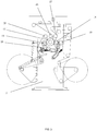
- the present invention includes a frame.
- the frame includes a first frame side 1, a second frame side 2 and a frame top 3 arranged on the top of the first frame side 1 and the second frame side 2.
- a first unwinding mechanism 4, a first unwinding tension device 5, a first coating channel tension-control pendulum roller device 6 and a coating mechanism 7 are arranged on the first frame side 1.
- a second unwinding mechanism 8, a rewinding mechanism 9, a material-pressing device 10, a second unwinding tension device 11 and a laminating device 12 are arranged on the second frame side 2.
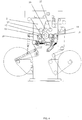
- the laminating device 12 includes a laminating cylinder 13, a first pressing rubber roller 14, a rubber roller bracer 15, a first rubber roller swing arm 16, a fixing fulcrum shaft 17, a back-up steel roller 18, a second pressing rubber roller 19, a back-up steel roller bracer 20, a first back-up steel roller swing arm 21, a second rubber roller swing arm 22, a return tension spring, a first cylinder 23, a second cylinder 24, a positioning flat pin, a rotary sleeve 35 and a positioning screw.
- the laminating cylinder 13 is connected with the second frame side 2.
- the first rubber roller swing arm 16 is fixed on both ends of the rubber roller bracer 15.
- the first pressing rubber roller 14 is mounted on the first rubber roller swing arm 16.
- the first back-up steel roller swing arm 21 is fixed on both ends of the back-up steel roller bracer 20.
- the first back-up steel roller 18 is mounted on the first back-up steel roller swing arm 21.
- the fixing fulcrum shaft 17 is connected with the first back-up steel roller swing arm 21 through the first rubber roller swing arm 16.
- the ends of the first fixing fulcrum shaft 17 are fixed on the second frame side 2.
- the first rubber roller swing arm 16 and the first back-up steel roller swing arm 21 are rotatable on the fixing fulcrum shaft 17.
- the first rubber roller swing arm 16 is connected with the first back-up steel roller swing arm 21 by the return tension spring.
- One end of the first cylinder 23 is fixed on the second frame side 2.
- the other end of the first cylinder 23 is connected with the first back-up steel roller swing arm 21.
- One end of the second cylinder 24 is fixed on the second frame side 2.
- the other end of the second cylinder 24 is connected with the second rubber roller swing arm 22.
- the second pressing rubber roller 19 is mounted on the second rubber roller swing arm 22.
- the said second pressing rubber roller 19 is at the left end of the laminating cylinder 13.
- the said first back-up steel roller 18 and the first pressing rubber roller 14 are at the right end of the laminating cylinder 13.
- the rotary sleeve 35 is mounted on the first rubber roller swing arm 16.
- the positioning flat pin is mounted within the rotary sleeve 35. There are more than two positioning grooves arranged on the rotary sleeve 35.
- the positioning screw is arranged on the first rubber roller swing arm 16 and engaged with the positioning grooves.
- a first guide roller 25, a second guide roller 26 and a third guide roller 27 are arranged above the first back-up steel roller 18, the laminating cylinder 13, the first pressing rubber roller 14 and the second pressing rubber roller 19 in order from left to right.
- a fourth guide roller 28 is arranged below the laminating cylinder 13.
- the said material-pressing device 10 includes a material-pressing holder 29 and a material-pressing rod 30.
- a material-pressing roller 31 is arranged on one end of the material-pressing rod 30.
- the other end of the material-pressing rod 30 is hinged with the second frame side 2.
- the material-pressing holder 29 is connected with the second frame side 2.
- a material-pressing cylinder 32 is hinged on the material-pressing holder 29. There are a number of positioning holes 33 arranged on the material-pressing rod 30. The driving end of the material-pressing cylinder 32 is connected with one of the positioning holes 33. There are a number of wide slot two-way partial guide roller 34 arranged on the first frame side 1, the second frame side 2 and the frame top 3.
- a forward single laminating process, a forward double laminating process and an inverse single laminating process could be realized with the multifunctional laminating machine, thereby meeting different demands in use.
- a first substrate material on a first unwinding device passes through a first pendulum roller device, the first unwinding tension device 5, the coating mechanism 7, the first coating channel tension-control pendulum roller device 6 and the second guide roller 26 in turn, and then it enters the right side of the steal roller 13 of the laminating device 12;
- a second substrate material on a second unwinding device passes through the second unwinding tension device 11 and the third guide roller 27 in turn, and then it enters the right side of the laminating cylinder 13 of the laminating device 12.
- the first substrate material and the second substrate material are laminated at the laminating device 12, and then a rewinding is accomplished at a rewinding device.
- a first substrate material on a first unwinding device passes through a first pendulum roller device, the first unwinding tension device 5, the coating mechanism 7, the first coating channel tension-control pendulum roller device 6 and the second guide roller 26 in turn, and then it enters the right side of the laminating cylinder 13 of the laminating device 12.
- a second substrate material on a second unwinding device passes through the second unwinding tension device 11 and the third guide roller 27 in turn, and then it enters the right side of the laminating cylinder 13 of the laminating device 12.
- the first substrate material and the second substrate material are laminated at the right side of the laminating device 12 for the first time, and they are laminated at the left side of the laminating device 12 for the second time. Then a rewinding is accomplished at a rewinding device after they pass through the first guide roller 25.
- the problem of a non-uniform glue layer caused by a non-uniform printing film, by an insufficient leveling of the glue or by some defects existing on the first pressing rubber roller 14 could be solved through two laminating processes with the first pressing rubber roller 14 and the second pressing rubber roller 19. As a result, a double insurance effect could be realized.
- a first substrate material on a first unwinding device passes through a first pendulum roller device, the first unwinding tension device 5, the coating mechanism 7, the first coating channel tension-control pendulum roller device 6 and the second guide roller 26 in turn, and then it enters the left side of the laminating cylinder 13 of the laminating device 12.
- a second substrate material on a second unwinding device passes through the second unwinding tension device 11 and the third guide roller 27 in turn, and then it enters the left side of the laminating cylinder 13 of the laminating device 12. Make the laminating cylinder 13 and the second pressing rubber roller 19 rotate in opposite direction.
- the first substrate material and the second substrate material are laminated at the left side of the laminating device 12 and pass through the fourth guide roller 28, and then a rewinding is accomplished at a rewinding device.
- the base material on the second unwinding mechanism 8 is aluminum foil
- the unevenness existing on the film of the first unwinding mechanism 4 can be passed to the aluminum foil by contacting with the laminating cylinder 13.
- this unevenness on the aluminum foil could be solved by the inverse single laminating process.
- the present invention further comprises a laminating method of the multifunctional laminating machine comprising: a forward single laminating process, a forward double laminating process and an inverse single laminating process.
- the forward single laminating process comprising the following steps:
- the forward double laminating process comprising the following steps:
- the inverse single laminating process comprising the following steps:
Landscapes
- Physics & Mathematics (AREA)
- Fluid Mechanics (AREA)
- Lining Or Joining Of Plastics Or The Like (AREA)
- Coating Apparatus (AREA)
- Application Of Or Painting With Fluid Materials (AREA)
Claims (5)
- Une machine de stratification multifonctionnelle, caractérisée en ce qu'elle comprend un cadre, le cadre comprenant un premier côté de cadre (1), un deuxième côté de cadre (2), et un dessus de cadre (3) disposé sur le dessus du premier côté de cadre (1) et du deuxième côté de cadre (2) ;un premier mécanisme de déroulement (4), un premier dispositif de tension de déroulement (5), un premier dispositif de rouleau pendulaire de contrôle de la tension du canal de revêtement (6) et un mécanisme de revêtement (7) étant disposés sur le premier côté du cadre (1) ;un deuxième mécanisme de déroulement (8), un mécanisme de rembobinage (9), un dispositif de pressage de matériau (10), un deuxième dispositif de tension de déroulement (11), et un dispositif de stratification (12) étant disposés sur le deuxième côté du cadre ;le dispositif de stratification (12) comprenant un cylindre de stratification (13), un premier rouleau en caoutchouc de pression (14), une entretoise de rouleau en caoutchouc (15), un premier bras oscillant de rouleau en caoutchouc (16), un arbre de pivotement de fixation (17), un premier rouleau en acier d'appui (18), un deuxième rouleau en caoutchouc de pression (19), une entretoise de rouleau en acier d'appui (20), un premier bras oscillant de rouleau en acier d'appui (21), un deuxième bras oscillant de rouleau en caoutchouc (22), un ressort de tension de rappel, un premier cylindre (23), et un deuxième cylindre (24), le cylindre de stratification (13) étant relié au deuxième côté du cadre (2), le premier bras oscillant de rouleau en caoutchouc (16) étant fixé sur les deux extrémités de l'entretoise de rouleau en caoutchouc (15), le premier rouleau en caoutchouc de pression (14) étant monté sur le premier bras oscillant de rouleau en caoutchouc (16), le premier bras oscillant de rouleau en acier d'appui (21) étant fixé sur les deux extrémités de l'entretoise de rouleau en acier d'appui (20), le premier rouleau en acier d'appui (18) étant monté sur le premier bras oscillant de rouleau en acier d'appui (21), l'arbre de pivotement de fixation (17) étant relié au premier bras oscillant de rouleau en acier d'appui (21) par l'intermédiaire du premier bras oscillant de rouleau en caoutchouc (16), les extrémités du premier arbre de pivotement de fixation (17) étant fixées sur le deuxième côté du cadre (2), le premier bras oscillant de rouleau en caoutchouc (16) et le premier bras oscillant de rouleau en acier d'appui (21) pouvant tourner sur l'arbre de pivotement de fixation (17), le premier bras oscillant de rouleau en caoutchouc (16) étant relié au premier bras oscillant de rouleau en acier d'appui (21) par le ressort de tension de rappel, une extrémité du premier cylindre (23) étant fixée sur le deuxième côté du cadre (2), l'autre extrémité du premier cylindre (23) étant reliée au premier bras oscillant de rouleau en acier d'appui (21), une extrémité du deuxième cylindre (24) étant fixée sur le deuxième côté du cadre (2), l'autre extrémité du deuxième cylindre (24) étant reliée au deuxième bras oscillant de rouleau en caoutchouc (22), le deuxième rouleau en caoutchouc de pression (19) étant monté sur le deuxième bras oscillant de rouleau en caoutchouc (22), le deuxième rouleau en caoutchouc de pression (19) étant à l'extrémité gauche du cylindre de stratification (13), le premier rouleau en acier d'appui (18) et le premier rouleau en caoutchouc de pression (14) étant à l'extrémité droite du cylindre de stratification (13) ; un premier rouleau de guidage (25), un deuxième rouleau de guidage (26), et un troisième rouleau de guidage (27) étant disposés au-dessus du premier rouleau en acier d'appui (18), du cylindre de stratification (13), du premier rouleau en caoutchouc de pression (14) et du deuxième rouleau en caoutchouc de pression (19) dans l'ordre de gauche à droite, un quatrième rouleau de guidage (28) étant disposé sous le cylindre de stratification (13).
- La machine de stratification multifonctionnelle selon la revendication 1, caractérisée en ce que le dispositif de stratification (12) comprend en outre une broche plate de positionnement, un manchon rotatif (35), et une vis de positionnement, le manchon rotatif (35) étant monté sur le premier bras oscillant de rouleau en caoutchouc (16), la broche plate de positionnement étant montée dans le manchon rotatif (35), plus de deux rainures de positionnement étant disposées sur le manchon rotatif, la vis de positionnement étant disposée sur le premier bras oscillant de rouleau en caoutchouc (16) et engagée avec les rainures de positionnement.
- La machine de stratification multifonctionnelle selon la revendication 1, caractérisée en ce que le dispositif de pressage de matériau (1) comprend un support de pressage de matériau (29) et une tige de pressage de matériau (30),
un rouleau de pressage de matériau (31) étant disposé sur une extrémité de la tige de pressage de matériau (30), l'autre extrémité de la tige de pressage de matériau (30) étant articulée avec le deuxième côté du cadre (2), le support de pressage de matériau (29) étant relié au deuxième côté du cadre (2), un cylindre de pressage de matériau (32) étant articulé sur le support de pressage de matériau (29), un certain nombre de trous de positionnement (33) étant disposés sur la tige de pressage de matériau (30), l'extrémité d'entraînement du cylindre de pressage de matériau (32) étant reliée à l'un des trous de positionnement (33). - La machine de stratification multifonctionnelle selon la revendication 1, caractérisée en ce qu'un certain nombre de rouleaux de guidage partiels bidirectionnels à fente large (34) sont disposés sur le premier côté du cadre (1), le deuxième côté du cadre (2), et le dessus du cadre (3).
- Un procédé de stratification de la machine de stratification multifonctionnelle caractérisé en ce que le procédé comprend un procédé de stratification simple avant, un procédé de stratification double avant et un procédé de stratification simple inverse ;le procédé de stratification simple avant comprenant les étapes suivantes :A1. faire passer un premier matériau de substrat sur un premier dispositif de déroulement à travers un premier dispositif de rouleau pendulaire, un premier dispositif de tension de déroulement (5), un mécanisme de revêtement (7), un premier dispositif de rouleau pendulaire de contrôle de la tension du canal de revêtement et un deuxième rouleau de guidage (26) tour à tour, puis le faire entrer dans le côté droit d'un cylindre de stratification (13) d'un dispositif de stratification (12) ;B1. faire passer un deuxième matériau de substrat sur un deuxième dispositif de déroulement à travers un deuxième dispositif de tension de déroulement (11) et un troisième rouleau de guidage (27) tour à tour, puis le faire entrer dans le côté droit du cylindre de stratification (13) du dispositif de stratification (12) ;C1. réaliser un rembobinage au niveau d'un dispositif de rembobinage après que le premier matériau de substrat et le deuxième matériau de substrat ont été stratifiés au niveau du dispositif de stratification (12) ;le procédé de stratification double avant comprenant les étapes suivantes :A2. faire passer un premier matériau de substrat sur un premier dispositif de déroulement à travers un premier dispositif de rouleau pendulaire, un premier dispositif de tension de déroulement (5), un mécanisme de revêtement (7), un premier dispositif de rouleau pendulaire de contrôle de la tension du canal de revêtement (6), et un deuxième rouleau de guidage (26) tour à tour, puis le faire entrer dans le côté droit d'un cylindre de stratification (13) d'un dispositif de stratification (12) ;B2. faire passer un deuxième matériau de substrat sur un deuxième dispositif de déroulement à travers un deuxième dispositif de tension de déroulement (11) et un troisième rouleau de guidage (27) tour à tour, puis le faire entrer dans le côté droit du cylindre de stratification (13) du dispositif de stratification (12) ;C2. stratifier le premier matériau de substrat et le deuxième matériau de substrat pour la première fois au niveau du côté gauche du dispositif de stratification (12) et les stratifier pour la deuxième fois au niveau du côté droit du dispositif de stratification, puis réaliser un rembobinage au niveau d'un dispositif de rembobinage après leur passage à travers un premier rouleau de guidage (25) ;le procédé de stratification simple inverse comprenant les étapes suivantes :A3. faire passer un premier matériau de substrat sur un premier dispositif de déroulement à travers un premier dispositif de rouleau pendulaire, un premier dispositif de tension de déroulement (5), un mécanisme de revêtement (7), un premier dispositif de rouleau pendulaire de contrôle de la tension du canal de revêtement (6), et un deuxième rouleau de guidage (26) tour à tour, puis le faire entrer dans le côté gauche d'un cylindre de stratification (13) d'un dispositif de stratification (12) ;B3. faire passer un deuxième matériau de substrat sur un deuxième dispositif de déroulement à travers un deuxième dispositif de tension de déroulement (11) et un troisième rouleau de guidage (27) tour à tour, puis le faire entrer dans le côté gauche du cylindre de stratification (13) du dispositif de stratification (12) ;C3. faire tourner le cylindre de stratification (13) et le deuxième rouleau en caoutchouc de pression (19) dans des directions opposées, stratifier le premier matériau de substrat et le deuxième matériau de substrat au niveau du côté gauche du dispositif de stratification (12), puis réaliser un rembobinage au niveau d'un dispositif de rembobinage après leur passage à travers un quatrième rouleau de guidage (28).
Priority Applications (1)
| Application Number | Priority Date | Filing Date | Title |
|---|---|---|---|
| PL18803519T PL3536498T3 (pl) | 2018-01-19 | 2018-03-12 | Maszyna wielofunkcyjna do laminowania i sposób laminowania |
Applications Claiming Priority (2)
| Application Number | Priority Date | Filing Date | Title |
|---|---|---|---|
| CN201810053573.9A CN108099352A (zh) | 2018-01-19 | 2018-01-19 | 一种多功能复合机及其复合方法 |
| PCT/CN2018/078694 WO2019140766A1 (fr) | 2018-01-19 | 2018-03-12 | Machine composite multifonction et son procédé composite |
Publications (3)
| Publication Number | Publication Date |
|---|---|
| EP3536498A1 EP3536498A1 (fr) | 2019-09-11 |
| EP3536498A4 EP3536498A4 (fr) | 2020-02-26 |
| EP3536498B1 true EP3536498B1 (fr) | 2021-09-22 |
Family
ID=62220043
Family Applications (1)
| Application Number | Title | Priority Date | Filing Date |
|---|---|---|---|
| EP18803519.0A Active EP3536498B1 (fr) | 2018-01-19 | 2018-03-12 | Machine à laminer multifonction et procédé de laminage |
Country Status (5)
| Country | Link |
|---|---|
| EP (1) | EP3536498B1 (fr) |
| CN (1) | CN108099352A (fr) |
| ES (1) | ES2901472T3 (fr) |
| PL (1) | PL3536498T3 (fr) |
| WO (1) | WO2019140766A1 (fr) |
Families Citing this family (6)
| Publication number | Priority date | Publication date | Assignee | Title |
|---|---|---|---|---|
| CN109334210B (zh) * | 2018-11-21 | 2024-07-30 | 广州通泽机械有限公司 | 一种可变路径、基准和驱动关系的复合工艺及复合单元 |
| CN110901213A (zh) * | 2019-12-18 | 2020-03-24 | 辛格顿(常州)新材料科技有限公司 | 压敏胶贴合装置及贴合方法 |
| CN111331997B (zh) * | 2020-04-16 | 2022-05-27 | 广州通泽机械有限公司 | 一种三合一无溶剂复合机及复合方法 |
| CN114043806A (zh) * | 2021-10-27 | 2022-02-15 | 洛阳帝然特医药包装材料有限公司 | 一种医用包装铝箔的生产装置 |
| CN114030265A (zh) * | 2021-12-03 | 2022-02-11 | 广东厚海环保新材料有限公司 | 无纺布三合一涂胶复合机 |
| CN119952959B (zh) * | 2023-11-08 | 2025-11-28 | 厦门文仪电脑材料有限公司 | 一种膜复合机构 |
Family Cites Families (8)
| Publication number | Priority date | Publication date | Assignee | Title |
|---|---|---|---|---|
| US6912040B2 (en) * | 2003-04-30 | 2005-06-28 | Hewlett-Packard Development Company, Lp. | Photofinishers |
| CN101259772B (zh) * | 2008-04-29 | 2010-06-09 | 广州通泽机械有限公司 | 无溶剂复合机 |
| CN205522870U (zh) * | 2016-04-08 | 2016-08-31 | 浙江绿净环保科技有限公司 | 一种高效聚四氟乙烯层压复合装置 |
| CN106183349B (zh) * | 2016-08-30 | 2018-11-02 | 广州通泽机械有限公司 | 一种双模式涂布无溶剂复合机及双模式涂布无溶剂复合单元 |
| CN206456063U (zh) * | 2016-10-21 | 2017-09-01 | 广东恒生彩印有限公司机械分公司 | 一种软包装快干型自动裁切无溶剂复合设备 |
| CN107244131A (zh) * | 2017-06-06 | 2017-10-13 | 上海大城包装材料有限公司 | 一种新型无溶剂两用复合机 |
| CN107283997A (zh) * | 2017-08-04 | 2017-10-24 | 广州通泽机械有限公司 | 一种四层复合机 |
| CN107498980B (zh) * | 2017-09-18 | 2020-02-28 | 广州通泽机械有限公司 | 一种双涂型无溶剂复合机及其复合方法 |
-
2018
- 2018-01-19 CN CN201810053573.9A patent/CN108099352A/zh active Pending
- 2018-03-12 WO PCT/CN2018/078694 patent/WO2019140766A1/fr not_active Ceased
- 2018-03-12 PL PL18803519T patent/PL3536498T3/pl unknown
- 2018-03-12 EP EP18803519.0A patent/EP3536498B1/fr active Active
- 2018-03-12 ES ES18803519T patent/ES2901472T3/es active Active
Also Published As
| Publication number | Publication date |
|---|---|
| EP3536498A4 (fr) | 2020-02-26 |
| WO2019140766A1 (fr) | 2019-07-25 |
| PL3536498T3 (pl) | 2022-04-04 |
| ES2901472T3 (es) | 2022-03-22 |
| CN108099352A (zh) | 2018-06-01 |
| EP3536498A1 (fr) | 2019-09-11 |
Similar Documents
| Publication | Publication Date | Title |
|---|---|---|
| EP3536498B1 (fr) | Machine à laminer multifonction et procédé de laminage | |
| CN205818608U (zh) | 卷对卷双面覆膜机 | |
| KR20130019298A (ko) | 롤투롤 인쇄 시스템 | |
| CN109955311A (zh) | 一种铜箔裁切机 | |
| CN219303722U (zh) | 一种包膜工装 | |
| CN111392473B (zh) | 一种柔印机自动换卷连续覆膜设备 | |
| WO2019058756A1 (fr) | Système de traitement de bande et procédé de commande | |
| CN110254875A (zh) | 高效卡纸贴标设备 | |
| KR102035026B1 (ko) | 기능성 필름 부착장치 | |
| CN204093673U (zh) | 一种涂布机 | |
| CN207908834U (zh) | 一种偏光片贴附装置 | |
| CN104139601A (zh) | 一种卷筒纸印刷装置 | |
| CN201989390U (zh) | 一种卷材覆合装置 | |
| CN211756602U (zh) | 一种涂布机涂布结构 | |
| CN206485030U (zh) | 一种贴胶治具 | |
| KR20190104083A (ko) | 임프린팅 장치 및 이를 이용한 임프린팅 방법 | |
| KR102148674B1 (ko) | 기능성 필름 부착시스템 | |
| CN207643693U (zh) | 间隙可调的透气膜拉伸辊装置 | |
| CN211165760U (zh) | 开窗牛皮纸无溶剂复合机 | |
| WO2024229911A1 (fr) | Mécanisme d'ajustement et d'aplatissement pour film d'enroulement | |
| CN103950283B (zh) | 一种印刷机联机冷烫用跳步装置 | |
| CN206763283U (zh) | 一种涂布机双面涂布快速切换装置 | |
| CN219560212U (zh) | 一种六辊涂布机构及其复合机 | |
| CN110561886A (zh) | 开窗牛皮纸无溶剂复合机 | |
| CN216889347U (zh) | 一种张力释放机构和贴合装置 |
Legal Events
| Date | Code | Title | Description |
|---|---|---|---|
| STAA | Information on the status of an ep patent application or granted ep patent |
Free format text: STATUS: UNKNOWN |
|
| STAA | Information on the status of an ep patent application or granted ep patent |
Free format text: STATUS: THE INTERNATIONAL PUBLICATION HAS BEEN MADE |
|
| PUAI | Public reference made under article 153(3) epc to a published international application that has entered the european phase |
Free format text: ORIGINAL CODE: 0009012 |
|
| STAA | Information on the status of an ep patent application or granted ep patent |
Free format text: STATUS: REQUEST FOR EXAMINATION WAS MADE |
|
| 17P | Request for examination filed |
Effective date: 20181127 |
|
| AK | Designated contracting states |
Kind code of ref document: A1 Designated state(s): AL AT BE BG CH CY CZ DE DK EE ES FI FR GB GR HR HU IE IS IT LI LT LU LV MC MK MT NL NO PL PT RO RS SE SI SK SM TR |
|
| AX | Request for extension of the european patent |
Extension state: BA ME |
|
| A4 | Supplementary search report drawn up and despatched |
Effective date: 20200127 |
|
| RIC1 | Information provided on ipc code assigned before grant |
Ipc: B32B 37/10 20060101AFI20200121BHEP Ipc: B32B 37/20 20060101ALN20200121BHEP Ipc: B32B 41/00 20060101ALI20200121BHEP |
|
| RIC1 | Information provided on ipc code assigned before grant |
Ipc: B32B 37/10 20060101AFI20210202BHEP Ipc: B32B 37/20 20060101ALN20210202BHEP Ipc: B32B 41/00 20060101ALI20210202BHEP |
|
| GRAP | Despatch of communication of intention to grant a patent |
Free format text: ORIGINAL CODE: EPIDOSNIGR1 |
|
| STAA | Information on the status of an ep patent application or granted ep patent |
Free format text: STATUS: GRANT OF PATENT IS INTENDED |
|
| DAV | Request for validation of the european patent (deleted) | ||
| DAX | Request for extension of the european patent (deleted) | ||
| INTG | Intention to grant announced |
Effective date: 20210315 |
|
| RIC1 | Information provided on ipc code assigned before grant |
Ipc: B32B 37/10 20060101AFI20210301BHEP Ipc: B32B 37/20 20060101ALN20210301BHEP Ipc: B32B 41/00 20060101ALI20210301BHEP |
|
| GRAJ | Information related to disapproval of communication of intention to grant by the applicant or resumption of examination proceedings by the epo deleted |
Free format text: ORIGINAL CODE: EPIDOSDIGR1 |
|
| STAA | Information on the status of an ep patent application or granted ep patent |
Free format text: STATUS: REQUEST FOR EXAMINATION WAS MADE |
|
| RIN1 | Information on inventor provided before grant (corrected) |
Inventor name: LI, JUNHONG |
|
| GRAP | Despatch of communication of intention to grant a patent |
Free format text: ORIGINAL CODE: EPIDOSNIGR1 |
|
| STAA | Information on the status of an ep patent application or granted ep patent |
Free format text: STATUS: GRANT OF PATENT IS INTENDED |
|
| INTC | Intention to grant announced (deleted) | ||
| RIC1 | Information provided on ipc code assigned before grant |
Ipc: B32B 37/20 20060101ALN20210527BHEP Ipc: B32B 41/00 20060101ALI20210527BHEP Ipc: B32B 37/10 20060101AFI20210527BHEP |
|
| INTG | Intention to grant announced |
Effective date: 20210610 |
|
| GRAS | Grant fee paid |
Free format text: ORIGINAL CODE: EPIDOSNIGR3 |
|
| GRAA | (expected) grant |
Free format text: ORIGINAL CODE: 0009210 |
|
| STAA | Information on the status of an ep patent application or granted ep patent |
Free format text: STATUS: THE PATENT HAS BEEN GRANTED |
|
| AK | Designated contracting states |
Kind code of ref document: B1 Designated state(s): AL AT BE BG CH CY CZ DE DK EE ES FI FR GB GR HR HU IE IS IT LI LT LU LV MC MK MT NL NO PL PT RO RS SE SI SK SM TR |
|
| REG | Reference to a national code |
Ref country code: GB Ref legal event code: FG4D |
|
| REG | Reference to a national code |
Ref country code: IE Ref legal event code: FG4D |
|
| REG | Reference to a national code |
Ref country code: DE Ref legal event code: R096 Ref document number: 602018024040 Country of ref document: DE |
|
| REG | Reference to a national code |
Ref country code: CH Ref legal event code: EP Ref country code: AT Ref legal event code: REF Ref document number: 1432002 Country of ref document: AT Kind code of ref document: T Effective date: 20211015 |
|
| REG | Reference to a national code |
Ref country code: LT Ref legal event code: MG9D |
|
| REG | Reference to a national code |
Ref country code: NL Ref legal event code: MP Effective date: 20210922 |
|
| PG25 | Lapsed in a contracting state [announced via postgrant information from national office to epo] |
Ref country code: RS Free format text: LAPSE BECAUSE OF FAILURE TO SUBMIT A TRANSLATION OF THE DESCRIPTION OR TO PAY THE FEE WITHIN THE PRESCRIBED TIME-LIMIT Effective date: 20210922 Ref country code: SE Free format text: LAPSE BECAUSE OF FAILURE TO SUBMIT A TRANSLATION OF THE DESCRIPTION OR TO PAY THE FEE WITHIN THE PRESCRIBED TIME-LIMIT Effective date: 20210922 Ref country code: HR Free format text: LAPSE BECAUSE OF FAILURE TO SUBMIT A TRANSLATION OF THE DESCRIPTION OR TO PAY THE FEE WITHIN THE PRESCRIBED TIME-LIMIT Effective date: 20210922 Ref country code: FI Free format text: LAPSE BECAUSE OF FAILURE TO SUBMIT A TRANSLATION OF THE DESCRIPTION OR TO PAY THE FEE WITHIN THE PRESCRIBED TIME-LIMIT Effective date: 20210922 Ref country code: LT Free format text: LAPSE BECAUSE OF FAILURE TO SUBMIT A TRANSLATION OF THE DESCRIPTION OR TO PAY THE FEE WITHIN THE PRESCRIBED TIME-LIMIT Effective date: 20210922 Ref country code: BG Free format text: LAPSE BECAUSE OF FAILURE TO SUBMIT A TRANSLATION OF THE DESCRIPTION OR TO PAY THE FEE WITHIN THE PRESCRIBED TIME-LIMIT Effective date: 20211222 Ref country code: NO Free format text: LAPSE BECAUSE OF FAILURE TO SUBMIT A TRANSLATION OF THE DESCRIPTION OR TO PAY THE FEE WITHIN THE PRESCRIBED TIME-LIMIT Effective date: 20211222 |
|
| REG | Reference to a national code |
Ref country code: AT Ref legal event code: MK05 Ref document number: 1432002 Country of ref document: AT Kind code of ref document: T Effective date: 20210922 |
|
| PG25 | Lapsed in a contracting state [announced via postgrant information from national office to epo] |
Ref country code: LV Free format text: LAPSE BECAUSE OF FAILURE TO SUBMIT A TRANSLATION OF THE DESCRIPTION OR TO PAY THE FEE WITHIN THE PRESCRIBED TIME-LIMIT Effective date: 20210922 Ref country code: GR Free format text: LAPSE BECAUSE OF FAILURE TO SUBMIT A TRANSLATION OF THE DESCRIPTION OR TO PAY THE FEE WITHIN THE PRESCRIBED TIME-LIMIT Effective date: 20211223 |
|
| REG | Reference to a national code |
Ref country code: ES Ref legal event code: FG2A Ref document number: 2901472 Country of ref document: ES Kind code of ref document: T3 Effective date: 20220322 |
|
| PG25 | Lapsed in a contracting state [announced via postgrant information from national office to epo] |
Ref country code: AT Free format text: LAPSE BECAUSE OF FAILURE TO SUBMIT A TRANSLATION OF THE DESCRIPTION OR TO PAY THE FEE WITHIN THE PRESCRIBED TIME-LIMIT Effective date: 20210922 |
|
| PG25 | Lapsed in a contracting state [announced via postgrant information from national office to epo] |
Ref country code: IS Free format text: LAPSE BECAUSE OF FAILURE TO SUBMIT A TRANSLATION OF THE DESCRIPTION OR TO PAY THE FEE WITHIN THE PRESCRIBED TIME-LIMIT Effective date: 20220122 Ref country code: SK Free format text: LAPSE BECAUSE OF FAILURE TO SUBMIT A TRANSLATION OF THE DESCRIPTION OR TO PAY THE FEE WITHIN THE PRESCRIBED TIME-LIMIT Effective date: 20210922 Ref country code: RO Free format text: LAPSE BECAUSE OF FAILURE TO SUBMIT A TRANSLATION OF THE DESCRIPTION OR TO PAY THE FEE WITHIN THE PRESCRIBED TIME-LIMIT Effective date: 20210922 Ref country code: PT Free format text: LAPSE BECAUSE OF FAILURE TO SUBMIT A TRANSLATION OF THE DESCRIPTION OR TO PAY THE FEE WITHIN THE PRESCRIBED TIME-LIMIT Effective date: 20220124 Ref country code: NL Free format text: LAPSE BECAUSE OF FAILURE TO SUBMIT A TRANSLATION OF THE DESCRIPTION OR TO PAY THE FEE WITHIN THE PRESCRIBED TIME-LIMIT Effective date: 20210922 Ref country code: EE Free format text: LAPSE BECAUSE OF FAILURE TO SUBMIT A TRANSLATION OF THE DESCRIPTION OR TO PAY THE FEE WITHIN THE PRESCRIBED TIME-LIMIT Effective date: 20210922 Ref country code: CZ Free format text: LAPSE BECAUSE OF FAILURE TO SUBMIT A TRANSLATION OF THE DESCRIPTION OR TO PAY THE FEE WITHIN THE PRESCRIBED TIME-LIMIT Effective date: 20210922 Ref country code: AL Free format text: LAPSE BECAUSE OF FAILURE TO SUBMIT A TRANSLATION OF THE DESCRIPTION OR TO PAY THE FEE WITHIN THE PRESCRIBED TIME-LIMIT Effective date: 20210922 |
|
| REG | Reference to a national code |
Ref country code: DE Ref legal event code: R097 Ref document number: 602018024040 Country of ref document: DE |
|
| PG25 | Lapsed in a contracting state [announced via postgrant information from national office to epo] |
Ref country code: DK Free format text: LAPSE BECAUSE OF FAILURE TO SUBMIT A TRANSLATION OF THE DESCRIPTION OR TO PAY THE FEE WITHIN THE PRESCRIBED TIME-LIMIT Effective date: 20210922 |
|
| PLBE | No opposition filed within time limit |
Free format text: ORIGINAL CODE: 0009261 |
|
| STAA | Information on the status of an ep patent application or granted ep patent |
Free format text: STATUS: NO OPPOSITION FILED WITHIN TIME LIMIT |
|
| 26N | No opposition filed |
Effective date: 20220623 |
|
| PG25 | Lapsed in a contracting state [announced via postgrant information from national office to epo] |
Ref country code: MC Free format text: LAPSE BECAUSE OF FAILURE TO SUBMIT A TRANSLATION OF THE DESCRIPTION OR TO PAY THE FEE WITHIN THE PRESCRIBED TIME-LIMIT Effective date: 20210922 |
|
| REG | Reference to a national code |
Ref country code: CH Ref legal event code: PL |
|
| GBPC | Gb: european patent ceased through non-payment of renewal fee |
Effective date: 20220312 |
|
| PG25 | Lapsed in a contracting state [announced via postgrant information from national office to epo] |
Ref country code: SI Free format text: LAPSE BECAUSE OF FAILURE TO SUBMIT A TRANSLATION OF THE DESCRIPTION OR TO PAY THE FEE WITHIN THE PRESCRIBED TIME-LIMIT Effective date: 20210922 |
|
| REG | Reference to a national code |
Ref country code: BE Ref legal event code: MM Effective date: 20220331 |
|
| PG25 | Lapsed in a contracting state [announced via postgrant information from national office to epo] |
Ref country code: LU Free format text: LAPSE BECAUSE OF NON-PAYMENT OF DUE FEES Effective date: 20220312 Ref country code: LI Free format text: LAPSE BECAUSE OF NON-PAYMENT OF DUE FEES Effective date: 20220331 Ref country code: IE Free format text: LAPSE BECAUSE OF NON-PAYMENT OF DUE FEES Effective date: 20220312 Ref country code: GB Free format text: LAPSE BECAUSE OF NON-PAYMENT OF DUE FEES Effective date: 20220312 Ref country code: FR Free format text: LAPSE BECAUSE OF NON-PAYMENT OF DUE FEES Effective date: 20220331 Ref country code: CH Free format text: LAPSE BECAUSE OF NON-PAYMENT OF DUE FEES Effective date: 20220331 |
|
| PG25 | Lapsed in a contracting state [announced via postgrant information from national office to epo] |
Ref country code: BE Free format text: LAPSE BECAUSE OF NON-PAYMENT OF DUE FEES Effective date: 20220331 |
|
| PG25 | Lapsed in a contracting state [announced via postgrant information from national office to epo] |
Ref country code: SM Free format text: LAPSE BECAUSE OF FAILURE TO SUBMIT A TRANSLATION OF THE DESCRIPTION OR TO PAY THE FEE WITHIN THE PRESCRIBED TIME-LIMIT Effective date: 20210922 Ref country code: MK Free format text: LAPSE BECAUSE OF FAILURE TO SUBMIT A TRANSLATION OF THE DESCRIPTION OR TO PAY THE FEE WITHIN THE PRESCRIBED TIME-LIMIT Effective date: 20210922 Ref country code: CY Free format text: LAPSE BECAUSE OF FAILURE TO SUBMIT A TRANSLATION OF THE DESCRIPTION OR TO PAY THE FEE WITHIN THE PRESCRIBED TIME-LIMIT Effective date: 20210922 |
|
| PG25 | Lapsed in a contracting state [announced via postgrant information from national office to epo] |
Ref country code: HU Free format text: LAPSE BECAUSE OF FAILURE TO SUBMIT A TRANSLATION OF THE DESCRIPTION OR TO PAY THE FEE WITHIN THE PRESCRIBED TIME-LIMIT; INVALID AB INITIO Effective date: 20180312 |
|
| PG25 | Lapsed in a contracting state [announced via postgrant information from national office to epo] |
Ref country code: TR Free format text: LAPSE BECAUSE OF FAILURE TO SUBMIT A TRANSLATION OF THE DESCRIPTION OR TO PAY THE FEE WITHIN THE PRESCRIBED TIME-LIMIT Effective date: 20210922 |
|
| PG25 | Lapsed in a contracting state [announced via postgrant information from national office to epo] |
Ref country code: MT Free format text: LAPSE BECAUSE OF FAILURE TO SUBMIT A TRANSLATION OF THE DESCRIPTION OR TO PAY THE FEE WITHIN THE PRESCRIBED TIME-LIMIT Effective date: 20210922 |
|
| PGFP | Annual fee paid to national office [announced via postgrant information from national office to epo] |
Ref country code: DE Payment date: 20250318 Year of fee payment: 8 |
|
| PGFP | Annual fee paid to national office [announced via postgrant information from national office to epo] |
Ref country code: IT Payment date: 20250314 Year of fee payment: 8 |
|
| PGFP | Annual fee paid to national office [announced via postgrant information from national office to epo] |
Ref country code: ES Payment date: 20250409 Year of fee payment: 8 |
|
| PGFP | Annual fee paid to national office [announced via postgrant information from national office to epo] |
Ref country code: PL Payment date: 20260305 Year of fee payment: 9 |