EP3536485B1 - Apparatus for additively manufacturing three-dimensional objects - Google Patents
Apparatus for additively manufacturing three-dimensional objects Download PDFInfo
- Publication number
- EP3536485B1 EP3536485B1 EP18161072.6A EP18161072A EP3536485B1 EP 3536485 B1 EP3536485 B1 EP 3536485B1 EP 18161072 A EP18161072 A EP 18161072A EP 3536485 B1 EP3536485 B1 EP 3536485B1
- Authority
- EP
- European Patent Office
- Prior art keywords
- measurement
- build
- build plane
- build material
- energy beam
- Prior art date
- Legal status (The legal status is an assumption and is not a legal conclusion. Google has not performed a legal analysis and makes no representation as to the accuracy of the status listed.)
- Active
Links
Images


Classifications
-
- B—PERFORMING OPERATIONS; TRANSPORTING
- B29—WORKING OF PLASTICS; WORKING OF SUBSTANCES IN A PLASTIC STATE IN GENERAL
- B29C—SHAPING OR JOINING OF PLASTICS; SHAPING OF MATERIAL IN A PLASTIC STATE, NOT OTHERWISE PROVIDED FOR; AFTER-TREATMENT OF THE SHAPED PRODUCTS, e.g. REPAIRING
- B29C64/00—Additive manufacturing, i.e. manufacturing of three-dimensional [3D] objects by additive deposition, additive agglomeration or additive layering, e.g. by 3D printing, stereolithography or selective laser sintering
- B29C64/30—Auxiliary operations or equipment
- B29C64/386—Data acquisition or data processing for additive manufacturing
- B29C64/393—Data acquisition or data processing for additive manufacturing for controlling or regulating additive manufacturing processes
-
- B—PERFORMING OPERATIONS; TRANSPORTING
- B22—CASTING; POWDER METALLURGY
- B22F—WORKING METALLIC POWDER; MANUFACTURE OF ARTICLES FROM METALLIC POWDER; MAKING METALLIC POWDER; APPARATUS OR DEVICES SPECIALLY ADAPTED FOR METALLIC POWDER
- B22F10/00—Additive manufacturing of workpieces or articles from metallic powder
-
- B—PERFORMING OPERATIONS; TRANSPORTING
- B22—CASTING; POWDER METALLURGY
- B22F—WORKING METALLIC POWDER; MANUFACTURE OF ARTICLES FROM METALLIC POWDER; MAKING METALLIC POWDER; APPARATUS OR DEVICES SPECIALLY ADAPTED FOR METALLIC POWDER
- B22F12/00—Apparatus or devices specially adapted for additive manufacturing; Auxiliary means for additive manufacturing; Combinations of additive manufacturing apparatus or devices with other processing apparatus or devices
- B22F12/40—Radiation means
- B22F12/49—Scanners
-
- B—PERFORMING OPERATIONS; TRANSPORTING
- B22—CASTING; POWDER METALLURGY
- B22F—WORKING METALLIC POWDER; MANUFACTURE OF ARTICLES FROM METALLIC POWDER; MAKING METALLIC POWDER; APPARATUS OR DEVICES SPECIALLY ADAPTED FOR METALLIC POWDER
- B22F12/00—Apparatus or devices specially adapted for additive manufacturing; Auxiliary means for additive manufacturing; Combinations of additive manufacturing apparatus or devices with other processing apparatus or devices
- B22F12/90—Means for process control, e.g. cameras or sensors
-
- B—PERFORMING OPERATIONS; TRANSPORTING
- B23—MACHINE TOOLS; METAL-WORKING NOT OTHERWISE PROVIDED FOR
- B23K—SOLDERING OR UNSOLDERING; WELDING; CLADDING OR PLATING BY SOLDERING OR WELDING; CUTTING BY APPLYING HEAT LOCALLY, e.g. FLAME CUTTING; WORKING BY LASER BEAM
- B23K26/00—Working by laser beam, e.g. welding, cutting or boring
- B23K26/02—Positioning or observing the workpiece, e.g. with respect to the point of impact; Aligning, aiming or focusing the laser beam
- B23K26/03—Observing, e.g. monitoring, the workpiece
-
- B—PERFORMING OPERATIONS; TRANSPORTING
- B23—MACHINE TOOLS; METAL-WORKING NOT OTHERWISE PROVIDED FOR
- B23K—SOLDERING OR UNSOLDERING; WELDING; CLADDING OR PLATING BY SOLDERING OR WELDING; CUTTING BY APPLYING HEAT LOCALLY, e.g. FLAME CUTTING; WORKING BY LASER BEAM
- B23K26/00—Working by laser beam, e.g. welding, cutting or boring
- B23K26/02—Positioning or observing the workpiece, e.g. with respect to the point of impact; Aligning, aiming or focusing the laser beam
- B23K26/03—Observing, e.g. monitoring, the workpiece
- B23K26/032—Observing, e.g. monitoring, the workpiece using optical means
-
- B—PERFORMING OPERATIONS; TRANSPORTING
- B23—MACHINE TOOLS; METAL-WORKING NOT OTHERWISE PROVIDED FOR
- B23K—SOLDERING OR UNSOLDERING; WELDING; CLADDING OR PLATING BY SOLDERING OR WELDING; CUTTING BY APPLYING HEAT LOCALLY, e.g. FLAME CUTTING; WORKING BY LASER BEAM
- B23K26/00—Working by laser beam, e.g. welding, cutting or boring
- B23K26/34—Laser welding for purposes other than joining
- B23K26/342—Build-up welding
-
- B—PERFORMING OPERATIONS; TRANSPORTING
- B28—WORKING CEMENT, CLAY, OR STONE
- B28B—SHAPING CLAY OR OTHER CERAMIC COMPOSITIONS; SHAPING SLAG; SHAPING MIXTURES CONTAINING CEMENTITIOUS MATERIAL, e.g. PLASTER
- B28B1/00—Producing shaped prefabricated articles from the material
- B28B1/001—Rapid manufacturing of 3D objects by additive depositing, agglomerating or laminating of material
-
- B—PERFORMING OPERATIONS; TRANSPORTING
- B29—WORKING OF PLASTICS; WORKING OF SUBSTANCES IN A PLASTIC STATE IN GENERAL
- B29C—SHAPING OR JOINING OF PLASTICS; SHAPING OF MATERIAL IN A PLASTIC STATE, NOT OTHERWISE PROVIDED FOR; AFTER-TREATMENT OF THE SHAPED PRODUCTS, e.g. REPAIRING
- B29C64/00—Additive manufacturing, i.e. manufacturing of three-dimensional [3D] objects by additive deposition, additive agglomeration or additive layering, e.g. by 3D printing, stereolithography or selective laser sintering
-
- B—PERFORMING OPERATIONS; TRANSPORTING
- B29—WORKING OF PLASTICS; WORKING OF SUBSTANCES IN A PLASTIC STATE IN GENERAL
- B29C—SHAPING OR JOINING OF PLASTICS; SHAPING OF MATERIAL IN A PLASTIC STATE, NOT OTHERWISE PROVIDED FOR; AFTER-TREATMENT OF THE SHAPED PRODUCTS, e.g. REPAIRING
- B29C64/00—Additive manufacturing, i.e. manufacturing of three-dimensional [3D] objects by additive deposition, additive agglomeration or additive layering, e.g. by 3D printing, stereolithography or selective laser sintering
- B29C64/10—Processes of additive manufacturing
- B29C64/106—Processes of additive manufacturing using only liquids or viscous materials, e.g. depositing a continuous bead of viscous material
- B29C64/124—Processes of additive manufacturing using only liquids or viscous materials, e.g. depositing a continuous bead of viscous material using layers of liquid which are selectively solidified
- B29C64/129—Processes of additive manufacturing using only liquids or viscous materials, e.g. depositing a continuous bead of viscous material using layers of liquid which are selectively solidified characterised by the energy source therefor, e.g. by global irradiation combined with a mask
-
- B—PERFORMING OPERATIONS; TRANSPORTING
- B29—WORKING OF PLASTICS; WORKING OF SUBSTANCES IN A PLASTIC STATE IN GENERAL
- B29C—SHAPING OR JOINING OF PLASTICS; SHAPING OF MATERIAL IN A PLASTIC STATE, NOT OTHERWISE PROVIDED FOR; AFTER-TREATMENT OF THE SHAPED PRODUCTS, e.g. REPAIRING
- B29C64/00—Additive manufacturing, i.e. manufacturing of three-dimensional [3D] objects by additive deposition, additive agglomeration or additive layering, e.g. by 3D printing, stereolithography or selective laser sintering
- B29C64/10—Processes of additive manufacturing
- B29C64/106—Processes of additive manufacturing using only liquids or viscous materials, e.g. depositing a continuous bead of viscous material
- B29C64/124—Processes of additive manufacturing using only liquids or viscous materials, e.g. depositing a continuous bead of viscous material using layers of liquid which are selectively solidified
- B29C64/129—Processes of additive manufacturing using only liquids or viscous materials, e.g. depositing a continuous bead of viscous material using layers of liquid which are selectively solidified characterised by the energy source therefor, e.g. by global irradiation combined with a mask
- B29C64/135—Processes of additive manufacturing using only liquids or viscous materials, e.g. depositing a continuous bead of viscous material using layers of liquid which are selectively solidified characterised by the energy source therefor, e.g. by global irradiation combined with a mask the energy source being concentrated, e.g. scanning lasers or focused light sources
-
- B—PERFORMING OPERATIONS; TRANSPORTING
- B29—WORKING OF PLASTICS; WORKING OF SUBSTANCES IN A PLASTIC STATE IN GENERAL
- B29C—SHAPING OR JOINING OF PLASTICS; SHAPING OF MATERIAL IN A PLASTIC STATE, NOT OTHERWISE PROVIDED FOR; AFTER-TREATMENT OF THE SHAPED PRODUCTS, e.g. REPAIRING
- B29C64/00—Additive manufacturing, i.e. manufacturing of three-dimensional [3D] objects by additive deposition, additive agglomeration or additive layering, e.g. by 3D printing, stereolithography or selective laser sintering
- B29C64/10—Processes of additive manufacturing
- B29C64/141—Processes of additive manufacturing using only solid materials
- B29C64/153—Processes of additive manufacturing using only solid materials using layers of powder being selectively joined, e.g. by selective laser sintering or melting
-
- B—PERFORMING OPERATIONS; TRANSPORTING
- B29—WORKING OF PLASTICS; WORKING OF SUBSTANCES IN A PLASTIC STATE IN GENERAL
- B29C—SHAPING OR JOINING OF PLASTICS; SHAPING OF MATERIAL IN A PLASTIC STATE, NOT OTHERWISE PROVIDED FOR; AFTER-TREATMENT OF THE SHAPED PRODUCTS, e.g. REPAIRING
- B29C64/00—Additive manufacturing, i.e. manufacturing of three-dimensional [3D] objects by additive deposition, additive agglomeration or additive layering, e.g. by 3D printing, stereolithography or selective laser sintering
- B29C64/20—Apparatus for additive manufacturing; Details thereof or accessories therefor
-
- B—PERFORMING OPERATIONS; TRANSPORTING
- B29—WORKING OF PLASTICS; WORKING OF SUBSTANCES IN A PLASTIC STATE IN GENERAL
- B29C—SHAPING OR JOINING OF PLASTICS; SHAPING OF MATERIAL IN A PLASTIC STATE, NOT OTHERWISE PROVIDED FOR; AFTER-TREATMENT OF THE SHAPED PRODUCTS, e.g. REPAIRING
- B29C64/00—Additive manufacturing, i.e. manufacturing of three-dimensional [3D] objects by additive deposition, additive agglomeration or additive layering, e.g. by 3D printing, stereolithography or selective laser sintering
- B29C64/20—Apparatus for additive manufacturing; Details thereof or accessories therefor
- B29C64/205—Means for applying layers
-
- B—PERFORMING OPERATIONS; TRANSPORTING
- B29—WORKING OF PLASTICS; WORKING OF SUBSTANCES IN A PLASTIC STATE IN GENERAL
- B29C—SHAPING OR JOINING OF PLASTICS; SHAPING OF MATERIAL IN A PLASTIC STATE, NOT OTHERWISE PROVIDED FOR; AFTER-TREATMENT OF THE SHAPED PRODUCTS, e.g. REPAIRING
- B29C64/00—Additive manufacturing, i.e. manufacturing of three-dimensional [3D] objects by additive deposition, additive agglomeration or additive layering, e.g. by 3D printing, stereolithography or selective laser sintering
- B29C64/20—Apparatus for additive manufacturing; Details thereof or accessories therefor
- B29C64/264—Arrangements for irradiation
-
- B—PERFORMING OPERATIONS; TRANSPORTING
- B29—WORKING OF PLASTICS; WORKING OF SUBSTANCES IN A PLASTIC STATE IN GENERAL
- B29C—SHAPING OR JOINING OF PLASTICS; SHAPING OF MATERIAL IN A PLASTIC STATE, NOT OTHERWISE PROVIDED FOR; AFTER-TREATMENT OF THE SHAPED PRODUCTS, e.g. REPAIRING
- B29C64/00—Additive manufacturing, i.e. manufacturing of three-dimensional [3D] objects by additive deposition, additive agglomeration or additive layering, e.g. by 3D printing, stereolithography or selective laser sintering
- B29C64/20—Apparatus for additive manufacturing; Details thereof or accessories therefor
- B29C64/264—Arrangements for irradiation
- B29C64/268—Arrangements for irradiation using laser beams; using electron beams [EB]
-
- B—PERFORMING OPERATIONS; TRANSPORTING
- B33—ADDITIVE MANUFACTURING TECHNOLOGY
- B33Y—ADDITIVE MANUFACTURING, i.e. MANUFACTURING OF THREE-DIMENSIONAL [3D] OBJECTS BY ADDITIVE DEPOSITION, ADDITIVE AGGLOMERATION OR ADDITIVE LAYERING, e.g. BY 3D PRINTING, STEREOLITHOGRAPHY OR SELECTIVE LASER SINTERING
- B33Y30/00—Apparatus for additive manufacturing; Details thereof or accessories therefor
-
- B—PERFORMING OPERATIONS; TRANSPORTING
- B33—ADDITIVE MANUFACTURING TECHNOLOGY
- B33Y—ADDITIVE MANUFACTURING, i.e. MANUFACTURING OF THREE-DIMENSIONAL [3D] OBJECTS BY ADDITIVE DEPOSITION, ADDITIVE AGGLOMERATION OR ADDITIVE LAYERING, e.g. BY 3D PRINTING, STEREOLITHOGRAPHY OR SELECTIVE LASER SINTERING
- B33Y50/00—Data acquisition or data processing for additive manufacturing
- B33Y50/02—Data acquisition or data processing for additive manufacturing for controlling or regulating additive manufacturing processes
-
- B—PERFORMING OPERATIONS; TRANSPORTING
- B22—CASTING; POWDER METALLURGY
- B22F—WORKING METALLIC POWDER; MANUFACTURE OF ARTICLES FROM METALLIC POWDER; MAKING METALLIC POWDER; APPARATUS OR DEVICES SPECIALLY ADAPTED FOR METALLIC POWDER
- B22F10/00—Additive manufacturing of workpieces or articles from metallic powder
- B22F10/20—Direct sintering or melting
- B22F10/28—Powder bed fusion, e.g. selective laser melting [SLM] or electron beam melting [EBM]
-
- B—PERFORMING OPERATIONS; TRANSPORTING
- B22—CASTING; POWDER METALLURGY
- B22F—WORKING METALLIC POWDER; MANUFACTURE OF ARTICLES FROM METALLIC POWDER; MAKING METALLIC POWDER; APPARATUS OR DEVICES SPECIALLY ADAPTED FOR METALLIC POWDER
- B22F10/00—Additive manufacturing of workpieces or articles from metallic powder
- B22F10/30—Process control
- B22F10/37—Process control of powder bed aspects, e.g. density
-
- B—PERFORMING OPERATIONS; TRANSPORTING
- B22—CASTING; POWDER METALLURGY
- B22F—WORKING METALLIC POWDER; MANUFACTURE OF ARTICLES FROM METALLIC POWDER; MAKING METALLIC POWDER; APPARATUS OR DEVICES SPECIALLY ADAPTED FOR METALLIC POWDER
- B22F12/00—Apparatus or devices specially adapted for additive manufacturing; Auxiliary means for additive manufacturing; Combinations of additive manufacturing apparatus or devices with other processing apparatus or devices
- B22F12/22—Driving means
- B22F12/224—Driving means for motion along a direction within the plane of a layer
-
- B—PERFORMING OPERATIONS; TRANSPORTING
- B22—CASTING; POWDER METALLURGY
- B22F—WORKING METALLIC POWDER; MANUFACTURE OF ARTICLES FROM METALLIC POWDER; MAKING METALLIC POWDER; APPARATUS OR DEVICES SPECIALLY ADAPTED FOR METALLIC POWDER
- B22F12/00—Apparatus or devices specially adapted for additive manufacturing; Auxiliary means for additive manufacturing; Combinations of additive manufacturing apparatus or devices with other processing apparatus or devices
- B22F12/30—Platforms or substrates
- B22F12/33—Platforms or substrates translatory in the deposition plane
-
- B—PERFORMING OPERATIONS; TRANSPORTING
- B22—CASTING; POWDER METALLURGY
- B22F—WORKING METALLIC POWDER; MANUFACTURE OF ARTICLES FROM METALLIC POWDER; MAKING METALLIC POWDER; APPARATUS OR DEVICES SPECIALLY ADAPTED FOR METALLIC POWDER
- B22F2999/00—Aspects linked to processes or compositions used in powder metallurgy
-
- B—PERFORMING OPERATIONS; TRANSPORTING
- B32—LAYERED PRODUCTS
- B32B—LAYERED PRODUCTS, i.e. PRODUCTS BUILT-UP OF STRATA OF FLAT OR NON-FLAT, e.g. CELLULAR OR HONEYCOMB, FORM
- B32B2310/00—Treatment by energy or chemical effects
- B32B2310/08—Treatment by energy or chemical effects by wave energy or particle radiation
-
- B—PERFORMING OPERATIONS; TRANSPORTING
- B33—ADDITIVE MANUFACTURING TECHNOLOGY
- B33Y—ADDITIVE MANUFACTURING, i.e. MANUFACTURING OF THREE-DIMENSIONAL [3D] OBJECTS BY ADDITIVE DEPOSITION, ADDITIVE AGGLOMERATION OR ADDITIVE LAYERING, e.g. BY 3D PRINTING, STEREOLITHOGRAPHY OR SELECTIVE LASER SINTERING
- B33Y10/00—Processes of additive manufacturing
-
- Y—GENERAL TAGGING OF NEW TECHNOLOGICAL DEVELOPMENTS; GENERAL TAGGING OF CROSS-SECTIONAL TECHNOLOGIES SPANNING OVER SEVERAL SECTIONS OF THE IPC; TECHNICAL SUBJECTS COVERED BY FORMER USPC CROSS-REFERENCE ART COLLECTIONS [XRACs] AND DIGESTS
- Y02—TECHNOLOGIES OR APPLICATIONS FOR MITIGATION OR ADAPTATION AGAINST CLIMATE CHANGE
- Y02P—CLIMATE CHANGE MITIGATION TECHNOLOGIES IN THE PRODUCTION OR PROCESSING OF GOODS
- Y02P10/00—Technologies related to metal processing
- Y02P10/25—Process efficiency
Definitions
- the invention relates to an apparatus for additively manufacturing three-dimensional objects by means of successive layerwise selective irradiation and consolidation of layers of a build material which can be consolidated by means of an energy source, wherein a determination device is provided for determining at least one parameter of radiation inside a process chamber of the apparatus.
- Apparatuses for additively manufacturing three-dimensional objects with an energy source that is used to selectively irradiate and consolidate layers of a build material in a successive layerwise manner are generally known from prior art.
- Such apparatuses may comprise determination devices that are adapted to generate information about radiation propagating inside the process chamber, i.e. the chamber in which the additive manufacturing process is performed.
- determination devices that are adapted to generate information about radiation propagating inside the process chamber, i.e. the chamber in which the additive manufacturing process is performed.
- WO 2017/207711 A1 discloses a method for the generative production of components.
- the apparatus described herein is an apparatus for additively manufacturing three-dimensional objects, e.g. technical components, by means of successive selective layerwise consolidation of layers of a powdered build material ("build material") which can be consolidated by means of an energy source, e.g. an energy beam, in particular a laser beam or an electron beam.
- a respective build material can be a metal, ceramic or polymer powder.
- a respective energy beam can be a laser beam or an electron beam.
- a respective apparatus can be an apparatus in which an application of build material and a consolidation of build material is performed separately, such as a selective laser sintering apparatus, a selective laser melting apparatus or a selective electron beam melting apparatus, for instance.
- the successive layerwise selective consolidation of build material may be performed via at least one binding material.
- the binding material may be applied with a corresponding application unit and, for example, irradiated with a suitable energy source, e.g. a UV light source.
- the apparatus may comprise a number of functional units which are used during its operation.
- exemplary functional units are a process chamber, an irradiation device which is adapted to selectively irradiate a build material layer disposed in the process chamber with at least one energy beam, and a stream generating device which is adapted to generate a gaseous fluid stream at least partly streaming through the process chamber with given streaming properties, e.g. a given streaming profile, streaming velocity, etc.
- the gaseous fluid stream is capable of being charged with non-consolidated particulate build material, particularly smoke or smoke residues generated during operation of the apparatus, while streaming through the process chamber.
- the gaseous fluid stream is typically inert, i.e. typically a stream of an inert gas, e.g. argon, nitrogen, carbon dioxide, etc.
- a measurement beam source which is adapted to generate a measurement beam
- a beam guiding unit is provided that is adapted to guide the measurement beam in the build plane in the process chamber
- the determination device is adapted to determine at least one parameter relating to the object and/or the build material layer based on (optical) interference.
- a measurement beam source is inventively provided, wherein any beam source can be used that is adapted to generate a beam that can be used as measurement beam, for example an energy beam, such as a laser beam.
- the energy source of the additive manufacturing apparatus is used, for example a laser beam source.
- the measurement beam that is generated via the measurement beam source is guided via a beam guiding unit, for example a (moveable) mirror or a scanner, onto a build plane in the process chamber.
- the build plane is a plane inside the process chamber in which an (uppermost) layer of build material is arranged that is to be irradiated via the energy source.
- the measurement beam may be guided onto the build plane, wherein a relative movement between the measurement beam (the spot of the measurement beam) and the build plane is generated via a movement of the build plane, e.g. the carrying element carrying the powder bed.
- the determination device of the inventive apparatus is adapted to determine at least one parameter relating to the object and/or the build material layer based on interference.
- an optical interference pattern is generated via the measurement beam, wherein information can be generated based on the interference pattern, in particular based on the determination of changes of the interference pattern.
- the term "interference" is typically to be understood as optical interference in the scope of this application, i.e. a superposition of light waves, namely the reference part and the measurement part, leads to a resultant interference pattern (on the detector).
- the measurement beam being split into the reference part and the measurement part which are superposed on the detector are coherent with each other, as they come from the same source. Therefore, an interference pattern can be observed.
- build material layer may in particular comprise non-consolidated build material arranged in a build plane to be selectively irradiated with the energy beam.
- object may refer to any at least partially irradiated build material, such as a consolidated layer of build material, the meltpool or a support structure that is additively built in the manufacturing process.
- the at least one parameter may be determined relating to irradiated and non-irradiated build material in the build plane, in particular consolidated, partially consolidated and non-consolidated build material.
- height information of the at least one part of the build plane the measurement beam is guided to Therefore, it is possible to directly derive information from the additive manufacturing process such as height information of a respective region of the build plane, wherein conclusions can be drawn to the process quality and/or the object quality. For example, variations in the height of the build plane and the meltpool can be taken into calculation for gaining information relating to a stability of the melting process. Further, height information may be generated relating to the object, in particular to a consolidated zone of the object, wherein deviations from a nominal height information may be identified. Thus, it is possible to verify, whether (at least one consolidated layer of) the object meets geometrical requirements, for instance.
- the determination device is adapted to determine at least one parameter relating to at least one previously applied layer of build material, in particular to determine at least one parameter relating to multiple previously applied layers of build material based on interference.
- a beam splitter is provided that is adapted to split the measurement beam in a reference part and a measurement part, wherein the beam splitter is further adapted to guide the reference part to a reference mirror and the measurement part to the build plane, wherein the beam splitte is further adapted to combine the reference part reflected at the reference mirror and the measurement part reflected at the build plane and guide the combined part towards a detector unit.
- the measurement beam that is generated via the measurement beam source as described before, for example a separate measurement beam source or the energy source generating the energy beam, is split into two parts, namely the measurement part and the reference part.
- the reference part is guided to a reference mirror at which it is reflected and guided back towards the beam splitter.
- the measurement part is guided to the build plane wherein the measurement part is incident on the layer of build material arranged in the build plane (and wherein build material is irradiated with the measurement part, if the energy beam is used as measurement beam) and is (at least partially) reflected at the build plane.
- the reflected measurement part is guided back towards the beam splitter, wherein the reflected measurement part and the reflected reference part are guided through the beam splitter in that they are incident on a detector unit.
- the reflected parts, namely the reflected measurement part and the reflected reference part propagating from the beam splitter towards the detector may be deemed as "combined part".
- the measurement part and the reference part are generated by splitting the measurement beam, dependent (inter alia) on the beam path difference between the measurement part and the reference part, an optical interference pattern is generated on the detector unit.
- the interference pattern and/or changes in the interference pattern can be monitored to determine the at least one parameter relating to the object and/or a build material layer.
- the beam guiding unit may be adapted to guide the measurement beam and the energy beam inline and/or confocal.
- a separate measurement beam source which is separate to the energy source that generates the energy beam used for irradiating the build material in the additive manufacturing process.
- the measurement beam is exclusively used to generate information about the additive manufacturing process, in particular to allow for the determination device to determine the at least one parameter, as described before.
- the measurement beam may be coupled into the beam path of the energy beam (or vice versa) in that the energy beam and the measurement beam are guided inline and/or confocally.
- the measurement beam and the energy beam being incident on the beam guiding unit can be moved synchronously.
- This allows for determining the at least one parameter synchronously with irradiating the build material.
- a spatial offset can be defined, wherein the measurement beam is positioned in a defined distance in the build plane relative to the energy beam.
- the spot of the measurement beam and the spot of the energy beam in the build plane may be positioned in a defined distance.
- a scanner unit such as an x- and y-scanner
- the beam guiding unit is adapted to guide the energy beam and the measurement beam, both, the measurement beam and the energy beam are guided synchronously in the build plane.
- At least one movement unit is provided, preferably a wobble unit, in particular a wobble mirror, that is adapted to move the measurement part across the build plane, in particular relative to the energy beam guided onto the build material layer to selectively irradiate the build material layer.
- the movement generated via the movement unit may overlay the guiding of the measurement part in the build plane that is performed via the beam guiding unit.
- the measurement part may be guided in the build plane via the beam guiding unit, wherein the measurement part may also be guided in the build plane via the movement unit.
- the resulting movement of the measurement part in the build plane is composed of a movement generated by the beam guiding unit and a movement generated by the movement unit.
- the movement that is generated via the beam guiding unit causes the measurement part or the spot thereof to synchronously move with the energy beam
- the distance between the spots of the measurement part and the energy beam can be adjusted and changed via the movement unit.
- the movement unit generates a wobble movement of the measurement part wobbling around the position of the energy beam in the build plane.
- the movement unit is arranged outside the beam path of the energy beam allowing for generating the movement, in particular the relative movement, of the measurement part in advance to coupling the measurement part into the beam path of the energy beam. As described before, it is also possible to completely separate the beam paths of the energy beam and the measurement part.
- the movement unit may further be adapted to guide the measurement part in at least one region of the build plane that is preceding an energy beam path, in particular for determining at least one parameter relating to an application of build material and/or position information of the build plane preceding the energy beam path.
- the measurement part is guided over the build plane in advance to the energy beam that follows the energy beam path (for example defined by the irradiation pattern).
- the energy beam that follows the energy beam path for example defined by the irradiation pattern.
- information about the build plane that lies in front of the energy beam can be generated. For example, the height information of the build plane before the energy beam path, in particular before the actual position of the energy beam in the build plane, can be generated.
- the measurement part may generate information relating to uneven height information in the build plane. If the build material application has been performed properly, the height information relates to an even distribution of build material in the build plane and therefore, to even height information.
- the movement unit may be adapted to guide the measurement part in at least one region of the build plane that is succeeding, i.e. following, an energy beam path, in particular for determining at least one parameter relating to a consolidation behavior of at least one irradiated area of build material and/or a position information of the build plane succeeding, i.e. following, the energy beam path.
- the measurement part is guided in a region of the build plane that has previously been irradiated via the energy beam.
- this region it is possible to determine at least one parameter relating to the consolidation behavior of the region or area that has previously been irradiated via the energy beam.
- information about this area or region it is possible to generate information about the consolidation behavior of the build material that has been irradiated. For example, it is possible to derive, whether the surface of the object (uppermost layer of build material that has been irradiated) meets defined requirements, such as the three-dimensional geometry of the object.
- Object impurities can be identified, as irregularities in the consolidation behavior of each layer can be determined via the guiding of the measurement part following the actual position of the energy beam path.
- the quality of the consolidation of the layer that has been applied and irradiated can be identified.
- the position information may relate to a position of at least one layer that has previously been irradiated and therefore, consolidated, in particular consolidated with at least one previously applied and consolidated layer of build material.
- the position information again, may also relate to relative movements or deviations from a nominal position of the object in the powder bed.
- the movement unit may be adapted to guide the measurement part in at least one region of the build plane that is congruent with an actual position of the energy beam, in particular for determining at least one parameter relating to a melting behavior of build material and/or position information of the build plane in the meltpool.
- meltpool may refer to the area or region in the build plane that is directly irradiated via the energy beam to melt the build material.
- the meltpool determines at least one parameter relating to the melting behavior of the build material. For example, it is possible to derive height information of the meltpool, wherein stable height information may indicate a stable melting process of build material. Otherwise, variances in the derived information may indicate instabilities in the consolidation behavior in the meltpool.
- the movement unit is adapted to guide the measurement beam, in particular the measurement part, in an endless movement pattern in the build plane, namely in a loop, in particular an eight-like shaped loop.
- the movement of the measurement part in the build plane may be arbitrarily composed of any movement, for example synchronous with and/or relative to the position of the energy beam in the build plane.
- the movement pattern covers all areas of movement, as described before, in particular an area or region preceding to the actual position of the energy beam, an area or region succeeding the actual position of the energy beam and an area or region in the actual position of the energy beam.
- the movement pattern, in particular the endless movement loop can be extended to an arbitrary distance relative to the energy beam, covering an area or region in the x- and y-plane, in particular the build plane, as is deemed suitable.
- the loop shape is performed as eight-like shaped loop, wherein the measurement part is guided through the actual position of the energy beam in the build plane twice each turn, as the two loops of the eight-like shaped loop are connected in the center of the eight-like shape.
- the determination device of the inventive apparatus may further be adapted to generate height information of the corresponding part of the build plane based on changes of the optical interference pattern on the detector unit, in particular counting interference stripes and periodic crossovers.
- the optical beam path of the reference part and the measurement part may differ.
- the measurement part will comprise an optical beam path difference by guiding the measurement part to different positions in the build plane, wherein this beam path offset may be taken into calculation and may be properly compensated.
- the resulting beam path difference or changes in the beam path difference indicate that the point at which the measurement part is reflected changes relative to a nominal position.
- the interference pattern in particular counting interference stripes and periodic crossovers, it is possible to determine the height information of the corresponding part of the build plane. For example, if the build plane is perfectly even, (and path length differences due to the movement of the measurement part have been compensated) the interference pattern will remain constant and will not change. Thus, changes of the interference pattern can be used to indicate inequalities in the build plane. Of course, it is also possible to compensate the effect of the movement of the measurement part to different positions after the determination / generation of the interference pattern.
- the measurement beam source may be adapted to generate a coherent measurement beam, preferably a laser beam with a wavelength differing from the energy source, in particular the energy beam, and/or an incoherent measurement beam, preferably a white light beam.
- coherent and incoherent may also be understood as referring to coherent light sources and incoherent light sources.
- a laser beam may be understood as coherent light source in the scope of this application, wherein a white light source may be deemed as incoherent light source.
- Using a coherent measurement beam has the advantage that components of the apparatus may be adapted to both the wavelength of the energy beam and the wavelength of the measurement beam, wherein it is advantageously possible to adapt respective optical components to be especially transmissive for those wavelengths.
- antireflection coatings or optical filters may be adapted to transmit the measurement beam and the energy beam.
- an incoherent measurement beam has the advantage that absolute height information may be generated.
- the movement unit may comprise at least two moving elements, in particular mirrors, wherein at least one mirror is adapted to move the measurement part in at least one direction in the build plane.
- at least two moving (moveable) elements wherein e.g. at least one mirror is movable to move the measurement part in at least one direction in the build plane.
- the moving elements may for example be built as a galvo- (Galvanometer) mirrors.
- the inventive apparatus may further be improved in that the determination device may be adapted to determine the position of the beam guiding unit in the process chamber.
- the determination device may be adapted to determine the position of the beam guiding unit in the process chamber.
- height information that can be used as absolute height information, for example relative to a nominal position, it is possible to determine the position of the beam guiding unit in the process chamber. For example, misalignments or deviations from a nominal position of the beam guiding unit can be identified and properly compensated.
- an incoherent light source can be used to provide absolute height information that can be used to calibrate the position of the beam guiding unit.
- the measurement beam source may further be adapted to generate at least two measurement beams, wherein the at least two measurement beams can be guided separately, in particular by different movement units, or synchronously.
- the two measurement beams may be guided to different regions or areas of the build plane to generate information about the build material arranged in this specific region or area of the build plane.
- a determination device for an apparatus for additively manufacturing of three-dimensional objects by means of successive layerwise selective irradiation and consolidation of layers of a build material which can be consolidated by means of an energy beam
- an inventive apparatus comprising a determination device for determining at least one parameter of radiation inside a process chamber of the apparatus, wherein a measurement beam source which is adapted to generate a measurement beam, wherein a beam guiding unit is provided that is adapted to guide the measurement beam in the build plane in the process chamber, wherein the determination device is adapted to determine at least one parameter relating to the object and/or the build material layer based on interference.
- the invention relates to a method for operating an apparatus for additively manufacturing of three-dimensional objects by means of successive layerwise selective irradiation and consolidation of layers of a build material which can be consolidated by means of an energy beam, in particular an inventive apparatus, as described before, wherein a determination device is provided for determining at least one parameter of radiation inside a process chamber of the apparatus, wherein a measurement beam is generated via a measurement beam source, wherein the measurement beam is guided in the build plane in the process chamber, wherein at least one parameter relating to the object and/or the build material layer is determined based on interference.
- inventive apparatus self-evidently, all details, features and advantages described with respect to the inventive apparatus are fully transferable to the inventive irradiation device and the inventive method.
- inventive method may be performed on the inventive apparatus, preferably using an inventive irradiation device.
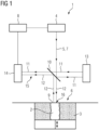
- FIG. 1 are schematic diagrams, wherein
- Fig. 1 shows an apparatus 1 for additively manufacturing three-dimensional objects 2 by means of successive layerwise selective irradiation and consolidation of layers of a build material 3 which can be consolidated by means of an energy source.
- An irradiation device 4 is provided, that is adapted to generate an energy beam 5, such as a laser beam.
- the irradiation device 4 comprises a beam guiding unit (not shown in Fig. 1 ) that is adapted to move the energy beam 5 in the build plane 6, in particular over a surface of build material 3 arranged in the build plane 6.
- the energy beam 5 is used as "writing" energy beam 5 to irradiate the build material 3, and the energy beam 5 is also used as measurement beam 7.
- the irradiation device 4 may also be deemed as measurement beam source as depicted in Fig. 1 (not part of the invention).
- the apparatus 1 further comprises a determination device 8 that is adapted to determine at least one parameter relating to the object 2 and/or a build material layer 9, for example arranged in the build plane 6 or a previously applied and irradiated layer 9 of build material 3.
- the energy beam 5 that is used as measurement beam 7 as depicted in Fig. 1 (not part of the invention), is incident on a beam splitter 10 that is adapted to split the energy beam 5 or the measurement beam 7, respectively, into a reference part 11 and a measurement part 12.
- a beam splitter 10 that is adapted to split the energy beam 5 or the measurement beam 7, respectively, into a reference part 11 and a measurement part 12.
- the energy beam 5 is used as measurement beam 7 in this exemplary embodiment.
- all details, features and advantages described with respect to the energy beam 5 are fully transferable to the measurement beam 7, as the energy beam 5 is used as measurement beam 7 or the energy beam 5 and the measurement beam 7 are identical (not part of the invention).
- the energy beam 5 is at least partially reflected at the beam splitter 10, which part of the energy beam 5 is deemed as reference part 11.
- the reference part 11 is reflected at a reference mirror 13, wherein the reflected reference part 11 is again guided towards the beam splitter 10 and passes the beam splitter 10 and is guided towards a detector unit 14.
- the part of the energy beam 5 that is incident on the beam splitter 10 and is transmitted through the beam splitter 10 is deemed as measurement part 12 and is guided onto the build plane 6, in particular onto the layer 9 of (non-consolidated) build material 3 arranged in the build plane 6.
- the measurement part 12 is (partially) reflected at the surface of build material 3 and is guided towards the beam splitter 10, wherein it is reflected towards the detector unit 14.
- the reference part 11 and the measurement part 12 that propagate from the beam splitter 10 towards the detector unit 14 can be deemed as combined part 15, wherein the beam splitter 10 can be deemed as being adapted to combine the reflected reference part 11 and the reflected measurement part 12 to guide both parts 11, 12 towards the detector unit 14.
- the detector unit 14 receives both, the reference part 11 and the measurement part 12, wherein an interference pattern is generated on the detector unit 14 (inter alia) dependent on the optical path difference of the parts 11, 12.
- the detector unit 14 may comprise at least one detector element (not shown) that can, for example, be built as or comprise at least one CCD sensor and/or at least one CMOS sensor, such as a camera.
- the interference pattern that is generated on the detector unit 14 allows for determining parameters relating to the object 2 and/or the build material layer 9. For example, variances in the interference pattern indicate that the beam path difference between the reference part 11 and the measurement part 12 occur or change, respectively. In particular, it is possible (for example via a corresponding control unit) to compensate occurring optical beam path differences due to the energy beam 5 being guided to different positions in the build plane 6. As those beam path differences may be taken into calculation and may be compensated, variances in the interference pattern relate to inequalities of the build material layer 9. In other words, if the layer 9 in the build plane 6 is even and homogenous the interference pattern on the detector unit 14 will remain constant (except influences due to the energy beam 5 being guided to different positions in the build plane 6).
- the stability of the interference pattern may be related to the stability of the additive manufacturing process, in particular the stability of a meltpool 16 that is generated via the irradiation of build material 3 with the energy beam 5 in the build plane 6.
- the meltpool 16 that is generated via the energy beam 5 can also be regarded as being stable. If changes in the interference pattern occur, an instability of the additive manufacturing process, in particular the generation of the meltpool 16, may be indicated.
- the meltpool 16 can be monitored during the additive manufacturing process.
- Fig. 2 shows an apparatus 1 for additively manufacturing three-dimensional objects 2 according to the invention.
- the setup of the apparatus 1 depicted in Fig. 2 is generally based on the setup of the apparatus 1 as depicted in Fig. 1 , the same numerals are used for the same components.
- the apparatus 1, as depicted in Fig. 2 also comprises an irradiation device 4 generating an energy beam 5, the build plane 6 in which an object 2 can be built from non-consolidated build material 3, a determination device 8, a detector unit 14, a reference mirror 13 and a beam splitter 10.
- the apparatus 1 as depicted in Fig. 2 comprises a separate measurement beam source 17.
- the energy beam 5 that is generated via the irradiation device 4 is not used as measurement beam 7 in the embodiment, as depicted in Fig. 2 .
- the measurement beam 7 is separately generated via the measurement beam source 17.
- the measurement beam 7 is guided towards the beam splitter 10, which splits the measurement beam 7 into the reference part 11 and the measurement part 12, as described before.
- the reference part 11 is transmitted through the beam splitter 10 and is reflected at the reference mirror 13 from which it is reflected and again guided towards the beam splitter 10.
- the reference part 11 is then reflected at the beam splitter 10 and guided towards the detector unit 14.
- the measurement part 12 is reflected (and thereby split of the measurement beam 7) at the beam splitter 10 and is guided towards the build plane 6.
- the measurement part 12 On its way to the build plane 6, the measurement part 12 is incident on a movement unit 28, for example a movable mirror (as indicated via arrow 18), in particular a galvanometer mirror.
- the measurement part 12 is reflected at the movement unit 28 and therefore, guided towards the build plane 6.
- the measurement part 12 that is reflected at the movement unit 28 passes through another mirror 19 and is incident in the beam guiding unit 20.
- the irradiation device 4 of the apparatus 1, as depicted in Fig. 2 is adapted to generate the energy beam 5, which is also incident on the mirror 19.
- the energy beam 5 is reflected at the mirror 19 and is therefore, also guided towards the beam guiding unit 20.
- the beam guiding unit 20 is adapted to guide the energy beam 5 and the measurement part 12 in the build plane 6, wherein it is possible that the measurement part 12 and the energy beam 5 are guided synchronously. It is also possible that dependent on a position and a movement of the movement unit 28, the measurement part 12 is moved relative to the energy beam 5, for example a preceding movement, a succeeding movement or a congruent movement or any arbitrary combination of those movements. It is also possible to define and adjust/change a distance 21 by which the measurement part 12 is positioned away from the energy beam 5.
- the measurement beam 12 incident on the build plane 6, is reflected at the build material 3 arranged in the build plane 6, in particular at the layer 9 of build material 3.
- the reflected measurement part 12 passes the beam guiding unit 20 and is transmitted through the mirror 19.
- the reflected measurement part 12 is again incident on the movement unit 28 from which it is reflected and guided through the beam splitter 10 onto the detector 14.
- the reflected reference part 11 and the reflected measurement part 12 can be deemed as combined part 15, which propagates from the beam splitter 10 to the detector unit 14.
- an irradiation pattern is generated on the detector unit 14, in particular on the detector element of the detector unit 14, based on interference of the reference part 11 and the measurement part 12 on the detector element.
- the determination device 8 is adapted to determine at least one parameter relating to the object 2 and/or a build material layer 9, as already described before.
- the measurement part 12 is moved relative to the energy beam 5 in the build plane 6. It is, for example, possible to move the measurement part 12 in advance to the energy beam 5 or following the energy beam 5. It is also possible to move the measurement part 12 in an endless loop around and/or through the position of the energy beam 5 in the build plane 6 while the energy beam 5 is moved across the build plane 6 to irradiate the build material 3 and thereby consolidate the build material 3 to form the three-dimensional object 2.
- Fig. 3 shows an exemplary path of a measurement part 12 in the build plane 6.
- the measurement part 12 is guided along an endless loop 22 that extends in the x- and y-plane, as depicted via arrows.
- the energy beam 5, in particular the spot of the energy beam 5, is guided along an energy beam path 23, wherein build material 3 arranged in the build plane 6 is irradiated thereby generating a melting track 24 behind the actual position of the energy beam 5.
- the energy beam 5 melts and thereby consolidates the build material 3 arranged in the build plane 6 as it is guided over the build plane 6.
- the measurement part 12 is moved due to a corresponding movement of the movement unit 28 in a preceding region 25 that is arranged in advance to the actual position of the energy beam 5 and the measurement part 12 is also guided into a region 26 that is congruent with the actual position of the energy beam 5 and the build plane 6 and the endless loop 22 also extends into a succeeding region 27 that follows the actual position of the energy beam 5 and the build plane 6.
- information can be generated relating to the region 25 that lies in advance to the actual position of the energy beam 5, for example information relating to a surface quality of the build material 3 arranged in the build plane 6.
- irregularities in the application quality of the build material 3 can be identified by changes in the irradiation pattern that is generated on the detector unit 14. It is also possible to monitor the region 26 that is congruent with the actual position of the energy beam 5 and the build plane 6, i.e. the region in which the meltpool 16 is generated. By guiding the measurement part 12 through the meltpool 16 information can be generated relating to a stability of the meltpool 16.
- the information or the interference pattern generated on the detector unit 14 is stable in the meltpool 16, a stable melting and consolidation process is indicated. If the interference pattern is not stable or constant on the detector unit 14, problems with the consolidation behavior can be identified.
- a succeeding region 27 can be monitored toward, as the endless loop 22 extends in a succeeding region 27 following the energy beam 5.
- the measurement part 12 may generate information about the melting track 24, such as the consolidation behavior of build material 3 that has been consolidated via irradiation with the energy beam 5.
- height information can be generated for all three regions 25 - 27, wherein for example position information can be generated about the build material 3 arranged in the build plane 6, for example relating to an object position of the object 2 relative to the powder bed.
- information can be generated about the consolidation behavior of one or multiple layers 9 of build material 3, in particular melted build material 3 along the melting track 24.
- the depicted endless loop 22 is to be understood as merely exemplary, wherein every track the measurement part 12 can be guided along can be used to monitor or the additive manufacturing process.
- the measurement part 12 may be moved synchronously and/or relative to the energy beam 5 in any arbitrary direction and/or along any arbitrary path in the x- and y-plane.
Landscapes
- Engineering & Computer Science (AREA)
- Chemical & Material Sciences (AREA)
- Materials Engineering (AREA)
- Physics & Mathematics (AREA)
- Optics & Photonics (AREA)
- Manufacturing & Machinery (AREA)
- Mechanical Engineering (AREA)
- Plasma & Fusion (AREA)
- Health & Medical Sciences (AREA)
- Toxicology (AREA)
- Ceramic Engineering (AREA)
- Analytical Chemistry (AREA)
- Automation & Control Theory (AREA)
- General Health & Medical Sciences (AREA)
- Powder Metallurgy (AREA)
- Producing Shaped Articles From Materials (AREA)
Priority Applications (5)
| Application Number | Priority Date | Filing Date | Title |
|---|---|---|---|
| EP18161072.6A EP3536485B1 (en) | 2018-03-09 | 2018-03-09 | Apparatus for additively manufacturing three-dimensional objects |
| US16/273,130 US11072113B2 (en) | 2018-03-09 | 2019-02-11 | Apparatus for additively manufacturing three-dimensional objects |
| JP2019025285A JP6817352B2 (ja) | 2018-03-09 | 2019-02-15 | 三次元物体の付加製造装置 |
| CN201910131734.6A CN110239089A (zh) | 2018-03-09 | 2019-02-22 | 用于添加式地制造三维物体的设备 |
| JP2020138300A JP2020203487A (ja) | 2018-03-09 | 2020-08-18 | 三次元物体の付加製造装置 |
Applications Claiming Priority (1)
| Application Number | Priority Date | Filing Date | Title |
|---|---|---|---|
| EP18161072.6A EP3536485B1 (en) | 2018-03-09 | 2018-03-09 | Apparatus for additively manufacturing three-dimensional objects |
Publications (2)
| Publication Number | Publication Date |
|---|---|
| EP3536485A1 EP3536485A1 (en) | 2019-09-11 |
| EP3536485B1 true EP3536485B1 (en) | 2024-06-12 |
Family
ID=61655583
Family Applications (1)
| Application Number | Title | Priority Date | Filing Date |
|---|---|---|---|
| EP18161072.6A Active EP3536485B1 (en) | 2018-03-09 | 2018-03-09 | Apparatus for additively manufacturing three-dimensional objects |
Country Status (4)
| Country | Link |
|---|---|
| US (1) | US11072113B2 (cg-RX-API-DMAC7.html) |
| EP (1) | EP3536485B1 (cg-RX-API-DMAC7.html) |
| JP (2) | JP6817352B2 (cg-RX-API-DMAC7.html) |
| CN (1) | CN110239089A (cg-RX-API-DMAC7.html) |
Families Citing this family (5)
| Publication number | Priority date | Publication date | Assignee | Title |
|---|---|---|---|---|
| EP3536485B1 (en) * | 2018-03-09 | 2024-06-12 | Concept Laser GmbH | Apparatus for additively manufacturing three-dimensional objects |
| US11987005B2 (en) | 2019-12-19 | 2024-05-21 | Concept Laser Gmbh | Build plane measurement systems and related methods |
| US12403650B2 (en) | 2022-07-15 | 2025-09-02 | General Electric Company | Additive manufacturing methods and systems |
| US12280538B2 (en) | 2022-07-15 | 2025-04-22 | General Electric Company | Additive manufacturing methods and systems with two beams traveling along opposing, wobbling paths |
| CN117109474A (zh) * | 2023-09-04 | 2023-11-24 | 武汉大学 | 一种熔池三维形貌原位实时测量装置、系统及方法 |
Family Cites Families (19)
| Publication number | Priority date | Publication date | Assignee | Title |
|---|---|---|---|---|
| DE10020559A1 (de) * | 2000-04-27 | 2001-10-31 | Hannover Laser Zentrum | Laser-Bearbeitung von Materialien |
| JP3603843B2 (ja) * | 2001-02-23 | 2004-12-22 | 日産自動車株式会社 | レーザー溶接部の品質モニタリング方法およびその装置 |
| AU2003278047A1 (en) * | 2002-10-31 | 2004-05-25 | Stephen F. Corbin | System and method for closed-loop control of laser cladding by powder injection |
| SE524421C2 (sv) * | 2002-12-19 | 2004-08-10 | Arcam Ab | Anordning samt metod för framställande av en tredimensionell produkt |
| DE102010020183B4 (de) * | 2010-05-11 | 2013-07-11 | Precitec Kg | Laserschneidkopf und Verfahren zum Schneiden eines Werkstücks mittels eines Laserschneidkopfes |
| JP2014013547A (ja) | 2012-07-05 | 2014-01-23 | Amada Co Ltd | 加工システムにおける誤差補正装置および方法 |
| DE102013208651A1 (de) * | 2013-05-10 | 2014-11-13 | Eos Gmbh Electro Optical Systems | Verfahren zum automatischen Kalibrieren einer Vorrichtung zum generativen Herstellen eines dreidimensionalen Objekts |
| DE102013008269C5 (de) * | 2013-05-15 | 2019-01-24 | Precitec Optronik Gmbh | Bearbeitungskopf für eine Laserbearbeitungsvorrichtung |
| DE102013015656B4 (de) * | 2013-09-23 | 2016-02-18 | Precitec Optronik Gmbh | Verfahren zum Messen der Eindringtiefe eines Laserstrahls in ein Werkstück, Verfahren zum Bearbeiten eines Werkstücks sowie Laserbearbeitungsvorrichtung |
| DE102013225108A1 (de) * | 2013-12-06 | 2015-06-11 | Siemens Aktiengesellschaft | Messverfahren und Bearbeitungsvorrichtung |
| JP5905060B1 (ja) | 2014-09-16 | 2016-04-20 | 株式会社東芝 | 積層造形装置および積層造形方法 |
| JP6091652B2 (ja) | 2015-03-20 | 2017-03-08 | 技術研究組合次世代3D積層造形技術総合開発機構 | 光加工ヘッド、光加工装置、その制御方法及び制御プログラム |
| DE102016005021B4 (de) * | 2016-04-22 | 2024-07-11 | Precitec Optronik Gmbh | Verfahren und Vorrichtung zur Messung der Tiefe der Dampfkapillare während eines Bearbeitungsprozesses mit einem Hochenergiestrahl |
| JP2017196026A (ja) * | 2016-04-26 | 2017-11-02 | キヤノン株式会社 | 被検体情報取得装置 |
| DE102016110266A1 (de) * | 2016-06-02 | 2017-12-07 | Fraunhofer-Gesellschaft zur Förderung der angewandten Forschung e.V. | Verfahren und Vorrichtung zur generativen Fertigung von Bauteilen |
| US20180154442A1 (en) * | 2016-12-06 | 2018-06-07 | Velo3D, Inc. | Optics, detectors, and three-dimensional printing |
| US10611092B2 (en) * | 2017-01-05 | 2020-04-07 | Velo3D, Inc. | Optics in three-dimensional printing |
| JP6826201B2 (ja) * | 2017-08-08 | 2021-02-03 | 三菱重工業株式会社 | 三次元積層造形装置の施工異常検出システム、三次元積層造形装置、三次元積層造形装置の施工異常検出方法、三次元積層造形物の製造方法、及び、三次元積層造形物 |
| EP3536485B1 (en) * | 2018-03-09 | 2024-06-12 | Concept Laser GmbH | Apparatus for additively manufacturing three-dimensional objects |
-
2018
- 2018-03-09 EP EP18161072.6A patent/EP3536485B1/en active Active
-
2019
- 2019-02-11 US US16/273,130 patent/US11072113B2/en active Active
- 2019-02-15 JP JP2019025285A patent/JP6817352B2/ja not_active Expired - Fee Related
- 2019-02-22 CN CN201910131734.6A patent/CN110239089A/zh active Pending
-
2020
- 2020-08-18 JP JP2020138300A patent/JP2020203487A/ja active Pending
Also Published As
| Publication number | Publication date |
|---|---|
| US11072113B2 (en) | 2021-07-27 |
| CN110239089A (zh) | 2019-09-17 |
| JP2019155913A (ja) | 2019-09-19 |
| JP6817352B2 (ja) | 2021-01-20 |
| EP3536485A1 (en) | 2019-09-11 |
| US20190275734A1 (en) | 2019-09-12 |
| JP2020203487A (ja) | 2020-12-24 |
Similar Documents
| Publication | Publication Date | Title |
|---|---|---|
| US11072113B2 (en) | Apparatus for additively manufacturing three-dimensional objects | |
| RU2639110C2 (ru) | Способ изготовления трехмерного изделия, устройство для изготовления трехмерного изделия и способ изготовления такого устройства | |
| CN107107481B (zh) | 用于生成地制造三维结构件的设备 | |
| EP3597406B1 (en) | Apparatus for additively manufacturing three-dimensional objects | |
| US20200023583A1 (en) | Apparatus for additively manufacturing three-dimensional objects | |
| EP3524410B1 (en) | Apparatus for additively manufacturing three-dimensional objects | |
| US20200223139A1 (en) | Method for operating an apparatus for additively manufacturing three-dimensional objects | |
| EP3597401B1 (en) | Apparatus for additively manufacturing of three-dimensional objects | |
| US10882135B2 (en) | Apparatus for additively manufacturing of three-dimensional objects | |
| CN110435141B (zh) | 添加式地制造三维物体的装置 | |
| US11904545B2 (en) | Apparatus for additively manufacturing three-dimensional objects | |
| EP3613561B1 (en) | Apparatus for additively manufacturing three-dimensional objects | |
| JP2021066960A (ja) | 3次元の物体を付加製造する装置 | |
| US20190176399A1 (en) | Apparatus for additively manufacturing of three-dimensional objects | |
| WO2020016726A1 (en) | Method for operating an apparatus for additively manufacturing three-dimensional objects |
Legal Events
| Date | Code | Title | Description |
|---|---|---|---|
| PUAI | Public reference made under article 153(3) epc to a published international application that has entered the european phase |
Free format text: ORIGINAL CODE: 0009012 |
|
| STAA | Information on the status of an ep patent application or granted ep patent |
Free format text: STATUS: REQUEST FOR EXAMINATION WAS MADE |
|
| STAA | Information on the status of an ep patent application or granted ep patent |
Free format text: STATUS: EXAMINATION IS IN PROGRESS |
|
| 17P | Request for examination filed |
Effective date: 20190121 |
|
| AK | Designated contracting states |
Kind code of ref document: A1 Designated state(s): AL AT BE BG CH CY CZ DE DK EE ES FI FR GB GR HR HU IE IS IT LI LT LU LV MC MK MT NL NO PL PT RO RS SE SI SK SM TR |
|
| AX | Request for extension of the european patent |
Extension state: BA ME |
|
| 17Q | First examination report despatched |
Effective date: 20190820 |
|
| RAP1 | Party data changed (applicant data changed or rights of an application transferred) |
Owner name: CONCEPT LASER GMBH |
|
| REG | Reference to a national code |
Ref legal event code: R079 Ipc: B29C0064135000 Ref country code: DE Ref legal event code: R079 Ref document number: 602018070457 Country of ref document: DE Free format text: PREVIOUS MAIN CLASS: B29C0064393000 Ipc: B29C0064135000 |
|
| RIC1 | Information provided on ipc code assigned before grant |
Ipc: B33Y 50/02 20150101ALN20231020BHEP Ipc: B33Y 30/00 20150101ALN20231020BHEP Ipc: B33Y 10/00 20150101ALN20231020BHEP Ipc: B22F 12/00 20210101ALN20231020BHEP Ipc: B22F 10/28 20210101ALN20231020BHEP Ipc: B29C 64/00 20170101ALI20231020BHEP Ipc: B29C 64/393 20170101ALI20231020BHEP Ipc: B29C 64/268 20170101ALI20231020BHEP Ipc: B29C 64/153 20170101ALI20231020BHEP Ipc: B29C 64/135 20170101AFI20231020BHEP |
|
| GRAP | Despatch of communication of intention to grant a patent |
Free format text: ORIGINAL CODE: EPIDOSNIGR1 |
|
| STAA | Information on the status of an ep patent application or granted ep patent |
Free format text: STATUS: GRANT OF PATENT IS INTENDED |
|
| RIC1 | Information provided on ipc code assigned before grant |
Ipc: B33Y 10/00 20150101ALN20240108BHEP Ipc: B22F 12/33 20210101ALN20240108BHEP Ipc: B22F 10/37 20210101ALN20240108BHEP Ipc: B22F 10/28 20210101ALN20240108BHEP Ipc: B23K 26/03 20060101ALI20240108BHEP Ipc: B33Y 50/02 20150101ALI20240108BHEP Ipc: B33Y 30/00 20150101ALI20240108BHEP Ipc: B22F 12/90 20210101ALI20240108BHEP Ipc: B22F 12/49 20210101ALI20240108BHEP Ipc: B29C 64/00 20170101ALI20240108BHEP Ipc: B29C 64/393 20170101ALI20240108BHEP Ipc: B29C 64/268 20170101ALI20240108BHEP Ipc: B29C 64/153 20170101ALI20240108BHEP Ipc: B29C 64/135 20170101AFI20240108BHEP |
|
| RIC1 | Information provided on ipc code assigned before grant |
Ipc: B33Y 10/00 20150101ALN20240120BHEP Ipc: B22F 12/33 20210101ALN20240120BHEP Ipc: B22F 10/37 20210101ALN20240120BHEP Ipc: B22F 10/28 20210101ALN20240120BHEP Ipc: B23K 26/03 20060101ALI20240120BHEP Ipc: B33Y 50/02 20150101ALI20240120BHEP Ipc: B33Y 30/00 20150101ALI20240120BHEP Ipc: B22F 12/90 20210101ALI20240120BHEP Ipc: B22F 12/49 20210101ALI20240120BHEP Ipc: B29C 64/00 20170101ALI20240120BHEP Ipc: B29C 64/393 20170101ALI20240120BHEP Ipc: B29C 64/268 20170101ALI20240120BHEP Ipc: B29C 64/153 20170101ALI20240120BHEP Ipc: B29C 64/135 20170101AFI20240120BHEP |
|
| INTG | Intention to grant announced |
Effective date: 20240205 |
|
| GRAS | Grant fee paid |
Free format text: ORIGINAL CODE: EPIDOSNIGR3 |
|
| GRAA | (expected) grant |
Free format text: ORIGINAL CODE: 0009210 |
|
| STAA | Information on the status of an ep patent application or granted ep patent |
Free format text: STATUS: THE PATENT HAS BEEN GRANTED |
|
| AK | Designated contracting states |
Kind code of ref document: B1 Designated state(s): AL AT BE BG CH CY CZ DE DK EE ES FI FR GB GR HR HU IE IS IT LI LT LU LV MC MK MT NL NO PL PT RO RS SE SI SK SM TR |
|
| P01 | Opt-out of the competence of the unified patent court (upc) registered |
Effective date: 20240507 |
|
| REG | Reference to a national code |
Ref country code: GB Ref legal event code: FG4D |
|
| REG | Reference to a national code |
Ref country code: CH Ref legal event code: EP |
|
| REG | Reference to a national code |
Ref country code: IE Ref legal event code: FG4D |
|
| REG | Reference to a national code |
Ref country code: DE Ref legal event code: R096 Ref document number: 602018070457 Country of ref document: DE |
|
| PG25 | Lapsed in a contracting state [announced via postgrant information from national office to epo] |
Ref country code: BG Free format text: LAPSE BECAUSE OF FAILURE TO SUBMIT A TRANSLATION OF THE DESCRIPTION OR TO PAY THE FEE WITHIN THE PRESCRIBED TIME-LIMIT Effective date: 20240612 |
|
| PG25 | Lapsed in a contracting state [announced via postgrant information from national office to epo] |
Ref country code: HR Free format text: LAPSE BECAUSE OF FAILURE TO SUBMIT A TRANSLATION OF THE DESCRIPTION OR TO PAY THE FEE WITHIN THE PRESCRIBED TIME-LIMIT Effective date: 20240612 Ref country code: FI Free format text: LAPSE BECAUSE OF FAILURE TO SUBMIT A TRANSLATION OF THE DESCRIPTION OR TO PAY THE FEE WITHIN THE PRESCRIBED TIME-LIMIT Effective date: 20240612 |
|
| REG | Reference to a national code |
Ref country code: LT Ref legal event code: MG9D |
|
| PG25 | Lapsed in a contracting state [announced via postgrant information from national office to epo] |
Ref country code: GR Free format text: LAPSE BECAUSE OF FAILURE TO SUBMIT A TRANSLATION OF THE DESCRIPTION OR TO PAY THE FEE WITHIN THE PRESCRIBED TIME-LIMIT Effective date: 20240913 |
|
| REG | Reference to a national code |
Ref country code: NL Ref legal event code: MP Effective date: 20240612 |
|
| PG25 | Lapsed in a contracting state [announced via postgrant information from national office to epo] |
Ref country code: ES Free format text: LAPSE BECAUSE OF FAILURE TO SUBMIT A TRANSLATION OF THE DESCRIPTION OR TO PAY THE FEE WITHIN THE PRESCRIBED TIME-LIMIT Effective date: 20240612 |
|
| PG25 | Lapsed in a contracting state [announced via postgrant information from national office to epo] |
Ref country code: LV Free format text: LAPSE BECAUSE OF FAILURE TO SUBMIT A TRANSLATION OF THE DESCRIPTION OR TO PAY THE FEE WITHIN THE PRESCRIBED TIME-LIMIT Effective date: 20240612 |
|
| PG25 | Lapsed in a contracting state [announced via postgrant information from national office to epo] |
Ref country code: NO Free format text: LAPSE BECAUSE OF FAILURE TO SUBMIT A TRANSLATION OF THE DESCRIPTION OR TO PAY THE FEE WITHIN THE PRESCRIBED TIME-LIMIT Effective date: 20240912 Ref country code: LV Free format text: LAPSE BECAUSE OF FAILURE TO SUBMIT A TRANSLATION OF THE DESCRIPTION OR TO PAY THE FEE WITHIN THE PRESCRIBED TIME-LIMIT Effective date: 20240612 Ref country code: HR Free format text: LAPSE BECAUSE OF FAILURE TO SUBMIT A TRANSLATION OF THE DESCRIPTION OR TO PAY THE FEE WITHIN THE PRESCRIBED TIME-LIMIT Effective date: 20240612 Ref country code: GR Free format text: LAPSE BECAUSE OF FAILURE TO SUBMIT A TRANSLATION OF THE DESCRIPTION OR TO PAY THE FEE WITHIN THE PRESCRIBED TIME-LIMIT Effective date: 20240913 Ref country code: FI Free format text: LAPSE BECAUSE OF FAILURE TO SUBMIT A TRANSLATION OF THE DESCRIPTION OR TO PAY THE FEE WITHIN THE PRESCRIBED TIME-LIMIT Effective date: 20240612 Ref country code: ES Free format text: LAPSE BECAUSE OF FAILURE TO SUBMIT A TRANSLATION OF THE DESCRIPTION OR TO PAY THE FEE WITHIN THE PRESCRIBED TIME-LIMIT Effective date: 20240612 Ref country code: BG Free format text: LAPSE BECAUSE OF FAILURE TO SUBMIT A TRANSLATION OF THE DESCRIPTION OR TO PAY THE FEE WITHIN THE PRESCRIBED TIME-LIMIT Effective date: 20240612 Ref country code: RS Free format text: LAPSE BECAUSE OF FAILURE TO SUBMIT A TRANSLATION OF THE DESCRIPTION OR TO PAY THE FEE WITHIN THE PRESCRIBED TIME-LIMIT Effective date: 20240912 |
|
| PG25 | Lapsed in a contracting state [announced via postgrant information from national office to epo] |
Ref country code: NL Free format text: LAPSE BECAUSE OF FAILURE TO SUBMIT A TRANSLATION OF THE DESCRIPTION OR TO PAY THE FEE WITHIN THE PRESCRIBED TIME-LIMIT Effective date: 20240612 |
|
| REG | Reference to a national code |
Ref country code: AT Ref legal event code: MK05 Ref document number: 1693875 Country of ref document: AT Kind code of ref document: T Effective date: 20240612 |
|
| PG25 | Lapsed in a contracting state [announced via postgrant information from national office to epo] |
Ref country code: NL Free format text: LAPSE BECAUSE OF FAILURE TO SUBMIT A TRANSLATION OF THE DESCRIPTION OR TO PAY THE FEE WITHIN THE PRESCRIBED TIME-LIMIT Effective date: 20240612 |
|
| PG25 | Lapsed in a contracting state [announced via postgrant information from national office to epo] |
Ref country code: PT Free format text: LAPSE BECAUSE OF FAILURE TO SUBMIT A TRANSLATION OF THE DESCRIPTION OR TO PAY THE FEE WITHIN THE PRESCRIBED TIME-LIMIT Effective date: 20241014 |
|
| PG25 | Lapsed in a contracting state [announced via postgrant information from national office to epo] |
Ref country code: PT Free format text: LAPSE BECAUSE OF FAILURE TO SUBMIT A TRANSLATION OF THE DESCRIPTION OR TO PAY THE FEE WITHIN THE PRESCRIBED TIME-LIMIT Effective date: 20241014 |
|
| PG25 | Lapsed in a contracting state [announced via postgrant information from national office to epo] |
Ref country code: PL Free format text: LAPSE BECAUSE OF FAILURE TO SUBMIT A TRANSLATION OF THE DESCRIPTION OR TO PAY THE FEE WITHIN THE PRESCRIBED TIME-LIMIT Effective date: 20240612 |
|
| PG25 | Lapsed in a contracting state [announced via postgrant information from national office to epo] |
Ref country code: EE Free format text: LAPSE BECAUSE OF FAILURE TO SUBMIT A TRANSLATION OF THE DESCRIPTION OR TO PAY THE FEE WITHIN THE PRESCRIBED TIME-LIMIT Effective date: 20240612 |
|
| PG25 | Lapsed in a contracting state [announced via postgrant information from national office to epo] |
Ref country code: IS Free format text: LAPSE BECAUSE OF FAILURE TO SUBMIT A TRANSLATION OF THE DESCRIPTION OR TO PAY THE FEE WITHIN THE PRESCRIBED TIME-LIMIT Effective date: 20241012 Ref country code: AT Free format text: LAPSE BECAUSE OF FAILURE TO SUBMIT A TRANSLATION OF THE DESCRIPTION OR TO PAY THE FEE WITHIN THE PRESCRIBED TIME-LIMIT Effective date: 20240612 |
|
| PG25 | Lapsed in a contracting state [announced via postgrant information from national office to epo] |
Ref country code: CZ Free format text: LAPSE BECAUSE OF FAILURE TO SUBMIT A TRANSLATION OF THE DESCRIPTION OR TO PAY THE FEE WITHIN THE PRESCRIBED TIME-LIMIT Effective date: 20240612 |
|
| PG25 | Lapsed in a contracting state [announced via postgrant information from national office to epo] |
Ref country code: SK Free format text: LAPSE BECAUSE OF FAILURE TO SUBMIT A TRANSLATION OF THE DESCRIPTION OR TO PAY THE FEE WITHIN THE PRESCRIBED TIME-LIMIT Effective date: 20240612 Ref country code: RO Free format text: LAPSE BECAUSE OF FAILURE TO SUBMIT A TRANSLATION OF THE DESCRIPTION OR TO PAY THE FEE WITHIN THE PRESCRIBED TIME-LIMIT Effective date: 20240612 |
|
| PG25 | Lapsed in a contracting state [announced via postgrant information from national office to epo] |
Ref country code: SM Free format text: LAPSE BECAUSE OF FAILURE TO SUBMIT A TRANSLATION OF THE DESCRIPTION OR TO PAY THE FEE WITHIN THE PRESCRIBED TIME-LIMIT Effective date: 20240612 |
|
| PG25 | Lapsed in a contracting state [announced via postgrant information from national office to epo] |
Ref country code: SM Free format text: LAPSE BECAUSE OF FAILURE TO SUBMIT A TRANSLATION OF THE DESCRIPTION OR TO PAY THE FEE WITHIN THE PRESCRIBED TIME-LIMIT Effective date: 20240612 Ref country code: SK Free format text: LAPSE BECAUSE OF FAILURE TO SUBMIT A TRANSLATION OF THE DESCRIPTION OR TO PAY THE FEE WITHIN THE PRESCRIBED TIME-LIMIT Effective date: 20240612 Ref country code: RO Free format text: LAPSE BECAUSE OF FAILURE TO SUBMIT A TRANSLATION OF THE DESCRIPTION OR TO PAY THE FEE WITHIN THE PRESCRIBED TIME-LIMIT Effective date: 20240612 Ref country code: PL Free format text: LAPSE BECAUSE OF FAILURE TO SUBMIT A TRANSLATION OF THE DESCRIPTION OR TO PAY THE FEE WITHIN THE PRESCRIBED TIME-LIMIT Effective date: 20240612 Ref country code: IS Free format text: LAPSE BECAUSE OF FAILURE TO SUBMIT A TRANSLATION OF THE DESCRIPTION OR TO PAY THE FEE WITHIN THE PRESCRIBED TIME-LIMIT Effective date: 20241012 Ref country code: EE Free format text: LAPSE BECAUSE OF FAILURE TO SUBMIT A TRANSLATION OF THE DESCRIPTION OR TO PAY THE FEE WITHIN THE PRESCRIBED TIME-LIMIT Effective date: 20240612 Ref country code: CZ Free format text: LAPSE BECAUSE OF FAILURE TO SUBMIT A TRANSLATION OF THE DESCRIPTION OR TO PAY THE FEE WITHIN THE PRESCRIBED TIME-LIMIT Effective date: 20240612 Ref country code: AT Free format text: LAPSE BECAUSE OF FAILURE TO SUBMIT A TRANSLATION OF THE DESCRIPTION OR TO PAY THE FEE WITHIN THE PRESCRIBED TIME-LIMIT Effective date: 20240612 |
|
| PG25 | Lapsed in a contracting state [announced via postgrant information from national office to epo] |
Ref country code: IT Free format text: LAPSE BECAUSE OF FAILURE TO SUBMIT A TRANSLATION OF THE DESCRIPTION OR TO PAY THE FEE WITHIN THE PRESCRIBED TIME-LIMIT Effective date: 20240612 |
|
| REG | Reference to a national code |
Ref country code: DE Ref legal event code: R097 Ref document number: 602018070457 Country of ref document: DE |
|
| PG25 | Lapsed in a contracting state [announced via postgrant information from national office to epo] |
Ref country code: DK Free format text: LAPSE BECAUSE OF FAILURE TO SUBMIT A TRANSLATION OF THE DESCRIPTION OR TO PAY THE FEE WITHIN THE PRESCRIBED TIME-LIMIT Effective date: 20240612 |
|
| PLBE | No opposition filed within time limit |
Free format text: ORIGINAL CODE: 0009261 |
|
| STAA | Information on the status of an ep patent application or granted ep patent |
Free format text: STATUS: NO OPPOSITION FILED WITHIN TIME LIMIT |
|
| 26N | No opposition filed |
Effective date: 20250313 |
|
| PG25 | Lapsed in a contracting state [announced via postgrant information from national office to epo] |
Ref country code: SE Free format text: LAPSE BECAUSE OF FAILURE TO SUBMIT A TRANSLATION OF THE DESCRIPTION OR TO PAY THE FEE WITHIN THE PRESCRIBED TIME-LIMIT Effective date: 20240612 |
|
| PG25 | Lapsed in a contracting state [announced via postgrant information from national office to epo] |
Ref country code: MC Free format text: LAPSE BECAUSE OF FAILURE TO SUBMIT A TRANSLATION OF THE DESCRIPTION OR TO PAY THE FEE WITHIN THE PRESCRIBED TIME-LIMIT Effective date: 20240612 |
|
| REG | Reference to a national code |
Ref country code: CH Ref legal event code: H13 Free format text: ST27 STATUS EVENT CODE: U-0-0-H10-H13 (AS PROVIDED BY THE NATIONAL OFFICE) Effective date: 20251023 |
|
| PG25 | Lapsed in a contracting state [announced via postgrant information from national office to epo] |
Ref country code: LU Free format text: LAPSE BECAUSE OF NON-PAYMENT OF DUE FEES Effective date: 20250309 |
|
| GBPC | Gb: european patent ceased through non-payment of renewal fee |
Effective date: 20250309 |
|
| REG | Reference to a national code |
Ref country code: BE Ref legal event code: MM Effective date: 20250331 |
|
| PG25 | Lapsed in a contracting state [announced via postgrant information from national office to epo] |
Ref country code: GB Free format text: LAPSE BECAUSE OF NON-PAYMENT OF DUE FEES Effective date: 20250309 |
|
| PG25 | Lapsed in a contracting state [announced via postgrant information from national office to epo] |
Ref country code: FR Free format text: LAPSE BECAUSE OF NON-PAYMENT OF DUE FEES Effective date: 20250331 |
|
| PG25 | Lapsed in a contracting state [announced via postgrant information from national office to epo] |
Ref country code: BE Free format text: LAPSE BECAUSE OF NON-PAYMENT OF DUE FEES Effective date: 20250331 |
|
| PG25 | Lapsed in a contracting state [announced via postgrant information from national office to epo] |
Ref country code: CH Free format text: LAPSE BECAUSE OF NON-PAYMENT OF DUE FEES Effective date: 20250331 |
|
| PG25 | Lapsed in a contracting state [announced via postgrant information from national office to epo] |
Ref country code: IE Free format text: LAPSE BECAUSE OF NON-PAYMENT OF DUE FEES Effective date: 20250309 |
|
| PGFP | Annual fee paid to national office [announced via postgrant information from national office to epo] |
Ref country code: DE Payment date: 20260219 Year of fee payment: 9 |