EP3536404A1 - Stützvorrichtung für getriebepaar und industrieapplikation - Google Patents
Stützvorrichtung für getriebepaar und industrieapplikation Download PDFInfo
- Publication number
- EP3536404A1 EP3536404A1 EP18160708.6A EP18160708A EP3536404A1 EP 3536404 A1 EP3536404 A1 EP 3536404A1 EP 18160708 A EP18160708 A EP 18160708A EP 3536404 A1 EP3536404 A1 EP 3536404A1
- Authority
- EP
- European Patent Office
- Prior art keywords
- support
- flange
- support device
- gear
- support flange
- Prior art date
- Legal status (The legal status is an assumption and is not a legal conclusion. Google has not performed a legal analysis and makes no representation as to the accuracy of the status listed.)
- Granted
Links
Images


Classifications
-
- B—PERFORMING OPERATIONS; TRANSPORTING
- B02—CRUSHING, PULVERISING, OR DISINTEGRATING; PREPARATORY TREATMENT OF GRAIN FOR MILLING
- B02C—CRUSHING, PULVERISING, OR DISINTEGRATING IN GENERAL; MILLING GRAIN
- B02C4/00—Crushing or disintegrating by roller mills
- B02C4/28—Details
- B02C4/42—Driving mechanisms; Roller speed control
- B02C4/426—Torque counterbalancing mechanisms
-
- F—MECHANICAL ENGINEERING; LIGHTING; HEATING; WEAPONS; BLASTING
- F16—ENGINEERING ELEMENTS AND UNITS; GENERAL MEASURES FOR PRODUCING AND MAINTAINING EFFECTIVE FUNCTIONING OF MACHINES OR INSTALLATIONS; THERMAL INSULATION IN GENERAL
- F16H—GEARING
- F16H57/00—General details of gearing
- F16H57/02—Gearboxes; Mounting gearing therein
- F16H57/021—Shaft support structures, e.g. partition walls, bearing eyes, casing walls or covers with bearings
-
- F—MECHANICAL ENGINEERING; LIGHTING; HEATING; WEAPONS; BLASTING
- F16—ENGINEERING ELEMENTS AND UNITS; GENERAL MEASURES FOR PRODUCING AND MAINTAINING EFFECTIVE FUNCTIONING OF MACHINES OR INSTALLATIONS; THERMAL INSULATION IN GENERAL
- F16H—GEARING
- F16H57/00—General details of gearing
- F16H57/08—General details of gearing of gearings with members having orbital motion
Definitions
- the invention relates to a support device for transmission pair, wherein the transmission are mounted side by side.
- the invention also relates to an industrial application equipped with a corresponding support device.
- Out EP 0 775 525 A1 is a torque support for plugged gear known to be driven by the counter-rotating rollers.
- the torque support comprises two torque arms, each connected to a gearbox. Each torque support substantially engages the adjacent gear and has an end to which a coupling rod is attached. Each of the coupling rods in turn is connected to a short torque arm, which is attached to the respective adjacent transmission. As a result, reaction torques are introduced via the connecting rods as supporting forces in the respective adjacent transmission.
- a supporting device which is suitable for fastening a gear pair, that is, a first and a second gear.
- the support device comprises for this purpose two gear supports, which are arranged adjacent to each other.
- Each of the gear supports has a support flange, ie a first and second support flange. It is on the first support flange a first support attached.
- the first support is designed to introduce a first support force into the second support flange.
- the first supporting force is caused for example by a reaction torque, which is again caused by a driving torque, which is introduced into the first transmission.
- the second support is designed to initiate a second support force in the first support flange.
- the support forces can each be designed as tensile or compressive forces.
- the support forces are thereby introduced radially, tangentially and / or a combination thereof in the respective support flange.
- This overall advantageous storage of the first and second transmission is achieved during normal operation.
- the second support is designed such that the first support extends through the second support. This allows a close spatial arrangement of the two supports and allows a favorable and low-deformation attachment of the supports to their respective support flanges. As a result, higher support forces can be introduced into the support flanges with constant mass of the support arms.
- the support device according to the invention can be produced and inspected in a simple manner, and thus cost-efficient.
- the support device according to the invention is used for transmissions which are designed to transmit powers of 100 kW to 10 MW, in particular 200 kW to 7.0 MW.
- the support device according to the invention can also be connected to drive means such as electric motors or hydraulic motors instead of gears.
- the first support is einlaschig formed and the second support saulaschig.
- Einlaschig here is to understand that the first support at least partially comprises only a substantially flat component and in this section mechanical as a disc is writable.
- two-lobe is to be understood as meaning that the second support comprises, at least in sections, only two substantially parallel arranged planar components which in turn can be written in the corresponding sections as write.
- the second support on a clear space, which is adapted to at least partially accommodate the single-laced first support.
- a combination of a single-laced first post and a two-lobe second post readily allows the first post to extend through the second post.
- Corresponding supports can be produced quickly and cost-efficiently in a simple manner. Furthermore, single-lobes and two-lobes supports may be formed with recesses which allow weight savings in the supports, thus simplifying the assembly of the claimed support device. In addition, according to einlaschige and two-lobed supports in a simple manner mechanically calculable, which allows rapid adaptation of the claimed solution to different applications.
- first and second support in the claimed support device can also be arranged in two sections separated from each other.
- a two-part separation means that two cutting planes are required to cut the first support away from the second support in terms of engineering mechanics. As a result, a simple construction is guaranteed overall.
- the first support may comprise a support arm formed in a flange main plane of the first support flange.
- a flange main plane is a plane that is substantially perpendicular to at least one major axis of a transmission mounted on the support device.
- the main axis is, for example, the axis around which a Gear input shaft and / or transmission output shaft rotates in a normal operation.
- the support arm on the first support is adapted to engage over the second transmission support, and thus the second support flange.
- the support arm on the first support flange is thus designed to initiate a support force laterally outward into the second support flange.
- the first support flange is thus claimed in a normal operation by the support arm so that at most negligible extent to bending.
- One aspect of the proposed solution consists in recognizing that a bending stress of support flanges substantially determines the mechanical strength of support flanges, and thus of corresponding support devices.
- a first support the support arm of which extends substantially in a flange main plane, provides an increase in mechanical strength of the support device, and thus an opportunity for increased performance of a connected mechanical application.
- the increased strength increases the life and reliability of the first support flange.
- bending stresses are reduced by releasable fasteners and acting on these axial and radial forces with which the first support is attached to the first flange support.
- screws can be used as a releasable fastening means in the claimed support device.
- the use of expensive releasable fastening means, such as fitting screws, is thus not consistently required or preferably unnecessary.
- Such elaborate fasteners can be replaced in the claimed solution by screws or pins with reduced sizes, lower grades, such as strength classes.
- the support arm may be substantially symmetrical in the flange main plane be educated. Such a design of the support arm is also referred to as a riding arrangement.
- the second support may have two support arms, which are formed on mutually remote end faces of the second support flange.
- the clear space between the support arms of the second support is thus divided substantially symmetrically by a flange main plane of the second support flange.
- the support device can also be equipped on the first and / or second support arm at its end with a strut.
- the strut which is attached to the end of the support arm of the first support, is also coupled to the second support flange.
- the strut which is attached to the end of the support arm of the second support, is also coupled to the first support flange.
- the struts can each be coupled with an eyebrow connection to the corresponding support arm and so transmit a support force to the first and second support flange.
- the strut is designed to transmit a tensile force and / or compressive force, so that different load conditions, ie directions of rotation of transmission input shafts, can be accommodated by the support device.
- the struts may each be formed to a substantially bending moment-free introduction of a tensile force or compressive force in the first and second support flange.
- the struts are each connected to the first and second support and the first and second support flange in such a way that the transmitted tensile force or compressive force in the first and second flange main plane is located.
- the tensile force or compressive force can be introduced freely from an axial component in the first and second support flange.
- the tensile force or compressive force based on the main axis of the respective transmission, as a combination of a radial force and a tangential force can be displayed.
- a corresponding strut anchorage may be attached to the first and / or second support flange.
- the strut anchor at the first and / or second support flange may be attached to the first and second support, respectively.
- the strut anchorage can in particular be formed integrally with the first or second support, so be molded.
- the production of the first and / or second support flange is simplified.
- the first and / or second support flange may thus be substantially rotationally symmetrical with respect to the main axis of the associated transmission.
- the number of components is reduced, in particular, separate fasteners for the strut anchors saved, which in turn ensures a simplified assembly.
- the combination of support flange and strut anchorage allows constructive adaptation of a transition between the strut anchor and the associated support arm. Consequently, the transition from the strut anchorage to the support arm can be specifically constructed in terms of load and material, and increased material utilization can be achieved.
- At least one of the strut anchorages can be formed directly on the first and second support flange.
- An integrally formed on the first or second support flange strut anchorage provides an easy way to load and initiated material initiated by a strut supporting force in the first or second support flange. Furthermore, by a molded strut anchorage Saved against separate strut anchors in differential construction fastening means and assembly costs.
- first and / or second support flange may be formed radially shortened at least in sections in the region of the respective flange main plane.
- a radial shortening may be formed as a deviation from a rotationally symmetrical basic shape of the first and / or second support flange. This may in particular be a cut flange contour.
- the radially shortened first and / or second support flange serves to reduce a main axis distance between the main axes of the transmission.
- the support flanges may be arranged opposite one another such that the flange main planes of the two support flanges are substantially identical. Due to the radial shortening of the support flanges so a more compact positioning of the transmission is possible.
- the claimed solution is therefore also useful in mechanical applications that require a close main axis distance.
- the claimed support device has an increased range of use.
- existing mechanical applications which are defined by a maximum available space for installation by a main axis spacing
- a more powerful drive and / or transmission can be used by the claimed solution.
- Existing industrial applications are thus easily removable by the claimed support device and an increased power density can be achieved.
- first and / or second support flange may be formed as a housing component of a transmission.
- the first and / or second support flange may in particular be designed as a drive-side housing section, in which extends an output shaft of the corresponding gear. This achieves a high degree of integration in the construction of an industrial application equipped with a corresponding support device.
- the underlying task is also solved by an industrial application according to the invention.
- the industrial application has a first transmission to which drive power can be supplied via a first transmission input shaft, that is to say a drive torque at an operating speed.
- the industrial application also includes a second transmission, to which drive power can be supplied via a second transmission input shaft, essentially analogously to the first transmission.
- the first and second transmission input shafts have opposite directions of rotation in intended operation, which causes corresponding reaction torques.
- the first and second gears are attached to a support device in which the reaction forces are caused by the drive powers and in which a load condition is set depending on the present drive powers.
- the support device is designed according to one of the embodiments described above. The corresponding support device simplifies the assembly of the industrial application.
- the industrial application can be designed for example as a mill, roller mill, cement mill, sugar mill, extruder, conveyor, rock crusher, roll crusher, roller press, roller press, pump, fan, marine propulsion or lifting device.
- first and / or second transmission may be formed as a planetary gear.
- Planetary gears offer a high power density and make it possible to take advantage of the increased mechanical strength of the support device in particular degree. As a result, the advantages of the claimed support device are achieved overall to a high degree.
- each of the gears can also be used as spur gears, be designed as a worm gear, or as a bevel gear.
- FIG. 1 schematically shows a first embodiment of a support device 10 according to the invention, which has a first and second gear holder 12, 14, each of which is adapted to attach thereto a not-shown gear 40.
- the first gear holder 12 has a first support flange 16 and the second gear holder 14 has a second support flange 18.
- torques 25 are introduced into the gear 40, which rotate about their main axes 15.
- the main axes 15 have a major axis spacing 46 to each other.
- the torques 25 have opposite directions of rotation 27.
- reaction torques 30 each have directions of reaction 31, which are opposite to the corresponding introduced torques 25 of the transmission 40 on the respective transmission holder 12, 14.
- the first and second support flange 16, 18 are thus oppositely oriented reaction torques 30 subjected.
- a first support 22 is attached via a plurality of fastening means 33, which are received in corresponding recesses 32, so that the reaction torque 30, which acts on the first support flange 16, also acts on the first support 16.
- the first support 22 has a support arm 26 which engages over the adjacently arranged second support flange 18 substantially.
- the support arm 26 of the first support 22 is arranged substantially in a flange main plane 20 of the first support flange 16.
- the flange main plane 20 is to be understood as meaning the plane which is defined by the recesses 32 for the fastening means 33 and is substantially perpendicular to a corresponding main axis 15 of a gear 40.
- the arrangement of the support arm 26 of the first support 22 in the flange main plane 20 of the first support flange 16 is also referred to as a riding arrangement.
- the first support 22 is pivotally connected to a strut 34 via an eye bar connection 36.
- the strut 34 at the corresponding support arm end 28 in turn is connected via a further eye bar connection 36 with a mounting bearing 23, which in turn is formed integrally with the second support 24.
- the second support 24 is connected via fasteners 33 to the second support flange 18.
- a reaction torque 30, which results from the torque 25 of a transmission 40 on the first transmission holder 12, is introduced via the support arm 26 of the first support 22 in the second support flange 18.
- a tensile force 35 is exerted by the mounting bearing 23 on the second support flange 18 on the corresponding strut 34.
- a reaction torque 30, which occurs as a result of a torque 25 of a transmission 40, that on the second transmission support 14 is mounted, introduced via the second support 24 in the first support flange 16.
- the first support 22 has only one support arm 26 and is thus formed einlaschig.
- the second support 24 has two support arms 26, which are formed substantially congruent and spaced from one another on the second support flange 18 are mounted. Thus, the second support 24 is formed two-lobe.
- the support arms 26 of the second support 24 are spaced apart such that the support arm 26 of the first support 22 extends through a clearance 29 between the support arms 26 of the second support 24.
- the first support 22 extends through the second support 24.
- the support arm 26 of the first support 22 and the support arms 26 of the second support 26 are thus separated from each other in two sections. Further, each of the support arms 26 is provided in the support 10 with recesses 21, through which an improved material utilization of the support arms 26 is achieved.
- the arrangement of the support arms 26 of the first and second supports 24 allows substantially pure coplanar forces and torques to be present in the flange main planes 20 of the first and second support flanges 16, 18, and thus the first and second support flanges 16, 18 are substantially free of bending moment ,
- This aspect is in FIG. 2 shown in more detail.
- the first and second support flange 16, 18 on sections facing each other in the region of the Flanschhauptebenen 20 partially formed radially shortened. As a result, the major axis spacing 46 is reduced over the solutions known in the art.
- FIG. 2 is a schematic detail view of the embodiment according to FIG. 1 represented in the region of the first transmission holder 12.
- the first support 22 is fastened via at least one fastening means 33 to the first support flange 16, which has corresponding recesses 32 for receiving the fastening elements 33.
- the at least one fastening means 33 is designed as a screw with nut.
- the support arm 26 is formed and on the first support flange 16, the flange main plane 20 of the first support flange 16 divides the support arm 26 of the first support 22 substantially symmetrically. In this case, the support arm 26 is formed einlaschig. On the support arm 26, a bending force 38, which results from the tensile force 35, according to FIG.
- FIG. 3 a detailed view of the embodiment of FIG. 1 displayed.
- FIG. 3 shows a longitudinal section in the region of the second support flange 18 on the second gear holder 14.
- a second support 24 is attached via fastening means 33, which are formed as screws with nuts.
- the fastening means 33 are received in recesses 32 in the second support 22 and the second support flange 18.
- the second support 18 has two support arms 26, which are substantially parallel to each other. Between the support arms 26, a clear space 29 is formed, which is adapted to a support arm 26 of a first support 22 as in FIG. 2 take. As a result, it is possible that the first support 22 according to FIG. 2 extends through the second support 24.
- the support arms 26 of the second support 24 are symmetrical to one Flange main plane 20 which extends substantially centrally through the second support flange 18.
- On each of the support arms 26 according to FIG. 3 acts a bending force 38, which is caused by a tensile force 35, which occurs in normal operation by a tensile force 35 at least one support arm end 28.
- the bending forces 38 act substantially parallel to the flange main plane 20, so that bending moments 42, which are suitable for causing a deflection 44 of the support arms 26 along the main axis of rotation 15, become zero.
- the reduction of the material stress thus achieved ensures an increased service life of the second support 18.
- the torque 25 which is transmitted via a transmission 40 which is attached to the second transmission support 14 can also be increased, and so for the second support 24 and exploit the second support flange 18 stronger.
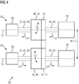
- FIG. 4 the structure of an industrial application 60 according to a first embodiment is shown schematically.
- the industrial application 60 comprises two parallel strands 62, 64, in each of which a drive means 66 is arranged.
- the drive means 66 are each formed as an electric motor or internal combustion engine and each have a drive shaft 68.
- a drive power 65 which includes a specific torque 25, transmitted to a transmission 40.
- the first gear 40 in the first strand 64 and the second gear 40 in the second strand 64 are each formed as a planetary gear 45 with a main axis 15.
- the main axes 15 have a major axis spacing 46 to each other.
- By the first and second gear 40 is in each case a transformation of the drive power 65 in terms of torque and speed.
- the substantially constant drive power 65 is in each case forwarded by the transmissions 40 via an output shaft 69 to a mechanical application 70, by means of which the purpose of the industrial application 60 is fulfilled.
- the drive means 66 are such designed such that the drive shafts 68 have opposite directions of rotation 27.
- opposing reaction moments 30 are caused in the gearboxes 40, which in turn is received by a common support device 10.
- the support device has a first and a second gear holder 12, 14, in each of which one of the gear 40 is mounted.
- the support device 10 is formed according to one of the embodiments described above.
- the industrial application 60 may be formed by appropriate choice of the mechanical application 70, for example as a mill, roller mill, cement mill, sugar mill, extruder, conveyor, rock crusher, roll crusher, roller press, roller press, pump, fan, marine propulsion or lifting device.
Landscapes
- Engineering & Computer Science (AREA)
- General Engineering & Computer Science (AREA)
- Mechanical Engineering (AREA)
- Food Science & Technology (AREA)
- General Details Of Gearings (AREA)
- Transmission Devices (AREA)
- Wind Motors (AREA)
- Structures Of Non-Positive Displacement Pumps (AREA)
- Gear Transmission (AREA)
Abstract
Description
- Die Erfindung betrifft eine Stützvorrichtung für Getriebepaar, wobei dessen Getriebe nebeneinander montiert sind. Die Erfindung betrifft auch eine Industrieapplikation, die mit einer entsprechenden Stützvorrichtung ausgestattet ist.
- Aus
EP 0 775 525 A1 ist eine Drehmomentabstützung für aufgesteckte Getriebe bekannt, über die gegenläufig drehende Walzen angetrieben werden. Die Drehmomentabstützung umfasst zwei Drehmomentstützen, die jeweils mit einem Getriebe verbunden sind. Jede Drehmomentabstützung übergreift im Wesentlichen das benachbarte Getriebe und weist ein Ende auf, an dem eine Koppelstange angebracht ist. Jede der Koppelstangen wiederum ist mit einer kurzen Drehmomentstütze verbunden, die am jeweils benachbarten Getriebe befestigt ist. Dadurch werden Reaktionsdrehmomente über die Koppelstangen als Stützkräfte in das jeweils benachbarte Getriebe eingeleitet. - Im Anlagenbau werden Anwendungen mit stetig zunehmender mechanischer Leistung angestrebt. Gleichzeitig sind für diese Anwendungen hohe Zuverlässigkeit, hohe Lebensdauer, Kompaktheit und einfache Herstellung gefordert. Für leistungsgesteigerte Anwendungen mit mehreren Getrieben besteht damit ein Bedarf an einer Stützvorrichtung für mehrere Getriebe, die in einfacher Weise eine Montage mehrerer Getriebe für Anwendungen mit erhöhter mechanischer Leistung bietet und zumindest in einem der skizzierten Aspekte eine Verbesserung bietet.
- Die Aufgabenstellung wird durch eine erfindungsgemäße Stützvorrichtung gelöst, die zur Befestigung eines Getriebepaars, also eine ersten und eines zweiten Getriebes, geeignet ausgebildet ist. Die Stützvorrichtung umfasst dazu zwei Getriebestützen, die benachbart zueinander angeordnet sind. Jede der Getriebestützen weist einen Stützflansch, also einen ersten und zweiten Stützflansch auf. Dabei ist am ersten Stützflansch eine erste Stütze befestigt. Die erste Stütze ist dazu ausgebildet, eine erste Stützkraft in den zweiten Stützflansch einzuleiten. Die erste Stützkraft wird beispielsweise durch ein Reaktionsdrehmoment hervorgerufen, das wieder durch ein Antriebsdrehmoment hervorgerufen wird, das in das erste Getriebe eingeleitet wird. In analoger Weise ist die zweite Stütze dazu ausgebildet, eine zweite Stützkraft in den ersten Stützflansch einzuleiten. Die Stützkräfte können je nach Orientierung der Antriebsdrehmomente, und damit je nach Orientierungen der Reaktionsdrehmomente, jeweils als Zug- oder Druckkräfte ausgebildet sein. Die Stützkräfte werden dabei radial, tangential und/oder einer Kombination hieraus in den jeweiligen Stützflansch eingeleitet. Dadurch wird insgesamt eine vorteilhafte Lagerung des ersten und zweiten Getriebes während eines bestimmungsgemäßen Betriebs erzielt. Erfindungsgemäß ist die zweite Stütze dazu ausgebildet, dass sich die erste Stütze durch die zweite Stütze erstreckt. Dies erlaubt eine enge räumliche Anordnung der beiden Stützen und ermöglicht eine günstige und verformungsarme Befestigung der Stützen an ihren jeweiligen Stützflanschen. Infolgedessen können bei gleichbleibender Masse der Stützarme höhere Stützkräfte in die Stützflansche eingeleitet werden. Alternativ können gleichbleibende Stützkräfte bei reduzierter Masse der Stützarme in die Stützflansche eingeleitet werden. Die so erzielte gesteigerte Materialausnutzung bietet auch ein erhöhtes Maß an Lebensdauer, und damit Zuverlässigkeit. Die erfindungsgemäße Stützvorrichtung ist in einfacher Weise herstellbar und inspizierbar, und somit kosteneffizient. Die erfindungsgemäße Stützvorrichtung wird dabei für Getriebe verwendet, die dazu ausgebildet sind, Leistungen von 100 kW bis 10 MW, insbesondere 200 kW bis 7,0 MW zu übertragen. Die erfindungsgemäße Stützvorrichtung kann auch statt mit Getrieben mit Antriebsmitteln, wie beispielsweise Elektromotoren oder Hydraulikmotoren, verbunden werden.
- In einer Ausführungsform der beanspruchten Stützvorrichtung ist die erste Stütze einlaschig ausgebildet und die zweite Stütze zweilaschig. Unter einlaschig ist hierbei zu verstehen, dass die erste Stütze zumindest abschnittsweise nur eine im Wesentlichen flächige Komponente umfasst und in diesem Abschnitt mechanische als Scheibe beschreibbar ist. Unter zweilaschig ist im Sinne der beanspruchten Lösung zu verstehen, dass die zweite Stütze zumindest abschnittsweise nur zwei im Wesentlichen parallel angeordnete flächige Komponenten umfasst, die wiederum in den entsprechenden Abschnitten jeweils als Schreibe beschreibbar sind. Dadurch weist die zweite Stütze einen lichten Zwischenraum auf, der dazu ausgebildet ist, zumindest abschnittsweise die einlaschige erste Stütze aufzunehmen. Eine Kombination einer einlaschigen ersten Stütze und einer zweilaschigen zweiten Stütze erlaubt in einfacher Weise ein Erstrecken der ersten Stütze durch die zweite Stütze. Entsprechende Stützen sind in einfacher Weise schnell und kosteneffizient herstellbar. Ferner können einlaschige und zweilaschige Stützen mit Aussparungen ausgebildet sein, die eine Gewichtersparnis bei den Stützen erlauben, und so die Montage der beanspruchten Stützvorrichtung vereinfachen. Darüber hinaus sind entsprechend einlaschige und zweilaschige Stützen in einfacher Weise mechanisch berechenbar, was eine schnelle Anpassung der beanspruchten Lösung an unterschiedliche Anwendungsfälle erlaubt.
- Darüber hinaus können die erste und zweite Stütze in der beanspruchten Stützvorrichtung auch zweischnittig voneinander getrennt angeordnet sein. Unter einer zweischnittigen Trennung ist zu verstehen, dass zwei Schnittebenen erforderlich sind, um die erste Stütze von der zweiten Stütze im Sinne der Technischen Mechanik freizuschneiden. Hierdurch wird insgesamt ein einfacher Aufbau gewährleistet.
- In einer weiteren Ausführungsform der Stützvorrichtung kann die erste Stütze einen Stützarm aufweisen, der in einer Flanschhauptebene des ersten Stützflansches ausgebildet ist. Eine Flanschhauptebene ist eine Ebene, die im Wesentlichen senkrecht zu mindestens einer Hauptachse eines Getriebes steht, das an der Stützvorrichtung montiert ist. Die Hauptachse ist dabei beispielsweise die Achse, um die sich eine Getriebeeingangswelle und/oder Getriebeausgangswelle in einem bestimmungsgemäßen Betrieb dreht. Der Stützarm an der ersten Stütze ist dazu ausgebildet, die zweite Getriebestütze, und damit den zweiten Stützflansch zu übergreifen. Der Stützarm am ersten Stützflansch ist so dazu ausgebildet, eine Stützkraft lateral außen in den zweiten Stützflansch einzuleiten. Durch eine Positionierung des Stützarms in der Flanschhauptebene wirken Radialkräfte auf den Stützarm mit einer reduzierten Hebellänge in Axialrichtung, und damit im Wesentlichen frei von Biegelasten, auf den ersten Stützflansch ein. Der erste Stützflansch wird damit in einem bestimmungsgemäßen Betrieb durch den Stützarm damit in höchstens vernachlässigbarem Maß auf Biegung beansprucht. Ein Aspekt der vorgeschlagenen Lösung besteht in der Erkenntnis, dass eine Biegebeanspruchung von Stützflanschen die mechanische Beanspruchbarkeit von Stützflanschen, und damit von entsprechenden Stützvorrichtungen, wesentlich mitbestimmt. Infolgedessen bietet eine erste Stütze, deren Stützarm sich im Wesentlichen in einer Flanschhauptebene erstreckt, eine Steigerung an mechanischer Beanspruchbarkeit der Stützvorrichtung, und damit eine Möglichkeit für eine Leistungssteigerung einer angeschlossenen mechanischen Anwendung. Gleichermaßen werden durch die gesteigerte Beanspruchbarkeit die Lebensdauer und die Zuverlässigkeit des ersten Stützflansches erhöht. Darüber hinaus werden so Biegebeanspruchungen von lösbaren Befestigungsmitteln und auf diese einwirkende Axial- und Radialkräfte reduziert, mit denen die erste Stütze an der ersten Flanschstütze befestigt ist. Infolgedessen sind in der beanspruchten Stützvorrichtung beispielsweise Schrauben als lösbares Befestigungsmittel einsetzbar. Die Verwendung von aufwendigen lösbaren Befestigungsmitteln, wie beispielsweise Passschrauben, ist somit nicht durchgängig erforderlich oder vorzugsweise entbehrlich. Derartige aufwendige Befestigungsmittel können bei der beanspruchten Lösung durch Schrauben oder Stifte mit verringerten Größen, niedrigeren Güten, wie beispielsweise Festigkeitsklassen, ersetzt werden. Ferner kann der Stützarm kann im Wesentlichen symmetrisch in der Flanschhauptebene ausgebildet sein. Eine derartige Ausbildung des Stützarms wird auch als reitende Anordnung bezeichnet.
- Des Weiteren kann in der beanspruchten Stützvorrichtung die zweite Stütze zwei Stützarme aufweisen, die auf voneinander abgewandten Stirnseiten des zweiten Stützflansches ausgebildet sind. Dabei liegt zwischen den Stützarmen ein lichter Zwischenraum vor, der zu einem zumindest teilweisen Aufnehmen des Stützarms der zweiten Stütze dient. Der lichte Zwischenraum zwischen den Stützarmen der zweiten Stütze wird so durch eine Flanschhauptebene des zweiten Stützflanschs im Wesentlichen symmetrisch geteilt. Dadurch wird, analog zur reitenden Anordnung des Stützarms der ersten Stütze, der zweite Stützflansch nur mit einer reduzierten Biegelast beansprucht, also dessen Biegebeanspruchung verringert. Hierdurch werden die Vorzüge der beanspruchten Lösung in stärkerem Umfang verwirklicht.
- Die Stützvorrichtung kann auch am ersten und/oder zweiten Stützarm an dessen Ende mit einer Strebe ausgestattet sein. Die Strebe, die am Ende des Stützarms der ersten Stütze angebracht ist, ist auch mit dem zweiten Stützflansch gekoppelt. Die Strebe, die am Ende des Stützarms der zweiten Stütze angebracht ist, ist auch mit dem ersten Stützflansch gekoppelt. Die Streben können jeweils mit einer Augenstabverbindung mit dem entsprechenden Stützarm gekoppelt sein und so eine Stützkraft auf den ersten bzw. zweiten Stützflansch übertragen. Die Strebe ist zur Übertragung einer Zugkraft und/oder Druckkraft ausgebildet, so dass unterschiedliche Belastungszustände, also Drehrichtungen von Getriebeeingangswellen, durch die Stützvorrichtung aufnehmbar sind.
- Ferner können die Streben jeweils zu einer im Wesentlichen biegemomentfreien Einleitung einer Zugkraft oder Druckkraft in den ersten bzw. zweiten Stützflansch ausgebildet sein. Dazu sind die Streben jeweils derart mit der ersten bzw. zweiten Stütze und dem ersten bzw. zweiten Stützflansch verbunden, dass die übertragene Zugkraft oder Druckkraft auch in der ersten bzw. zweiten Flanschhauptebene liegt. Beispielsweise kann die Zugkraft oder Druckkraft frei von einer Axialkomponente in den ersten bzw. zweiten Stützflansch eingeleitet werden. Dabei ist die Zugkraft oder Druckkraft, bezogen auf die Hauptachse des jeweiligen Getriebes, als Kombination einer Radialkraft und einer Tangentialkraft darstellbar. Zu diesem Zweck kann am ersten und/oder zweiten Stützflansch eine entsprechende Strebenverankerung angebracht sein.
- In einer weiteren Ausführungsform der Stützvorrichtung kann die Strebenverankerung am ersten und/oder zweiten Stützflansch an der ersten bzw. zweiten Stütze befestigt sein. Die Strebenverankerung kann dabei insbesondere einstückig mit der ersten bzw. zweiten Stütze ausgebildet sein, also angeformt sein. Dadurch wird die Herstellung des ersten und/oder zweiten Stützflansches vereinfacht. Insbesondere kann der erste und/oder zweite Stützflansch damit bezüglich der Hauptachse des zugehörigen Getriebes im Wesentlichen rotationssymmetrisch ausgebildet sein. Ferner wird durch ein Zusammenfassen der ersten bzw. zweiten Stütze mit der zugehörigen Strebenverankerung die Anzahl der Bauteile reduziert, insbesondere separate Befestigungsmittel für die Strebenverankerungen eingespart, was wiederum eine vereinfachte Montage gewährleistet. Ferner ist erlaubt das Zusammenfassen von Stützflansch und Strebenverankerung, eine konstruktive Anpassung eines Übergangs zwischen der Strebenverankerung und dem zugehörigen Stützarm. Folglich ist der Übergang von der Strebenverankerung zum Stützarm gezielt belastungs- und materialgerecht konstruierbar und eine erhöhte Materialausnutzung erzielbar.
- Alternativ kann auch mindestens eine der Strebenverankerungen unmittelbar an den ersten bzw. zweiten Stützflansch angeformt sein. Eine an den ersten oder zweiten Stützflansch angeformte Strebenverankerung bietet eine einfache Möglichkeit, eine von einer Strebe eingeleitete Stützkraft belastungs- und materialgerecht in den ersten oder zweiten Stützflansch einzuleiten. Ferner werden durch eine angeformte Strebenverankerung gegenüber separaten Strebenverankerungen in Differentialbauweise Befestigungsmittel und Montageaufwand einsgespart.
- Darüber hinaus können der erste und/oder zweite Stützflansch im Bereich der jeweiligen Flanschhauptebene zumindest abschnittsweise radial verkürzt ausgebildet sein. Eine solche radiale Verkürzung kann als eine Abweichung von einer rotationssymmetrischen Grundform des ersten und/oder zweiten Stützflanschs ausgebildet sein. Dies kann insbesondere eine abgeschnittene Flanschkontur sein. Der radial verkürzte erste und/oder zweite Stützflansch dient dazu, einen Hauptachsenabstand zwischen den Hauptachsen der Getriebe zu verringern. Dazu können die Stützflansche derart gegenüberliegend angeordnet sein, dass die Flanschhauptebenen der beiden Stützflansche im Wesentlichen identisch sind. Durch die radiale Verkürzung der Stützflansche wird so eine kompaktere Positionierung der Getriebe ermöglicht. Die beanspruchte Lösung ist damit auch bei mechanischen Anwendungen verwendbar, die einen engen Hauptachsenabstand erfordern. Dadurch weist die beanspruchte Stützvorrichtung ein vergrößertes Einsatzspektrum auf. Ebenso kann bei bestehenden mechanischen Anwendungen, die denen ein maximal verfügbarer Bauraum durch einen Hauptachsenabstand definiert ist, durch die beanspruchte Lösung ein leistungsstärkerer Antrieb und/oder Getriebe eingesetzt werden. Bestehende Industrieapplikationen sind durch die beanspruchte Stützvorrichtung somit in einfacher Weise ausbaubar und eine erhöhte Leistungsdichte erzielbar.
- Des Weiteren kann der erste und/oder zweite Stützflansch als Gehäusekomponente eines Getriebes ausgebildet sein. Der erste und/oder zweite Stützflansch kann dabei insbesondere als abtriebsseitiger Gehäuseabschnitt ausgebildet sein, in dem sich eine Abtriebswelle des korrespondierenden Getriebes erstreckt. Hierdurch wird ein hoher Grad in Integration beim Aufbau einer Industrieapplikation erzielt, die mit einer entsprechenden Stützvorrichtung ausgestattet ist.
- Die zugrundeliegende Aufgabenstellung wird auch durch eine erfindungsgemäße Industrieapplikation gelöst. Die Industrieapplikation weist ein erstes Getriebe auf, dem über eine erste Getriebeeingangswelle Antriebsleistung, also ein Antriebsdrehmoment bei einer Betriebsdrehzahl, zuführbar ist. Die Industrieapplikation umfasst auch ein zweites Getriebe, dem im Wesentlichen analog zum ersten Getriebe, über eine zweite Getriebeeingangswelle Antriebsleistung zuführbar ist. Die erste und zweite Getriebeeingangswellen weisen in einem bestimmungsgemäßen Betrieb gegenläufige Drehrichtungen auf, durch die entsprechende Reaktionsdrehmomente hervorgerufen werden. Das erste und zweite Getriebe sind an einer Stützvorrichtung befestigt, in der durch die Antriebsleistungen die Reaktionsmomente hervorgerufen werden und in der sich abhängig von den vorliegenden Antriebsleistungen ein Belastungszustand einstellt. Zur einer vorteilhaften Aufnahme des vorliegenden Belastungszustands ist die Stützvorrichtung gemäß einer der oben beschriebenen Ausführungsformen ausgebildet. Durch die entsprechende Stützvorrichtung wird die Montage der Industrieapplikation vereinfacht. Durch die erhöhte Zuverlässigkeit und Lebensdauer der Stützvorrichtung wird der Wartungsaufwand für die Industrieapplikation reduziert. Ferner kann die Industrieapplikation durch die gesteigerte mechanische Beanspruchbarkeit der Stützvorrichtung mit einer erhöhten Antriebsleistung ausgestattet werden, und so die Produktivität der Industrieapplikation erhöht werden. Die Industrieapplikation kann beispielsweise als Mühle, Wälzmühle, Zementmühle, Zuckermühle, Extruder, Förderanlage, Gesteinsbrecher, Walzenbrecher, Walzenpresse, Rollpresse, Pumpe, Ventilator, Schiffsantrieb oder Hebevorrichtung ausgebildet sein.
- Ferner kann das erste und/oder zweite Getriebe als Planetengetriebe ausgebildet sein. Planetengetriebe bieten eine hohe Leistungsdichte und erlauben es, die gesteigerte mechanische Beanspruchbarkeit der Stützvorrichtung in besonderem Maß auszunutzen. Dadurch werden die Vorteile der beanspruchten Stützvorrichtung insgesamt in einem hohen Maß erzielt. Alternativ kann jedes der Getriebe jeweils auch als Stirnradgetriebe, als Schneckengetriebe, oder als Kegelradgetriebe ausgebildet sein.
- Die Erfindung wird im Folgenden anhand einzelner Ausführungsformen beschrieben. Die Merkmale der einzelnen Ausführungsformen sind dabei untereinander kombinierbar. Die Figuren sind insoweit in gegenseitiger Ergänzung zu lesen, dass gleiche Bezugszeichen in den Figuren auch die gleiche technische Bedeutung haben. Es zeigen im Einzelnen:
- FIG 1
- eine Schrägansicht einer ersten Ausführungsform der beanspruchten Stützvorrichtung;
- FIG 2
- eine Detailansicht der ersten Ausführungsform der beanspruchten Stützvorrichtung in Längsschnittansicht;
- FIG 3
- eine weitere Detailansicht der ersten Ausführungsform der beanspruchten Stützvorrichtung in Längsschnittansicht;
- FIG 4
- eine schematische Übersicht einer ersten Ausführungsform einer beanspruchten Industrieapplikation.
-
FIG 1 zeigt schematisch eine erste Ausführungsform einer erfindungsgemäßen Stützvorrichtung 10, die eine erste und zweite Getriebehalterung 12, 14 aufweist, die jeweils dazu ausgebildet sind, daran ein nicht näher dargestelltes Getriebe 40 zu befestigen. Die erste Getriebehalterung 12 weist einen ersten Stützflansch 16 auf und die zweite Getriebehalterung 14 einen zweiten Stützflansch 18. Im montierten Zustand werden in die Getriebe 40, die sich um ihre Hauptachsen 15 drehen, Drehmomente 25 eingeleitet. Die Hauptachsen 15 weisen zueinander einen Hauptachsenabstand 46 auf. Dabei weisen die Drehmomente 25 entgegengesetzte Drehrichtungen 27 auf. Infolgedessen werden in den Getriebehalterungen 12, 14, und damit in den Stützflanschen 16, 18 Reaktionsdrehmomente 30 hervorgerufen. Dabei weisen die Reaktionsdrehmomente 30 jeweils Reaktionsrichtungen 31 auf, die den entsprechenden eingeleiteten Drehmomenten 25 des Getriebes 40 an der jeweiligen Getriebehalterung 12, 14 entgegengesetzt sind. Der erste und zweite Stützflansch 16, 18 sind damit entgegengesetzt orientierten Reaktionsdrehmomenten 30 unterworfen. Am ersten Stützflansch 16 ist über eine Mehrzahl an Befestigungsmitteln 33, die in entsprechenden Ausnehmungen 32 aufgenommen sind, eine erste Stütze 22 angebracht, so dass das Reaktionsmoment 30, das auf den ersten Stützflansch 16 einwirkt, auch auf die erste Stütze 16 einwirkt. Die erste Stütze 22 weist einen Stützarm 26 auf, der den benachbart angeordneten zweiten Stützflansch 18 im Wesentlichen übergreift. Dabei ist der Stützarm 26 der ersten Stütze 22 im Wesentlichen in einer Flanschhauptebene 20 des ersten Stützflansches 16 angeordnet. Unter der Flanschhauptebene 20 ist dabei die Ebene zu verstehen, die durch die Ausnehmungen 32 für die Befestigungsmittel 33 definiert ist, und dabei im Wesentlichen senkrecht zu einer entsprechenden Hauptachse 15 eines Getriebe 40 liegt. Die Anordnung des Stützarms 26 der ersten Stütze 22 in der Flanschhauptebene 20 des ersten Stützflansches 16 wird dabei auch als reitende Anordnung bezeichnet. - An einem Stützarm-Ende 28 ihres Stützarms 26 ist die erste Stütze 22 über eine Augenstabverbindung 36 mit einer Strebe 34 gelenkig verbunden. Die Strebe 34 am entsprechenden Stützarm-Ende 28 wiederum ist über eine weitere Augenstabverbindung 36 mit einem Befestigungslager 23 verbunden, das wiederum einstückig mit der zweiten Stütze 24 ausgebildet ist. Die zweite Stütze 24 ist über Befestigungselemente 33 mit dem zweiten Stützflansch 18 verbunden. Ein Reaktionsdrehmoment 30, das sich durch das Drehmoment 25 eines Getriebes 40 an der ersten Getriebehalterung 12 ergibt, wird über den Stützarm 26 der ersten Stütze 22 in den zweiten Stützflansch 18 eingeleitet. Dabei wird durch das Befestigungslager 23 am zweiten Stützflansch 18 auf die entsprechende Strebe 34 eine Zugkraft 35 ausgeübt. In korrespondierender Form wird ein Reaktionsdrehmoment 30, das sich infolge eines Drehmoments 25 eines Getriebes 40 einstellt, das an der zweiten Getriebehalterung 14 angebracht ist, über die zweite Stütze 24 in den ersten Stützflansch 16 eingeleitet.
- Die erste Stütze 22 weist nur einen Stützarm 26 auf und ist somit einlaschig ausgebildet. Die zweite Stütze 24 weist zwei Stützarme 26 auf, die in Wesentlichen kongruent ausgebildet sind und beanstandet zueinander am zweiten Stützflansch 18 angebracht sind. Damit ist die zweite Stütze 24 zweilaschig ausgebildet. Die Stützarme 26 der zweiten Stütze 24 sind derart voneinander beanstandet angeordnet, dass sich der Stützarm 26 der ersten Stütze 22 durch einen lichten Raum 29 zwischen den Stützarmen 26 der zweiten Stütze 24 erstreckt. Dadurch erstreckt sich die erste Stütze 22 durch die zweite Stütze 24. Der Stützarm 26 der ersten Stütze 22 und die Stützarme 26 der zweiten Stütze 26 sind folglich zweischnittig voneinander getrennt. Ferner ist jeder der Stützarme 26 in der Stützvorrichtung 10 mit Aussparungen 21 versehen, durch die eine verbesserte Materialausnutzung der Stützarme 26 erzielt wird. Die Anordnung der Stützarme 26 der ersten und zweiten Stütze 24 erlaubt es, dass in den Flanschhauptebenen 20 des ersten und zweiten Stützflansches 16, 18 im Wesentlichen rein koplanare Kräfte und Drehmomente vorliegen, und somit der erste und zweite Stützflansch 16, 18 im Wesentlichen biegemomentfrei sind. Dieser Aspekt wird in
FIG. 2 näher dargestellt. Ferner sind der erste und zweite Stützflansch 16, 18 an einander zugewandten Seiten im Bereich der Flanschhauptebenen 20 abschnittsweise radial verkürzt ausgebildet. Infolgedessen ist der Hauptachsenabstand 46 gegenüber den aus dem Stand der Technik bekannten Lösungen verringert. - In
FIG 2 ist schematisch eine Detailansicht der Ausführungsform gemäßFIG 1 im Bereich der ersten Getriebehalterung 12 dargestellt. Die erste Stütze 22 ist über zumindest ein Befestigungsmittel 33 am ersten Stützflansch 16 befestigt, der über entsprechende Ausnehmungen 32 zur Aufnahme der Befestigungselemente 33 verfügt. Das zumindest eine Befestigungsmittel 33 ist dabei als Schraube mit Mutter ausgebildet. Der Stützarm 26 ist derart ausgebildet und am ersten Stützflansch 16 angeordnet, dass die Flanschhauptebene 20 des ersten Stützflansches 16 den Stützarm 26 der ersten Stütze 22 im Wesentlichen symmetrisch teilt. Dabei ist der Stützarm 26 einlaschig ausgebildet. Auf den Stützarm 26 wirkt eine Biegekraft 38 ein, die sich durch die Zugkraft 35 ergibt, die gemäßFIG 1 in der Strebe 34 am Stützarm-Ende 28 des Stützarms 26 der ersten Stütze 22 vorliegt. Dadurch, dass die erste Stütze 22 bezogen auf die Flanschhauptebene 20 des ersten Stützflansches 16 im Wesentlichen symmetrisch angeordnet ist, werden Biegemomente 42, durch die dem Stützarm 26 und/oder dem ersten Stützflansch 16 eine Auslenkung 44 entlang einer Hauptdrehrichtungen 15 aufprägbar ist, zu Null. Damit werden Biegebeanspruchungen durch Biegemomente 42 im Sinne vonFIG 2 in der beanspruchten Stützvorrichtung 10 vermieden. Insbesondere wird eine mechanische Beanspruchung im Bereich einer Stützarmwurzel 39 reduziert. Durch das Vermeiden der Biegemomente 42 liegt im Betrieb der beanspruchten Stützvorrichtung 10 eine günstigere Materialbeanspruchung vor. Dies erlaubt es, an die Stützvorrichtung 10 Getriebe 40 anzuschließen, in denen gesteigerte Drehmomente 25 vorliegen und gleichzeitig die Materialbeanspruchung im ersten Stützflansch 16 konstant zu halten. - Korrespondierend zu
FIG 2 ist inFIG 3 eine Detailansicht der Ausführungsform ausFIG 1 abgebildet.FIG 3 zeigt einen Längsschnitt im Bereich des zweiten Stützflansches 18 an der zweiten Getriebehalterung 14. Am zweiten Stützflansch 18 ist eine zweite Stütze 24 über Befestigungsmittel 33 angebracht, die als Schrauben mit Muttern ausgebildet sind. Dazu sind die Befestigungsmittel 33 in Ausnehmungen 32 in der zweiten Stütze 22 und dem zweiten Stützflansch 18 aufgenommen. Die zweite Stütze 18 weist zwei Stützarme 26 auf, die im Wesentlichen parallel zueinander sind. Zwischen den Stützarmen 26 ist ein lichter Raum 29 ausgebildet, der dazu ausgebildet ist, einen Stützarm 26 einer ersten Stütze 22 wie inFIG 2 aufzunehmen. Infolgedessen ist es möglich, dass sich die erste Stütze 22 gemäßFIG 2 durch die zweite Stütze 24 erstreckt. Die Stützarme 26 der zweiten Stütze 24 sind symmetrisch zu einer Flanschhauptebene 20 ausgerichtet, die sich im Wesentlichen mittig durch den zweiten Stützflansch 18 erstreckt. Auf jeden der Stützarme 26 gemäßFIG 3 wirkt eine Biegekraft 38 ein, die durch eine Zugkraft 35 hervorgerufen wird, die im bestimmungsgemäßen Betrieb durch eine Zugkraft 35 an zumindest einem Stützarm-Ende 28 auftritt. Die Biegekräfte 38 wirken im Wesentlichen parallel zur Flanschhauptebene 20, so dass Biegemomente 42, die dazu geeignet sind, eine Auslenkung 44 der Stützarme 26 entlang der Hauptdrehachse 15 hervorzurufen, zu Null werden. Die so erzielte Reduzierung der Materialbeanspruchung gewährleistet eine erhöhte Lebensdauer der zweiten Stütze 18. Alternativ kann so auch das Drehmoment 25, das über ein Getriebe 40 übertragen wird, das am zweiten Getriebehalter 14 angebracht ist, erhöht werden, und so das für die zweite Stütze 24 und den zweiten Stützflansch 18 stärker ausnutzen. - In
FIG 4 ist schematisch der Aufbau einer Industrieapplikation 60 gemäß einer ersten Ausführungsform dargestellt. Die Industrieapplikation 60 umfasst zwei parallele Stränge 62, 64, in denen jeweils ein Antriebsmittel 66 angeordnet ist. Die Antriebsmittel 66 sind jeweils als Elektromotor oder Verbrennungsmotor ausgebildet und verfügen jeweils über eine Antriebswelle 68. Über die Antriebswelle 68 wird eine Antriebsleistung 65, die ein bestimmtes Drehmoment 25 umfasst, an ein Getriebe 40 übertragen. Das erste Getriebe 40 im ersten Strang 64 und das zweite Getriebe 40 im zweiten Strang 64 sind jeweils als Planetengetriebe 45 mit einer Hauptachse 15 ausgebildet. Die Hauptachsen 15 weisen zueinander einen Hauptachsenabstand 46 auf. Durch das erste und zweite Getriebe 40 erfolgt jeweils eine Umformung der Antriebsleistung 65 in puncto Drehmoment und Drehzahl. Diese Umformung umfasst, dass bei der eine Steigerung des Drehmoments zu einer Senkung der Drehzahl führt und umgekehrt. Die im Wesentlichen gleichbleibende Antriebsleistung 65 wird jeweils von den Getrieben 40 jeweils über eine Abtriebswelle 69 an eine mechanische Anwendung 70 weitergeleitet, durch die der Zweck der Industrieapplikation 60 erfüllt wird. Die Antriebsmittel 66 sind derart ausgebildet, dass die Antriebswellen 68 gegenläufige Drehrichtungen 27 aufweisen. Dadurch werden in den Getrieben 40 gegenläufige Reaktionsmomente 30 hervorgerufen, die wiederum durch eine gemeinsame Stützvorrichtung 10 aufgenommen wird. Die Stützvorrichtung weist eine erste und eine zweite Getriebehalterung 12, 14 auf, in denen jeweils eines der Getriebe 40 montiert ist. Die Stützvorrichtung 10 ist dabei gemäß einer der oben beschriebenen Ausführungsformen ausgebildet. Die Industrieapplikation 60 kann durch entsprechende Wahl der mechanischen Anwendung 70 beispielsweise als Mühle, Wälzmühle, Zementmühle, Zuckermühle, Extruder, Förderanlage, Gesteinsbrecher, Walzenbrecher, Walzenpresse, Rollpresse, Pumpe, Ventilator, Schiffsantrieb oder Hebevorrichtung ausgebildet sein.
Claims (13)
- Stützvorrichtung (10) für ein erstes und ein zweites Getriebe (40) oder für Antriebsmittel (66), umfassend einen ersten und einen zweiten Stützflansch (16, 18), wobei am ersten Stützflansch (16) eine erste Stütze (22) zu einer Einleitung einer ersten Stützkraft () in den zweiten Stützflansch (18) angebracht ist und am zweiten Stützflansch (18) eine zweite Stütze (24) zu einer Einleitung einer zweiten Stützkraft () in den ersten Stützflansch (16) angebracht ist, dadurch gekennzeichnet, dass sich die erste Stütze (22) durch die zweite Stütze (24) erstreckt.
- Stützvorrichtung (10) nach Anspruch 1, dadurch gekennzeichnet, dass die erste Stütze (22) einlaschig ausgebildet ist und die zweite Stütze (24) zweilaschig ausgebildet ist.
- Stützvorrichtung (10) nach Anspruch 1 oder 2, dadurch gekennzeichnet, dass die erste und zweite Stütze (22, 24) zweischnittig voneinander getrennt sind.
- Stützvorrichtung (10) nach einem der Ansprüche 1 bis 3, dadurch gekennzeichnet, dass die erste Stütze (22) einen Stützarm (26) aufweist, der in einer Flanschhauptebene (20) des ersten Stützflansches (16) angebracht ist.
- Stützvorrichtung (10) nach einem der Ansprüche 1 bis 4, dadurch gekennzeichnet, dass die zweite Stütze (24) zwei Stützarme (26) aufweist, die auf voneinander abgewandten Stirnflächen () des zweiten Stützflansches (18) angebracht sind.
- Stützvorrichtung (10) nach einem der Ansprüche 1 bis 5, dadurch gekennzeichnet, dass an einem der Stützarme (26) an einem Ende (28) eine Strebe (34) angebracht ist, die zu einer Einleitung einer Zugkraft und/oder Druckkraft (35) ausgebildet ist.
- Stützvorrichtung (10) nach Anspruch 6, dadurch gekennzeichnet, dass zumindest eine der Streben (34) zur einer, bezogen auf eine Flanschhauptebene (20), biegemomentfreien Einleitung einer Zugkraft oder Druckkraft (35) in den ersten bzw. zweiten Stützflansch (16, 18) ausgebildet ist.
- Stützvorrichtung (10) nach Anspruch 6 oder 7, dadurch gekennzeichnet, dass die erste und/oder zweite Stütze (22, 24) mit einem Befestigungslager (23) ausgestattet ist.
- Stützvorrichtung (10) nach einem der Ansprüche 1 bis 7, dadurch gekennzeichnet, dass mindestens eines der Befestigungslager (23) an den ersten bzw. zweiten Stützflansch (16, 18) angeformt ist.
- Stützvorrichtung (10) nach einem der Ansprüche 1 bis 9, dadurch gekennzeichnet, dass der erste und/oder zweite Stützflansch (16, 18) zur Verringerung eines Hauptachsenabstands (46) zwischen dem ersten und zweiten Getriebe (40) abschnittsweise radial verkürzt ausgebildet sind.
- Stützvorrichtung (10) nach einem der Ansprüche 1 bis 10, dadurch gekennzeichnet, dass der erste und/oder zweite Stützflansch (16, 18) als Gehäusekomponente des ersten bzw. zweiten Getriebes (40) ausgebildet ist.
- Industrieapplikation (60), umfassend ein erstes Getriebe (40), dem über eine erste Antriebswelle (68) Antriebsleistung (65) zuführbar ist, und ein zweites Getriebe (), dem über eine zweite Antriebswelle (68) Antriebsleistung (65) zuführbar ist, wobei die erste und zweite Antriebswelle (68) gegensinnige Drehrichtungen (27) aufweisen und das erste und das zweite Getriebe (40) an einer Stützvorrichtung (10) angebracht sind, dadurch gekennzeichnet, dass die Stützvorrichtung (10) nach einem der Ansprüche 1 bis 11 ausgebildet ist.
- Industrieapplikation (60) nach Anspruch 12, dadurch gekennzeichnet, dass das erste und/oder zweite Getriebe (40) als Planetengetriebe (45) ausgebildet ist.
Priority Applications (5)
| Application Number | Priority Date | Filing Date | Title |
|---|---|---|---|
| ES18160708T ES2831032T3 (es) | 2018-03-08 | 2018-03-08 | Dispositivo de soporte para un par de giro de engranajes y aplicación industrial |
| EP18160708.6A EP3536404B2 (de) | 2018-03-08 | 2018-03-08 | Stützvorrichtung für getriebepaar und industrieapplikation |
| FIEP18160708.6T FI3536404T4 (fi) | 2018-03-08 | 2018-03-08 | Vaihteistoparia varten tarkoitettu tukilaite ja teollisuuskäyttö |
| US16/295,728 US10670135B2 (en) | 2018-03-08 | 2019-03-07 | Support apparatus for gearing pair and industrial application |
| CN201910175812.2A CN110242739B (zh) | 2018-03-08 | 2019-03-08 | 用于传动机构对的支撑装置和工业应用 |
Applications Claiming Priority (1)
| Application Number | Priority Date | Filing Date | Title |
|---|---|---|---|
| EP18160708.6A EP3536404B2 (de) | 2018-03-08 | 2018-03-08 | Stützvorrichtung für getriebepaar und industrieapplikation |
Publications (3)
| Publication Number | Publication Date |
|---|---|
| EP3536404A1 true EP3536404A1 (de) | 2019-09-11 |
| EP3536404B1 EP3536404B1 (de) | 2020-08-05 |
| EP3536404B2 EP3536404B2 (de) | 2024-08-14 |
Family
ID=61599064
Family Applications (1)
| Application Number | Title | Priority Date | Filing Date |
|---|---|---|---|
| EP18160708.6A Active EP3536404B2 (de) | 2018-03-08 | 2018-03-08 | Stützvorrichtung für getriebepaar und industrieapplikation |
Country Status (5)
| Country | Link |
|---|---|
| US (1) | US10670135B2 (de) |
| EP (1) | EP3536404B2 (de) |
| CN (1) | CN110242739B (de) |
| ES (1) | ES2831032T3 (de) |
| FI (1) | FI3536404T4 (de) |
Families Citing this family (4)
| Publication number | Priority date | Publication date | Assignee | Title |
|---|---|---|---|---|
| ES2831032T3 (es) * | 2018-03-08 | 2021-06-07 | Flender Gmbh | Dispositivo de soporte para un par de giro de engranajes y aplicación industrial |
| EP3736045A1 (de) * | 2019-05-10 | 2020-11-11 | Flender GmbH | Stützvorrichtung für zwei getriebe sowie vorrichtung mit einer solchen stützvorrichtung |
| SE543582C2 (en) * | 2019-06-25 | 2021-04-06 | Valmet Oy | A torque reaction arrangement for pulp washers and a pulp washer including the arrangement |
| DE102020103823B3 (de) * | 2020-02-13 | 2021-01-21 | Matthews International GmbH | Drehmomentstütze zum Abfangen von Antriebsmomenten und Walzenanordnung mit einer Drehmomentstütze |
Citations (3)
| Publication number | Priority date | Publication date | Assignee | Title |
|---|---|---|---|---|
| DE4019363C1 (en) * | 1990-06-18 | 1991-08-14 | A. Friedr. Flender Ag, 4290 Bocholt, De | Roller drive for press - has torque supports connected directly on defined load lines |
| EP0775525A1 (de) | 1995-11-21 | 1997-05-28 | A. Friedr. Flender Ag | Drehmomentabstützung |
| DE19619110A1 (de) * | 1996-05-11 | 1997-11-13 | Santasalo Gmbh | Walzenpaar |
Family Cites Families (10)
| Publication number | Priority date | Publication date | Assignee | Title |
|---|---|---|---|---|
| DE3901060A1 (de) * | 1989-01-16 | 1990-07-19 | Kloeckner Humboldt Deutz Ag | Zweiwalzenmaschine, insbesondere walzenbrecher |
| DE4024109A1 (de) * | 1990-07-30 | 1992-02-06 | Kloeckner Humboldt Deutz Ag | Zweiwalzenmaschine, insbesondere rollenpresse |
| GB2252517A (en) * | 1991-02-07 | 1992-08-12 | Smidth & Co As F L | Roller press with torque counter balancing |
| DE4404634A1 (de) * | 1994-02-14 | 1995-08-17 | Krupp Polysius Ag | Walzenmühle |
| DE19822341B4 (de) * | 1998-05-19 | 2007-10-18 | Gebr. Eickhoff Maschinenfabrik U. Eisengiesserei Mbh | Antriebsvorrichtung für zwei gegenläufig angetriebene Walzen |
| DE29921305U1 (de) | 1999-12-03 | 2000-04-06 | P.I.V. Antrieb Werner Reimers Gmbh & Co Kg, 61352 Bad Homburg | Drehmomentstütze für Walzenantriebe |
| CN102824936A (zh) * | 2012-09-24 | 2012-12-19 | 四川皇龙智能破碎技术股份有限公司 | 可自动调节压辊间隙的啮合式挤压破碎机 |
| EP2982442A1 (de) * | 2014-08-05 | 2016-02-10 | Siemens Aktiengesellschaft | Antriebsanordnung für einen Walzenbrecher |
| DE102014016973A1 (de) † | 2014-11-18 | 2016-05-19 | Eickhoff Antriebstechnik Gmbh | Antriebsvorrichtung |
| ES2831032T3 (es) * | 2018-03-08 | 2021-06-07 | Flender Gmbh | Dispositivo de soporte para un par de giro de engranajes y aplicación industrial |
-
2018
- 2018-03-08 ES ES18160708T patent/ES2831032T3/es active Active
- 2018-03-08 EP EP18160708.6A patent/EP3536404B2/de active Active
- 2018-03-08 FI FIEP18160708.6T patent/FI3536404T4/fi active
-
2019
- 2019-03-07 US US16/295,728 patent/US10670135B2/en active Active
- 2019-03-08 CN CN201910175812.2A patent/CN110242739B/zh active Active
Patent Citations (3)
| Publication number | Priority date | Publication date | Assignee | Title |
|---|---|---|---|---|
| DE4019363C1 (en) * | 1990-06-18 | 1991-08-14 | A. Friedr. Flender Ag, 4290 Bocholt, De | Roller drive for press - has torque supports connected directly on defined load lines |
| EP0775525A1 (de) | 1995-11-21 | 1997-05-28 | A. Friedr. Flender Ag | Drehmomentabstützung |
| DE19619110A1 (de) * | 1996-05-11 | 1997-11-13 | Santasalo Gmbh | Walzenpaar |
Non-Patent Citations (1)
| Title |
|---|
| HIRT M: "PLANETARY GEAR UNITS FOR STATE-OF-THE-ART MILLING TECHNIQUES IN THECEMENT INDUSTRY", MAN FORSCHEN PLANEN BAUEN, MAN MASCHINENFABRIK AUGSBURG-NUERNBERG A.G. AUGSBURG, DE, 1 January 1994 (1994-01-01), pages 60 - 65, XP000517015 * |
Also Published As
| Publication number | Publication date |
|---|---|
| FI3536404T4 (fi) | 2024-10-30 |
| CN110242739B (zh) | 2022-03-29 |
| EP3536404B2 (de) | 2024-08-14 |
| US20190277390A1 (en) | 2019-09-12 |
| EP3536404B1 (de) | 2020-08-05 |
| ES2831032T3 (es) | 2021-06-07 |
| CN110242739A (zh) | 2019-09-17 |
| US10670135B2 (en) | 2020-06-02 |
Similar Documents
| Publication | Publication Date | Title |
|---|---|---|
| DE2908774C2 (de) | Mehrstufiger Turboverdichter mit zahlreichen Wellen | |
| EP1878917B2 (de) | Windenergieanlage | |
| EP3317222B1 (de) | Hubwindenanordnung | |
| EP3536404B1 (de) | Stützvorrichtung für getriebepaar und industrieapplikation | |
| EP1279867A2 (de) | Getriebe mit Leistungsaufteilung | |
| EP2831413B1 (de) | Windenergieanlage mit getriebelagerung und verfahren zum warten der getriebelagerung | |
| DE69014073T2 (de) | Verbesserung an einem Antriebsgetriebe. | |
| DE102009037005A1 (de) | Planetengetriebe für Windenergieanlagen | |
| DE4313141C2 (de) | Flanschmitnehmer für ein Kardangelenk | |
| DE102021113127A1 (de) | Antriebs- und/oder Verstellvorrichtung mit Überlastschutz | |
| DE102011000749A1 (de) | Walzenmühle | |
| DE3322350C1 (de) | Kranunterflasche mit Drehantrieb | |
| DE4002791C2 (de) | Antriebsanlage für ein Fahrzeug, insbesondere für ein Vollkettenfahrzeug | |
| DE2547944C2 (de) | Einmotorenantrieb auf mehrere Ritzel, die mit Belastungsausgleich auf ein Zahnrad größeren Durchmessers wirken | |
| DE68908678T2 (de) | Maschine mit mindestens zwei getriebenen Wellen, insbesondere hochbelastbarer Doppelschnecken-Extruder. | |
| EP0775525A1 (de) | Drehmomentabstützung | |
| DE102013216334A1 (de) | Drehmomentübertragendes Bauteil eines Getriebes | |
| EP4239225A1 (de) | Planetengetriebeanordnung mit im/am planetenträger gelagerter sonnenwelle, entsprechendes industriegetriebe sowie verfahren und verwendung | |
| DE3600494C2 (de) | ||
| DE102017214897B4 (de) | Anstellbares Walzgerüst für das Walzen von stabförmigem Walzgut mit einer asymmetrischen Verzahnung zwischen den Exzenterbuchsen sowie Exzenterbuchse mit asymmetrischer Verzahnung | |
| DE2418992A1 (de) | Planetengetriebe | |
| EP3879015B1 (de) | Vorrichtung zur drehmomentübertragung | |
| EP2045471B1 (de) | Ventilator mit einem Laufrad sowie Verfahren zum Betreiben eines Ventilators | |
| DE102024102307A1 (de) | Welle mit drehfest verbundenen unterschiedlich großen Wellenabschnitten | |
| EP4729767A1 (de) | Komponentenschnittstelle zwischen getriebeeinheit und generatoreinheit |
Legal Events
| Date | Code | Title | Description |
|---|---|---|---|
| PUAI | Public reference made under article 153(3) epc to a published international application that has entered the european phase |
Free format text: ORIGINAL CODE: 0009012 |
|
| STAA | Information on the status of an ep patent application or granted ep patent |
Free format text: STATUS: THE APPLICATION HAS BEEN PUBLISHED |
|
| AK | Designated contracting states |
Kind code of ref document: A1 Designated state(s): AL AT BE BG CH CY CZ DE DK EE ES FI FR GB GR HR HU IE IS IT LI LT LU LV MC MK MT NL NO PL PT RO RS SE SI SK SM TR |
|
| AX | Request for extension of the european patent |
Extension state: BA ME |
|
| STAA | Information on the status of an ep patent application or granted ep patent |
Free format text: STATUS: REQUEST FOR EXAMINATION WAS MADE |
|
| 17P | Request for examination filed |
Effective date: 20200219 |
|
| RBV | Designated contracting states (corrected) |
Designated state(s): AL AT BE BG CH CY CZ DE DK EE ES FI FR GB GR HR HU IE IS IT LI LT LU LV MC MK MT NL NO PL PT RO RS SE SI SK SM TR |
|
| GRAP | Despatch of communication of intention to grant a patent |
Free format text: ORIGINAL CODE: EPIDOSNIGR1 |
|
| STAA | Information on the status of an ep patent application or granted ep patent |
Free format text: STATUS: GRANT OF PATENT IS INTENDED |
|
| RIC1 | Information provided on ipc code assigned before grant |
Ipc: F16H 57/021 20120101ALN20200319BHEP Ipc: B02C 4/42 20060101AFI20200319BHEP |
|
| INTG | Intention to grant announced |
Effective date: 20200408 |
|
| GRAS | Grant fee paid |
Free format text: ORIGINAL CODE: EPIDOSNIGR3 |
|
| GRAA | (expected) grant |
Free format text: ORIGINAL CODE: 0009210 |
|
| STAA | Information on the status of an ep patent application or granted ep patent |
Free format text: STATUS: THE PATENT HAS BEEN GRANTED |
|
| AK | Designated contracting states |
Kind code of ref document: B1 Designated state(s): AL AT BE BG CH CY CZ DE DK EE ES FI FR GB GR HR HU IE IS IT LI LT LU LV MC MK MT NL NO PL PT RO RS SE SI SK SM TR |
|
| REG | Reference to a national code |
Ref country code: GB Ref legal event code: FG4D Free format text: NOT ENGLISH |
|
| REG | Reference to a national code |
Ref country code: CH Ref legal event code: EP |
|
| REG | Reference to a national code |
Ref country code: AT Ref legal event code: REF Ref document number: 1297951 Country of ref document: AT Kind code of ref document: T Effective date: 20200815 |
|
| REG | Reference to a national code |
Ref country code: DE Ref legal event code: R096 Ref document number: 502018002052 Country of ref document: DE |
|
| REG | Reference to a national code |
Ref country code: IE Ref legal event code: FG4D Free format text: LANGUAGE OF EP DOCUMENT: GERMAN |
|
| REG | Reference to a national code |
Ref country code: FI Ref legal event code: FGE |
|
| REG | Reference to a national code |
Ref country code: LT Ref legal event code: MG4D |
|
| REG | Reference to a national code |
Ref country code: NL Ref legal event code: MP Effective date: 20200805 |
|
| PG25 | Lapsed in a contracting state [announced via postgrant information from national office to epo] |
Ref country code: NO Free format text: LAPSE BECAUSE OF FAILURE TO SUBMIT A TRANSLATION OF THE DESCRIPTION OR TO PAY THE FEE WITHIN THE PRESCRIBED TIME-LIMIT Effective date: 20201105 Ref country code: BG Free format text: LAPSE BECAUSE OF FAILURE TO SUBMIT A TRANSLATION OF THE DESCRIPTION OR TO PAY THE FEE WITHIN THE PRESCRIBED TIME-LIMIT Effective date: 20201105 Ref country code: SE Free format text: LAPSE BECAUSE OF FAILURE TO SUBMIT A TRANSLATION OF THE DESCRIPTION OR TO PAY THE FEE WITHIN THE PRESCRIBED TIME-LIMIT Effective date: 20200805 Ref country code: GR Free format text: LAPSE BECAUSE OF FAILURE TO SUBMIT A TRANSLATION OF THE DESCRIPTION OR TO PAY THE FEE WITHIN THE PRESCRIBED TIME-LIMIT Effective date: 20201106 Ref country code: LT Free format text: LAPSE BECAUSE OF FAILURE TO SUBMIT A TRANSLATION OF THE DESCRIPTION OR TO PAY THE FEE WITHIN THE PRESCRIBED TIME-LIMIT Effective date: 20200805 Ref country code: PT Free format text: LAPSE BECAUSE OF FAILURE TO SUBMIT A TRANSLATION OF THE DESCRIPTION OR TO PAY THE FEE WITHIN THE PRESCRIBED TIME-LIMIT Effective date: 20201207 Ref country code: HR Free format text: LAPSE BECAUSE OF FAILURE TO SUBMIT A TRANSLATION OF THE DESCRIPTION OR TO PAY THE FEE WITHIN THE PRESCRIBED TIME-LIMIT Effective date: 20200805 |
|
| PG25 | Lapsed in a contracting state [announced via postgrant information from national office to epo] |
Ref country code: PL Free format text: LAPSE BECAUSE OF FAILURE TO SUBMIT A TRANSLATION OF THE DESCRIPTION OR TO PAY THE FEE WITHIN THE PRESCRIBED TIME-LIMIT Effective date: 20200805 Ref country code: LV Free format text: LAPSE BECAUSE OF FAILURE TO SUBMIT A TRANSLATION OF THE DESCRIPTION OR TO PAY THE FEE WITHIN THE PRESCRIBED TIME-LIMIT Effective date: 20200805 Ref country code: RS Free format text: LAPSE BECAUSE OF FAILURE TO SUBMIT A TRANSLATION OF THE DESCRIPTION OR TO PAY THE FEE WITHIN THE PRESCRIBED TIME-LIMIT Effective date: 20200805 Ref country code: NL Free format text: LAPSE BECAUSE OF FAILURE TO SUBMIT A TRANSLATION OF THE DESCRIPTION OR TO PAY THE FEE WITHIN THE PRESCRIBED TIME-LIMIT Effective date: 20200805 Ref country code: IS Free format text: LAPSE BECAUSE OF FAILURE TO SUBMIT A TRANSLATION OF THE DESCRIPTION OR TO PAY THE FEE WITHIN THE PRESCRIBED TIME-LIMIT Effective date: 20201205 |
|
| REG | Reference to a national code |
Ref country code: DE Ref legal event code: R026 Ref document number: 502018002052 Country of ref document: DE |
|
| PG25 | Lapsed in a contracting state [announced via postgrant information from national office to epo] |
Ref country code: EE Free format text: LAPSE BECAUSE OF FAILURE TO SUBMIT A TRANSLATION OF THE DESCRIPTION OR TO PAY THE FEE WITHIN THE PRESCRIBED TIME-LIMIT Effective date: 20200805 Ref country code: RO Free format text: LAPSE BECAUSE OF FAILURE TO SUBMIT A TRANSLATION OF THE DESCRIPTION OR TO PAY THE FEE WITHIN THE PRESCRIBED TIME-LIMIT Effective date: 20200805 Ref country code: CZ Free format text: LAPSE BECAUSE OF FAILURE TO SUBMIT A TRANSLATION OF THE DESCRIPTION OR TO PAY THE FEE WITHIN THE PRESCRIBED TIME-LIMIT Effective date: 20200805 Ref country code: DK Free format text: LAPSE BECAUSE OF FAILURE TO SUBMIT A TRANSLATION OF THE DESCRIPTION OR TO PAY THE FEE WITHIN THE PRESCRIBED TIME-LIMIT Effective date: 20200805 Ref country code: SM Free format text: LAPSE BECAUSE OF FAILURE TO SUBMIT A TRANSLATION OF THE DESCRIPTION OR TO PAY THE FEE WITHIN THE PRESCRIBED TIME-LIMIT Effective date: 20200805 |
|
| PLBI | Opposition filed |
Free format text: ORIGINAL CODE: 0009260 |
|
| PLAX | Notice of opposition and request to file observation + time limit sent |
Free format text: ORIGINAL CODE: EPIDOSNOBS2 |
|
| REG | Reference to a national code |
Ref country code: DE Ref legal event code: R082 Ref document number: 502018002052 Country of ref document: DE Representative=s name: MICHALSKI HUETTERMANN & PARTNER PATENTANWAELTE, DE |
|
| PG25 | Lapsed in a contracting state [announced via postgrant information from national office to epo] |
Ref country code: AL Free format text: LAPSE BECAUSE OF FAILURE TO SUBMIT A TRANSLATION OF THE DESCRIPTION OR TO PAY THE FEE WITHIN THE PRESCRIBED TIME-LIMIT Effective date: 20200805 |
|
| 26 | Opposition filed |
Opponent name: SEW-EURODRIVE GMBH & CO. KG Effective date: 20210423 |
|
| REG | Reference to a national code |
Ref country code: FI Ref legal event code: MDE Opponent name: SEW-EURODRIVE GMBH & CO. KG |
|
| REG | Reference to a national code |
Ref country code: ES Ref legal event code: FG2A Ref document number: 2831032 Country of ref document: ES Kind code of ref document: T3 Effective date: 20210607 |
|
| PG25 | Lapsed in a contracting state [announced via postgrant information from national office to epo] |
Ref country code: SK Free format text: LAPSE BECAUSE OF FAILURE TO SUBMIT A TRANSLATION OF THE DESCRIPTION OR TO PAY THE FEE WITHIN THE PRESCRIBED TIME-LIMIT Effective date: 20200805 |
|
| PG25 | Lapsed in a contracting state [announced via postgrant information from national office to epo] |
Ref country code: SI Free format text: LAPSE BECAUSE OF FAILURE TO SUBMIT A TRANSLATION OF THE DESCRIPTION OR TO PAY THE FEE WITHIN THE PRESCRIBED TIME-LIMIT Effective date: 20200805 |
|
| PLBB | Reply of patent proprietor to notice(s) of opposition received |
Free format text: ORIGINAL CODE: EPIDOSNOBS3 |
|
| PG25 | Lapsed in a contracting state [announced via postgrant information from national office to epo] |
Ref country code: MC Free format text: LAPSE BECAUSE OF FAILURE TO SUBMIT A TRANSLATION OF THE DESCRIPTION OR TO PAY THE FEE WITHIN THE PRESCRIBED TIME-LIMIT Effective date: 20200805 |
|
| REG | Reference to a national code |
Ref country code: CH Ref legal event code: PL |
|
| PG25 | Lapsed in a contracting state [announced via postgrant information from national office to epo] |
Ref country code: LI Free format text: LAPSE BECAUSE OF NON-PAYMENT OF DUE FEES Effective date: 20210331 Ref country code: LU Free format text: LAPSE BECAUSE OF NON-PAYMENT OF DUE FEES Effective date: 20210308 Ref country code: CH Free format text: LAPSE BECAUSE OF NON-PAYMENT OF DUE FEES Effective date: 20210331 Ref country code: IE Free format text: LAPSE BECAUSE OF NON-PAYMENT OF DUE FEES Effective date: 20210308 |
|
| APBM | Appeal reference recorded |
Free format text: ORIGINAL CODE: EPIDOSNREFNO |
|
| APBP | Date of receipt of notice of appeal recorded |
Free format text: ORIGINAL CODE: EPIDOSNNOA2O |
|
| APAH | Appeal reference modified |
Free format text: ORIGINAL CODE: EPIDOSCREFNO |
|
| APBQ | Date of receipt of statement of grounds of appeal recorded |
Free format text: ORIGINAL CODE: EPIDOSNNOA3O |
|
| PG25 | Lapsed in a contracting state [announced via postgrant information from national office to epo] |
Ref country code: CY Free format text: LAPSE BECAUSE OF FAILURE TO SUBMIT A TRANSLATION OF THE DESCRIPTION OR TO PAY THE FEE WITHIN THE PRESCRIBED TIME-LIMIT Effective date: 20200805 |
|
| PG25 | Lapsed in a contracting state [announced via postgrant information from national office to epo] |
Ref country code: HU Free format text: LAPSE BECAUSE OF FAILURE TO SUBMIT A TRANSLATION OF THE DESCRIPTION OR TO PAY THE FEE WITHIN THE PRESCRIBED TIME-LIMIT; INVALID AB INITIO Effective date: 20180308 |
|
| PG25 | Lapsed in a contracting state [announced via postgrant information from national office to epo] |
Ref country code: MK Free format text: LAPSE BECAUSE OF FAILURE TO SUBMIT A TRANSLATION OF THE DESCRIPTION OR TO PAY THE FEE WITHIN THE PRESCRIBED TIME-LIMIT Effective date: 20200805 |
|
| PGFP | Annual fee paid to national office [announced via postgrant information from national office to epo] |
Ref country code: GB Payment date: 20240320 Year of fee payment: 7 |
|
| REG | Reference to a national code |
Ref country code: AT Ref legal event code: MM01 Ref document number: 1297951 Country of ref document: AT Kind code of ref document: T Effective date: 20230308 |
|
| PGFP | Annual fee paid to national office [announced via postgrant information from national office to epo] |
Ref country code: TR Payment date: 20240301 Year of fee payment: 7 |
|
| APBU | Appeal procedure closed |
Free format text: ORIGINAL CODE: EPIDOSNNOA9O |
|
| PUAH | Patent maintained in amended form |
Free format text: ORIGINAL CODE: 0009272 |
|
| STAA | Information on the status of an ep patent application or granted ep patent |
Free format text: STATUS: PATENT MAINTAINED AS AMENDED |
|
| PGFP | Annual fee paid to national office [announced via postgrant information from national office to epo] |
Ref country code: ES Payment date: 20240429 Year of fee payment: 7 |
|
| PG25 | Lapsed in a contracting state [announced via postgrant information from national office to epo] |
Ref country code: AT Free format text: LAPSE BECAUSE OF NON-PAYMENT OF DUE FEES Effective date: 20230308 |
|
| PG25 | Lapsed in a contracting state [announced via postgrant information from national office to epo] |
Ref country code: AT Free format text: LAPSE BECAUSE OF NON-PAYMENT OF DUE FEES Effective date: 20230308 |
|
| 27A | Patent maintained in amended form |
Effective date: 20240814 |
|
| AK | Designated contracting states |
Kind code of ref document: B2 Designated state(s): AL AT BE BG CH CY CZ DE DK EE ES FI FR GB GR HR HU IE IS IT LI LT LU LV MC MK MT NL NO PL PT RO RS SE SI SK SM TR |
|
| REG | Reference to a national code |
Ref country code: DE Ref legal event code: R102 Ref document number: 502018002052 Country of ref document: DE |
|
| PG25 | Lapsed in a contracting state [announced via postgrant information from national office to epo] |
Ref country code: MT Free format text: LAPSE BECAUSE OF FAILURE TO SUBMIT A TRANSLATION OF THE DESCRIPTION OR TO PAY THE FEE WITHIN THE PRESCRIBED TIME-LIMIT Effective date: 20200805 |
|
| PG25 | Lapsed in a contracting state [announced via postgrant information from national office to epo] |
Ref country code: ES Free format text: LAPSE BECAUSE OF FAILURE TO SUBMIT A TRANSLATION OF THE DESCRIPTION OR TO PAY THE FEE WITHIN THE PRESCRIBED TIME-LIMIT Effective date: 20240814 |
|
| PG25 | Lapsed in a contracting state [announced via postgrant information from national office to epo] |
Ref country code: ES Free format text: LAPSE BECAUSE OF FAILURE TO SUBMIT A TRANSLATION OF THE DESCRIPTION OR TO PAY THE FEE WITHIN THE PRESCRIBED TIME-LIMIT Effective date: 20240814 |
|
| PGFP | Annual fee paid to national office [announced via postgrant information from national office to epo] |
Ref country code: FI Payment date: 20250324 Year of fee payment: 8 |
|
| PGFP | Annual fee paid to national office [announced via postgrant information from national office to epo] |
Ref country code: BE Payment date: 20250319 Year of fee payment: 8 |
|
| PGFP | Annual fee paid to national office [announced via postgrant information from national office to epo] |
Ref country code: FR Payment date: 20250326 Year of fee payment: 8 |
|
| PGFP | Annual fee paid to national office [announced via postgrant information from national office to epo] |
Ref country code: IT Payment date: 20250325 Year of fee payment: 8 |
|
| GBPC | Gb: european patent ceased through non-payment of renewal fee |
Effective date: 20250308 |
|
| PG25 | Lapsed in a contracting state [announced via postgrant information from national office to epo] |
Ref country code: GB Free format text: LAPSE BECAUSE OF NON-PAYMENT OF DUE FEES Effective date: 20250308 |
|
| PGFP | Annual fee paid to national office [announced via postgrant information from national office to epo] |
Ref country code: DE Payment date: 20260325 Year of fee payment: 9 |
|
| PGFP | Annual fee paid to national office [announced via postgrant information from national office to epo] |
Ref country code: AT Payment date: 20260410 Year of fee payment: 5 |