EP3536172B1 - Schiebetrommel der tabak verarbeitenden industrie - Google Patents
Schiebetrommel der tabak verarbeitenden industrie Download PDFInfo
- Publication number
- EP3536172B1 EP3536172B1 EP19160191.3A EP19160191A EP3536172B1 EP 3536172 B1 EP3536172 B1 EP 3536172B1 EP 19160191 A EP19160191 A EP 19160191A EP 3536172 B1 EP3536172 B1 EP 3536172B1
- Authority
- EP
- European Patent Office
- Prior art keywords
- drum
- filter
- pusher drum
- rod
- trough
- Prior art date
- Legal status (The legal status is an assumption and is not a legal conclusion. Google has not performed a legal analysis and makes no representation as to the accuracy of the status listed.)
- Active
Links
Images

Classifications
-
- A—HUMAN NECESSITIES
- A24—TOBACCO; CIGARS; CIGARETTES; SIMULATED SMOKING DEVICES; SMOKERS' REQUISITES
- A24C—MACHINES FOR MAKING CIGARS OR CIGARETTES
- A24C5/00—Making cigarettes; Making tipping materials for, or attaching filters or mouthpieces to, cigars or cigarettes
- A24C5/32—Separating, ordering, counting or examining cigarettes; Regulating the feeding of tobacco according to rod or cigarette condition
- A24C5/322—Transporting cigarettes during manufacturing
- A24C5/327—Construction details of the cigarette transport drum
-
- A—HUMAN NECESSITIES
- A24—TOBACCO; CIGARS; CIGARETTES; SIMULATED SMOKING DEVICES; SMOKERS' REQUISITES
- A24C—MACHINES FOR MAKING CIGARS OR CIGARETTES
- A24C5/00—Making cigarettes; Making tipping materials for, or attaching filters or mouthpieces to, cigars or cigarettes
- A24C5/35—Adaptations of conveying apparatus for transporting cigarettes from making machine to packaging machine
-
- A—HUMAN NECESSITIES
- A24—TOBACCO; CIGARS; CIGARETTES; SIMULATED SMOKING DEVICES; SMOKERS' REQUISITES
- A24C—MACHINES FOR MAKING CIGARS OR CIGARETTES
- A24C5/00—Making cigarettes; Making tipping materials for, or attaching filters or mouthpieces to, cigars or cigarettes
- A24C5/47—Attaching filters or mouthpieces to cigars or cigarettes, e.g. inserting filters into cigarettes or their mouthpieces
-
- B—PERFORMING OPERATIONS; TRANSPORTING
- B65—CONVEYING; PACKING; STORING; HANDLING THIN OR FILAMENTARY MATERIAL
- B65G—TRANSPORT OR STORAGE DEVICES, e.g. CONVEYORS FOR LOADING OR TIPPING, SHOP CONVEYOR SYSTEMS OR PNEUMATIC TUBE CONVEYORS
- B65G47/00—Article or material-handling devices associated with conveyors; Methods employing such devices
- B65G47/74—Feeding, transfer, or discharging devices of particular kinds or types
- B65G47/84—Star-shaped wheels or devices having endless travelling belts or chains, the wheels or devices being equipped with article-engaging elements
- B65G47/846—Star-shaped wheels or wheels equipped with article-engaging elements
-
- B—PERFORMING OPERATIONS; TRANSPORTING
- B65—CONVEYING; PACKING; STORING; HANDLING THIN OR FILAMENTARY MATERIAL
- B65G—TRANSPORT OR STORAGE DEVICES, e.g. CONVEYORS FOR LOADING OR TIPPING, SHOP CONVEYOR SYSTEMS OR PNEUMATIC TUBE CONVEYORS
- B65G2201/00—Indexing codes relating to handling devices, e.g. conveyors, characterised by the type of product or load being conveyed or handled
- B65G2201/02—Articles
- B65G2201/0226—Cigarettes
Definitions
- the invention relates to a push drum of the tobacco processing industry with receiving troughs arranged one behind the other in a row in the circumferential direction of the push drum for rod-shaped articles of the tobacco processing industry, in particular filter rods and / or filter pieces and / or segmented products, the push drum being rotatable about an axis of rotation, whereby the receiving troughs each have a, preferably uninterrupted, trough base, the trough base of the receiving troughs being delimited by a trough web leading in the conveying direction of the push drum and by a trough web lagging in the conveying direction of the sliding drum, the trough webs extending parallel to and along the axis of rotation of the pushing drum the trough webs, the rod-shaped articles are displaceable or displaced in the longitudinal axial direction during the rotation of the sliding drum in the receiving troughs, the trough webs in the longitudinal direction have at least one trough web area which is stepped in height.
- the invention also relates to a use of a sliding drum Tobacco processing industry and a machine of the tobacco processing industry, in particular a filter attachment machine or filter production machine or segment assembly machine.
- the invention also relates to a method for the transverse axial conveying of rod-shaped articles of the tobacco-processing industry, in particular filter rods and / or filter pieces cut from filter rods and / or segmented products.
- conveyor drums are used to transport cigarettes, filter pieces or their components.
- the conveying of the aforementioned rod-shaped objects during the production of cigarettes, filters and filter cigarettes or so-called heat-not-burn products or e-cigarettes is generally carried out in modern production machines in the tobacco processing industry by means of conveying drums, the outer surface of which or their drum body are cross-axial Conveying rod-shaped objects (cigarettes, filter rods or filter plugs, filter cigarettes) is provided with grooves or receiving depressions for receiving the rod-shaped objects.
- the receiving troughs here have a trough bottom.
- these rod-shaped articles of the tobacco processing industry are arranged in receiving troughs, generally in rows one behind the other transversely axially.
- sliding drums are also known as conveyor drums, for example in filter feed devices on filter attachment machines, on which filter plugs are shifted axially as rod-shaped articles.
- multiple-length filter rods are removed from a filter rod magazine on a filter feed device having a plurality of transport drums removed and cut into double-length filter plugs on a cutting drum. After cutting, the filter plugs are staggered on a staggered drum, ie each cut filter plug is arranged separately in a trough of the staggered drum, offset from the next filter plug.
- the staggered filter plugs are shifted longitudinally axially in a process step on a sliding drum in the receiving troughs, so that the filter plugs are then aligned in a row in a transverse axial direction, whereby the filter plugs arranged and aligned one behind the other in the row are removed from the sliding drum be transferred to a subsequent conveyor drum.
- These drums are usually used in the course of assembling filter rods and filter cigarettes, whereby filter rod components of multiple usable lengths in a so-called transverse process, i.e. be prepared transversely to their longitudinal axes, by single or multiple subdivision, staggering and sequencing for their subsequent connection with further filter components or smoking article components.
- a sliding / cutting drum wherein the smoking article components or filter pieces in the receiving troughs are displaced in a pneumatic manner by applying suction air to suction bores of the receptacles against longitudinally displaceable stops.
- GB 2 267 021 A describes a filter attachment machine in which filter rods are removed from two magazines. After removing a first filter rod, this filter rod is cut in the middle and pushed apart transversely axially. Then a second filter rod from the other magazine is inserted centrally between the sections of the first filter rod. This filter rod arrangement is then cut, staggered and pushed onto drums. This process of "cutting, staggering and moving the filter pieces” is repeated and thus executed twice in total. The resulting combination filter from the two different filter rods is then transferred to a collating drum with cigarette rods.
- WO 2017/203258 A1 discloses a rolling drum.
- the object of the invention is to provide a push drum for a filter feed device, for example, in which, among other things, the transfer of rod-shaped products from the receiving troughs is to be improved, while the structural complexity is to be kept as low as possible.
- a push drum of the tobacco processing industry with receiving troughs arranged one behind the other in a row in the circumferential direction of the push drum for rod-shaped articles of the tobacco processing industry, in particular filter rods and / or filter pieces and / or segmented products, the push drum being rotatable about an axis of rotation , the receiving troughs each having a, preferably uninterrupted, trough base, the trough base of the receiving troughs being delimited by a trough web leading in the conveying direction of the sliding drum and by a troughing web lagging in the conveying direction of the sliding drum, the troughing webs extending parallel to the axis of rotation of the sliding drum and wherein the rod-shaped articles are displaceable or displaced in the longitudinal axial direction in the receiving troughs during the rotation of the sliding drum along the trough webs
- the trough webs in the longitudinal direction have at least one trough web area graduated in height, which is further developed in that the
- the invention is based on the idea that rod-shaped articles are displaced longitudinally axially in the receiving troughs of the pusher drum and are arranged in the area of the recessed trough web areas for transfer to a subsequent drum, whereby the transfer of the bar-shaped articles from the pusher drum to a subsequent conveyor drum is facilitated , since it is possible that, due to the stepped trough web areas, which are set back in the radial direction, the elements of the following conveyor drum that receive the rod-shaped articles engage in the recessed trough web areas of the sliding drum and thereby reliably take over the bar-shaped articles, such as filter segments, from the receiving troughs of the pushing drum .
- one or more rod-shaped articles or segments e.g. Filter segments, are shifted or are displaceable at the same time in the longitudinal axial direction.
- the trough webs have at least one trough web area that is stepped in height, which facilitates the transfer of rod-shaped articles from the receiving troughs of the sliding drum to a subsequent conveyor drum, it is no longer necessary for a safe transfer of the rod-shaped articles, for example, to have a Combing device or the like is arranged in the transfer area from the push drum to the following conveyor drum.
- the sliding drum preferably has continuous, and preferably uninterrupted, trough webs, the top or top edge of the trough web areas being set back in the radial direction inward in the area of the stepped trough web areas. If, for example, the height of the trough webs is measured in relation to the trough bottom of the receiving troughs, it is provided within the scope of the invention that the trough webs (outside the recessed trough web area) protrude higher than the rod-shaped articles received in the receiving troughs, while in the area of the in The height of the recessed or stepped trough web areas, the displaced rod-shaped articles protrude beyond the trough web areas.
- the trough webs are each formed with an uninterrupted trough bottom.
- the trough webs of the receiving troughs outside the stepped trough web area have a maximum height between the base of the trough and an upper side of the trough webs, the stepped trough web area (s) having a height between 15% and 85% of the maximum height, in particular between 20% and 60% of the maximum height, exhibit.
- the height is not constant within the trough web areas of the receiving troughs, i.e. that the trough land areas have sections, the heights of the trough land areas in the sections being different and varying.
- the stepped trough web area or areas are U-shaped or L-shaped or jagged or crenellated, in particular in the form of rectangular crenellations.
- one embodiment of the pusher drum provides that one or more stops for the rod-shaped articles are provided in or on the receiving troughs on one side of the stepped trough web areas are. This means that the articles are precisely aligned.
- the stops can be designed as co-rotating stops or stationary or stationary stops.
- a further development of the sliding drum provides that stops with different lengths, preferably alternating, are provided in the circumferential direction of the sliding drum. This makes it possible to arrange the displaced rod-shaped articles in an offset manner on a subsequent conveyor drum in the region of the trough webs.
- the sliding drum is characterized in that the receiving troughs in the area of the stepped trough web areas have at least one suction hole that can be acted upon by negative pressure, whereby after the displacement process the rod-shaped article into the Receiving troughs, the displaced rod-shaped articles are securely held in a transfer area of the sliding drum.
- the stepped trough web area or regions of the trough webs each have an edge region facing the trough base and provided with at least one bevel. This ensures that when the rod-shaped articles are displaced in the receiving troughs, the bar-shaped articles at the edges of the recessed trough web areas do not strike against abutting edges of the trough web areas.
- the at least one bevel or several bevels at the edges of the trough web areas ensure that the rod-shaped articles are guided reliably when the articles are moved in the receiving troughs.
- edge areas of the trough web areas are formed with a bevel.
- the invention is achieved by using an above-described sliding drum of the tobacco processing industry in a drum arrangement for the transverse axial conveying of rod-shaped articles of the tobacco processing industry, in particular filter rods and / or filter pieces and / or segmented products.
- the drum arrangement here has at least one conveyor drum arranged upstream of the sliding drum in the conveying direction of the rod-shaped articles and a conveyor drum arranged downstream in the conveying direction of the rod-shaped articles.
- the conveyor drum upstream of the pusher drum is designed as a staggered drum, so that rod-shaped articles are delivered in a staggered manner from the staggered drum to the pusher drum or into the receiving troughs of the pusher drum and then the transferred rod-shaped products are shifted axially along the receiving troughs on the pusher drum.
- the object is achieved by using an above-described sliding drum of the tobacco processing industry in a device for transferring rod-shaped articles of the tobacco processing industry that are conveyed longitudinally axially, in particular filter rods and / or filter pieces and / or segmented products, from one of the articles longitudinally axially conveying longitudinal conveyor to a cross conveyor conveying the articles transversely axially, wherein the push drum is designed as a cross conveyor.
- the push drum is designed as a push-in drum of the device.
- the invention is achieved by a machine of the tobacco processing industry, in particular a filter attachment machine or filter manufacturing machine or segment assembly machine, which is designed with a push drum described above. To avoid repetition, express reference is made to the above statements.
- the object is achieved by a method for transverse axial conveying of rod-shaped articles of the tobacco processing industry, in particular filter rods and / or filter pieces and / or segmented products cut from filter rods, using a push drum described above.
- Embodiments according to the invention can fulfill individual features or a combination of several features.
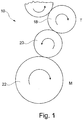
- Fig. 1 shows schematically a view of a filter feed device 10 in detail, the filter feed device 10 being a drum arrangement T, which is part of a filter attachment machine M shown schematically.
- the drum arrangement T is integrated into the filter attachment machine M here.
- Filter rods are removed from a magazine with filter rods (not shown here) by means of a removal drum and cut into several filter plugs using cutting knives.
- the filter plugs are then arranged on a staggered drum 18, the filter stoppers being arranged on the staggered drum 18 in the receiving troughs, offset longitudinally and axially and transversely to one another.
- the staggered filter plugs are then transferred from the staggered drum 18 to a push drum 20 so that the filter plugs are shifted longitudinally and axially in the receiving troughs of the push drum 20 against a lateral stop.
- the filter rods arranged in a row transversely axially one behind the other are then transferred from the pusher drum 20 to a subsequent transport drum 22.
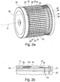
- Fig. 2a is schematically shown a perspective view of a sliding drum 20 according to the invention according to a first embodiment.
- the sliding drum 20 has receiving troughs 30 arranged one behind the other in the circumferential direction, in which the filter plugs are arranged in a staggered manner and offset from one another when they are transferred from the staggered drum.
- Each receiving trough 30 has a trough base 32 on which the rod-shaped articles or filter plugs are arranged.
- the trough base 32 of each receiving trough 30 is delimited by a trough web 34 which leads the pusher drum 20 in the conveying direction and by a trough web 34 following the trough base 32 in the conveying direction.
- the depression base 32 is preferably designed without interruption.
- FIG. 2b is a schematic cross-section through the in Fig. 2a shown Push drum 20 shown in detail.
- a filter plug FS is shown schematically as an example.
- two or more filter plugs or filter segments are arranged in the receiving trough 30 or the receiving troughs 30 next to one another and, preferably simultaneously, are displaced in the longitudinal axial direction.
- the filter plugs FS are arranged in the receiving troughs 30, the trough webs 34 having a trough height H that is greater than the diameter of the filter plugs FS or rod-shaped articles arranged in the receiving troughs 30.
- the (maximum) trough height H of the receiving troughs 30 is measured between the trough bottom 32 and the upper edge of the trough webs 34.
- the trough webs 34 extend in the longitudinal direction and laterally have a stepped trough web area 36 which is less than the height of the trough base 32.
- the recessed trough web areas 36 here have a height that is smaller than the diameter of the filter plugs FS, so that the filter plugs FS or rod-shaped articles protrude between the trough web areas 36.
- the sliding drum 20 shown here is designed in the manner of a step.
- the trough web areas 36 are laterally bounded at the edge by a stop 42, so that the filter plugs FS are displaced against the stop 42 during the transverse axial conveyance on the sliding drum 20 and after their longitudinally axial displacement in the receiving troughs 30.
- the stop 42 can be arranged in a stationary manner on the sliding drum 20, since it is positioned higher than the trough web region 36 in the radial direction.
- the sliding drum 20 has a suction bore 44, so that after the filter plugs FS have been placed against the stop 42, the filter plugs FS are subjected to negative pressure and held in the receiving troughs 30 until they are released to the following conveyor drum.
- a section of a sliding drum 20 according to a further embodiment is shown in a perspective view.
- the sliding drum 20 has trough webs 34 which have a trough-like or U-shaped recessed, ie, trough web region 36 which is stepped in height.
- a bevel 38 is provided on the region of the trough web regions 36 facing the stop 42.
- FIG. 3b A further exemplary embodiment of a sliding drum 20 according to the invention is shown in detail, with stops of different lengths on the receiving troughs 30 being arranged laterally on the trough web regions 36.
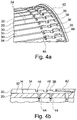
- FIGs 4a and 4b different views of a sliding drum 20 according to a further embodiment are shown.
- the trough web areas 36 of the trough webs 34 are crenellated, preferably in the form of rectangular crenellations.
- the higher shoulders of the crenellated trough web regions 36 have a height between 50% to 80% of the trough height H, in particular 65% to 75% of the trough size H.
- the rectangular recesses of the crenellated trough web regions 36 which are set back radially further inward, preferably have a height between 20% to 45% of the trough height H, in particular between 35% to 45% of the trough height H.
- the edge regions of the trough web regions 36 are designed with bevels 46.
Landscapes
- Engineering & Computer Science (AREA)
- Mechanical Engineering (AREA)
- Cigarettes, Filters, And Manufacturing Of Filters (AREA)
- Manufacturing Of Cigar And Cigarette Tobacco (AREA)
- Specific Conveyance Elements (AREA)
Priority Applications (1)
| Application Number | Priority Date | Filing Date | Title |
|---|---|---|---|
| PL19160191T PL3536172T3 (pl) | 2018-03-05 | 2019-03-01 | Bęben przesuwający przemysłu przetwórstwa tytoniu |
Applications Claiming Priority (1)
| Application Number | Priority Date | Filing Date | Title |
|---|---|---|---|
| DE102018104957.9A DE102018104957A1 (de) | 2018-03-05 | 2018-03-05 | Schiebetrommel der Tabak verarbeitenden Industrie |
Publications (3)
| Publication Number | Publication Date |
|---|---|
| EP3536172A2 EP3536172A2 (de) | 2019-09-11 |
| EP3536172A3 EP3536172A3 (de) | 2019-09-25 |
| EP3536172B1 true EP3536172B1 (de) | 2020-08-19 |
Family
ID=65657320
Family Applications (1)
| Application Number | Title | Priority Date | Filing Date |
|---|---|---|---|
| EP19160191.3A Active EP3536172B1 (de) | 2018-03-05 | 2019-03-01 | Schiebetrommel der tabak verarbeitenden industrie |
Country Status (4)
| Country | Link |
|---|---|
| EP (1) | EP3536172B1 (pl) |
| CN (1) | CN110228702B (pl) |
| DE (1) | DE102018104957A1 (pl) |
| PL (1) | PL3536172T3 (pl) |
Families Citing this family (5)
| Publication number | Priority date | Publication date | Assignee | Title |
|---|---|---|---|---|
| DE102020100437A1 (de) * | 2020-01-10 | 2021-07-15 | Hauni Maschinenbau Gmbh | Fördertrommel der Tabak verarbeitenden Industrie |
| EP3909438B1 (en) * | 2020-05-12 | 2024-04-10 | G.D S.p.A. | Transfer unit |
| DE102020120519A1 (de) * | 2020-08-04 | 2022-02-10 | Hauni Maschinenbau Gmbh | Schiebetrommel der Tabak verarbeitenden Industrie |
| DE102021121351A1 (de) * | 2021-08-17 | 2023-02-23 | Körber Technologies Gmbh | Fördertrommel der Tabak verarbeitenden Industrie |
| CN118239244B (zh) * | 2024-05-24 | 2024-08-06 | 江苏易高烟草机械有限公司 | 一种烟草加工行业的输送滚筒 |
Citations (12)
| Publication number | Priority date | Publication date | Assignee | Title |
|---|---|---|---|---|
| DE3321737A1 (de) | 1982-07-03 | 1984-01-05 | Hauni-Werke Körber & Co KG, 2050 Hamburg | Verfahren und vorrichtung zum herstellen von mundstuecklosen plainzigaretten |
| EP0316948A1 (en) | 1987-11-19 | 1989-05-24 | Japan Tobacco Inc. | Apparatus for manufacturing dual filter plugs for cigarettes and method of manufacturing the same |
| EP0679343A2 (en) | 1994-03-31 | 1995-11-02 | Japan Tobacco Inc. | Grading device used in manufacture of filter plugs for cigarettes |
| EP0693257A1 (en) | 1994-07-22 | 1996-01-24 | Japan Tobacco Inc. | Apparatus for receiving rod members |
| EP0966890A1 (en) | 1998-05-27 | 1999-12-29 | Philip Morris Products Inc. | Transfer assembly for tobacco rods |
| WO2005046366A1 (en) | 2003-11-17 | 2005-05-26 | G.D Societa' Per Azioni | Centring drum for filter assembly machines |
| EP2198725A1 (de) | 2008-12-19 | 2010-06-23 | Hauni Maschinbau AG | Taumelscheibe, Fördertrommel und Maschine der Tabak verarbeitenden Industrie |
| EP2335503A1 (de) | 2009-12-16 | 2011-06-22 | HAUNI Maschinenbau AG | Multisegmentfilterherstellung der Tabak verarbeitenden Industrie |
| DE102013210634A1 (de) | 2013-06-07 | 2014-12-11 | Hauni Maschinenbau Ag | Schiebetrommel für eine Maschine der Tabak verarbeitenden Industrie |
| EP3141134A2 (de) | 2015-08-20 | 2017-03-15 | Hauni Maschinenbau GmbH | Schiebetrommel der tabak verarbeitenden industrie |
| WO2017203258A1 (en) | 2016-05-27 | 2017-11-30 | British American Tobacco (Investments) Limited | Apparatus and method for manufacturing tobacco industry products |
| WO2018096518A1 (en) | 2016-11-28 | 2018-05-31 | G.D S.P.A. | Method and drum for moving rod-shaped articles of the tobacco industry |
Family Cites Families (4)
| Publication number | Priority date | Publication date | Assignee | Title |
|---|---|---|---|---|
| GB9210681D0 (en) | 1992-05-19 | 1992-07-01 | Molins Plc | Filter cigarette manufacture |
| DE19858600A1 (de) | 1998-12-18 | 2000-06-21 | Hauni Maschinenbau Ag | Vorrichtung zum längsaxialen Positionieren von zu durchtrennenden stabförmigen Artikeln der tabakverarbeitenden Industrie |
| DE102012209032A1 (de) * | 2012-05-30 | 2013-12-05 | Hauni Maschinenbau Ag | Fördertrommel der Tabak verarbeitenden Industrie |
| DE102013201854A1 (de) * | 2013-02-05 | 2014-08-07 | Hauni Maschinenbau Ag | Förderung von stabförmigen Artikeln der Tabak verarbeitenden Industrie mit druckempfindlichen Objekten |
-
2018
- 2018-03-05 DE DE102018104957.9A patent/DE102018104957A1/de active Pending
-
2019
- 2019-03-01 EP EP19160191.3A patent/EP3536172B1/de active Active
- 2019-03-01 PL PL19160191T patent/PL3536172T3/pl unknown
- 2019-03-05 CN CN201910164092.XA patent/CN110228702B/zh active Active
Patent Citations (12)
| Publication number | Priority date | Publication date | Assignee | Title |
|---|---|---|---|---|
| DE3321737A1 (de) | 1982-07-03 | 1984-01-05 | Hauni-Werke Körber & Co KG, 2050 Hamburg | Verfahren und vorrichtung zum herstellen von mundstuecklosen plainzigaretten |
| EP0316948A1 (en) | 1987-11-19 | 1989-05-24 | Japan Tobacco Inc. | Apparatus for manufacturing dual filter plugs for cigarettes and method of manufacturing the same |
| EP0679343A2 (en) | 1994-03-31 | 1995-11-02 | Japan Tobacco Inc. | Grading device used in manufacture of filter plugs for cigarettes |
| EP0693257A1 (en) | 1994-07-22 | 1996-01-24 | Japan Tobacco Inc. | Apparatus for receiving rod members |
| EP0966890A1 (en) | 1998-05-27 | 1999-12-29 | Philip Morris Products Inc. | Transfer assembly for tobacco rods |
| WO2005046366A1 (en) | 2003-11-17 | 2005-05-26 | G.D Societa' Per Azioni | Centring drum for filter assembly machines |
| EP2198725A1 (de) | 2008-12-19 | 2010-06-23 | Hauni Maschinbau AG | Taumelscheibe, Fördertrommel und Maschine der Tabak verarbeitenden Industrie |
| EP2335503A1 (de) | 2009-12-16 | 2011-06-22 | HAUNI Maschinenbau AG | Multisegmentfilterherstellung der Tabak verarbeitenden Industrie |
| DE102013210634A1 (de) | 2013-06-07 | 2014-12-11 | Hauni Maschinenbau Ag | Schiebetrommel für eine Maschine der Tabak verarbeitenden Industrie |
| EP3141134A2 (de) | 2015-08-20 | 2017-03-15 | Hauni Maschinenbau GmbH | Schiebetrommel der tabak verarbeitenden industrie |
| WO2017203258A1 (en) | 2016-05-27 | 2017-11-30 | British American Tobacco (Investments) Limited | Apparatus and method for manufacturing tobacco industry products |
| WO2018096518A1 (en) | 2016-11-28 | 2018-05-31 | G.D S.P.A. | Method and drum for moving rod-shaped articles of the tobacco industry |
Also Published As
| Publication number | Publication date |
|---|---|
| PL3536172T3 (pl) | 2021-01-25 |
| CN110228702B (zh) | 2022-06-24 |
| EP3536172A3 (de) | 2019-09-25 |
| DE102018104957A1 (de) | 2019-09-05 |
| CN110228702A (zh) | 2019-09-13 |
| EP3536172A2 (de) | 2019-09-11 |
Similar Documents
| Publication | Publication Date | Title |
|---|---|---|
| EP3141134B1 (de) | Schiebetrommel der tabak verarbeitenden industrie | |
| EP3536172B1 (de) | Schiebetrommel der tabak verarbeitenden industrie | |
| EP3259999B1 (de) | Förderung von stabförmigen artikeln der tabak verarbeitenden industrie | |
| EP3536173B1 (de) | Fördertrommel der tabak verarbeitenden industrie | |
| EP3298909B1 (de) | Herstellung von rauchartikelprodukten | |
| EP3685684B1 (de) | Herstellung von stabförmigen rauchprodukten | |
| WO2012126588A1 (de) | Herstellung von filterstopfen bzw. von filterzigaretten | |
| EP1374706B1 (de) | Filterzuführung an einer Filteransetzmaschine | |
| DE102017127593A1 (de) | Schiebetrommel der Tabak verarbeitenden Industrie | |
| EP2712509B2 (de) | Fördern von stabförmigen Artikeln der Tabak verarbeitenden Industrie | |
| EP3434117B1 (de) | Herstellung von stabförmigen rauchprodukten | |
| EP3641572B1 (de) | Verfahren zum herstellen von rauchartikelprodukten | |
| EP3281537A2 (de) | Fördertrommel der tabak verarbeitenden industrie | |
| DE102013221115A1 (de) | Schneiden von stabförmigen Artikeln der Tabak verarbeitenden Industrie | |
| DE102013210634A1 (de) | Schiebetrommel für eine Maschine der Tabak verarbeitenden Industrie | |
| EP4266913B1 (de) | Trommelanordnung zum queraxialen fördern von stabförmigen artikeln der tabak verarbeitenden industrie | |
| EP1527703B1 (de) | Staffeltrommel | |
| EP4369955B1 (de) | Fördertrommel der tabak verarbeitenden industrie | |
| EP4069001B1 (de) | Fördertrommel der tabak verarbeitenden industrie | |
| EP2696709B1 (de) | Förderung von stabförmigen artikeln der tabak verarbeitenden industrie | |
| EP2696707B1 (de) | Förderung von stabförmigen artikeln der tabak verarbeitenden industrie | |
| DE102018110468A1 (de) | Entnahmetrommel für eine Maschine der Tabak verarbeitenden Industrie | |
| EP3189740B1 (de) | Verfahren zum herstellen eines multisegmentfilters und multisegmentfilterherstelleinrichtung der tabak verarbeitenden industrie | |
| EP2687112B1 (de) | Staffeln von Filterstabsegmenten | |
| DE102024116975A1 (de) | Trommelanordnung zum queraxialen Fördern von stabförmigen Artikeln der Tabak verarbeitenden Industrie |
Legal Events
| Date | Code | Title | Description |
|---|---|---|---|
| PUAI | Public reference made under article 153(3) epc to a published international application that has entered the european phase |
Free format text: ORIGINAL CODE: 0009012 |
|
| STAA | Information on the status of an ep patent application or granted ep patent |
Free format text: STATUS: THE APPLICATION HAS BEEN PUBLISHED |
|
| PUAL | Search report despatched |
Free format text: ORIGINAL CODE: 0009013 |
|
| AK | Designated contracting states |
Kind code of ref document: A2 Designated state(s): AL AT BE BG CH CY CZ DE DK EE ES FI FR GB GR HR HU IE IS IT LI LT LU LV MC MK MT NL NO PL PT RO RS SE SI SK SM TR |
|
| AX | Request for extension of the european patent |
Extension state: BA ME |
|
| AK | Designated contracting states |
Kind code of ref document: A3 Designated state(s): AL AT BE BG CH CY CZ DE DK EE ES FI FR GB GR HR HU IE IS IT LI LT LU LV MC MK MT NL NO PL PT RO RS SE SI SK SM TR |
|
| AX | Request for extension of the european patent |
Extension state: BA ME |
|
| RIC1 | Information provided on ipc code assigned before grant |
Ipc: A24C 5/32 20060101AFI20190819BHEP |
|
| STAA | Information on the status of an ep patent application or granted ep patent |
Free format text: STATUS: REQUEST FOR EXAMINATION WAS MADE |
|
| 17P | Request for examination filed |
Effective date: 20200226 |
|
| RBV | Designated contracting states (corrected) |
Designated state(s): AL AT BE BG CH CY CZ DE DK EE ES FI FR GB GR HR HU IE IS IT LI LT LU LV MC MK MT NL NO PL PT RO RS SE SI SK SM TR |
|
| GRAP | Despatch of communication of intention to grant a patent |
Free format text: ORIGINAL CODE: EPIDOSNIGR1 |
|
| STAA | Information on the status of an ep patent application or granted ep patent |
Free format text: STATUS: GRANT OF PATENT IS INTENDED |
|
| INTG | Intention to grant announced |
Effective date: 20200526 |
|
| GRAS | Grant fee paid |
Free format text: ORIGINAL CODE: EPIDOSNIGR3 |
|
| GRAA | (expected) grant |
Free format text: ORIGINAL CODE: 0009210 |
|
| STAA | Information on the status of an ep patent application or granted ep patent |
Free format text: STATUS: THE PATENT HAS BEEN GRANTED |
|
| AK | Designated contracting states |
Kind code of ref document: B1 Designated state(s): AL AT BE BG CH CY CZ DE DK EE ES FI FR GB GR HR HU IE IS IT LI LT LU LV MC MK MT NL NO PL PT RO RS SE SI SK SM TR |
|
| REG | Reference to a national code |
Ref country code: CH Ref legal event code: EP |
|
| REG | Reference to a national code |
Ref country code: DE Ref legal event code: R096 Ref document number: 502019000151 Country of ref document: DE |
|
| REG | Reference to a national code |
Ref country code: AT Ref legal event code: REF Ref document number: 1302937 Country of ref document: AT Kind code of ref document: T Effective date: 20200915 |
|
| REG | Reference to a national code |
Ref country code: IE Ref legal event code: FG4D Free format text: LANGUAGE OF EP DOCUMENT: GERMAN |
|
| REG | Reference to a national code |
Ref country code: NL Ref legal event code: FP |
|
| REG | Reference to a national code |
Ref country code: LT Ref legal event code: MG4D |
|
| PG25 | Lapsed in a contracting state [announced via postgrant information from national office to epo] |
Ref country code: SE Free format text: LAPSE BECAUSE OF FAILURE TO SUBMIT A TRANSLATION OF THE DESCRIPTION OR TO PAY THE FEE WITHIN THE PRESCRIBED TIME-LIMIT Effective date: 20200819 Ref country code: NO Free format text: LAPSE BECAUSE OF FAILURE TO SUBMIT A TRANSLATION OF THE DESCRIPTION OR TO PAY THE FEE WITHIN THE PRESCRIBED TIME-LIMIT Effective date: 20201119 Ref country code: HR Free format text: LAPSE BECAUSE OF FAILURE TO SUBMIT A TRANSLATION OF THE DESCRIPTION OR TO PAY THE FEE WITHIN THE PRESCRIBED TIME-LIMIT Effective date: 20200819 Ref country code: PT Free format text: LAPSE BECAUSE OF FAILURE TO SUBMIT A TRANSLATION OF THE DESCRIPTION OR TO PAY THE FEE WITHIN THE PRESCRIBED TIME-LIMIT Effective date: 20201221 Ref country code: GR Free format text: LAPSE BECAUSE OF FAILURE TO SUBMIT A TRANSLATION OF THE DESCRIPTION OR TO PAY THE FEE WITHIN THE PRESCRIBED TIME-LIMIT Effective date: 20201120 Ref country code: LT Free format text: LAPSE BECAUSE OF FAILURE TO SUBMIT A TRANSLATION OF THE DESCRIPTION OR TO PAY THE FEE WITHIN THE PRESCRIBED TIME-LIMIT Effective date: 20200819 Ref country code: BG Free format text: LAPSE BECAUSE OF FAILURE TO SUBMIT A TRANSLATION OF THE DESCRIPTION OR TO PAY THE FEE WITHIN THE PRESCRIBED TIME-LIMIT Effective date: 20201119 Ref country code: FI Free format text: LAPSE BECAUSE OF FAILURE TO SUBMIT A TRANSLATION OF THE DESCRIPTION OR TO PAY THE FEE WITHIN THE PRESCRIBED TIME-LIMIT Effective date: 20200819 |
|
| PG25 | Lapsed in a contracting state [announced via postgrant information from national office to epo] |
Ref country code: LV Free format text: LAPSE BECAUSE OF FAILURE TO SUBMIT A TRANSLATION OF THE DESCRIPTION OR TO PAY THE FEE WITHIN THE PRESCRIBED TIME-LIMIT Effective date: 20200819 Ref country code: RS Free format text: LAPSE BECAUSE OF FAILURE TO SUBMIT A TRANSLATION OF THE DESCRIPTION OR TO PAY THE FEE WITHIN THE PRESCRIBED TIME-LIMIT Effective date: 20200819 Ref country code: IS Free format text: LAPSE BECAUSE OF FAILURE TO SUBMIT A TRANSLATION OF THE DESCRIPTION OR TO PAY THE FEE WITHIN THE PRESCRIBED TIME-LIMIT Effective date: 20201219 |
|
| PG25 | Lapsed in a contracting state [announced via postgrant information from national office to epo] |
Ref country code: RO Free format text: LAPSE BECAUSE OF FAILURE TO SUBMIT A TRANSLATION OF THE DESCRIPTION OR TO PAY THE FEE WITHIN THE PRESCRIBED TIME-LIMIT Effective date: 20200819 Ref country code: CZ Free format text: LAPSE BECAUSE OF FAILURE TO SUBMIT A TRANSLATION OF THE DESCRIPTION OR TO PAY THE FEE WITHIN THE PRESCRIBED TIME-LIMIT Effective date: 20200819 Ref country code: DK Free format text: LAPSE BECAUSE OF FAILURE TO SUBMIT A TRANSLATION OF THE DESCRIPTION OR TO PAY THE FEE WITHIN THE PRESCRIBED TIME-LIMIT Effective date: 20200819 Ref country code: EE Free format text: LAPSE BECAUSE OF FAILURE TO SUBMIT A TRANSLATION OF THE DESCRIPTION OR TO PAY THE FEE WITHIN THE PRESCRIBED TIME-LIMIT Effective date: 20200819 Ref country code: SM Free format text: LAPSE BECAUSE OF FAILURE TO SUBMIT A TRANSLATION OF THE DESCRIPTION OR TO PAY THE FEE WITHIN THE PRESCRIBED TIME-LIMIT Effective date: 20200819 |
|
| REG | Reference to a national code |
Ref country code: DE Ref legal event code: R026 Ref document number: 502019000151 Country of ref document: DE |
|
| PLBI | Opposition filed |
Free format text: ORIGINAL CODE: 0009260 |
|
| PG25 | Lapsed in a contracting state [announced via postgrant information from national office to epo] |
Ref country code: ES Free format text: LAPSE BECAUSE OF FAILURE TO SUBMIT A TRANSLATION OF THE DESCRIPTION OR TO PAY THE FEE WITHIN THE PRESCRIBED TIME-LIMIT Effective date: 20200819 Ref country code: AL Free format text: LAPSE BECAUSE OF FAILURE TO SUBMIT A TRANSLATION OF THE DESCRIPTION OR TO PAY THE FEE WITHIN THE PRESCRIBED TIME-LIMIT Effective date: 20200819 |
|
| PLAX | Notice of opposition and request to file observation + time limit sent |
Free format text: ORIGINAL CODE: EPIDOSNOBS2 |
|
| 26 | Opposition filed |
Opponent name: G.D S.P.A. Effective date: 20210506 |
|
| PG25 | Lapsed in a contracting state [announced via postgrant information from national office to epo] |
Ref country code: SK Free format text: LAPSE BECAUSE OF FAILURE TO SUBMIT A TRANSLATION OF THE DESCRIPTION OR TO PAY THE FEE WITHIN THE PRESCRIBED TIME-LIMIT Effective date: 20200819 |
|
| PG25 | Lapsed in a contracting state [announced via postgrant information from national office to epo] |
Ref country code: SI Free format text: LAPSE BECAUSE OF FAILURE TO SUBMIT A TRANSLATION OF THE DESCRIPTION OR TO PAY THE FEE WITHIN THE PRESCRIBED TIME-LIMIT Effective date: 20200819 |
|
| PLBB | Reply of patent proprietor to notice(s) of opposition received |
Free format text: ORIGINAL CODE: EPIDOSNOBS3 |
|
| PG25 | Lapsed in a contracting state [announced via postgrant information from national office to epo] |
Ref country code: MC Free format text: LAPSE BECAUSE OF FAILURE TO SUBMIT A TRANSLATION OF THE DESCRIPTION OR TO PAY THE FEE WITHIN THE PRESCRIBED TIME-LIMIT Effective date: 20200819 |
|
| REG | Reference to a national code |
Ref country code: BE Ref legal event code: MM Effective date: 20210331 |
|
| PG25 | Lapsed in a contracting state [announced via postgrant information from national office to epo] |
Ref country code: FR Free format text: LAPSE BECAUSE OF NON-PAYMENT OF DUE FEES Effective date: 20210331 Ref country code: IE Free format text: LAPSE BECAUSE OF NON-PAYMENT OF DUE FEES Effective date: 20210301 Ref country code: LU Free format text: LAPSE BECAUSE OF NON-PAYMENT OF DUE FEES Effective date: 20210301 |
|
| PG25 | Lapsed in a contracting state [announced via postgrant information from national office to epo] |
Ref country code: BE Free format text: LAPSE BECAUSE OF NON-PAYMENT OF DUE FEES Effective date: 20210331 |
|
| REG | Reference to a national code |
Ref country code: DE Ref legal event code: R081 Ref document number: 502019000151 Country of ref document: DE Owner name: KOERBER TECHNOLOGIES GMBH, DE Free format text: FORMER OWNER: HAUNI MASCHINENBAU GMBH, 21033 HAMBURG, DE |
|
| REG | Reference to a national code |
Ref country code: CH Ref legal event code: PL |
|
| REG | Reference to a national code |
Ref country code: NL Ref legal event code: HC Owner name: KOERBER TECHNOLOGIES GMBH; DE Free format text: DETAILS ASSIGNMENT: CHANGE OF OWNER(S), CHANGE OF OWNER(S) NAME; FORMER OWNER NAME: HAUNI MASCHINENBAU GMBH Effective date: 20221025 |
|
| RAP4 | Party data changed (patent owner data changed or rights of a patent transferred) |
Owner name: KOERBER TECHNOLOGIES GMBH |
|
| PG25 | Lapsed in a contracting state [announced via postgrant information from national office to epo] |
Ref country code: LI Free format text: LAPSE BECAUSE OF NON-PAYMENT OF DUE FEES Effective date: 20220331 Ref country code: CH Free format text: LAPSE BECAUSE OF NON-PAYMENT OF DUE FEES Effective date: 20220331 |
|
| PG25 | Lapsed in a contracting state [announced via postgrant information from national office to epo] |
Ref country code: CY Free format text: LAPSE BECAUSE OF FAILURE TO SUBMIT A TRANSLATION OF THE DESCRIPTION OR TO PAY THE FEE WITHIN THE PRESCRIBED TIME-LIMIT Effective date: 20200819 |
|
| P01 | Opt-out of the competence of the unified patent court (upc) registered |
Effective date: 20230616 |
|
| PG25 | Lapsed in a contracting state [announced via postgrant information from national office to epo] |
Ref country code: HU Free format text: LAPSE BECAUSE OF FAILURE TO SUBMIT A TRANSLATION OF THE DESCRIPTION OR TO PAY THE FEE WITHIN THE PRESCRIBED TIME-LIMIT; INVALID AB INITIO Effective date: 20190301 |
|
| GBPC | Gb: european patent ceased through non-payment of renewal fee |
Effective date: 20230301 |
|
| PG25 | Lapsed in a contracting state [announced via postgrant information from national office to epo] |
Ref country code: GB Free format text: LAPSE BECAUSE OF NON-PAYMENT OF DUE FEES Effective date: 20230301 |
|
| PG25 | Lapsed in a contracting state [announced via postgrant information from national office to epo] |
Ref country code: GB Free format text: LAPSE BECAUSE OF NON-PAYMENT OF DUE FEES Effective date: 20230301 |
|
| PG25 | Lapsed in a contracting state [announced via postgrant information from national office to epo] |
Ref country code: MK Free format text: LAPSE BECAUSE OF FAILURE TO SUBMIT A TRANSLATION OF THE DESCRIPTION OR TO PAY THE FEE WITHIN THE PRESCRIBED TIME-LIMIT Effective date: 20200819 |
|
| APBP | Date of receipt of notice of appeal recorded |
Free format text: ORIGINAL CODE: EPIDOSNNOA2O |
|
| APAH | Appeal reference modified |
Free format text: ORIGINAL CODE: EPIDOSCREFNO |
|
| APBM | Appeal reference recorded |
Free format text: ORIGINAL CODE: EPIDOSNREFNO |
|
| APBP | Date of receipt of notice of appeal recorded |
Free format text: ORIGINAL CODE: EPIDOSNNOA2O |
|
| APBQ | Date of receipt of statement of grounds of appeal recorded |
Free format text: ORIGINAL CODE: EPIDOSNNOA3O |
|
| APBQ | Date of receipt of statement of grounds of appeal recorded |
Free format text: ORIGINAL CODE: EPIDOSNNOA3O |
|
| PG25 | Lapsed in a contracting state [announced via postgrant information from national office to epo] |
Ref country code: MT Free format text: LAPSE BECAUSE OF FAILURE TO SUBMIT A TRANSLATION OF THE DESCRIPTION OR TO PAY THE FEE WITHIN THE PRESCRIBED TIME-LIMIT Effective date: 20200819 |
|
| APAH | Appeal reference modified |
Free format text: ORIGINAL CODE: EPIDOSCREFNO |
|
| PGFP | Annual fee paid to national office [announced via postgrant information from national office to epo] |
Ref country code: DE Payment date: 20250331 Year of fee payment: 7 |
|
| REG | Reference to a national code |
Ref country code: AT Ref legal event code: MM01 Ref document number: 1302937 Country of ref document: AT Kind code of ref document: T Effective date: 20240301 |
|
| APAH | Appeal reference modified |
Free format text: ORIGINAL CODE: EPIDOSCREFNO |
|
| PGFP | Annual fee paid to national office [announced via postgrant information from national office to epo] |
Ref country code: IT Payment date: 20250327 Year of fee payment: 7 |
|
| PG25 | Lapsed in a contracting state [announced via postgrant information from national office to epo] |
Ref country code: AT Free format text: LAPSE BECAUSE OF NON-PAYMENT OF DUE FEES Effective date: 20240301 |
|
| PG25 | Lapsed in a contracting state [announced via postgrant information from national office to epo] |
Ref country code: TR Free format text: LAPSE BECAUSE OF FAILURE TO SUBMIT A TRANSLATION OF THE DESCRIPTION OR TO PAY THE FEE WITHIN THE PRESCRIBED TIME-LIMIT Effective date: 20200819 |
|
| APBU | Appeal procedure closed |
Free format text: ORIGINAL CODE: EPIDOSNNOA9O |
|
| PGFP | Annual fee paid to national office [announced via postgrant information from national office to epo] |
Ref country code: AT Payment date: 20260410 Year of fee payment: 5 |
|
| PGFP | Annual fee paid to national office [announced via postgrant information from national office to epo] |
Ref country code: NL Payment date: 20260330 Year of fee payment: 8 |
|
| PGFP | Annual fee paid to national office [announced via postgrant information from national office to epo] |
Ref country code: PL Payment date: 20260220 Year of fee payment: 8 |