EP3535121B1 - Verfahren zur herstellung einer verbundscheibe mit funktionselement - Google Patents
Verfahren zur herstellung einer verbundscheibe mit funktionselement Download PDFInfo
- Publication number
- EP3535121B1 EP3535121B1 EP17787384.1A EP17787384A EP3535121B1 EP 3535121 B1 EP3535121 B1 EP 3535121B1 EP 17787384 A EP17787384 A EP 17787384A EP 3535121 B1 EP3535121 B1 EP 3535121B1
- Authority
- EP
- European Patent Office
- Prior art keywords
- film
- functional element
- thermoplastic
- thickness
- frame
- Prior art date
- Legal status (The legal status is an assumption and is not a legal conclusion. Google has not performed a legal analysis and makes no representation as to the accuracy of the status listed.)
- Active
Links
Images


Classifications
-
- B—PERFORMING OPERATIONS; TRANSPORTING
- B32—LAYERED PRODUCTS
- B32B—LAYERED PRODUCTS, i.e. PRODUCTS BUILT-UP OF STRATA OF FLAT OR NON-FLAT, e.g. CELLULAR OR HONEYCOMB, FORM
- B32B17/00—Layered products essentially comprising sheet glass, or glass, slag, or like fibres
- B32B17/06—Layered products essentially comprising sheet glass, or glass, slag, or like fibres comprising glass as the main or only constituent of a layer, next to another layer of a specific material
- B32B17/10—Layered products essentially comprising sheet glass, or glass, slag, or like fibres comprising glass as the main or only constituent of a layer, next to another layer of a specific material of synthetic resin
-
- B—PERFORMING OPERATIONS; TRANSPORTING
- B32—LAYERED PRODUCTS
- B32B—LAYERED PRODUCTS, i.e. PRODUCTS BUILT-UP OF STRATA OF FLAT OR NON-FLAT, e.g. CELLULAR OR HONEYCOMB, FORM
- B32B17/00—Layered products essentially comprising sheet glass, or glass, slag, or like fibres
- B32B17/06—Layered products essentially comprising sheet glass, or glass, slag, or like fibres comprising glass as the main or only constituent of a layer, next to another layer of a specific material
- B32B17/10—Layered products essentially comprising sheet glass, or glass, slag, or like fibres comprising glass as the main or only constituent of a layer, next to another layer of a specific material of synthetic resin
- B32B17/10005—Layered products essentially comprising sheet glass, or glass, slag, or like fibres comprising glass as the main or only constituent of a layer, next to another layer of a specific material of synthetic resin laminated safety glass or glazing
- B32B17/1055—Layered products essentially comprising sheet glass, or glass, slag, or like fibres comprising glass as the main or only constituent of a layer, next to another layer of a specific material of synthetic resin laminated safety glass or glazing characterized by the resin layer, i.e. interlayer
- B32B17/10761—Layered products essentially comprising sheet glass, or glass, slag, or like fibres comprising glass as the main or only constituent of a layer, next to another layer of a specific material of synthetic resin laminated safety glass or glazing characterized by the resin layer, i.e. interlayer containing vinyl acetal
-
- B—PERFORMING OPERATIONS; TRANSPORTING
- B32—LAYERED PRODUCTS
- B32B—LAYERED PRODUCTS, i.e. PRODUCTS BUILT-UP OF STRATA OF FLAT OR NON-FLAT, e.g. CELLULAR OR HONEYCOMB, FORM
- B32B17/00—Layered products essentially comprising sheet glass, or glass, slag, or like fibres
- B32B17/06—Layered products essentially comprising sheet glass, or glass, slag, or like fibres comprising glass as the main or only constituent of a layer, next to another layer of a specific material
- B32B17/10—Layered products essentially comprising sheet glass, or glass, slag, or like fibres comprising glass as the main or only constituent of a layer, next to another layer of a specific material of synthetic resin
- B32B17/10005—Layered products essentially comprising sheet glass, or glass, slag, or like fibres comprising glass as the main or only constituent of a layer, next to another layer of a specific material of synthetic resin laminated safety glass or glazing
- B32B17/10009—Layered products essentially comprising sheet glass, or glass, slag, or like fibres comprising glass as the main or only constituent of a layer, next to another layer of a specific material of synthetic resin laminated safety glass or glazing characterized by the number, the constitution or treatment of glass sheets
- B32B17/10036—Layered products essentially comprising sheet glass, or glass, slag, or like fibres comprising glass as the main or only constituent of a layer, next to another layer of a specific material of synthetic resin laminated safety glass or glazing characterized by the number, the constitution or treatment of glass sheets comprising two outer glass sheets
-
- B—PERFORMING OPERATIONS; TRANSPORTING
- B32—LAYERED PRODUCTS
- B32B—LAYERED PRODUCTS, i.e. PRODUCTS BUILT-UP OF STRATA OF FLAT OR NON-FLAT, e.g. CELLULAR OR HONEYCOMB, FORM
- B32B17/00—Layered products essentially comprising sheet glass, or glass, slag, or like fibres
- B32B17/06—Layered products essentially comprising sheet glass, or glass, slag, or like fibres comprising glass as the main or only constituent of a layer, next to another layer of a specific material
- B32B17/10—Layered products essentially comprising sheet glass, or glass, slag, or like fibres comprising glass as the main or only constituent of a layer, next to another layer of a specific material of synthetic resin
- B32B17/10005—Layered products essentially comprising sheet glass, or glass, slag, or like fibres comprising glass as the main or only constituent of a layer, next to another layer of a specific material of synthetic resin laminated safety glass or glazing
- B32B17/10165—Functional features of the laminated safety glass or glazing
- B32B17/10293—Edge features, e.g. inserts or holes
-
- B—PERFORMING OPERATIONS; TRANSPORTING
- B32—LAYERED PRODUCTS
- B32B—LAYERED PRODUCTS, i.e. PRODUCTS BUILT-UP OF STRATA OF FLAT OR NON-FLAT, e.g. CELLULAR OR HONEYCOMB, FORM
- B32B17/00—Layered products essentially comprising sheet glass, or glass, slag, or like fibres
- B32B17/06—Layered products essentially comprising sheet glass, or glass, slag, or like fibres comprising glass as the main or only constituent of a layer, next to another layer of a specific material
- B32B17/10—Layered products essentially comprising sheet glass, or glass, slag, or like fibres comprising glass as the main or only constituent of a layer, next to another layer of a specific material of synthetic resin
- B32B17/10005—Layered products essentially comprising sheet glass, or glass, slag, or like fibres comprising glass as the main or only constituent of a layer, next to another layer of a specific material of synthetic resin laminated safety glass or glazing
- B32B17/1055—Layered products essentially comprising sheet glass, or glass, slag, or like fibres comprising glass as the main or only constituent of a layer, next to another layer of a specific material of synthetic resin laminated safety glass or glazing characterized by the resin layer, i.e. interlayer
- B32B17/10559—Shape of the cross-section
-
- B—PERFORMING OPERATIONS; TRANSPORTING
- B32—LAYERED PRODUCTS
- B32B—LAYERED PRODUCTS, i.e. PRODUCTS BUILT-UP OF STRATA OF FLAT OR NON-FLAT, e.g. CELLULAR OR HONEYCOMB, FORM
- B32B17/00—Layered products essentially comprising sheet glass, or glass, slag, or like fibres
- B32B17/06—Layered products essentially comprising sheet glass, or glass, slag, or like fibres comprising glass as the main or only constituent of a layer, next to another layer of a specific material
- B32B17/10—Layered products essentially comprising sheet glass, or glass, slag, or like fibres comprising glass as the main or only constituent of a layer, next to another layer of a specific material of synthetic resin
- B32B17/10005—Layered products essentially comprising sheet glass, or glass, slag, or like fibres comprising glass as the main or only constituent of a layer, next to another layer of a specific material of synthetic resin laminated safety glass or glazing
- B32B17/1055—Layered products essentially comprising sheet glass, or glass, slag, or like fibres comprising glass as the main or only constituent of a layer, next to another layer of a specific material of synthetic resin laminated safety glass or glazing characterized by the resin layer, i.e. interlayer
- B32B17/10559—Shape of the cross-section
- B32B17/10568—Shape of the cross-section varying in thickness
-
- B—PERFORMING OPERATIONS; TRANSPORTING
- B32—LAYERED PRODUCTS
- B32B—LAYERED PRODUCTS, i.e. PRODUCTS BUILT-UP OF STRATA OF FLAT OR NON-FLAT, e.g. CELLULAR OR HONEYCOMB, FORM
- B32B17/00—Layered products essentially comprising sheet glass, or glass, slag, or like fibres
- B32B17/06—Layered products essentially comprising sheet glass, or glass, slag, or like fibres comprising glass as the main or only constituent of a layer, next to another layer of a specific material
- B32B17/10—Layered products essentially comprising sheet glass, or glass, slag, or like fibres comprising glass as the main or only constituent of a layer, next to another layer of a specific material of synthetic resin
- B32B17/10005—Layered products essentially comprising sheet glass, or glass, slag, or like fibres comprising glass as the main or only constituent of a layer, next to another layer of a specific material of synthetic resin laminated safety glass or glazing
- B32B17/1055—Layered products essentially comprising sheet glass, or glass, slag, or like fibres comprising glass as the main or only constituent of a layer, next to another layer of a specific material of synthetic resin laminated safety glass or glazing characterized by the resin layer, i.e. interlayer
- B32B17/1077—Layered products essentially comprising sheet glass, or glass, slag, or like fibres comprising glass as the main or only constituent of a layer, next to another layer of a specific material of synthetic resin laminated safety glass or glazing characterized by the resin layer, i.e. interlayer containing polyurethane
-
- B—PERFORMING OPERATIONS; TRANSPORTING
- B32—LAYERED PRODUCTS
- B32B—LAYERED PRODUCTS, i.e. PRODUCTS BUILT-UP OF STRATA OF FLAT OR NON-FLAT, e.g. CELLULAR OR HONEYCOMB, FORM
- B32B17/00—Layered products essentially comprising sheet glass, or glass, slag, or like fibres
- B32B17/06—Layered products essentially comprising sheet glass, or glass, slag, or like fibres comprising glass as the main or only constituent of a layer, next to another layer of a specific material
- B32B17/10—Layered products essentially comprising sheet glass, or glass, slag, or like fibres comprising glass as the main or only constituent of a layer, next to another layer of a specific material of synthetic resin
- B32B17/10005—Layered products essentially comprising sheet glass, or glass, slag, or like fibres comprising glass as the main or only constituent of a layer, next to another layer of a specific material of synthetic resin laminated safety glass or glazing
- B32B17/1055—Layered products essentially comprising sheet glass, or glass, slag, or like fibres comprising glass as the main or only constituent of a layer, next to another layer of a specific material of synthetic resin laminated safety glass or glazing characterized by the resin layer, i.e. interlayer
- B32B17/10788—Layered products essentially comprising sheet glass, or glass, slag, or like fibres comprising glass as the main or only constituent of a layer, next to another layer of a specific material of synthetic resin laminated safety glass or glazing characterized by the resin layer, i.e. interlayer containing ethylene vinylacetate
-
- B—PERFORMING OPERATIONS; TRANSPORTING
- B32—LAYERED PRODUCTS
- B32B—LAYERED PRODUCTS, i.e. PRODUCTS BUILT-UP OF STRATA OF FLAT OR NON-FLAT, e.g. CELLULAR OR HONEYCOMB, FORM
- B32B37/00—Methods or apparatus for laminating, e.g. by curing or by ultrasonic bonding
- B32B37/12—Methods or apparatus for laminating, e.g. by curing or by ultrasonic bonding characterised by using adhesives
-
- B—PERFORMING OPERATIONS; TRANSPORTING
- B32—LAYERED PRODUCTS
- B32B—LAYERED PRODUCTS, i.e. PRODUCTS BUILT-UP OF STRATA OF FLAT OR NON-FLAT, e.g. CELLULAR OR HONEYCOMB, FORM
- B32B7/00—Layered products characterised by the relation between layers; Layered products characterised by the relative orientation of features between layers, or by the relative values of a measurable parameter between layers, i.e. products comprising layers having different physical, chemical or physicochemical properties; Layered products characterised by the interconnection of layers
- B32B7/04—Interconnection of layers
- B32B7/12—Interconnection of layers using interposed adhesives or interposed materials with bonding properties
-
- B—PERFORMING OPERATIONS; TRANSPORTING
- B60—VEHICLES IN GENERAL
- B60J—WINDOWS, WINDSCREENS, NON-FIXED ROOFS, DOORS, OR SIMILAR DEVICES FOR VEHICLES; REMOVABLE EXTERNAL PROTECTIVE COVERINGS SPECIALLY ADAPTED FOR VEHICLES
- B60J1/00—Windows; Windscreens; Accessories therefor
-
- G—PHYSICS
- G02—OPTICS
- G02F—OPTICAL DEVICES OR ARRANGEMENTS FOR THE CONTROL OF LIGHT BY MODIFICATION OF THE OPTICAL PROPERTIES OF THE MEDIA OF THE ELEMENTS INVOLVED THEREIN; NON-LINEAR OPTICS; FREQUENCY-CHANGING OF LIGHT; OPTICAL LOGIC ELEMENTS; OPTICAL ANALOGUE/DIGITAL CONVERTERS
- G02F1/00—Devices or arrangements for the control of the intensity, colour, phase, polarisation or direction of light arriving from an independent light source, e.g. switching, gating or modulating; Non-linear optics
- G02F1/01—Devices or arrangements for the control of the intensity, colour, phase, polarisation or direction of light arriving from an independent light source, e.g. switching, gating or modulating; Non-linear optics for the control of the intensity, phase, polarisation or colour
- G02F1/0102—Constructional details, not otherwise provided for in this subclass
-
- H—ELECTRICITY
- H10—SEMICONDUCTOR DEVICES; ELECTRIC SOLID-STATE DEVICES NOT OTHERWISE PROVIDED FOR
- H10K—ORGANIC ELECTRIC SOLID-STATE DEVICES
- H10K50/00—Organic light-emitting devices
- H10K50/80—Constructional details
- H10K50/84—Passivation; Containers; Encapsulations
-
- B—PERFORMING OPERATIONS; TRANSPORTING
- B29—WORKING OF PLASTICS; WORKING OF SUBSTANCES IN A PLASTIC STATE IN GENERAL
- B29C—SHAPING OR JOINING OF PLASTICS; SHAPING OF MATERIAL IN A PLASTIC STATE, NOT OTHERWISE PROVIDED FOR; AFTER-TREATMENT OF THE SHAPED PRODUCTS, e.g. REPAIRING
- B29C65/00—Joining or sealing of preformed parts, e.g. welding of plastics materials; Apparatus therefor
- B29C65/02—Joining or sealing of preformed parts, e.g. welding of plastics materials; Apparatus therefor by heating, with or without pressure
-
- B—PERFORMING OPERATIONS; TRANSPORTING
- B29—WORKING OF PLASTICS; WORKING OF SUBSTANCES IN A PLASTIC STATE IN GENERAL
- B29C—SHAPING OR JOINING OF PLASTICS; SHAPING OF MATERIAL IN A PLASTIC STATE, NOT OTHERWISE PROVIDED FOR; AFTER-TREATMENT OF THE SHAPED PRODUCTS, e.g. REPAIRING
- B29C65/00—Joining or sealing of preformed parts, e.g. welding of plastics materials; Apparatus therefor
- B29C65/48—Joining or sealing of preformed parts, e.g. welding of plastics materials; Apparatus therefor using adhesives, i.e. using supplementary joining material; solvent bonding
- B29C65/4805—Joining or sealing of preformed parts, e.g. welding of plastics materials; Apparatus therefor using adhesives, i.e. using supplementary joining material; solvent bonding characterised by the type of adhesives
- B29C65/481—Non-reactive adhesives, e.g. physically hardening adhesives
- B29C65/4815—Hot melt adhesives, e.g. thermoplastic adhesives
-
- B—PERFORMING OPERATIONS; TRANSPORTING
- B29—WORKING OF PLASTICS; WORKING OF SUBSTANCES IN A PLASTIC STATE IN GENERAL
- B29C—SHAPING OR JOINING OF PLASTICS; SHAPING OF MATERIAL IN A PLASTIC STATE, NOT OTHERWISE PROVIDED FOR; AFTER-TREATMENT OF THE SHAPED PRODUCTS, e.g. REPAIRING
- B29C65/00—Joining or sealing of preformed parts, e.g. welding of plastics materials; Apparatus therefor
- B29C65/48—Joining or sealing of preformed parts, e.g. welding of plastics materials; Apparatus therefor using adhesives, i.e. using supplementary joining material; solvent bonding
- B29C65/486—Joining or sealing of preformed parts, e.g. welding of plastics materials; Apparatus therefor using adhesives, i.e. using supplementary joining material; solvent bonding characterised by their physical form being non-liquid, e.g. in the form of granules or powders
-
- B—PERFORMING OPERATIONS; TRANSPORTING
- B29—WORKING OF PLASTICS; WORKING OF SUBSTANCES IN A PLASTIC STATE IN GENERAL
- B29C—SHAPING OR JOINING OF PLASTICS; SHAPING OF MATERIAL IN A PLASTIC STATE, NOT OTHERWISE PROVIDED FOR; AFTER-TREATMENT OF THE SHAPED PRODUCTS, e.g. REPAIRING
- B29C66/00—General aspects of processes or apparatus for joining preformed parts
- B29C66/70—General aspects of processes or apparatus for joining preformed parts characterised by the composition, physical properties or the structure of the material of the parts to be joined; Joining with non-plastics material
- B29C66/74—Joining plastics material to non-plastics material
- B29C66/746—Joining plastics material to non-plastics material to inorganic materials not provided for in groups B29C66/742 - B29C66/744
- B29C66/7465—Glass
-
- B—PERFORMING OPERATIONS; TRANSPORTING
- B32—LAYERED PRODUCTS
- B32B—LAYERED PRODUCTS, i.e. PRODUCTS BUILT-UP OF STRATA OF FLAT OR NON-FLAT, e.g. CELLULAR OR HONEYCOMB, FORM
- B32B17/00—Layered products essentially comprising sheet glass, or glass, slag, or like fibres
- B32B17/06—Layered products essentially comprising sheet glass, or glass, slag, or like fibres comprising glass as the main or only constituent of a layer, next to another layer of a specific material
- B32B17/10—Layered products essentially comprising sheet glass, or glass, slag, or like fibres comprising glass as the main or only constituent of a layer, next to another layer of a specific material of synthetic resin
- B32B17/10005—Layered products essentially comprising sheet glass, or glass, slag, or like fibres comprising glass as the main or only constituent of a layer, next to another layer of a specific material of synthetic resin laminated safety glass or glazing
- B32B17/10165—Functional features of the laminated safety glass or glazing
- B32B17/10431—Specific parts for the modulation of light incorporated into the laminated safety glass or glazing
- B32B17/10467—Variable transmission
-
- B—PERFORMING OPERATIONS; TRANSPORTING
- B32—LAYERED PRODUCTS
- B32B—LAYERED PRODUCTS, i.e. PRODUCTS BUILT-UP OF STRATA OF FLAT OR NON-FLAT, e.g. CELLULAR OR HONEYCOMB, FORM
- B32B17/00—Layered products essentially comprising sheet glass, or glass, slag, or like fibres
- B32B17/06—Layered products essentially comprising sheet glass, or glass, slag, or like fibres comprising glass as the main or only constituent of a layer, next to another layer of a specific material
- B32B17/10—Layered products essentially comprising sheet glass, or glass, slag, or like fibres comprising glass as the main or only constituent of a layer, next to another layer of a specific material of synthetic resin
- B32B17/10005—Layered products essentially comprising sheet glass, or glass, slag, or like fibres comprising glass as the main or only constituent of a layer, next to another layer of a specific material of synthetic resin laminated safety glass or glazing
- B32B17/10165—Functional features of the laminated safety glass or glazing
- B32B17/10541—Functional features of the laminated safety glass or glazing comprising a light source or a light guide
-
- B—PERFORMING OPERATIONS; TRANSPORTING
- B32—LAYERED PRODUCTS
- B32B—LAYERED PRODUCTS, i.e. PRODUCTS BUILT-UP OF STRATA OF FLAT OR NON-FLAT, e.g. CELLULAR OR HONEYCOMB, FORM
- B32B2305/00—Condition, form or state of the layers or laminate
- B32B2305/34—Inserts
-
- B—PERFORMING OPERATIONS; TRANSPORTING
- B32—LAYERED PRODUCTS
- B32B—LAYERED PRODUCTS, i.e. PRODUCTS BUILT-UP OF STRATA OF FLAT OR NON-FLAT, e.g. CELLULAR OR HONEYCOMB, FORM
- B32B2605/00—Vehicles
- B32B2605/006—Transparent parts other than made from inorganic glass, e.g. polycarbonate glazings
Definitions
- the invention relates to a method for producing a composite pane with a functional element.
- Glazing in particular composite panes with functional elements, are known whose optical properties are variable.
- the functional elements can often be switched or regulated electrically.
- the optical properties of the functional elements can be changed by applying voltage.
- An example are SPD functional elements ( suspended particle devices ), for example EP 0876608 B1 and WO 2011033313 A1 are known.
- the transmission of visible light can be controlled by the applied voltage. Glazing with such functional elements can be electrically darkened in a convenient way.
- OLED displays organic light emitting diode
- the OLED display can, for example, be used in a motor vehicle windshield to display information for the driver or to replace the rear-view mirror.
- Such solutions are, for example US20110025584A1 or WO2015041106A1 known.
- the functional elements are often provided as prefabricated multi-layer elements that can be easily integrated into laminated glass.
- the functional elements are embedded in a thermoplastic intermediate layer and laminated between two panes of glass.
- the thermoplastic intermediate layer is made from several films, one of which is provided with a recess into which the functional element is inserted with a substantially precise fit.
- Such manufacturing processes are, for example WO2007122429A1 , WO2007122426A1 or WO2014083111A1 known.
- thermoplastic film with the recess and the functional element have a similar thickness. If the thermoplastic film and the functional element are provided by their respective manufacturers with very different thicknesses, an offset occurs, which leads to optical distortions when the layer stack is pressed together during lamination can lead to breakage of the glass pane or damage to the functional element.
- US2005238857A1 discloses a composite pane with an integrated LED functional element. It is proposed to provide the functional element with a polymeric coating in order to ensure the adhesive connection to the adjacent layers and to compensate for any differences in thickness between the functional element and the film of the intermediate layer surrounding it.
- coating the functional element specifically with a polymeric material with the required optical quality and the desired layer thickness is technically complex. Differences in thickness can only be compensated for if the thickness of the functional element is less than the thickness of the surrounding film of the intermediate layer.
- EP 2955164A1 , US2644065A and DE2248094A1 disclose composite panes with integrated functional elements of different types.
- the functional element is not surrounded by a single frame-like film. Instead, the frame around the functional element is formed by two foils of the same thickness, one on top of the other, with a recess. So that no differences in thickness occur, it is necessary that the thickness of the functional element corresponds to approximately twice the film thickness of available standard interlayer films. The method cannot therefore be used with the desired flexibility to compensate for any differences in thickness.
- the object of the present invention is to provide such an improved manufacturing process.
- the method according to the invention includes at least arranging a functional element in a recess of a thermoplastic frame film, arranging the thermoplastic frame film with the functional element between a first glass pane and a second glass pane in a surface-congruent manner to form a layer stack and then connecting the layer stack to form a composite pane lamination.
- the functional element has, in particular, variable optical properties, which can relate, for example, to the degree of light transmittance, the degree of light scattering, the light polarization or the emission of light.
- the recess is preferably designed approximately congruent to the functional element, with a small gap between the recess edge and the functional element of, for example, less than 5 mm, preferably less than 1 mm, being acceptable, so that the recess can also be designed to be slightly larger than the functional element.
- the thermoplastic frame around the functional element can also be formed by several frame films lying congruently one above the other, preferably of the same thickness.
- the recess is understood to be a continuous recess in the frame film, like an extended hole or a passage.
- the recess is often referred to as a cut-out because it is typically made by cutting out an area of the frame film.
- thermoplastic frame film and the functional element have a different thickness. This creates an offset when the functional element is inserted into the recess: the common surface has a step at the transition from the thermoplastic frame film to the functional element. This misalignment can cause problems during later lamination. If the functional element is thicker than the frame film, compressive forces arise on the functional element itself. If the functional element is thinner than the frame film, tensile forces arise after lamination that act axially on the functional element. Both can damage the functional element. In addition, optical distortions can occur or the glass panes can break.
- the offset can also be referred to as a step within the layer stack. It acts as a local change in the total thickness of all components of the layer stack.
- the inventive idea is to at least partially compensate or balance the difference in thickness between the frame film and the functional element by at least one thermoplastic compensating film. This is intended to avoid steps with critical heights.
- the compensation film By using the compensation film, the offset that occurs is reduced.
- the maximum offset is therefore less than the difference in thickness between the frame film and the functional element, which would result as an offset without using the compensation film.
- the maximum offset that occurs corresponds at most to the thickness of the compensation film or is even smaller.
- the expression of at least partial compensation means that the offset does not disappear completely due to the compensation film, but is mitigated.
- the compensation film In order to be able to reduce the offset, the compensation film must have a thickness that is less than twice as large as the difference in thickness, i.e. the height of the offset between the frame film and the functional element. Ideally, the thickness of the compensation film is less than the difference in thickness between the frame film and the functional element.
- the size of the offset depends essentially on the thickness of the compensation film, with the exact relationship depending on the embodiment, as explained below.
- the compensation film there is preferably no offset of greater than 100 ⁇ m in the layer stack.
- no offset of greater than 50 ⁇ m occurs in the layer stack.
- the inventors have found that even with such an offset there is a risk of optical distortions and even glass breakage. Of course, it only makes sense to use a compensating film for this if the difference in thickness between the thermoplastic frame film and the functional element is greater than 50 ⁇ m.
- the compensating film according to the invention differs from the frame film in particular in its thickness, with the compensating film having a significantly smaller thickness than the frame film. This means that any differences in thickness can be flexibly compensated for.
- the thickness of the compensation film is, for example, a maximum of one fifth of the thickness of the frame film.
- the thickness of the frame film can be larger or smaller than the thickness of the functional element.
- the thickness of the thermoplastic frame film is greater than the thickness of the functional element.
- the recess in the frame film is not completely filled by the functional element and an empty space within the recess would remain in the layer stack.
- the thermoplastic compensation film is arranged on the functional element within the recess.
- the compensation film is preferably designed to be essentially congruent with the recess and with the functional element.
- Several compensating films can also be arranged one above the other on the functional element, especially if the difference in thickness is at least 1.5 times or even at least twice the thickness of the compensating film.
- the person skilled in the art will arrange as many compensation foils on the functional element as are necessary, so that either remaining empty space within the recess has a smaller thickness than the compensation film or the topmost compensation film is partially still arranged within the recess and partially protrudes beyond the recess. In both ways, the offset can be reduced compared to the situation without a compensating film.
- the offset can be reduced if the compensation film has a thickness that is less than twice as large as the difference in thickness between the frame film and the functional element. If the thickness of the compensation film is greater than the difference in thickness, the compensation film protrudes beyond the recess in the frame film, but the remaining offset is reduced. Particularly good results are achieved when the thickness of the compensation film is less than the difference in thickness between the frame film and the functional element.
- the first embodiment is therefore summarized as a method for producing a composite pane, at least comprising arranging a functional element in a recess in a thermoplastic frame film, arranging the thermoplastic frame film with the functional element between a first glass pane and a second glass pane to form a layer stack and then connecting the Layer stack to form a composite pane by lamination, wherein the thermoplastic frame film has a greater thickness than the functional element and wherein a compensating film, the thickness of which is less than twice as large as the difference in the thicknesses of the thermoplastic frame film and the functional element, is arranged on the functional element within the recess becomes.
- the thickness of the thermoplastic frame film is smaller than the thickness of the functional element.
- the functional element therefore protrudes beyond the recess.
- the thermoplastic compensation film is arranged on the thermoplastic frame film in a frame-like manner around the recess.
- Frame-like means that the compensation film essentially completely surrounds the recess.
- the frame-like compensation film is preferably arranged approximately flush with the recess.
- a frame-like compensating film is, so to speak, a compensating film which in turn has a recess, the recesses in the frame film and the compensating film preferably being approximately congruent so that they can be arranged flush.
- the compensation film therefore surrounds the protruding part of the functional element.
- the step remaining at the edge of the functional element can also be reduced in the second embodiment.
- an offset would be created on the side edge of the compensating film facing away from the functional element, which corresponds to the thickness of the compensating film.
- those compensating films make sense whose thickness is less than the difference in thickness between the frame film and the functional element.
- the second embodiment is therefore summarized as a method for producing a composite pane, at least comprising arranging a functional element in a recess in a thermoplastic frame film, arranging the thermoplastic frame film with the functional element between a first glass pane and a second glass pane to form a layer stack and then connecting the Layer stack to form a composite pane by lamination, wherein the thermoplastic frame film has a smaller thickness than the functional element and at least one compensating film, the thickness of which is less than the difference in the thicknesses of the thermoplastic frame film and the functional element, is arranged on the thermoplastic frame film in a frame-like manner around the recess .
- the wider the frame-like compensation film the less the glass pane above it is bent during lamination and the more effectively optical distortions and mechanical stresses can be avoided.
- the upper limit is determined by the size of the composite pane, so that the compensation film is designed to be approximately congruent to the frame film.
- compensating films with a smaller width are more cost-effective because material is saved.
- the compensating film therefore preferably does not extend to the side edges of the frame film or the composite pane, and is therefore not designed to be congruent with the frame film, but rather has a smaller area than the frame film.
- the width of the frame-like compensation film is preferably at least 200 times the thickness of the compensation film, preferably at least 500 times.
- the width is preferably at least 10 mm, particularly preferably at least 15 mm.
- the width of the frame-like compensation film is understood to be the distance between the inner boundary edge facing the recess and the outer boundary edge of the compensation film facing away from the recess.
- the difference in thickness between the frame film and the functional element is greater than 1.5 times, in particular greater than twice, the thickness of the compensation film
- several compensation films are arranged one above the other on the frame film and each arranged in a frame-like manner around the recess , whereby the width of the compensation foils decreases as the distance to the frame foil increases.
- the compensating foils are arranged one above the other in a pyramid-like manner, so that each compensating foil creates a step to the compensating foil underneath (or, in the case of the lowest compensating foil, to the frame foil underneath). This effectively prevents the occurrence of large steps and avoids tension during lamination.
- each step of the pyramid-like stack of compensating films is preferably at least 200 times the thickness of the compensating film, preferably at least 500 times.
- the compensating film can be formed in one piece, which is advantageous and therefore preferred in terms of easier handling.
- the compensation film can also be composed of several pieces placed next to each other.
- thermoplastic compensating film can generally be selected by the expert according to the requirements of the individual case.
- a material should be chosen that is suitable for producing an adhesive bond during lamination to the polymeric layers or glass panes (with the exception of the functional element) that are in direct contact with the compensating film, i.e. in particular to the thermoplastic frame film and the glass panes above it or optional further thermoplastic layers , which can be arranged between the glass pane and the frame film.
- the compensation film particularly preferably contains polyvinyl butyral (PVB), ethylene vinyl acetate (EVA) and/or polyurethane (PU), in particular PVB. Since these materials are common for the thermoplastic intermediate layer of composite panes and also create an adhesive connection to glass, a good connection is guaranteed.
- PVB polyvinyl butyral
- EVA ethylene vinyl acetate
- PU polyurethane
- PET polyethylene terephthalate
- thermoplastic compensation film preferably has a thickness of 25 ⁇ m to 100 ⁇ m, particularly preferably 40 ⁇ m to 70 ⁇ m, in particular about 50 ⁇ m. This means that good results can be achieved in terms of reducing mechanical stresses.
- the compensation film therefore preferably has the smallest possible amount of plasticizer in order to be able to make it as thin as possible.
- Common thermoplastic films, especially those made from PVB, have a plasticizer content of at least 15% by weight.
- the compensation film preferably has a reduced value.
- the compensating film preferably contains a plasticizer content of less than 15% by weight, particularly preferably less than 10% by weight, most preferably less than 5% by weight and is in particular essentially free of plasticizer.
- the invention is fundamentally applicable to all functional elements that have a difference in thickness to the frame film.
- the functional element is in particular a functional element with variable optical properties.
- the change in the optical properties can be done passively without the user's influence, such as in the case of a photochromic functional element or a polarizing filter, or actively through the user's influence, for example by changing the electrical voltage applied to the functional element.
- the functional element is preferably a functional element with electrically switchable or controllable optical properties.
- the functional element can be, for example, an SPD, a PDLC or an electrochromic functional element.
- the active layer contains suspended particles, whereby the absorption of light by the active layer can be changed by applying a voltage to the surface electrodes.
- the change in absorption is based on the orientation of the rod-like particles in the electric field when electrical voltage is applied.
- SPD functional elements are off, for example EP 0876608 B1 and WO 2011033313 A1 known.
- the active layer contains liquid crystals that are embedded in a polymer matrix. If no voltage is applied to the surface electrodes, the liquid crystals are aligned disorderly, which leads to strong scattering of the light passing through the active layer. If a voltage is applied to the surface electrodes, the liquid crystals align in a common direction and the transmission of light through the active layer is increased.
- a functional element is, for example DE 102008026339 A1 known.
- the active layer of the functional element is an electrochemically active layer.
- the transmission of visible light depends on the degree of incorporation of ions into the active layer, the ions being provided, for example, by an ion storage layer between the active layer and a surface electrode. The transmission can be influenced by the voltage applied to the surface electrodes, which causes the ions to migrate.
- Suitable functional layers contain, for example, at least tungsten oxide or vanadium oxide.
- Electrochromic functional elements for example, are out WO 2012007334 A1 , US 20120026573 A1 , WO 2010147494 A1 and EP 1862849 A1 known.
- the functional element is an electroluminescent functional element, in particular an OLED display.
- the active layer contains electroluminescent materials, in particular organic electroluminescent materials, whose luminescence is stimulated by applying a voltage.
- Electroluminescent functional elements are available, for example US 2004227462 A1 and WO 2010112789 A2 known.
- the electroluminescent functional element can be used as a simple light source or as a display with which any representation can be shown.
- Such a display can be used, for example, in a windshield to show information to the driver. For example, current speed or other condition parameters can be displayed, or the image from a rear-facing camera can be displayed to replace the rear-view mirror.
- simple surface electrodes that have the same overall potential are not sufficient - rather, the individual pixels must be controlled separately. The measures required for this are known to those skilled in the art and OLED display films are commercially available.
- OLED displays are particularly pressure-sensitive and are also not commercially available with thicknesses that roughly correspond to the thicknesses of common commercially available thermoplastic films. Therefore, the occurrence of offsets in the production of composite panes with OLED displays is particularly likely and at the same time particularly critical. The advantages of the invention therefore unfold in a special way when producing such composite panes, which is why it is preferred.
- the functional element is preferably provided as a multi-layer element.
- the multilayer element contains an active layer which, in the case of electrically switchable or controllable functional elements, is arranged flat between two transparent surface electrodes.
- the active layer provides the switchable or controllable properties, while the switching state can be selected by the voltage applied to the surface electrodes.
- the surface electrodes which can be realized, for example, as thin silver or ITO layers, are electrically connected to an external voltage source in a manner known per se, in particular via suitable connecting cables, for example foil conductors.
- the outer layers of the multilayer element are formed on both sides by insulating, transparent carrier layers, for example polymeric carrier films, usually made of polyethylene terephthalate (PET) with thicknesses of 0.1 mm to 0.5 mm, or very thin glass layers with similar thicknesses.
- the multilayer element therefore contains at least one carrier layer, an active layer and a further carrier layer in the order specified.
- the multilayer element contains, in the order specified, at least one carrier layer, a surface electrode, an active layer, a further surface electrode and a further carrier layer.
- Such multilayer elements are commercially available and can easily be incorporated into the laminated glass.
- the multilayer element can be provided with an edge seal in order to prevent the diffusion of chemical components of the thermoplastic films, for example plasticizers, into the active layer. This reduces the aging of the switchable functional element.
- the edge seal is designed, for example, as a polyimide-containing film or foil, which runs all the way around the side edges of the multilayer element.
- the frame film can be in direct contact with the first and/or second glass pane.
- the frame film with the functional element is connected to each glass pane via a further thermoplastic film.
- the connecting films preferably have no recesses and cover the entire frame film including its recess.
- the lamination of the layer stack to form the composite pane typically takes place under the influence of heat, vacuum and/or pressure.
- Known processes for lamination can be used, for example autoclave processes, vacuum bag processes, vacuum ring processes, calender processes, vacuum laminators or combinations thereof.
- Lamination typically involves deaerating the layer stack, preferably at room temperature, and then melting the thermoplastic film to produce the composite, preferably at temperatures greater than 70 ° C.
- the frame film and the optional connecting films preferably contain PVB, EVA and/or PU, particularly preferably PVB.
- the frame film and the connecting films are preferably made from the same material to ensure an optimal connection.
- the compensation film is preferably based on the same polymer, but may differ from the other films, particularly in terms of the plasticizer content.
- the thickness of the frame film and the optional connecting films is typically from 0.2 mm to 2 mm, preferably from 0.3 mm to 1 mm, for example 0.38 mm or 0.76 mm.
- the first and second glass panes are preferably made of soda lime glass, which is common and inexpensive as window glass. In principle, other types of glass can also be used, such as borosilicate glass, quartz glass, aluminosilicate glass.
- the glass panes can be thermally or chemically toughened.
- the thickness of the glass panes is, for example, from 0.5 mm to 5 mm, preferably from 1 mm to 2.5 mm.
- the glass panes are preferably bent into their final shape before lamination, for example by gravity bending or press bending.
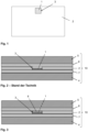
- Fig. 1 shows a top view of a frame film 2.
- the thermoplastic frame film 2 is, for example, a 0.38 mm thick PVB film.
- the frame film has a rectangular recess 3 that has been cut out of the original frame film 2.
- a functional element 1 with electrically controllable optical properties, for example an OLED display designed as a multi-layer element or film.
- the recess 3 and the functional element 1 are approximately congruent, so that the functional element 1 can be inserted into the recess 3 with a substantially precise fit.
- Arranging a functional element 1 in a recess 3 of a frame film 2 is a common procedure for embedding the functional element 1 in the intermediate layer of a composite pane.
- the functional element 1 and the frame film 2 should have the same thickness.
- the frame film 2 and the functional element 1 are purchased by the glass manufacturer, whereby he is dependent on the commercially available products.
- PVB films are offered in standard thicknesses of 0.38 mm and 0.76 mm.
- OLED displays are typically available with significantly different thicknesses. This results in an offset when inserting the functional element 1: the functional element 1 does not completely fill the recess 3 if it is thinner than the frame film 2, or protrudes from the recess 3 if it is thicker than the frame film 2.
- Fig. 2 shows a cross section through a conventional layer stack 10 that is prepared for lamination.
- the layer stack 10 consists, in the order given, of a first glass pane 4, a first thermoplastic connecting film 7, the Frame film 2 with the functional element 1 inserted into the recess 3, a second thermoplastic connecting film 8 and a second glass pane 5.
- the layer stack 10 is to be laminated into a composite pane, which is intended, for example, as a windshield.
- Functional element 1 is an OLED display and is intended to display the image of a rear-facing camera in the upper central area of the windshield in order to take over the function of the rear-view mirror.
- the glass panes 4, 5 consist, for example, of soda-lime glass and have a thickness of 2.1 mm.
- the connecting films 7, 8 are, for example, 0.76 mm thick PVB films.
- the frame film 2 is, for example, a 0.38 mm thick PVB film and the functional element 1 is, for example, a 250 ⁇ m thick OLED
- the functional element 1 is thinner than the frame film 2, with the difference in thickness being 130 ⁇ m. This creates an offset or a step with a height of 130 ⁇ m in the transition from frame film 2 to functional element 1 - an empty space remains between functional element 1 and second connecting film 8. During later lamination, a contact pressure is exerted on the layer stack 10. Due to the empty space, there is the possibility that the second glass pane 5 bends more in the area of the functional element 1, which could result in optical distortions or even a breakage of the second glass pane 5.
- Fig. 3 shows a cross section through a first embodiment of a layer stack 10, which is analogous to that from Fig. 2 is constructed.
- the compensation film 6 is, for example, a substantially plasticizer-free PVB film with a small thickness.
- Such films are sold, for example, by the Kuraray company under the brand name “Mowital LP BF”.
- the compensating films 6 are cut essentially congruent to the recess 3, where they can be inserted into the recess 3 as precisely as possible.
- the space between functional element 1 and second connecting film 8 is at least partially filled with the compensating film 6, so that the offset is reduced or even completely eliminated. This can prevent the problems described above during later laminating.
- three compensating films 6 each with a thickness of 50 ⁇ m could be used (or a single compensating film 6 with a thickness of 150 ⁇ m).
- the total thickness of the compensation films 6 is greater than the original offset and the topmost compensation film 6 protrudes beyond the recess 3 by an offset of 20 ⁇ m. In this way, too, the offset is reduced from the original 130 ⁇ m to a non-critical value of just 20 ⁇ m.
- Fig. 4 shows a top view of a further frame film 2 with an inserted functional element 1.
- the functional element 1 here has a thickness of, for example, 450 ⁇ m and is therefore thicker than the 380 ⁇ m thick frame film 2 made of PVB.
- the functional element 1 therefore protrudes from the recess 3.
- a compensating film 6 is arranged in a frame-like manner on the frame film 2 approximately flush around the recess 3 and the functional element 1.
- Fig. 5 shows a cross section through a second embodiment of the layer stack 10, containing the frame film 2 with functional element 1 and compensating film 6 Fig. 4 .
- the remaining elements of the layer stack 10 are as in the Figures 2 and 3 educated.
- the functional element protrudes from the recess 3 and protrudes over the frame film 2, resulting in an offset of 70 ⁇ m.
- This offset is partially compensated for by the 50 ⁇ m thick compensating film 6, which is arranged in a frame-like manner around the functional element 1.
- Two steps or offsets remain: an offset of 50 ⁇ m at the transition from the frame film 2 to the compensating film 6 and an offset of 20 ⁇ m at the transition from the compensating film 6 to the functional element 1.
- Both offsets are reduced according to the invention compared to the original offset of 70 ⁇ m.
- the frame width of the compensating film 6, i.e. the distance between the inner and outer boundary edges of the compensating film 6, is, for example, 30 mm. This reduces the bending of the second glass pane 5 during lamination to such an extent that damage can be avoided.
- Fig. 6 shows a cross section through a further variant of the layer stack 10.
- the functional element 1 is here, for example, 500 ⁇ m thick and projects beyond the 380 ⁇ m thick frame film 2 by an offset of 120 ⁇ m.
- the difference in thickness is compensated for by two 50 ⁇ m thick compensating films 6.1, 6.2, which are arranged in a frame-like manner around the functional element 1.
- the frame width of the first compensation film 6.1 is, for example, 60 mm.
- the frame width of the compensation film 6.2 arranged above is, for example, 30 mm.
- the thickness of the compensating films 6.1, 6.2 decreases as the distance to the frame film 2 increases, which results in a pyramid-like structure.
- Each compensation film 6.1, 6.2 in turn leads to an offset of 50 ⁇ m at the edge of the functional element 1, an offset of 20 ⁇ m remains, which is significantly reduced compared to the original offset of 100 ⁇ m.
- Fig. 7 shows an exemplary embodiment of the manufacturing method according to the invention.
Landscapes
- Physics & Mathematics (AREA)
- Nonlinear Science (AREA)
- Optics & Photonics (AREA)
- General Physics & Mathematics (AREA)
- Engineering & Computer Science (AREA)
- Mechanical Engineering (AREA)
- Joining Of Glass To Other Materials (AREA)
- Laminated Bodies (AREA)
- Electroluminescent Light Sources (AREA)
Description
- Die Erfindung betrifft ein Verfahren zur Herstellung einer Verbundscheibe mit Funktionselement.
- Es sind Verglasungen, insbesondere Verbundscheiben mit Funktionselementen, bekannt, deren optische Eigenschaften veränderlich sind. Die Funktionselemente sind häufig elektrisch schalt- oder regelbar. Die optischen Eigenschaften der Funktionselemente können dabei durch eine angelegte Spannung verändert werden. Ein Beispiel sind SPD-Funktionselemente (suspendedparticle device), die beispielsweise aus
EP 0876608 B1 undWO 2011033313 A1 bekannt sind. Durch die angelegte Spannung lässt sich die Transmission von sichtbarem Licht steuern. Verglasungen mit solchen Funktionselementen können also auf komfortable Weise elektrisch abgedunkelt werden. - Ein weiteres Beispiel für Funktionselemente mit elektrisch regelbaren optischen Eigenschaften sind OLED-Displays (organic light emitting diode). Damit können Verglasungen erzeugt werden, die eine integrierte Anzeigefläche enthalten. Das OLED-Display kann beispielsweise in einer Windschutzscheibe eines Kraftfahrzeugs genutzt werden, um Informationen für den Fahrer einzublenden oder den Rückspiegel zu ersetzen. Solche Lösungen sind beispielsweise aus
US20110025584A1 oderWO2015041106A1 bekannt. - Die Funktionselemente werden häufig als vorgefertigtes Mehrschichtelement bereitgestellt, das sich einfach in Verbundgläser integrieren lässt. Dazu werden die Funktionselemente in einer thermoplastischen Zwischenschicht eingebettet und zwischen zwei Glasscheiben laminiert. Typischerweise wird die thermoplastische Zwischenschicht aus mehreren Folien hergestellt, von denen eine mit einer Aussparung versehen ist, in welche das Funktionselement im Wesentlichen passgenau eingesetzt wird. Solche Herstellungsverfahren sind beispielsweise aus
WO2007122429A1 ,WO2007122426A1 oderWO2014083111A1 bekannt. - Eine solche Integration der Funktionselemente funktioniert problemlos, solange die thermoplastische Folie mit der Aussparung und das Funktionselement eine ähnliche Dicke aufweisen. Werden die thermoplastische Folie und das Funktionselement von ihren jeweiligen Herstellern aber mit sehr unterschiedlicher Dicke bereitgestellt, so tritt ein Versatz auf, der beim Aneinanderpressen des Schichtstapels bei der Lamination zu optischen Verzerrungen führen kann oder sogar zum Bruch der Glasscheibe oder zur Beschädigung des Funktionselements.
-
US2005238857A1 offenbart eine Verbundscheibe mit integriertem LED-Funktionselement. Es wird vorgeschlagen, das Funktionselement mit einer polymeren Beschichtung zu versehen, um die adhäsive Verbindung zu den benachbarten Schichten zu gewährleisten und etwaige Dickenunterschiede zwischen dem Funktionselement und der es umgebenden Folie der Zwischenschicht zu kompensieren. Das Funktionselement eigens mit einem polymeren Material in der erforderlichen optischen Qualität und der gewünschten Schichtdicke zu beschichten, ist jedoch verfahrenstechnisch aufwendig. Auch können Dickenunterschiede nur dann ausgeglichen werden, wenn die Dicke des Funktionselements geringer ist als die Dicke der sie umgebenden Folie der Zwischenschicht. -
EP 2955164A1 ,US2644065A undDE2248094A1 offenbaren Verbundscheiben mit integrierten Funktionselementen unterschiedlicher Art. Das Funktionselement ist dabei nicht von einer einzelnen rahmenartigen Folie umgeben. Stattdessen wird der Rahmen um das Funktionselement durch zwei übereinanderliegende, mit einer Aussparung versehenen Folien gleicher Dicke gebildet. Damit keine Dickenunterschiede auftreten, ist es hierbei erforderlich, dass die Dicke des Funktionselements etwa der doppelten Foliendicke verfügbarer Standard-Zwischenschichtfolien entspricht. Das Verfahren ist daher nicht mit der gewünschten Flexibilität einsetzbar, um beliebige Dickenunterschiede zu kompensieren. - Es besteht daher Bedarf an verbesserten Verfahren zur Herstellung von Verbundscheiben mit integrierten Funktionselementen, die zu einer hohen optischen Qualität führen und Glasbruch vermeiden, wenn das Funktionselement und die thermoplastischen Folien unterschiedliche Dicken aufweisen. Die Aufgabe der vorliegenden Erfindung ist es, ein solches verbessertes Herstellungsverfahren bereitzustellen.
- Die Aufgabe der vorliegenden Erfindung wird erfindungsgemäß durch ein Verfahren zur Herstellung einer Verbundscheibe gemäß dem unabhängigen Anspruch 1 gelöst. Bevorzugte Ausführungen gehen aus den Unteransprüchen hervor.
- Das erfindungsgemäße Verfahren umfasst mindestens das Anordnen eines Funktionselements in einer Aussparung einer thermoplastischen Rahmenfolie, das flächigkongruente Anordnen der thermoplastischen Rahmenfolie mit dem Funktionselement zwischen einer ersten Glasscheibe und einer zweiten Glasscheibe zu einem Schichtstapel und das anschließende Verbinden des Schichtstapels zu einer Verbundscheibe durch Lamination. Das Funktionselement weist insbesondere veränderliche optische Eigenschaften auf, die beispielsweise den Lichttransmissionsgrad, den Lichtstreuungsgrad, die Lichtpolarisation oder die Emission von Licht betreffen können. Die Aussparung ist bevorzugt etwa kongruent zum Funktionselement ausgebildet, wobei eine kleine Lücke zwischen Aussparungsrand und Funktionselement von beispielsweise kleiner als 5 mm, bevorzugt kleiner 1 mm akzeptabel ist, so dass die Aussparung auch geringfügig größer ausgebildet sein kann als das Funktionselement. Der thermoplastische Rahmen um das Funktionselement kann auch durch mehrere kongruent übereinanderliegende Rahmenfolien, bevorzugt gleicher Dicke, gebildet werden.
- Unter der Aussparung wird im Sinne der Erfindung eine durchgehende Ausnehmung in der Rahmenfolie verstanden, gleichsam ein ausgedehntes Loch oder eine Durchführung. Die Aussparung wird häufig auch als Cut-Out bezeichnet, weil sie typischerweise durch Ausschneiden eines Bereichs der Rahmenfolie hergestellt wird.
- Die thermoplastische Rahmenfolie und das Funktionselement weisen eine unterschiedliche Dicke auf. Dadurch bildet sich ein Versatz aus, wenn das Funktionselement in die Aussparung eingesetzt wird: die gemeinsame Oberfläche weist eine Stufe auf am Übergang von thermoplastischer Rahmenfolie zu Funktionselement. Dieser Versatz kann bei der späteren Lamination Probleme verursachen. Ist das Funktionselement dicker als die Rahmenfolie, so entstehen Druckkräfte auf das Funktionselement selbst. Ist das Funktionselement dünner als die Rahmenfolie, so entstehen nach der Lamination Zugkräfte, die axial auf das Funktionselement wirken. Beides kann das Funktionselement beschädigen. Außerdem können sich optische Verzerrungen ausbilden oder die Glasscheiben können brechen. Der Versatz kann auch als Stufe innerhalb des Schichtstapels bezeichnet werden. Sie wirkt sich als lokale Änderung der Gesamtdicke aller Bestandteile des Schichtstapels aus.
- Der erfinderische Gedanke besteht nun darin, den Dickenunterschied zwischen der Rahmenfolie und dem Funktionselement zumindest teilweise zu kompensieren oder auszugleichen durch mindestens eine thermoplastische Ausgleichsfolie. Dadurch sollen Stufen mit kritischer Höhe vermieden werden. Durch Verwendung der Ausgleichsfolie wird der auftretende Versatz verringert. Der maximale Versatz ist also geringer als der Dickenunterschied zwischen Rahmenfolie und Funktionselement, der sich ohne Verwendung der Ausgleichsfolie als Versatz ergeben würde. Idealerweise entspricht der maximale auftretende Versatz höchstens der Dicke der Ausgleichsfolie oder ist sogar geringer. Mit dem Ausdruck der zumindest teilweisen Kompensation ist gemeint, dass der Versatz durch die Ausgleichsfolie natürlich nicht vollständig verschwindet, sondern abgemildert wird.
- Um den Versatz verringern zu können, muss die Ausgleichsfolie eine Dicke aufweisen, die weniger als doppelt so groß ist wie der Dickenunterschied, also die Höhe des Versatzes zwischen Rahmenfolie und Funktionselement. Idealerweise ist die Dicke der Ausgleichsfolie geringer als der Dickenunterschied zwischen Rahmenfolie und Funktionselement. Die Größe des Versatzes hängt wesentlich von der Dicke der Ausgleichsfolie ab, wobei der genaue Zusammenhang von der Ausführungsform abhängt, wie untenstehend erläutert wird.
- Durch die Verwendung der Ausgleichsfolie tritt im Schichtstapel bevorzugt kein Versatz von größer 100 µm auf.
- In einer besonders bevorzugten Ausführung tritt im Schichtstapel kein Versatz von größer 50 µm auf. Die Erfinder haben festgestellt, dass bereits bei einem solchen Versatz die Gefahr von optischen Verzerrungen und sogar Glasbruch besteht. Es ist natürlich nur sinnvoll, hierfür eine Ausgleichsfolie einzusetzen, wenn der Dickenunterschied zwischen der thermoplastischen Rahmenfolie und dem Funktionselement größer als 50 µm beträgt.
- Die erfindungsgemäße Ausgleichsfolie unterscheidet sich von der Rahmenfolie insbesondere durch ihre Dicke, wobei die Ausgleichsfolie eine wesentlich geringere Dicke aufweist als die Rahmenfolie. Dadurch können beliebig ausgeprägte Dickenunterschiede flexibel kompensiert werden. Die Dicke der Ausgleichsfolie beträgt beispielsweise höchsten ein Fünftel der Dicke der Rahmenfolie.
- Hinsichtlich des Dickenunterschieds können zwei Fälle auftreten: die Dicke der Rahmenfolie kann größer oder kleiner sein als die Dicke des Funktionselements.
- In einer ersten Ausführungsform der Erfindung ist die Dicke der thermoplastischen Rahmenfolie größer als die Dicke des Funktionselements. Dadurch wird die Aussparung der Rahmenfolie nicht vollständig durch das Funktionselement ausgefüllt und im Schichtstapel würde ein leerer Raum innerhalb der Aussparung verbleiben. Um den Dickenunterschied zu kompensieren, wird die thermoplastische Ausgleichsfolie auf dem Funktionselement innerhalb der Aussparung angeordnet. Die Ausgleichsfolie ist in diesem Fall bevorzugt im Wesentlichen kongruent zur Aussparung und zum Funktionselement ausgebildet. Es können auch mehrere Ausgleichsfolien übereinander auf dem Funktionselement angeordnet werden, insbesondere wenn der Dickenunterscheid mindestens das 1 ,5-fache oder sogar mindestens das Doppelte der Dicke der Ausgleichsfolie beträgt. Der Fachmann wird in Sinne der Erfindung so viele Ausgleichsfolie auf dem Funktionselement anordnen, wie nötig sind, so dass entweder der übrigbleibende leere Raum innerhalb der Aussparung eine geringere Dicke aufweist als die Ausgleichsfolie oder die oberste Ausgleichsfolie teilweise noch innerhalb der Aussparung angeordnet ist und teilweise über die Aussparung übersteht. Auf beide Arten lässt sich der Versatz im Vergleich zur Situation ohne Ausgleichsfolie reduzieren.
- In der ersten Ausführungsform kann der Versatz verringert werden, wenn die Ausgleichsfolie eine Dicke aufweist, die weniger als doppelt so groß ist wie der Dickenunterschied zwischen Rahmenfolie und Funktionselement. Ist die Dicke der Ausgleichsfolie größer als der Dickenunterscheid, so steht die Ausgleichsfolie über die Aussparung in der Rahmenfolie über, der verbleibende Versatz ist aber verringert. Besonders gute Ergebnisse werden erreicht, wenn die Dicke der Ausgleichsfolie geringer als der Dickenunterschied zwischen Rahmenfolie und Funktionselement ist.
- Die erste Ausführungsform ist also zusammengefasst ein Verfahren zur Herstellung einer Verbundscheibe, mindestens umfassend das Anordnen eines Funktionselements in einer Aussparung einer thermoplastischen Rahmenfolie, das Anordnen der thermoplastischen Rahmenfolie mit dem Funktionselement zwischen einer ersten Glasscheibe und einer zweiten Glasscheibe zu einem Schichtstapel und das anschließende Verbinden des Schichtstapels zu einer Verbundscheibe durch Lamination, wobei die thermoplastische Rahmenfolie eine größere Dicke aufweist als das Funktionselement und wobei eine Ausgleichsfolie, deren Dicke weniger als doppelt so groß ist wie die Differenz der Dicken der thermoplastischen Rahmenfolie und des Funktionselements, auf dem Funktionselement innerhalb der Aussparung angeordnet wird.
- In einer zweiten Ausführungsform der Erfindung ist die Dicke der thermoplastischen Rahmenfolie kleiner als die Dicke des Funktionselements. Das Funktionselement steht also über die Aussparung über. Um den Dickenunterschied zu kompensieren, wird die thermoplastische Ausgleichsfolie auf der thermoplastischen Rahmenfolie rahmenartig um die Aussparung angeordnet. Rahmenartig bedeutet, dass die Ausgleichsfolie die Aussparung im Wesentlichen vollständig umgibt. Die rahmenartige Ausgleichsfolie wird bevorzugt etwa bündig zur Aussparung angeordnet. Eine rahmenartige Ausgleichsfolie ist gleichsam eine Ausgleichsfolie, die ihrerseits eine Aussparung aufweist, wobei die Aussparungen der Rahmenfolie und der Ausgleichsfolie bevorzugt etwa kongruent sind, so dass sie bündig angeordnet werden können. Die Ausgleichsfolie umgibt also den überstehenden Teil des Funktionselements. Auch in dieser Ausführungsform ist es natürlich möglich, bei Bedarf mehrere rahmenartige Ausgleichsfolien übereinander anzuordnen.
- Durch eine Ausgleichsfolie, deren Dicke größer ist als der Dickenunterschied zwischen Rahmenfolie und Funktionselement, aber weniger als doppelt so groß ist wie besagter Dickenunterschied, kann die am Rand des Funktionselements verbleibende Stufe in der zweiten Ausführungsform ebenfalls verringert werden. Allerdings würde an der vom Funktionselement abgewandten Seitenkante der Ausgleichsfolie ein Versatz erzeugt, der der Dicke der Ausgleichsfolie entspricht. In der zweiten Ausführungsform sind daher nur solche Ausgleichsfolien sinnvoll, deren Dicke geringer ist als der Dickenunterschied zwischen Rahmenfolie und Funktionselement.
- Die zweite Ausführungsform ist also zusammengefasst ein Verfahren zur Herstellung einer Verbundscheibe, mindestens umfassend das Anordnen eines Funktionselements in einer Aussparung einer thermoplastischen Rahmenfolie, das Anordnen der thermoplastischen Rahmenfolie mit dem Funktionselement zwischen einer ersten Glasscheibe und einer zweiten Glasscheibe zu einem Schichtstapel und das anschließende Verbinden des Schichtstapels zu einer Verbundscheibe durch Lamination, wobei die thermoplastische Rahmenfolie eine geringere Dicke aufweist als das Funktionselement und wobei mindestens eine Ausgleichsfolie, deren Dicke geringer ist als die Differenz der Dicken der thermoplastischen Rahmenfolie und des Funktionselements, auf der thermoplastischen Rahmenfolie rahmenartig um die Aussparung angeordnet wird.
- Je breiter die rahmenartige Ausgleichsfolie ist, desto weniger wird die darüberliegende Glasscheibe bei der Lamination gebogen und desto wirksamer können optische Verzerrungen und mechanische Spannungen vermieden werden. Die Obergrenze wird dabei durch die Größe der Verbundscheibe bestimmt, so dass die Ausgleichsfolie maximal etwa kongruent zur Rahmenfolie ausgebildet ist. Ausgleichsfolien mit geringerer Breite sind allerdings kostengünstiger, weil Material eingespart wird. Die Ausgleichsfolie erstreckt sich daher bevorzugt nicht bis zu den Seitenkanten der Rahmenfolie, beziehungsweise der Verbundscheibe, ist also nicht kongruent zur Rahmenfolie ausgebildet, sondern weist eine geringere Fläche auf als die Rahmenfolie. Die Breite der rahmenartigen Ausgleichsfolie beträgt bevorzugt mindestens das 200-fache der Dicke der Ausgleichsfolie, bevorzugt mindestens das 500-fache. Damit wird die Verbiegung der darüberliegenden Glasscheibe auf ein Maß reduziert, das gute Laminierungsergebnisse gewährleistet. Typischerweise beträgt die Breite bevorzugt mindestens 10 mm, besonders bevorzugt mindestens 15 mm. Unter der Breite der rahmenartigen Ausgleichsfolie (Rahmenbreite) wird die Distanz zwischen dem inneren, der Aussparung zugewandten Begrenzungsrand und dem äußeren, von der Aussparung abgewandten Begrenzungsrand der Ausgleichsfolie verstanden.
- Ist der Dickenunterschied zwischen Rahmenfolie und Funktionselement größer als das 1,5-fache, insbesondere größer als das Doppelte der Dicke der Ausgleichsfolie, so werden in einer besonders vorteilhaften Variante der zweiten Ausführungsform mehrere Ausgleichsfolien übereinander auf der Rahmenfolie angeordnet und jeweils rahmenartig um die Aussparung angeordnet, wobei die Breite der Ausgleichsfolien mit wachsendem Abstand zur Rahmenfolie abnimmt. Die Ausgleichsfolien sind also gleichsam pyramidenartig übereinander angeordnet, so dass jede Ausgleichsfolie eine Stufe zur darunterliegenden Ausgleichsfolie (beziehungsweise im Fall der untersten Ausgleichsfolie zur darunterliegenden Rahmenfolie) erzeugt. So wird das Auftreten von großen Stufen wirksam verhindert und Spannungen bei der Lamination werden vermieden. Der Fachmann wird im Sinne der Erfindung so viele Ausgleichsfolie auf der Rahmenfolie anordnen, wie nötig sind, so dass entweder die übrigbleibende Stufe von der obersten Ausgleichsfolie zum Funktionselement eine Höhe aufweist, die gering ist als die Dicke der Ausgleichsfolie, oder die oberste Ausgleichsfolie teilweise über das Funktionselement übersteht. Die Breite jeder Stufe des pyramidenartigen Stapels an Ausgleichsfolien beträgt bevorzugt mindestens das 200-fache der Dicke der Ausgleichsfolie, bevorzugt mindestens das 500-fache.
- In beiden Ausführungsformen der Erfindung kann die Ausgleichsfolie einstückig ausgebildet sein, was hinsichtlich einer einfacheren Handhabung vorteilhaft und daher bevorzugt ist. Die Ausgleichsfolie kann grundsätzlich aber auch aus mehreren nebeneinandergelegten Stücken zusammengesetzt werden.
- Das Material der thermoplastischen Ausgleichsfolie kann vom Fachmann grundsätzlich den Erfordernissen des Einzelfalls entsprechend gewählt werden. Bevorzugt sollte ein Material gewählt werden, das geeignet ist, beim Laminieren eine adhäsive Verbindung zu den direkt mit der Ausgleichsfolie in Kontakt stehenden polymeren Schichten oder Glasscheiben (mit Ausnahme des Funktionselements) herzustellen, also insbesondere zur thermoplastischen Rahmenfolie und darüberliegenden Glasscheiben oder optionalen weiteren thermoplastischen Schichten, die zwischen der Glasscheibe und der Rahmenfolie angeordnet sein können.
- Die Ausgleichsfolie enthält besonders bevorzugt Polyvinylbutyral (PVB), Ethylenvinylacetat (EVA) und/oder Polyurethan (PU), insbesondere PVB. Da diese Materialien für die thermoplastische Zwischenschicht von Verbundscheiben üblich sind und auch eine adhäsive Verbindung zu Glas herstellen, ist eine gute Verbindung gewährleistet.
- Es ist aber auch denkbar, dass keine adhäsive Verbindung gewünscht ist, sondern gleichsam eine mechanische Entkopplung. In diesem Fall ist beispielsweise Polyethylenterephthalat (PET) als Material geeignet.
- Je dünner die Ausgleichsfolie ist, desto wirksamer können Versatze vermieden werden, jedoch sind thermoplastische Folien nicht beliebig dünn herstellbar. Die thermoplastische Ausgleichsfolie weist bevorzugt eine Dicke von 25 µm bis 100 µm, besonders bevorzugt von 40 µm bis 70 µm, insbesondere etwa 50 µm auf. Damit können gute Ergebnisse hinsichtlich der Reduzierung von mechanischen Spannungen erreicht werden.
- Je härter eine thermoplastische Folie ist, desto dünner kann sie hergestellt, insbesondere extrudiert werden. Die Ausgleichsfolie weist daher bevorzugt eine möglichst geringe Menge an Weichmacher auf, um sie möglichst dünn herstellen zu können. Übliche thermoplastische Folien, insbesondere solche aus PVB, weisen einen Weichmacheranteil von mindestens 15 Gew.-% auf. Die Ausgleichsfolie weist bevorzugt einen demgegenüber reduzierten Wert auf. Bevorzugt enthält die Ausgleichsfolie einen Weichmacheranteil von kleiner als 15 Gew.-%, besonders bevorzugt kleiner als 10 Gew.-%, ganz besonders bevorzugt kleiner als 5 Gew.-% und ist insbesondere im Wesentlichen weichmacherfrei.
- Die Erfindung ist grundsätzlich auf alle Funktionselemente anwendbar, die einen Dickenunterschied zur Rahmenfolie aufweisen. Das Funktionselement ist insbesondere ein Funktionselement mit veränderlichen optischen Eigenschaften. Die Veränderung der optischen Eigenschaften kann dabei passiv ohne Einflussnahme des Benutzers erfolgen, wie beispielsweise im Falle eines photochromen Funktionselements oder eines Polfilters, oder aktiv durch Einflussnahme des Benutzers beispielsweise durch Änderung der an das Funktionselement angelegten elektrischen Spannung.
- Das Funktionselement ist bevorzugt ein Funktionselement mit elektrisch schalt- oder regelbaren optischen Eigenschaften. Das Funktionselement kann beispielsweise ein SPD-, ein PDLC- oder ein elektrochromes Funktionselement sein.
- Bei einem SPD-Funktionselement (suspended particle device) enthält die aktive Schicht suspendierte Partikel, wobei die Absorption von Licht durch die aktive Schicht mittels Anlegen einer Spannung an die Flächenelektroden veränderbar ist. Die Absorptionsänderung beruht auf der Ausrichtung der stäbchenartigen Partikel im elektrischen Feld bei angelegter elektrischer Spannung. SPD-Funktionselemente sind beispielsweise aus
EP 0876608 B1 undWO 2011033313 A1 bekannt. - Bei einem PDLC-Funktionselement (polymer dispersed liquid crystal) enthält die aktive Schicht Flüssigkristalle, welche in eine Polymermatrix eingelagert sind. Wird an die Flächenelektroden keine Spannung angelegt, so sind die Flüssigkristalle ungeordnet ausgerichtet, was zu einer starken Streuung des durch die aktive Schicht tretenden Lichts führt. Wird an die Flächenelektroden eine Spannung angelegt, so richten sich die Flüssigkristalle in einer gemeinsamen Richtung aus und die Transmission von Licht durch die aktive Schicht wird erhöht. Ein solches Funktionselement ist beispielsweise aus
DE 102008026339 A1 bekannt. - Bei einem elektrochromen Funktionselement ist die aktive Schicht des Funktionselements eine elektrochemisch aktive Schicht. Die Transmission von sichtbarem Licht ist vom Einlagerungsgrad von Ionen in die aktive Schicht abhängig, wobei die Ionen beispielsweise durch eine lonenspeicherschicht zwischen aktiver Schicht und einer Flächenelektrode bereitgestellt werden. Die Transmission kann durch die an die Flächenelektroden angelegte Spannung, welche eine Wanderung der Ionen hervorruft, beeinflusst werden. Geeignete funktionelle Schichten enthalten beispielsweise zumindest Wolframoxid oder Vanadiumoxid. Elektrochrome Funktionselemente sind beispielsweise aus
WO 2012007334 A1 ,US 20120026573 A1 ,WO 2010147494 A1 undEP 1862849 A1 bekannt. - In einer besonders bevorzugten Ausführung der Erfindung ist das Funktionselement ein elektrolumineszentes Funktionselement, insbesondere ein OLED-Display. Dabei enthält die aktive Schicht elektrolumineszente Materialen, insbesondere organische elektrolumineszente Materialen, deren Lumineszenz durch Anlegen einer Spannung angeregt wird. Elektrolumineszente Funktionselemente sind beispielsweise aus
US 2004227462 A1 undWO 2010112789 A2 bekannt. Das elektrolumineszente Funktionselement kann als einfache Lichtquelle verwendet werden, oder als Display, mit dem beliebige Darstellungen erzeigt werden können. Ein solches Display kann beispielsweise in einer Windschutzscheibe dazu verwendet werden, um Informationen für den Fahrer einzublenden. So können beispielsweise die aktuelle Geschwindigkeit oder andere Zustandsparameter angezeigt werden, oder das Bild einer nach hinten gerichteten Kamera wird angezeigt, um den Rückspiegel zu ersetzen. Im Falle eines Displays genügen natürlich keine einfachen Flächenelektroden, die jeweils insgesamt das gleiche Potential aufweisen - vielmehr müssen die einzelnen Pixel separat angesteuert werden. Die hierzu nötigen Maßnahmen sind dem Fachmann an sich bekannt und OLED-Display-Folien kommerziell erhältlich. - Die Erfinder haben erkannt, dass OLED-Displays besonders druckempfindlich sind und außerdem kommerziell nicht mit solchen Dicken verfügbar sind, die etwa den Dicken üblicher kommerziell erhältlicher thermoplastischer Folien entsprechen. Daher ist das Auftreten von Versatz bei der Herstellung von Verbundscheiben mit OLED-Displays besonders wahrscheinlich und gleichzeitig besonders kritisch. Die Vorteile der Erfindung entfalten sich daher bei der Herstellung eben solcher Verbundscheiben in besonderer Weise, weswegen sie bevorzugt ist.
- Das Funktionselement wird bevorzugt als Mehrschichtelement bereitgestellt. Das Mehrschichtelement enthält eine aktive Schicht, die im Falle von elektrisch schalt- oder regelbaren Funktionselementen flächig zwischen einer zwei transparenten Flächenelektrode angeordnet ist. Die aktive Schicht stellt die schalt- oder regelbaren Eigenschaften bereit, während der Schaltzustand durch die an die Flächenelektroden angelegte Spannung gewählt werden kann. Die Flächenelektroden, welche beispielsweise als dünne Silber- oder ITO-Schichten realisiert sein können, werden dazu mit einer externen Spannungsquelle auf an sich bekannte Art elektrisch verbunden, insbesondere über geeignete Verbindungskabel, beispielsweise Folienleiter. Die äußeren Schichten des Mehrschichtelements werden beidseitig durch isolierende, transparente Trägerschichten gebildet, beispielsweise polymere Trägerfolien, meist aus Polyethylenterephthalat (PET) mit Dicken von 0,1 mm bis 0,5 mm, oder sehr dünne Glasschichten mit ähnlichen Dicken. Das Mehrschichtelement enthält also in der angegebenen Reihenfolge zumindest eine Trägerschicht, eine aktive Schicht und eine weitere Trägerschicht. Im Falle von elektrisch schalt- oder regelbaren Funktionselementen enthält das Mehrschichtelement in der angegebenen Reihenfolge zumindest eine Trägerschicht, eine Flächenelektrode, eine aktive Schicht, eine weitere Flächenelektrode und eine weitere Trägerschicht. Solche Mehrschichtelemente sind kommerziell erhältlich und können leicht in das Verbundglas eingebracht werden. Das Mehrschichtelement kann mit einer Randversiegelung versehen werden, um die Diffusion von chemischen Bestandteilen der thermoplastischen Folien, beispielsweise Weichmacher, in die aktive Schicht zu verhindern. Dadurch wird die Alterung des schaltbaren Funktionselements vermindert. Die Randversiegelung ist beispielsweise als Polyimid-haltiger Film oder Folie ausgebildet, welche umlaufend um die Seitenkanten des Mehrschichtelements verläuft.
- Die Rahmenfolie kann direkt mit der ersten und/oder zweiten Glasscheibe in Kontakt stehen. In einer bevorzugten Ausgestaltung ist die Rahmenfolie mit dem Funktionselement über jeweils eine weitere thermoplastische Folie mit jeder Glasscheibe verbunden. Zwischen der Rahmenfolie und der ersten Glasscheibe ist dann mindestens eine erste thermoplastische Verbindungsfolie und zwischen der Rahmenfolie und der zweiten Glasscheibe mindestens eine zweite thermoplastische Verbindungsfolie angeordnet. Die Verbindungsfolien weisen bevorzugt keine Aussparungen auf und bedecken die gesamte Rahmenfolie samt ihrer Aussparung.
- Die Lamination des Schichtstapels zur Verbundscheibe erfolgt typischerweise unter Einwirkung von Hitze, Vakuum und/oder Druck. Es können an sich bekannte Verfahren zur Lamination verwendet werden, beispielsweise Autoklavverfahren, Vakuumsackverfahren, Vakuumringverfahren, Kalanderverfahren, Vakuumlaminatoren oder Kombinationen davon.
- Die Lamination umfasst typischerweise das Entlüften des Schichtstapels, bevorzugt bei Raumtemperatur, und das anschließende Aufschmelzen der thermoplastischen Folie zur Herstellung des Verbunds, bevorzugt bei Temperaturen größer als 70 °C.
- Die Rahmenfolie und die optionalen Verbindungsfolien enthalten bevorzugt PVB, EVA und/oder PU, besonders bevorzugt PVB. Die Rahmenfolie und die Verbindungsfolien sind bevorzugt aus demselben Material gefertigt, um eine optimale Verbindung zu gewährleisten. Die Ausgleichsfolie basiert bevorzugt auf demselben Polymer, kann sich jedoch insbesondere im Weichmachergehalt von den übrigen Folien unterscheiden. Die Dicke der Rahmenfolie und der optionalen Verbindungsfolien beträgt typischerweise von 0,2 mm bis 2 mm, bevorzugt von 0,3 mm bis 1 mm, beispielsweise 0,38 mm oder 0,76 mm.
- Die erste und die zweite Glasscheibe sind bevorzugt aus Kalk-Natron-Glas gefertigt, das als Fensterglas gebräuchlich und kostengünstig ist. Grundsätzlich können aber auch andere Glassorten verwendet werden, wie beispielsweise Borsilikat-Glas, Quarzglas, Aluminosilikatglas. Die Glasscheiben können thermisch oder chemisch vorgespannt sein. Die Dicke der Glasscheiben beträgt beispielsweise von 0,5 mm bis 5 mm, bevorzugt von 1 mm bis 2,5 mm.
- Soll die Verbundscheibe gebogen sein, wie es insbesondere im Fahrzeugbereich üblich ist, so werden die Glasscheiben bevorzugt vor der Lamination in ihre endgültige Form gebogen, beispielsweise durch Schwerkraftbiegen oder Pressbiegen.
- Die Erfindung wird anhand einer Zeichnung und Ausführungsbeispiele näher erläutert. Die Zeichnung ist eine schematische Darstellung und nicht maßstabsgetreu. Die Zeichnung schränkt die Erfindung in keiner Weise ein. Insbesondere ist die Dicke der Ausgleichsfolie zur Verdeutlichung im Vergleich zu den übrigen Schichten deutlich vergrößert dargestellt. Es zeigen:
- Fig. 1
- eine Draufsicht auf eine Rahmenfolie mit Funktionselement,
- Fig. 2
- einen Querschnitt durch einen herkömmlichen Schichtstapel,
- Fig. 3
- einen Querschnitt durch eine erste Ausgestaltung eines Schichtstapels vor der Lamination,
- Fig. 4
- eine Draufsicht auf eine Rahmenfolie mit Funktionselement und Ausgleichsfolie,
- Fig. 5
- einen Querschnitt durch eine zweite Ausgestaltung eines Schichtstapels enthaltend die Rahmenfolie nach
Fig. 4 , - Fig. 6
- einen Querschnitt durch eine weitere Ausgestaltung eines Schichtstapels vor der Lamination und
- Fig. 7
- ein Ausführungsbeispiel des erfindungsgemäßen Verfahrens anhand eines Flussdiagramms.
-
Fig. 1 zeigt eine Draufsicht auf eine Rahmenfolie 2. Die thermoplastische Rahmenfolie 2 ist beispielsweise eine 0,38 mm dicke PVB-Folie. Die Rahmenfolie weist eine rechteckige Aussparung 3 auf, die aus der ursprünglichen Rahmenfolie 2 ausgeschnitten worden ist. In die Aussparung 3 ist ein Funktionselement 1 mit elektrisch regelbaren optischen Eigenschaften, beispielsweise ein als Mehrschichtelement oder -folie ausgebildetes OLED-Display. Die Aussparung 3 und das Funktionselement 1 sind etwa kongruent, so dass das Funktionselement 1 im Wesentlichen passgenau in die Aussparung 3 eingesetzt werden kann. - Das Anordnen eines Funktionselements 1 in einer Aussparung 3 einer Rahmenfolie 2 ist ein übliches Vorgehen, um das Funktionselement 1 in die Zwischenschicht einer Verbundscheibe einzubetten. Idealerweise sollten das Funktionselement 1 und die Rahmenfolie 2 die gleiche Dicke aufweisen. Typischerweise werden die Rahmenfolie 2 und das Funktionselement 1 aber durch den Glashersteller eingekauft, wobei er auf die kommerziell verfügbaren Produkte angewiesen ist. PVB-Folien werden beispielsweise in Standarddicken von 0,38 mm und 0,76 mm angeboten. OLED-Displays sind typischerweise mit davon deutlich unterschiedlichen Dicken erhältlich. Daraus resultiert ein Versatz beim Einsetzen des Funktionselement 1: das Funktionselement 1 füllt die Aussparung 3 nicht komplett aus, wenn es dünner ist als die Rahmenfolie 2, oder ragt aus der Aussparung 3 heraus, wenn es dicker ist als die Rahmenfolie 2.
-
Fig. 2 zeigt einen Querschnitt durch einen herkömmlichen Schichtstapel 10, der zur Lamination vorbereitet ist. Der Schichtstapel 10 besteht in der angegebenen Reihenfolge aus einer ersten Glasscheibe 4, einer ersten thermoplastischen Verbindungsfolie 7, der Rahmenfolie 2 mit dem in die Aussparung 3 eingesetzten Funktionselement 1, einer zweiten thermoplastischen Verbindungsfolie 8 und einer zweiten Glasscheibe 5. Der Schichtstapel 10 soll zu einer Verbundscheibe laminiert werden, die beispielsweise als Windschutzscheibe vorgesehen ist. Das Funktionselement 1 ist ein OLED-Display und soll im oberen mittigen Bereich der Windschutzscheibe das Bild einer nach hinten gerichteten Kamera anzeigen, um die Funktion des Rückspiegels zu übernehmen. Die Glasscheiben 4, 5 bestehen beispielsweise aus Kalk-Natron-Glas und weisen eine Dicke von 2,1 mm auf. Die Verbindungsfolien 7, 8 sind beispielsweise 0,76 mm dicke PVB-Folien. Die Rahmenfolie 2 ist beispielsweise eine 0,38 mm dicke PVB-Folie und das Funktionselement 1 ist beispielsweise ein 250 µm dickes OLED-Display. - Das Funktionselement 1 ist dünner als die Rahmenfolie 2, wobei die Differenz der Dicken 130 µm beträgt. Dadurch entsteht ein Versatz oder eine Stufe mit einer Höhe von 130 µm beim Übergang von Rahmenfolie 2 zu Funktionselement 1 - er verbleibt ein leerer Raum zwischen Funktionselement 1 und zweiter Verbindungsfolie 8. Beim späteren Laminieren wird ein Anpressdruck auf den Schichtstapel 10 ausgeübt. Durch den leeren Raum besteht die Möglichkeit, dass sich die zweite Glasscheibe 5 im Bereich des Funktionselements 1 stärker biegt, woraus optische Verzerrungen oder sogar ein Bruch der zweiten Glasscheibe 5 resultieren könnten.
-
Fig. 3 zeigt einen Querschnitt durch eine erste Ausgestaltung eines Schichtstapels 10, der analog zu demjenigen ausFig. 2 aufgebaut ist. Der 130 µm hohe Versatz ist hier aber durch eine oder mehrere Ausgleichsfolien 6 teilweise kompensiert. Die Ausgleichsfolie 6 ist beispielsweise eine im Wesentlichen weichmacherfreie PVB-Folie mit geringer Dicke. Solche Folien werden beispielsweise von der Firma Kuraray unter dem Markennamen "Mowital LP BF" vertrieben. Die Ausgleichsfolien 6 werden im Wesentlichen kongruent zur Aussparung 3 zurechtgeschnitten, wo dass sie möglichst passgenau in die Aussparung 3 einsetzbar sind. Der Raum zwischen Funktionselement 1 und zweiter Verbindungsfolie 8 wird zumindest teilweise mit der Ausgleichsfolie 6 gefüllt, so dass der Versatz verringert oder sogar ganz beseitigt wird. Beim späteren Laminieren können die vorstehend beschriebenen Probleme dadurch verhindert werden. - Es ist beispielsweise möglich, eine einzelne Ausgleichsfolie 6 mit einer Dicke von 100 µm zu verwenden. Der ursprüngliche Versatz von 130 µm wird dadurch auf einen unkritischen Wert von 30 µm reduziert. Ebenso ist es möglich, zwei übereinandergelegte Ausgleichsfolien 6 mit einer Dicke von jeweils 50 µm zu verwenden.
- Alternativ könnten auch drei Ausgleichsfolien 6 mit einer Dicke von jeweils 50 µm verwendet werden (oder eine einzelne Ausgleichsfolie 6 mit einer Dicke von 150 µm). Die Gesamtdicke der Ausgleichsfolien 6 ist größer als der ursprüngliche Versatz und die oberste Ausgleichsfolie 6 steht um einen Versatz von 20 µm über die Aussparung 3 über. Auch auf diese Weise wird der Versatz von ursprünglich 130 µm auf einen unkritischen Wert von nur 20 µm reduziert.
-
Fig. 4 zeigt eine Draufsicht auf eine weitere Rahmenfolie 2 mit eingesetztem Funktionselement 1. Das Funktionselement 1 weist hier eine Dicke von beispielsweise 450 µm auf und ist damit dicker als die 380 µm dicke Rahmenfolie 2 aus PVB. Das Funktionselement 1 ragt daher aus der Aussparung 3 heraus. Um die unterschiedliche Dicke teilweise zu kompensieren, ist eine Ausgleichsfolie 6 rahmenartig auf der Rahmenfolie 2 etwa bündig um die Aussparung 3 und das Funktionselement 1 herum angeordnet. -
Fig. 5 zeigt einen Querschnitt durch eine zweite Ausgestaltung des Schichtstapels 10, enthaltend die Rahmenfolie 2 mit Funktionselement 1 und Ausgleichsfolie 6 ausFig. 4 . Die übrigen Elemente des Schichtstapels 10 sind wie in denFiguren 2 und 3 ausgebildet. Das Funktionselement ragt aus der Aussparung 3 heraus und steht über die Rahmenfolie 2 über, wobei sich ein Versatz von 70 µm ergibt. Dieser Versatz ist teilweise kompensiert durch die 50 µm dicke Ausgleichsfolie 6, die rahmenartig um das Funktionselement 1 herum angeordnet ist. Es verbleiben zwei Stufen oder Versatze: ein Versatz von 50 µm beim Übergang von der Rahmenfolie 2 zur Ausgleichsfolie 6 und ein Versatz von 20 µm beim Übergang von Ausgleichsfolie 6 zum Funktionselement 1. Beide Versatze sind gegenüber dem ursprünglichen Versatz von 70 µm erfindungsgemäß reduziert. Die Rahmenbreite der Ausgleichsfolie 6, also der Abstand zwischen dem inneren und dem äußeren Begrenzungsrand der Ausgleichsfolie 6, beträgt beispielsweise 30 mm. Dadurch wird die Verbiegung der zweiten Glasscheibe 5 beim Laminieren soweit reduziert, dass Beschädigungen vermieden werden können. -
Fig. 6 zeigt einen Querschnitt durch eine weitere Variante des Schichtstapels 10. Das Funktionselement 1 ist hier beispielsweise 500 µm dick und ragt um einen Versatz von 120 µm über die 380 µm dicke Rahmenfolie 2 über. Der Dickenunterschied wird durch zwei jeweils 50 µm dicke Ausgleichsfolien 6.1, 6.2 kompensiert, die rahmenartig um das Funktionselement 1 herum angeordnet sind. Die Rahmenbreite der ersten Ausgleichsfolie 6.1 beträgt beispielsweise 60 mm. Die Rahmenbreite der darüber angeordneten Ausgleichsfolie 6.2 beträgt beispielsweise 30 mm. Die Dicke der Ausgleichsfolien 6.1, 6.2 nimmt also mit wachsendem Abstand zur Rahmenfolie 2 ab, wodurch sich ein pyramidenartiger Aufbau ergibt. Jede Ausgleichsfolie 6.1, 6.2 führt ihrerseits zu einem Versatz von 50 µm und am Rand des Funktionselements 1 verbleibt ein Versatz von 20 µm, was gegenüber dem ursprünglichen Versatz von 100 µm deutlich reduziert ist. - Auch bei Verwendung der rahmenartigen Ausgleichsfolie 6 ist es natürlich möglich, dass die die (oberste) Ausgleichsfolie leicht über das Funktionselement 1 übersteht und ein geringfügiger leerer Raum zwischen dem Funktionselement 1 und der zweiten Verbindungsfolie 8 verbleibt, ähnlich der Situation in
Fig. 3 . -
Fig. 7 zeigt ein Ausführungsbeispiel des erfindungsgemäßen Herstellungsverfahrens. -
- (1)
- Funktionselement
- (2)
- thermoplastische Rahmenfolie
- (3)
- Aussparung in der thermoplastischen Rahmenfolie 2
- (4)
- erste Glasscheibe
- (5)
- zweite Glasscheibe
- (6)
- thermoplastische Ausgleichsfolie
- (6.1)
- erste thermoplastische Ausgleichsfolie
- (6.2)
- zweite thermoplastische Ausgleichsfolie
- (7)
- erste thermoplastische Verbindungsfolie
- (8)
- zweite thermoplastische Verbindungsfolie
- (10)
- Schichtstapel vor der Lamination zur Verbundscheibe
- (b)
- Rahmenbreite der Ausgleichsfolie 6
Claims (11)
- Verfahren zur Herstellung einer Verbundscheibe, mindestens umfassend das Anordnen eines Funktionselements (1) in einer Aussparung (3) einer thermoplastischen Rahmenfolie (2), das Anordnen der thermoplastischen Rahmenfolie (2) mit dem Funktionselement (1) zwischen einer ersten Glasscheibe (4) und einer zweiten Glasscheibe (5) zu einem Schichtstapel (10) und das anschließende Verbinden des Schichtstapels (10) zu einer Verbundscheibe durch Lamination,
wobei die thermoplastische Rahmenfolie (2) und das Funktionselement (1) eine unterschiedliche Dicke aufweisen und die unterschiedliche Dicke zumindest teilweise kompensiert wird durch mindestens eine thermoplastische Ausgleichsfolie (6), deren Dicke weniger als doppelt so groß ist wie die Differenz der Dicken der thermoplastische Rahmenfolie (2) und des Funktionselements (1), so dass der maximale Versatz im Schichtstapel (10) geringer ist als die Differenz der Dicken der thermoplastische Rahmenfolie (2) und des Funktionselements (1), wobei gilt:Alternative (i): die Dicke der thermoplastischen Rahmenfolie (2) ist größer als die Dicke des Funktionselements (1) und wobei die thermoplastische Ausgleichsfolie (6) auf dem Funktionselement (1) innerhalb der Aussparung (3) angeordnet wird, oderAlternative (ii): die Dicke der thermoplastischen Rahmenfolie (2) ist kleiner als die Dicke des Funktionselements (1) und wobei die thermoplastische Ausgleichsfolie (6) auf der thermoplastischen Rahmenfolie (2) rahmenartig um die Aussparung (3) angeordnet wird, wobei die Dicke der thermoplastischen Ausgleichsfolie (6) geringer ist als der Dickenunterschied zwischen thermoplastischer Rahmenfolie (2) und Funktionselement (1). - Verfahren nach Anspruch 1, wobei der maximale Versatz im Schichtstapel (10) kleiner oder gleich der Dicke der Ausgleichsfolie (6) ist.
- Verfahren nach Anspruch 1 oder 2, wobei der Dickenunterschied zwischen der thermoplastischen Rahmenfolie (2) und dem Funktionselement (1) größer als 50 µm ist und wobei im Schichtstapel (10) kein Versatz von größer als 50 µm auftritt.
- Verfahren nach Anspruch 1, Alternative (ii), wobei die Breite der rahmenartigen Ausgleichsfolie (6) mindestens das 200-fache der Dicke der Ausgleichsfolie (6) beträgt.
- Verfahren nach Anspruch 1, Alternative (ii), oder 4, wobei mehrere Ausgleichsfolien (6.1,6.2) übereinander angeordnet und jeweils rahmenartig um die Aussparung (3) angeordnet werden, wobei die Breite der Ausgleichsfolien (6.1,6.2) mit wachsendem Abstand zur Rahmenfolie (2) abnimmt.
- Verfahren nach einem der Ansprüche 1 bis 5, wobei die thermoplastische Ausgleichsfolie (6) geeignet ist, eine adhäsive Verbindung zur thermoplastische Rahmenfolie (2) und angrenzenden Glasscheiben (4,5) oder angrenzenden weiteren thermoplastischen Schichten herzustellen und bevorzugt Polyvinylbutyral (PVB), Ethylenvinylacetat (EVA) und/oder Polyurethan (PU) enthält.
- Verfahren nach einem der Ansprüche 1 bis 6, wobei die thermoplastische Ausgleichsfolie (6) einen Weichmacheranteil von kleiner als 15 Gew.-%, bevorzugt kleiner als 10 Gew.-%, besonders bevorzugt kleiner als 5 Gew.-% enthält und bevorzugt im Wesentlichen weichmacherfrei ist.
- Verfahren nach einem der Ansprüche 1 bis 7, wobei die thermoplastische Ausgleichsfolie (6) eine Dicke von 25 µm bis 100 µm, bevorzugt von 40 µm bis 70 µm, insbesondere etwa 50 µm aufweist.
- Verfahren nach einem der Ansprüche 1 bis 8, wobei das Funktionselement (1) ein Funktionselement mit veränderlichen optischen Eigenschaften ist, bevorzugt ein Funktionselement mit elektrisch schalt- oder regelbaren optischen Eigenschaften.
- Verfahren nach Anspruch 9, wobei das Funktionselement (1) ein SPD-, ein PDLC-, ein elektrochromes oder ein elektrolumineszentes Funktionselement ist, bevorzugt ein elektrolumineszentes Funktionselement, besonders bevorzugt ein OLED-Display.
- Verfahren nach einem der Ansprüche 1 bis 10, wobei zwischen der thermoplastischen Rahmenfolie (2) und der ersten Glasscheibe (4) eine erste thermoplastische Verbindungsfolie (7) und zwischen der thermoplastischen Rahmenfolie (2) und der zweiten Glasscheibe (5) eine zweite thermoplastische Verbindungsfolie (8) angeordnet ist.
Applications Claiming Priority (2)
| Application Number | Priority Date | Filing Date | Title |
|---|---|---|---|
| EP16196847 | 2016-11-02 | ||
| PCT/EP2017/076528 WO2018082920A1 (de) | 2016-11-02 | 2017-10-18 | Verfahren zur herstellung einer verbundscheibe mit funktionselement |
Publications (2)
| Publication Number | Publication Date |
|---|---|
| EP3535121A1 EP3535121A1 (de) | 2019-09-11 |
| EP3535121B1 true EP3535121B1 (de) | 2023-10-25 |
Family
ID=57226828
Family Applications (1)
| Application Number | Title | Priority Date | Filing Date |
|---|---|---|---|
| EP17787384.1A Active EP3535121B1 (de) | 2016-11-02 | 2017-10-18 | Verfahren zur herstellung einer verbundscheibe mit funktionselement |
Country Status (12)
| Country | Link |
|---|---|
| US (2) | US10933611B2 (de) |
| EP (1) | EP3535121B1 (de) |
| JP (1) | JP6795698B2 (de) |
| KR (1) | KR102247798B1 (de) |
| CN (1) | CN108367545B (de) |
| BR (1) | BR112019008525A2 (de) |
| CA (1) | CA3042140A1 (de) |
| MA (1) | MA46682A (de) |
| MX (1) | MX2019005041A (de) |
| PL (1) | PL3535121T3 (de) |
| RU (1) | RU2722531C1 (de) |
| WO (1) | WO2018082920A1 (de) |
Families Citing this family (15)
| Publication number | Priority date | Publication date | Assignee | Title |
|---|---|---|---|---|
| PL3858784T3 (pl) | 2017-06-07 | 2024-03-18 | Spühl Gmbh | Sposób i urządzenie do wytwarzania zespołu sprężyn wewnętrznych |
| US11673374B2 (en) | 2017-11-06 | 2023-06-13 | Saint-Gobain Glass France | Laminated pane with functional element having electrically controllable optical properties |
| CO2018000469A1 (es) | 2017-11-30 | 2018-04-30 | Agp America Sa | Laminado automotriz con capa de compensación de sustrato de borde sólido invisible |
| JP6997318B2 (ja) * | 2017-12-05 | 2022-01-17 | サン-ゴバン グラス フランス | 積層ペインを製造する方法 |
| WO2020143984A1 (de) * | 2019-01-07 | 2020-07-16 | Saint-Gobain Glass France | Unverbautes elektrisch steuerbares funktionselement mit schutzfolie |
| DE102019110813A1 (de) * | 2019-04-26 | 2020-10-29 | Bayerische Motoren Werke Aktiengesellschaft | Schichtverbund mit veränderbaren optischen Eigenschaften |
| WO2021001823A1 (en) * | 2019-07-02 | 2021-01-07 | Gauzy Ltd. | Suspended particle devices with improved adhesion between the active and conducting layers |
| CN112839803B (zh) * | 2019-08-26 | 2023-07-18 | 法国圣戈班玻璃厂 | 具有电子功能模块的复合玻璃质玻璃板 |
| US12083868B2 (en) | 2019-11-28 | 2024-09-10 | Saint-Gobain Glass France | Composite pane with functional element and deaeration structure incorporated into a thermoplastic intermediate layer |
| DE102020102375A1 (de) | 2020-01-31 | 2021-08-05 | Bayerische Motoren Werke Aktiengesellschaft | Verbundglasscheibe, insbesondere zum Einsatz in Kraftfahrzeugen |
| JP7328625B2 (ja) * | 2020-02-28 | 2023-08-17 | Agc株式会社 | 機能性部材付き合わせガラス及び機能性部材付き合わせガラスの製造方法 |
| EP4122025A4 (de) * | 2020-03-18 | 2024-04-10 | Saint-Gobain Glass France | Optimiertes anzeigesystem für ein fahrzeug |
| CN115151416B (zh) | 2021-01-29 | 2025-10-28 | 法国圣戈班安全玻璃公司 | 复合玻璃板和制造复合玻璃板的方法 |
| EP4491389A4 (de) * | 2022-03-08 | 2025-06-25 | Fuyao Glass Industry Group Co., Ltd. | Multifunktionelles verbundglas und fahrzeugglas |
| WO2025154048A1 (en) * | 2024-01-17 | 2025-07-24 | Lumus Ltd. | Methods and arrangements for bonding transparent plates and for fabricating light-guide optical elements |
Family Cites Families (29)
| Publication number | Priority date | Publication date | Assignee | Title |
|---|---|---|---|---|
| US2644065A (en) | 1948-12-31 | 1953-06-30 | Bendix Aviat Corp | Windshield temperature controller |
| DE2248094C2 (de) | 1971-11-16 | 1982-04-29 | PPG Industries, Inc., 15222 Pittsburgh, Pa. | Verfahren zum Herstellen eines elektrisch beheizbaren Verbundschichtfensters mit eingebettetem Temperaturfühler |
| JPS60378B2 (ja) * | 1976-05-21 | 1985-01-08 | 東洋インキ製造株式会社 | イソインドリノン顔料の処理方法 |
| US4645970A (en) | 1984-11-05 | 1987-02-24 | Donnelly Corporation | Illuminated EL panel assembly |
| US5208444A (en) | 1990-11-01 | 1993-05-04 | Ppg Industries, Inc. | Electrical connectors for electrically heated vehicle windows |
| DE19544127C1 (de) | 1995-11-27 | 1997-03-20 | Gimsa Jan Dr | Verfahren und Vorrichtung zur Erzeugung von Resonanzerscheinungen in Partikelsuspensionen und ihre Verwendung |
| FR2815374B1 (fr) * | 2000-10-18 | 2003-06-06 | Saint Gobain | Vitrage feuillete et ses moyens d'etancheification peripherique |
| GB0216787D0 (en) * | 2002-07-19 | 2002-08-28 | Pilkington Plc | Laminated glazing panel |
| CN1521863A (zh) * | 2003-02-10 | 2004-08-18 | 光磊科技股份有限公司 | 发光二极管的封装装置 |
| TWI260945B (en) | 2003-05-16 | 2006-08-21 | Toyota Ind Corp | Light-emitting apparatus and method for forming the same |
| GB0607743D0 (en) | 2006-04-20 | 2006-05-31 | Pilkington Plc | Laminated glazing |
| GB0607746D0 (en) | 2006-04-20 | 2006-05-31 | Pilkington Plc | Glazing |
| FR2901891B1 (fr) | 2006-05-30 | 2008-09-26 | Schefenacker Vision Systems Fr | Cellule electrochrome, son utilisation dans la realisation d'une vitre ou d'un retroviseur et son procede de realisation. |
| DE102008026339A1 (de) | 2008-05-31 | 2009-12-03 | Saint-Gobain Sekurit Deutschland Gmbh & Co. Kg | Elektrisch schaltbares Sichtschutzfenster |
| FR2944148B1 (fr) | 2009-04-02 | 2012-03-02 | Saint Gobain | Procede de fabrication d'une structure a surface texturee pour dispositif a diode electroluminescente organique et structure a surface texturee obtenue par ce procede |
| PT104635A (pt) | 2009-06-16 | 2010-12-16 | Univ Nova De Lisboa | Dispositivo electrocrómico e método para a sua produção |
| US20110025584A1 (en) | 2009-07-29 | 2011-02-03 | Gm Global Technology Operations, Inc. | Light-emitting diode heads-up display for a vehicle |
| GB0916379D0 (en) | 2009-09-18 | 2009-10-28 | Pilkington Group Ltd | Laminated glazing |
| FR2962818B1 (fr) | 2010-07-13 | 2013-03-08 | Saint Gobain | Dispositif electrochimique a proprietes de transmission optique et/ou energetique electrocommandables. |
| US8164818B2 (en) | 2010-11-08 | 2012-04-24 | Soladigm, Inc. | Electrochromic window fabrication methods |
| WO2012154663A1 (en) * | 2011-05-06 | 2012-11-15 | Pittsburgh Glass Works, Llc | Switchable automotive glazing |
| BE1020717A3 (fr) * | 2012-06-19 | 2014-04-01 | Agc Glass Europe | Toit de vehicule. |
| BE1020716A3 (fr) | 2012-06-19 | 2014-04-01 | Agc Glass Europe | Toit vitre comportant des moyens d'eclairage et de controle de la transmission lumineuse. |
| EP2738060A1 (de) | 2012-11-29 | 2014-06-04 | Bombardier Transportation GmbH | Passagierleitsystem zum Leiten von Passagieren in einem öffentlichen Verkehrsmittlel |
| WO2014122704A1 (ja) * | 2013-02-05 | 2014-08-14 | 日本板硝子株式会社 | 合わせガラス |
| CA2909130C (en) * | 2013-04-10 | 2021-06-08 | Cardinal Ig Company | Multilayer film with electrically switchable optical properties |
| CN105555567A (zh) | 2013-09-18 | 2016-05-04 | 旭硝子株式会社 | 夹层玻璃及车用显示装置 |
| JP2016204222A (ja) * | 2015-04-24 | 2016-12-08 | 旭硝子株式会社 | 合わせガラス |
| US10532636B2 (en) * | 2016-04-01 | 2020-01-14 | AGC Inc. | Laminated glass for vehicle |
-
2017
- 2017-10-18 BR BR112019008525A patent/BR112019008525A2/pt active Search and Examination
- 2017-10-18 US US16/346,736 patent/US10933611B2/en active Active
- 2017-10-18 CA CA3042140A patent/CA3042140A1/en not_active Abandoned
- 2017-10-18 CN CN201780002773.5A patent/CN108367545B/zh active Active
- 2017-10-18 KR KR1020197013170A patent/KR102247798B1/ko active Active
- 2017-10-18 MX MX2019005041A patent/MX2019005041A/es unknown
- 2017-10-18 WO PCT/EP2017/076528 patent/WO2018082920A1/de not_active Ceased
- 2017-10-18 EP EP17787384.1A patent/EP3535121B1/de active Active
- 2017-10-18 JP JP2019522743A patent/JP6795698B2/ja active Active
- 2017-10-18 PL PL17787384.1T patent/PL3535121T3/pl unknown
- 2017-10-18 MA MA046682A patent/MA46682A/fr unknown
- 2017-10-18 RU RU2019116853A patent/RU2722531C1/ru active
-
2021
- 2021-01-29 US US17/162,727 patent/US11697270B2/en active Active
Also Published As
| Publication number | Publication date |
|---|---|
| KR20190068572A (ko) | 2019-06-18 |
| WO2018082920A1 (de) | 2018-05-11 |
| RU2722531C1 (ru) | 2020-06-01 |
| CN108367545B (zh) | 2021-07-30 |
| US20210146659A1 (en) | 2021-05-20 |
| CA3042140A1 (en) | 2018-05-11 |
| KR102247798B1 (ko) | 2021-05-04 |
| US20200055284A1 (en) | 2020-02-20 |
| PL3535121T3 (pl) | 2024-02-12 |
| JP2019535618A (ja) | 2019-12-12 |
| CN108367545A (zh) | 2018-08-03 |
| MA46682A (fr) | 2019-09-11 |
| JP6795698B2 (ja) | 2020-12-02 |
| EP3535121A1 (de) | 2019-09-11 |
| US10933611B2 (en) | 2021-03-02 |
| BR112019008525A2 (pt) | 2019-07-09 |
| MX2019005041A (es) | 2019-06-20 |
| US11697270B2 (en) | 2023-07-11 |
Similar Documents
| Publication | Publication Date | Title |
|---|---|---|
| EP3535121B1 (de) | Verfahren zur herstellung einer verbundscheibe mit funktionselement | |
| EP3870439B1 (de) | Verbundscheibe mit segmentartig schaltbarem funktionselement mit elektrisch steuerbaren optischen eigenschaften | |
| EP3814134B1 (de) | Mehrschichtfolie mit elektrisch schaltbaren optischen eigenschaften und verbesserter elektrischer kontaktierung | |
| DE112020005615B4 (de) | Laminiertes glas | |
| EP4106992B1 (de) | Verbundscheibe mit mehreren funktionselementen und sammelschiene auf sperrfolie | |
| WO2017097537A1 (de) | Fahrzeug-verbundscheibe mit integriertem lichtsensor | |
| EP3908458B1 (de) | Vorgefertigtes elektrisch steuerbares funktionselement mit schutzfolien | |
| DE102004022008A1 (de) | Glas für Anzeigen und Displays | |
| EP3890968B1 (de) | Verbundscheibe mit funktionselement mit elektrisch steuerbaren optischen eigenschaften und konzentrationsgradient der aktiven substanz | |
| DE202018102520U1 (de) | Verbundscheibe mit einem Funktionselement | |
| EP4164880B1 (de) | Verfahren zum laminieren einer verbundscheibe umfassend ein funktionselement mit elektrisch schaltbaren optischen eigenschaften | |
| DE112020002979T5 (de) | Schaltbarer Film mit Randabdichtung | |
| DE202023103995U1 (de) | Verbundscheibe mit elektrischem Funktionselement | |
| WO2023072673A1 (de) | Verfahren zum schalten einer verbundscheibe mit elektrochromem funktionselement | |
| WO2021197949A1 (de) | Verfahren zur herstellung einer verbundscheibe mit einer elektrisch steuerbaren optischen eigenschaft | |
| EP4408662B1 (de) | Anschlussanordnung mit verbundscheibe und flachbandkabel | |
| WO2023046477A1 (de) | Verglasung mit segmentiertem pdlc-funktionselement und elektrisch steuerbaren optischen eigenschaften | |
| DE202021104310U1 (de) | Verbundscheibe mit elektrisch steuerbaren optischen Eigenschaften und blau gefärbter Zwischenschicht | |
| WO2021069354A1 (de) | Verfahren zur herstellung einer verbundscheibe mit funktionselement | |
| EP4100250B1 (de) | Anschlussanordnung mit verbundscheibe und funktionselement | |
| DE102023210391A1 (de) | Verbundglasscheibe sowie Verfahren zum Herstellen einer entsprechenden Verbundglasscheibe | |
| EP4126539B1 (de) | Verfahren zur herstellung einer verbundscheibe mit displayfolie | |
| WO2023232611A1 (de) | Verfahren zur elektrischen steuerung eines elektrochromen funktionselements | |
| DE102023115711A1 (de) | Fahrzeugscheibe mit Flüssigkristallanordnung und Verfahren zur Herstellung einer Fahrzeugscheibe mit Flüssigkristallanordnung | |
| DE202025102768U1 (de) | Beheizbare Fahrzeugscheibe |
Legal Events
| Date | Code | Title | Description |
|---|---|---|---|
| STAA | Information on the status of an ep patent application or granted ep patent |
Free format text: STATUS: UNKNOWN |
|
| STAA | Information on the status of an ep patent application or granted ep patent |
Free format text: STATUS: THE INTERNATIONAL PUBLICATION HAS BEEN MADE |
|
| PUAI | Public reference made under article 153(3) epc to a published international application that has entered the european phase |
Free format text: ORIGINAL CODE: 0009012 |
|
| STAA | Information on the status of an ep patent application or granted ep patent |
Free format text: STATUS: REQUEST FOR EXAMINATION WAS MADE |
|
| 17P | Request for examination filed |
Effective date: 20190409 |
|
| AK | Designated contracting states |
Kind code of ref document: A1 Designated state(s): AL AT BE BG CH CY CZ DE DK EE ES FI FR GB GR HR HU IE IS IT LI LT LU LV MC MK MT NL NO PL PT RO RS SE SI SK SM TR |
|
| AX | Request for extension of the european patent |
Extension state: BA ME |
|
| DAX | Request for extension of the european patent (deleted) | ||
| RAV | Requested validation state of the european patent: fee paid |
Extension state: MA Effective date: 20190409 |
|
| RAP1 | Party data changed (applicant data changed or rights of an application transferred) |
Owner name: SAINT-GOBAIN GLASS FRANCE |
|
| STAA | Information on the status of an ep patent application or granted ep patent |
Free format text: STATUS: EXAMINATION IS IN PROGRESS |
|
| 17Q | First examination report despatched |
Effective date: 20220721 |
|
| GRAP | Despatch of communication of intention to grant a patent |
Free format text: ORIGINAL CODE: EPIDOSNIGR1 |
|
| STAA | Information on the status of an ep patent application or granted ep patent |
Free format text: STATUS: GRANT OF PATENT IS INTENDED |
|
| INTG | Intention to grant announced |
Effective date: 20230512 |
|
| GRAS | Grant fee paid |
Free format text: ORIGINAL CODE: EPIDOSNIGR3 |
|
| GRAA | (expected) grant |
Free format text: ORIGINAL CODE: 0009210 |
|
| STAA | Information on the status of an ep patent application or granted ep patent |
Free format text: STATUS: THE PATENT HAS BEEN GRANTED |
|
| AK | Designated contracting states |
Kind code of ref document: B1 Designated state(s): AL AT BE BG CH CY CZ DE DK EE ES FI FR GB GR HR HU IE IS IT LI LT LU LV MC MK MT NL NO PL PT RO RS SE SI SK SM TR |
|
| REG | Reference to a national code |
Ref country code: GB Ref legal event code: FG4D Free format text: NOT ENGLISH |
|
| REG | Reference to a national code |
Ref country code: CH Ref legal event code: EP |
|
| REG | Reference to a national code |
Ref country code: DE Ref legal event code: R096 Ref document number: 502017015535 Country of ref document: DE |
|
| REG | Reference to a national code |
Ref country code: IE Ref legal event code: FG4D Free format text: LANGUAGE OF EP DOCUMENT: GERMAN |
|
| REG | Reference to a national code |
Ref country code: NL Ref legal event code: FP |
|
| REG | Reference to a national code |
Ref country code: LT Ref legal event code: MG9D |
|
| PG25 | Lapsed in a contracting state [announced via postgrant information from national office to epo] |
Ref country code: GR Free format text: LAPSE BECAUSE OF FAILURE TO SUBMIT A TRANSLATION OF THE DESCRIPTION OR TO PAY THE FEE WITHIN THE PRESCRIBED TIME-LIMIT Effective date: 20240126 |
|
| PG25 | Lapsed in a contracting state [announced via postgrant information from national office to epo] |
Ref country code: IS Free format text: LAPSE BECAUSE OF FAILURE TO SUBMIT A TRANSLATION OF THE DESCRIPTION OR TO PAY THE FEE WITHIN THE PRESCRIBED TIME-LIMIT Effective date: 20240225 |
|
| PG25 | Lapsed in a contracting state [announced via postgrant information from national office to epo] |
Ref country code: LT Free format text: LAPSE BECAUSE OF FAILURE TO SUBMIT A TRANSLATION OF THE DESCRIPTION OR TO PAY THE FEE WITHIN THE PRESCRIBED TIME-LIMIT Effective date: 20231025 |
|
| PG25 | Lapsed in a contracting state [announced via postgrant information from national office to epo] |
Ref country code: ES Free format text: LAPSE BECAUSE OF FAILURE TO SUBMIT A TRANSLATION OF THE DESCRIPTION OR TO PAY THE FEE WITHIN THE PRESCRIBED TIME-LIMIT Effective date: 20231025 |
|
| PG25 | Lapsed in a contracting state [announced via postgrant information from national office to epo] |
Ref country code: LT Free format text: LAPSE BECAUSE OF FAILURE TO SUBMIT A TRANSLATION OF THE DESCRIPTION OR TO PAY THE FEE WITHIN THE PRESCRIBED TIME-LIMIT Effective date: 20231025 Ref country code: IS Free format text: LAPSE BECAUSE OF FAILURE TO SUBMIT A TRANSLATION OF THE DESCRIPTION OR TO PAY THE FEE WITHIN THE PRESCRIBED TIME-LIMIT Effective date: 20240225 Ref country code: GR Free format text: LAPSE BECAUSE OF FAILURE TO SUBMIT A TRANSLATION OF THE DESCRIPTION OR TO PAY THE FEE WITHIN THE PRESCRIBED TIME-LIMIT Effective date: 20240126 Ref country code: ES Free format text: LAPSE BECAUSE OF FAILURE TO SUBMIT A TRANSLATION OF THE DESCRIPTION OR TO PAY THE FEE WITHIN THE PRESCRIBED TIME-LIMIT Effective date: 20231025 Ref country code: BG Free format text: LAPSE BECAUSE OF FAILURE TO SUBMIT A TRANSLATION OF THE DESCRIPTION OR TO PAY THE FEE WITHIN THE PRESCRIBED TIME-LIMIT Effective date: 20240125 Ref country code: PT Free format text: LAPSE BECAUSE OF FAILURE TO SUBMIT A TRANSLATION OF THE DESCRIPTION OR TO PAY THE FEE WITHIN THE PRESCRIBED TIME-LIMIT Effective date: 20240226 |
|
| PG25 | Lapsed in a contracting state [announced via postgrant information from national office to epo] |
Ref country code: SE Free format text: LAPSE BECAUSE OF FAILURE TO SUBMIT A TRANSLATION OF THE DESCRIPTION OR TO PAY THE FEE WITHIN THE PRESCRIBED TIME-LIMIT Effective date: 20231025 Ref country code: RS Free format text: LAPSE BECAUSE OF FAILURE TO SUBMIT A TRANSLATION OF THE DESCRIPTION OR TO PAY THE FEE WITHIN THE PRESCRIBED TIME-LIMIT Effective date: 20231025 Ref country code: NO Free format text: LAPSE BECAUSE OF FAILURE TO SUBMIT A TRANSLATION OF THE DESCRIPTION OR TO PAY THE FEE WITHIN THE PRESCRIBED TIME-LIMIT Effective date: 20240125 Ref country code: LV Free format text: LAPSE BECAUSE OF FAILURE TO SUBMIT A TRANSLATION OF THE DESCRIPTION OR TO PAY THE FEE WITHIN THE PRESCRIBED TIME-LIMIT Effective date: 20231025 Ref country code: HR Free format text: LAPSE BECAUSE OF FAILURE TO SUBMIT A TRANSLATION OF THE DESCRIPTION OR TO PAY THE FEE WITHIN THE PRESCRIBED TIME-LIMIT Effective date: 20231025 |
|
| PG25 | Lapsed in a contracting state [announced via postgrant information from national office to epo] |
Ref country code: DK Free format text: LAPSE BECAUSE OF FAILURE TO SUBMIT A TRANSLATION OF THE DESCRIPTION OR TO PAY THE FEE WITHIN THE PRESCRIBED TIME-LIMIT Effective date: 20231025 |
|
| PG25 | Lapsed in a contracting state [announced via postgrant information from national office to epo] |
Ref country code: CZ Free format text: LAPSE BECAUSE OF FAILURE TO SUBMIT A TRANSLATION OF THE DESCRIPTION OR TO PAY THE FEE WITHIN THE PRESCRIBED TIME-LIMIT Effective date: 20231025 |
|
| REG | Reference to a national code |
Ref country code: DE Ref legal event code: R097 Ref document number: 502017015535 Country of ref document: DE |
|
| PG25 | Lapsed in a contracting state [announced via postgrant information from national office to epo] |
Ref country code: SK Free format text: LAPSE BECAUSE OF FAILURE TO SUBMIT A TRANSLATION OF THE DESCRIPTION OR TO PAY THE FEE WITHIN THE PRESCRIBED TIME-LIMIT Effective date: 20231025 |
|
| PG25 | Lapsed in a contracting state [announced via postgrant information from national office to epo] |
Ref country code: SM Free format text: LAPSE BECAUSE OF FAILURE TO SUBMIT A TRANSLATION OF THE DESCRIPTION OR TO PAY THE FEE WITHIN THE PRESCRIBED TIME-LIMIT Effective date: 20231025 Ref country code: SK Free format text: LAPSE BECAUSE OF FAILURE TO SUBMIT A TRANSLATION OF THE DESCRIPTION OR TO PAY THE FEE WITHIN THE PRESCRIBED TIME-LIMIT Effective date: 20231025 Ref country code: RO Free format text: LAPSE BECAUSE OF FAILURE TO SUBMIT A TRANSLATION OF THE DESCRIPTION OR TO PAY THE FEE WITHIN THE PRESCRIBED TIME-LIMIT Effective date: 20231025 Ref country code: EE Free format text: LAPSE BECAUSE OF FAILURE TO SUBMIT A TRANSLATION OF THE DESCRIPTION OR TO PAY THE FEE WITHIN THE PRESCRIBED TIME-LIMIT Effective date: 20231025 Ref country code: DK Free format text: LAPSE BECAUSE OF FAILURE TO SUBMIT A TRANSLATION OF THE DESCRIPTION OR TO PAY THE FEE WITHIN THE PRESCRIBED TIME-LIMIT Effective date: 20231025 Ref country code: CZ Free format text: LAPSE BECAUSE OF FAILURE TO SUBMIT A TRANSLATION OF THE DESCRIPTION OR TO PAY THE FEE WITHIN THE PRESCRIBED TIME-LIMIT Effective date: 20231025 |
|
| PLBE | No opposition filed within time limit |
Free format text: ORIGINAL CODE: 0009261 |
|
| STAA | Information on the status of an ep patent application or granted ep patent |
Free format text: STATUS: NO OPPOSITION FILED WITHIN TIME LIMIT |
|
| 26N | No opposition filed |
Effective date: 20240726 |
|
| PG25 | Lapsed in a contracting state [announced via postgrant information from national office to epo] |
Ref country code: SI Free format text: LAPSE BECAUSE OF FAILURE TO SUBMIT A TRANSLATION OF THE DESCRIPTION OR TO PAY THE FEE WITHIN THE PRESCRIBED TIME-LIMIT Effective date: 20231025 |
|
| PG25 | Lapsed in a contracting state [announced via postgrant information from national office to epo] |
Ref country code: SI Free format text: LAPSE BECAUSE OF FAILURE TO SUBMIT A TRANSLATION OF THE DESCRIPTION OR TO PAY THE FEE WITHIN THE PRESCRIBED TIME-LIMIT Effective date: 20231025 |
|
| REG | Reference to a national code |
Ref country code: CH Ref legal event code: PL |
|
| REG | Reference to a national code |
Ref country code: DE Ref legal event code: R081 Ref document number: 502017015535 Country of ref document: DE Owner name: SAINT-GOBAIN SEKURIT FRANCE, FR Free format text: FORMER OWNER: SAINT-GOBAIN GLASS FRANCE, COURBEVOIE, FR |
|
| PG25 | Lapsed in a contracting state [announced via postgrant information from national office to epo] |
Ref country code: MC Free format text: LAPSE BECAUSE OF FAILURE TO SUBMIT A TRANSLATION OF THE DESCRIPTION OR TO PAY THE FEE WITHIN THE PRESCRIBED TIME-LIMIT Effective date: 20231025 |
|
| REG | Reference to a national code |
Ref country code: NL Ref legal event code: PD Owner name: SAINT-GOBAIN SEKURIT FRANCE; FR Free format text: DETAILS ASSIGNMENT: CHANGE OF OWNER(S), ASSIGNMENT; FORMER OWNER NAME: SAINT-GOBAIN GLASS FRANCE Effective date: 20250703 |
|
| PG25 | Lapsed in a contracting state [announced via postgrant information from national office to epo] |
Ref country code: BE Free format text: LAPSE BECAUSE OF NON-PAYMENT OF DUE FEES Effective date: 20241031 Ref country code: LU Free format text: LAPSE BECAUSE OF NON-PAYMENT OF DUE FEES Effective date: 20241018 |
|
| PG25 | Lapsed in a contracting state [announced via postgrant information from national office to epo] |
Ref country code: CH Free format text: LAPSE BECAUSE OF NON-PAYMENT OF DUE FEES Effective date: 20241031 |
|
| REG | Reference to a national code |
Ref country code: GB Ref legal event code: 732E Free format text: REGISTERED BETWEEN 20250703 AND 20250709 |
|
| REG | Reference to a national code |
Ref country code: BE Ref legal event code: MM Effective date: 20241031 |
|
| PG25 | Lapsed in a contracting state [announced via postgrant information from national office to epo] |
Ref country code: FI Free format text: LAPSE BECAUSE OF FAILURE TO SUBMIT A TRANSLATION OF THE DESCRIPTION OR TO PAY THE FEE WITHIN THE PRESCRIBED TIME-LIMIT Effective date: 20231025 |
|
| PGFP | Annual fee paid to national office [announced via postgrant information from national office to epo] |
Ref country code: PL Payment date: 20250831 Year of fee payment: 9 Ref country code: NL Payment date: 20250912 Year of fee payment: 9 Ref country code: IT Payment date: 20250922 Year of fee payment: 9 |
|
| PGFP | Annual fee paid to national office [announced via postgrant information from national office to epo] |
Ref country code: GB Payment date: 20250904 Year of fee payment: 9 |
|
| PGFP | Annual fee paid to national office [announced via postgrant information from national office to epo] |
Ref country code: FR Payment date: 20250908 Year of fee payment: 9 |
|
| PG25 | Lapsed in a contracting state [announced via postgrant information from national office to epo] |
Ref country code: IE Free format text: LAPSE BECAUSE OF NON-PAYMENT OF DUE FEES Effective date: 20241018 |
|
| REG | Reference to a national code |
Ref country code: AT Ref legal event code: MM01 Ref document number: 1624293 Country of ref document: AT Kind code of ref document: T Effective date: 20241018 |
|
| PGFP | Annual fee paid to national office [announced via postgrant information from national office to epo] |
Ref country code: DE Payment date: 20250902 Year of fee payment: 9 |
|
| PG25 | Lapsed in a contracting state [announced via postgrant information from national office to epo] |
Ref country code: AT Free format text: LAPSE BECAUSE OF NON-PAYMENT OF DUE FEES Effective date: 20241018 |
|
| PGFP | Annual fee paid to national office [announced via postgrant information from national office to epo] |
Ref country code: TR Payment date: 20251009 Year of fee payment: 9 |
|
| PG25 | Lapsed in a contracting state [announced via postgrant information from national office to epo] |
Ref country code: CY Free format text: LAPSE BECAUSE OF FAILURE TO SUBMIT A TRANSLATION OF THE DESCRIPTION OR TO PAY THE FEE WITHIN THE PRESCRIBED TIME-LIMIT; INVALID AB INITIO Effective date: 20171018 |
|
| VS25 | Lapsed in a validation state [announced via postgrant information from nat. office to epo] |
Ref country code: MA Free format text: FAILURE TO ELECT DOMICILE IN THE NATIONAL COUNTRY Effective date: 20240126 |
|
| PG25 | Lapsed in a contracting state [announced via postgrant information from national office to epo] |
Ref country code: HU Free format text: LAPSE BECAUSE OF FAILURE TO SUBMIT A TRANSLATION OF THE DESCRIPTION OR TO PAY THE FEE WITHIN THE PRESCRIBED TIME-LIMIT; INVALID AB INITIO Effective date: 20171018 |
|
| VS25 | Lapsed in a validation state [announced via postgrant information from nat. office to epo] |
Ref country code: MA Free format text: LAPSE BECAUSE OF FAILURE TO SUBMIT A TRANSLATION OF THE DESCRIPTION OR TO PAY THE FEE WITHIN THE PRESCRIBED TIME-LIMIT Effective date: 20231025 |