EP3534059B1 - Leuchte - Google Patents
Leuchte Download PDFInfo
- Publication number
- EP3534059B1 EP3534059B1 EP19160428.9A EP19160428A EP3534059B1 EP 3534059 B1 EP3534059 B1 EP 3534059B1 EP 19160428 A EP19160428 A EP 19160428A EP 3534059 B1 EP3534059 B1 EP 3534059B1
- Authority
- EP
- European Patent Office
- Prior art keywords
- reflector
- cooling body
- intermediate element
- heat sink
- relative
- Prior art date
- Legal status (The legal status is an assumption and is not a legal conclusion. Google has not performed a legal analysis and makes no representation as to the accuracy of the status listed.)
- Active
Links
Images


Classifications
-
- F—MECHANICAL ENGINEERING; LIGHTING; HEATING; WEAPONS; BLASTING
- F21—LIGHTING
- F21V—FUNCTIONAL FEATURES OR DETAILS OF LIGHTING DEVICES OR SYSTEMS THEREOF; STRUCTURAL COMBINATIONS OF LIGHTING DEVICES WITH OTHER ARTICLES, NOT OTHERWISE PROVIDED FOR
- F21V21/00—Supporting, suspending, or attaching arrangements for lighting devices; Hand grips
- F21V21/02—Wall, ceiling, or floor bases; Fixing pendants or arms to the bases
- F21V21/03—Ceiling bases, e.g. ceiling roses
-
- F—MECHANICAL ENGINEERING; LIGHTING; HEATING; WEAPONS; BLASTING
- F21—LIGHTING
- F21V—FUNCTIONAL FEATURES OR DETAILS OF LIGHTING DEVICES OR SYSTEMS THEREOF; STRUCTURAL COMBINATIONS OF LIGHTING DEVICES WITH OTHER ARTICLES, NOT OTHERWISE PROVIDED FOR
- F21V21/00—Supporting, suspending, or attaching arrangements for lighting devices; Hand grips
- F21V21/14—Adjustable mountings
- F21V21/30—Pivoted housings or frames
-
- F—MECHANICAL ENGINEERING; LIGHTING; HEATING; WEAPONS; BLASTING
- F21—LIGHTING
- F21S—NON-PORTABLE LIGHTING DEVICES; SYSTEMS THEREOF; VEHICLE LIGHTING DEVICES SPECIALLY ADAPTED FOR VEHICLE EXTERIORS
- F21S8/00—Lighting devices intended for fixed installation
- F21S8/02—Lighting devices intended for fixed installation of recess-mounted type, e.g. downlighters
- F21S8/026—Lighting devices intended for fixed installation of recess-mounted type, e.g. downlighters intended to be recessed in a ceiling or like overhead structure, e.g. suspended ceiling
-
- F—MECHANICAL ENGINEERING; LIGHTING; HEATING; WEAPONS; BLASTING
- F21—LIGHTING
- F21V—FUNCTIONAL FEATURES OR DETAILS OF LIGHTING DEVICES OR SYSTEMS THEREOF; STRUCTURAL COMBINATIONS OF LIGHTING DEVICES WITH OTHER ARTICLES, NOT OTHERWISE PROVIDED FOR
- F21V14/00—Controlling the distribution of the light emitted by adjustment of elements
- F21V14/02—Controlling the distribution of the light emitted by adjustment of elements by movement of light sources
-
- F—MECHANICAL ENGINEERING; LIGHTING; HEATING; WEAPONS; BLASTING
- F21—LIGHTING
- F21V—FUNCTIONAL FEATURES OR DETAILS OF LIGHTING DEVICES OR SYSTEMS THEREOF; STRUCTURAL COMBINATIONS OF LIGHTING DEVICES WITH OTHER ARTICLES, NOT OTHERWISE PROVIDED FOR
- F21V17/00—Fastening of component parts of lighting devices, e.g. shades, globes, refractors, reflectors, filters, screens, grids or protective cages
- F21V17/02—Fastening of component parts of lighting devices, e.g. shades, globes, refractors, reflectors, filters, screens, grids or protective cages with provision for adjustment
-
- F—MECHANICAL ENGINEERING; LIGHTING; HEATING; WEAPONS; BLASTING
- F21—LIGHTING
- F21V—FUNCTIONAL FEATURES OR DETAILS OF LIGHTING DEVICES OR SYSTEMS THEREOF; STRUCTURAL COMBINATIONS OF LIGHTING DEVICES WITH OTHER ARTICLES, NOT OTHERWISE PROVIDED FOR
- F21V21/00—Supporting, suspending, or attaching arrangements for lighting devices; Hand grips
- F21V21/14—Adjustable mountings
-
- F—MECHANICAL ENGINEERING; LIGHTING; HEATING; WEAPONS; BLASTING
- F21—LIGHTING
- F21V—FUNCTIONAL FEATURES OR DETAILS OF LIGHTING DEVICES OR SYSTEMS THEREOF; STRUCTURAL COMBINATIONS OF LIGHTING DEVICES WITH OTHER ARTICLES, NOT OTHERWISE PROVIDED FOR
- F21V29/00—Protecting lighting devices from thermal damage; Cooling or heating arrangements specially adapted for lighting devices or systems
- F21V29/50—Cooling arrangements
- F21V29/70—Cooling arrangements characterised by passive heat-dissipating elements, e.g. heat-sinks
-
- F—MECHANICAL ENGINEERING; LIGHTING; HEATING; WEAPONS; BLASTING
- F21—LIGHTING
- F21V—FUNCTIONAL FEATURES OR DETAILS OF LIGHTING DEVICES OR SYSTEMS THEREOF; STRUCTURAL COMBINATIONS OF LIGHTING DEVICES WITH OTHER ARTICLES, NOT OTHERWISE PROVIDED FOR
- F21V7/00—Reflectors for light sources
- F21V7/04—Optical design
-
- F—MECHANICAL ENGINEERING; LIGHTING; HEATING; WEAPONS; BLASTING
- F21—LIGHTING
- F21Y—INDEXING SCHEME ASSOCIATED WITH SUBCLASSES F21K, F21L, F21S and F21V, RELATING TO THE FORM OR THE KIND OF THE LIGHT SOURCES OR OF THE COLOUR OF THE LIGHT EMITTED
- F21Y2115/00—Light-generating elements of semiconductor light sources
- F21Y2115/10—Light-emitting diodes [LED]
Definitions
- the present invention relates to a lamp.
- Lights such as built-in lights are generally known as such.
- value is also placed on an aesthetic ceiling appearance.
- Recessed lights are known to the applicant, which can be mounted in a suspended ceiling, for example in the manner of a downlight. Furthermore, conventional built-in lights of this type are known to the applicant, which are designed to be pivotable in order to be able to align the light cone emitted by the light appropriately. While in a type of conventional lamp by pivoting the light cone out of the vertical, pivotable components of the lamp pivot out of the ceiling plane and thus become visible, such a protrusion of pivotable parts of the lamp when the direction of radiation is inclined is avoided in another design known to the applicant.
- the invention is based on the object of specifying a luminaire which can be reliably and easily adjusted over the long term to align the direction of light emission and in particular has a reduced overall height.
- the lamp should also enable the creation of a subtle and aesthetic ceiling image. According to the invention, this object is achieved by a lamp having the features of claim 1.
- a lamp with a light generating device, a heat sink, a reflector and an intermediate element is proposed.
- the heat sink is coupled to the reflector so as to be pivotable about a pivot axis relative to the reflector.
- the light generating device is arranged on the heat sink in such a way that light can be emitted from the light generating device into an interior space of the reflector.
- the intermediate element is mounted on the heat sink so as to be displaceable relative to the heat sink. It is further provided that the intermediate element has at least one first section provided with teeth and the reflector has at least one second section provided with teeth. An engagement of the teeth of the first and second sections in one another counteracts a pivoting of the cooling body relative to the reflector about the pivot axis. For a pivoting of the heat sink relative to the reflector about the pivot axis, the teeth of the first and second sections can be disengaged.
- a lamp with a light generating device, an at least partially dome-like reflector, and a helmet-like heat sink is disclosed.
- the heat sink is coupled to the reflector so as to be pivotable about a pivot axis relative to the reflector.
- the light generating device is arranged on the heat sink in such a way that light can be emitted from the light generating device into an interior space of the reflector.
- the heat sink engages over the reflector and as a result the reflector is received in sections in an inner region of the heat sink.
- One of the findings on which the present invention is based is that a reliable and precise setting of a lamp can be achieved by using toothed sections that engage with one another. Once the light setting has been selected, the teeth can be reliably retained through the interlocking engagement of the teeth. A kind of "locking" in a selected position is thus possible by means of the teeth. Insufficient function of the adjustment mechanism due to loosening rivets, screws or the like is avoided with the help of the serrations. In particular, the use of the serrations also enables fine adjustment of the lamp.
- the lamp is also easy to use in order to adjust it.
- the luminaire can also, for example, avoid the need to dismantle the luminaire for adjustment.
- reliable adjustability can be achieved in a simple manner with only a few components, using the heat sink, the intermediate element and the reflector.
- the adjustment mechanism formed with the teeth is durable and stable.
- a small overall size and in particular a low overall height with good heat dissipation can be made possible.
- pivoting of the heat sink relative to the reflector can be made possible in a simple manner.
- the intermediate element is acted upon by a spring force in relation to the cooling body in a direction along which the intermediate element can be displaced relative to the cooling body.
- the intermediate element can thus be reliably held in position.
- the engagement of the teeth can be reliably ensured.
- the luminaire has at least one spring device which applies a spring force to the intermediate element in relation to the cooling body in such a way that the teeth of the first section are pressed against the teeth of the second section.
- the toothed geometries of the first and second sections can thus be kept in engagement under the prestress provided by the spring device.
- the intermediate element is guided on the cooling body so that it can be displaced in a straight line relative to the cooling body.
- the intermediate element and the heat sink can be equipped with guide devices designed to correspond to one another. Such guidance can be implemented in a comparatively simple manner.
- At least the teeth of the second section are arranged along an arc, in particular along a circular arc. In this way, reliable engagement of the teeth can be made possible for different positions of the intermediate element relative to the reflector.
- the second section provided with teeth is arranged on an outside of the reflector. In this way, the second section is easily accessible for the engagement of the teeth described above.
- the intermediate element has two first sections each provided with a toothing and the reflector has two second sections each provided with a toothing. Unintentional pivoting of the cooling body relative to the reflector can thus be counteracted in an even better, more reliable and more stable manner.
- the intermediate element is designed as an at least regionally cap-like or shell-like component with a recess. In this way, the intermediate element can take on a covering function around the recess in a space-saving manner.
- the heat sink is coupled to the reflector so as to be pivotable relative to the reflector within a predefined pivoting range.
- the reflector has a passage on the rear side which enables the emission of light by the light generating device into the interior of the reflector for positions of the cooling body relative to the reflector within the pivoting range.
- the intermediate element is designed as a cover element which, in the positions of the heat sink relative to the reflector within the pivoting range, opens the passage of the reflector outside a region of the passage which, in the position of the heat sink during operation of the light generating device, for the emission of the light in the interior of the reflector is used, each essentially covers.
- the intermediate element can cover the passage outside the area used for the emission of light into the interior of the reflector to such an extent that, in all intended pivoting positions of the heat sink, an undesired rear light exit from the interior of the reflector, for example into the room behind a suspended ceiling, is avoided.
- the term "pivot position" is intended to encompass all positions of the heat sink in the pivot area, in particular also the possible end positions, and in particular including a position in which the light is emitted, for example vertically to an installation plane, if such a position is provided.
- light can be avoided from the reflector on a rear side of the same, for example through a gap between the heat sink and reflector.
- An intermediate element provided according to this embodiment is advantageous in connection with the serrations provided in a lamp according to the invention, but can also be useful as a cover element if, according to another aspect, such serrations are not necessarily provided.
- the swivel range is in particular an angular range around the swivel axis.
- the size of the angular range is approximately 30 degrees, for example.
- the pivoting range can include an end position in which a main radiation direction of the same is oriented essentially normal to an installation plane of the luminaire.
- a "downlight" function can also be implemented with the light cone radiating essentially vertically downwards.
- the reflector can be designed like a dome at least in sections.
- the rear passage of the reflector can be designed as a passage opening in a curved, shell-like section of the reflector.
- the heat sink is designed like a helmet and overlaps the reflector and the intermediate element.
- the reflector and the intermediate element are each received in sections in an inner region of the heat sink. In this way, a low overall height of the luminaire can advantageously be achieved, which can be useful in particular with a built-in luminaire.
- the heat sink can be designed in such a way that the heat sink in one of its end positions relative to the reflector overlaps the reflector to a greater extent on one side of the pivot axis, and thus more extensively accommodates the reflector in the interior than on the other. In this way, the pivoting function is made possible with simultaneous effective cooling and yet a small space requirement.
- the reflector has pivot pins which define the pivot axis.
- the heat sink has recesses assigned to each of the pivot pins. The heat sink is latched onto the reflector in such a way that the pivot pins are each pivotably received in one of the recesses.
- the pivot pins of the reflector can snap into the recesses of the heat sink. In this way, the reflector and the heat sink can be coupled in a simple manner by snapping them together.
- the luminaire furthermore has a lens which is set up and arranged to direct and / or focus the light provided by the light generating device.
- the intermediate element has a preferably circular receiving area which is adapted to a size and shape of the lens and in which the lens is received at least in sections. In this way, the light can be effectively directed and / or focused.
- the receiving area of the intermediate element for the lens is formed in particular by a recess in the intermediate element, for example the recess of the intermediate element mentioned above with its at least regionally cap-like or shell-like design.
- the lens is coupled to the intermediate element in such a way that an operator can disengage the teeth of the first and second sections for pivoting the heat sink relative to the reflector by pressing the lens from a visible side of the lamp.
- the operator can press against the spring force provided by the spring device in particular.
- the luminaire is designed as a recessed ceiling spotlight.
- the subtle adjustment option of the lamp can often be useful in such an installation situation.
- a frame is also provided in which the reflector can be latched in such a way that the latched reflector can be rotated relative to the frame about a central axis of the reflector.
- the lamp can be snapped into the frame.
- the frame can form a lighting arrangement together with the lamp. In this way, a wide range of alignment and adjustment options for the light emitted by the lamp is possible.
- a rotation about the center axis of the reflector can also provide an additional adjustment axis without causing any unrest in the appearance of the installation plane, for example the ceiling. Snapping into place also makes the lamp easy to assemble and dismantle.
- the reflector can be equipped with latching devices, for example spring-loaded balls, which enable the reflector to latch into the frame and to rotate the reflector about the central axis.
- latching devices for example spring-loaded balls
- the pivot axis about which the heat sink is pivotably coupled to the reflector relative to the reflector is arranged essentially normal to the central axis about which the reflector can be rotated in the frame. This contributes to a versatile and flexible adjustability.
- the frame of the luminaire can be designed as an installation frame that can be installed in a ceiling, for example, in such a way that the center axis of the reflector is oriented essentially perpendicular to an installation plane, for example a ceiling plane.
- the light generating device in an end position of the heat sink that is encompassed by the pivoting range described above, can radiate into the interior of the reflector essentially parallel to the central axis.
- the heat sink is formed with a metal material, and the reflector and the intermediate element are each formed with a plastic material.
- a heat sink according to this embodiment is robust and has favorable thermal conductivity properties, while the reflector and the intermediate element can be manufactured relatively inexpensively and in a weight-saving manner.
- the heat sink can be die cast.
- the reflector and the intermediate element can be manufactured, for example, by means of plastic injection molding.
- the light generating device is designed with an LED device which is arranged on the heat sink.
- the LED device can have one LED or several LEDs as light sources.
- Such a light generating device can manage with a comparatively small installation space and also contribute to saving energy.
- the light generating device is preferably fixed on the heat sink.
- the heat sink can have a mounting surface for the LED device.
- the LED device can, for example, have an LED circuit board that is mounted directly on the heat sink. Heat generated by the LED device during operation can be effectively dissipated into the heat sink.
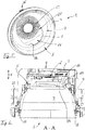
- FIGS Figures 1 to 25 A lamp 1 according to a first exemplary embodiment, as well as components of the lamp 1, are shown in FIGS Figures 1 to 25 shown.
- the lamp 1 is designed as a recessed ceiling spotlight or adjustable "downlight" and, with a compact design and a comparatively small diameter, creates a discreet ceiling appearance and a pleasant lighting atmosphere.
- Figure 1 shows the luminaire 1, which together with a substantially circular ring-like mounting frame 21 forms a lighting arrangement.
- the frame 21 can for example be inserted into a round opening in an Figure 1 suspended ceiling, not shown in detail.
- the mounting frame 21 can be fastened in the ceiling area by means of tab-like fastening devices 27, which are coupled to the frame 21, for example, at different heights and positions on an outside of the frame 21.
- the luminaire 1 is releasably latched into the frame 21 and can relative to the frame 21 about a central axis 22 of a reflector 4 relative to the frame 21 be twisted.
- the lamp 1 can be rotated about the central axis 22 in relation to the frame 21 by an angle of 360 degrees or more, or by an angle of slightly less than 360 degrees, for example by approximately 355 degrees.
- the lamp 1 has a light generating device 2, a helmet-like heat sink 3, an at least partially dome-like reflector 4 and an intermediate element 5.
- the cooling body 3 overlaps the reflector 4 and the intermediate element 5, as a result of which the reflector 4 and the intermediate element 5 are each received with a section in an inner region 24 of the cooling body 3, see Fig. 2 and 10 .
- the light generating device 2 comprises an LED device 23 with one or more LEDs, which provide the light to be emitted by the luminaire 1.
- Figure 10 shows a mounting surface 32 of the same in the inner region 24 of the heat sink 3, which is designed as a flat inner surface of the heat sink 3.
- the LED device 23 has an LED circuit board which is mounted directly on the heat sink 3 with the aid of the mounting surface 32.
- the light generating device 2 is fixed on the heat sink 3 in this way.
- the light generating device 2 is arranged such that it can emit light into an interior 7 of the reflector 4 during operation. This will be explained below.
- the luminaire 1 has a lens 19, which is set up and arranged to direct and / or focus the light provided by the light generating device 2.
- the lens 19 is for this purpose, see Figures 5 and 6 , arranged in front of the light generating device 19 and has a substantially circular-cylindrical outer shape.
- the intermediate element 5 which will be described in more detail below, has an essentially circular recess 14 in the form of a through opening, the shape and diameter of which are adapted to the shape and diameter of the lens 19. A portion of the lens 19 is received in the recess 14. The recess 14 thus forms a receiving area 20 for the lens 19.
- Figure 4 shows that the intermediate element 5 is arranged on a rear and outer side 41 of the reflector 4.
- the reflector 4 is provided with a passage 16 on its rear side, see in particular Figures 4 and 11-13 .
- the passage 16 is introduced as a passage opening in a curved, shell-like section 33 of the reflector 4. In a view along the central axis 22, see approx Figure 12 , the passage is slightly elongated and also rounded.
- the passage 16 is larger in terms of its area than the recess 14 of the intermediate element 5.
- the recess 14 and the passage 16 lie one above the other in such a way that the recess 14 is not covered by parts of the reflector 4.
- the lens 19 protrudes through the recess 14 into the passage 16, see Fig. 6 . In this way, light bundled and / or directed by the light generating device 2 through the lens 19 can be emitted into the interior 7 of the reflector 4.
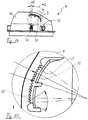
- the heat sink 3 is coupled to the reflector 4 such that it can pivot relative to the reflector 4 about a pivot axis 6 which is defined by two pivot pins 17 of the reflector 4 projecting radially outward. In this way, the heat sink 3 can be pivoted relative to the reflector 4 within a predefined pivot range 15, with the pivot range 15 about the pivot axis 6 being an angular range of approximately 30 degrees with respect to the central axis 22 in the first exemplary embodiment shown, see FIG Fig. 23 , is defined.
- the circumferential wall 30 has a cutout 31 in an area which extends approximately over half the circumference of the heat sink.
- Fig. 2 shows how the heat sink 3 in the vertical alignment of the heat sink 3 shown in this figure in one half of the circumference of the reflector 4 between the two pivot pins 17, in Fig. 2 on the left side, the shell-like section 33 of the reflector 4 largely takes up in itself, while in the other half of the circumference of the reflector 4 in this position of the heat sink 3, a part of the shell-like section 33 protrudes.
- the heat sink 3 and the reflector 4 thus overlap in FIG Fig. 2 on one side of the pivot axis 6 more than on the other.
- a targeted alignment of a light cone generated by the lamp 1 is possible by adjusting the cooling body 3 relative to the reflector 4 about the pivot axis 6.
- the cooling body 3 is pivoted together with the intermediate element 5, the lens 19 and the light generating device 2.
- a first end position of the heat sink 3 is in the Figures 2 and 20 to 22 shown, a second end position of the same in the Figures 23 to 25 , the end positions shown by way of example in the illustrated embodiment limit the angular range 15.
- the light is emitted into the interior space 7 of the reflector 4 along a main direction which is essentially parallel to the central axis 22 of the reflector 4.
- the luminaire 1 emits its light cone essentially parallel to the central axis 22, for example vertically downwards when installed in a horizontal ceiling.
- Fig. 23-25 it can be seen, for example, that components of the lamp 1 on the visible side S of the same advantageously do not protrude from the reflector 4 in any of the pivoting positions.
- the central axis 22 of the reflector 4 can remain unchanged, while the light emitted from the lamp 1 through the reflector 4 is aligned with the help of a pivoting of the heat sink 3 together with the light generating device 2 and the lens 19.
- the luminaire 1 thus always gives a discreet, unchanged ceiling appearance, but nevertheless enables an effective alignment of the light cone generated. The viewer does not perceive any change or impairment of the aesthetic appearance of the lamp 1 when adjusting the light cone.
- the central axis 22 and the pivot axis 6 are essentially perpendicular to one another, with the pivot axis 6 being oriented horizontally and the central axis 22 vertically in the case of an essentially horizontal installation of the frame 21 in the ceiling.
- the central axis 22 is in particular perpendicular to an installation plane, not shown in detail, which corresponds to the ceiling plane, for example. The rotation of the lamp 1 about the central axis 22 does not disturb the ceiling appearance.
- the heat sink 3 has, see for example Fig. 2 , 7, 8, 10 , Recesses 18, which are designed as round through openings and are arranged at a distance of 180 degrees along the circumference of the cooling body 3.
- the recesses 18 are provided adjacent to an outer edge 34 of the peripheral wall 30 and the two end regions of the cutout 31.
- the luminaire 1 can latch into the frame 21 by means of latching devices 35 arranged on the reflector 4.
- the locking devices 35 are each designed as a spring-loaded ball pointing radially outward.
- the locking devices 35 can also be referred to as ball catches.
- the balls are each received in a suitable receptacle 36 on the reflector 4.
- Three receptacles 36 for balls of the locking devices 35 are arranged at a distance corresponding to an angle W of 120 degrees around the central axis 22 on the outer circumference of the reflector 4, see in particular Fig. 12 .
- the balls can snap into a circumferential groove of the frame 21 and also enable the locked reflector 4 to be rotated about the central axis 22.
- the locking by means of the locking devices 35 is such that the locking connection of the lamp 1 and frame 21 can be released again, which also a simple dismantling of the lamp 1 is possible.
- the intermediate element 5 which is designed with a cap-like or shell-like shape, is in the Figures 16-19 shown in more detail.
- the intermediate element 5 On both sides of an axis of symmetry 37, see Fig. 17 , the intermediate element 5 each has a first section 9, each of the two first sections 9 being provided with a toothing 8.
- the intermediate element 5 is equipped with three peg-like guide devices 38 which are aligned parallel to one another and are arranged around the recess 14 at a distance corresponding to an angle of W 'of approximately 120 degrees.
- the guide devices 38 and the teeth 8 point in opposite directions.
- each set of teeth 8 has, for example, five teeth.
- the sections 9 are arranged symmetrically to the axis 37.
- Each of the two sections 11 is provided with teeth 10.
- Each of the serrations 10 is along an arc 13, see Fig. 15 , arranged, wherein the center of the circle of the arc 13 lies essentially on the axis 6.
- each of the serrations 10 has, for example, a number of 16 teeth along the arch 13.
- the sections 11 are arranged symmetrically to the axis 39.
- the heat sink 3 is, see for example Fig. 10 , equipped with three guide devices 40, which are designed as recesses in the cooling body 3 that are open towards the inner region 24.
- the shape and positioning of the guide devices 40 correspond to the guide devices 38 of the intermediate element 5 in such a way that the intermediate element 5 can be inserted into the inner region 24 and in this case the peg-like Guide devices 38 are each inserted into the recess-shaped guide devices 40.
- the intermediate element 5 is parallel to the direction of extension of the guide devices 38 along a displacement direction V, and thus for example in Fig. 6 mounted on the cooling body 3 such that it can be displaced in a straight line in the vertical direction.
- the intermediate element 5 can therefore be displaced parallel to the direction V relative to the cooling body 3.
- a spring device 12 designed as a compression spring is placed on each of the peg-shaped guide devices 38. See for example Figures 3 and 4 , in which the spring devices 12 are slipped onto pegs that serve as the guide devices 38.
- the guide devices 38 are each formed with a thicker and a thinner section which merge into one another in the area of a step 38 '.
- the spring device 12 can each sit on the step 38 ', see FIG Figures 3 and 4 . Lateral guidance can be achieved by an outer surface 38 ′′ of the thicker sections of the guide means 38.
- Figures 3 and 4 show the guide devices 38 in a first variant, in which the respectively thicker and thinner section are formed with an essentially cylindrical outer surface which is uninterrupted in the circumferential direction.
- the outer surfaces of the guide devices 38 are in the Figures 16-19 in a variant provided with additional longitudinal grooves 38 ''', but again the spring device 12 is seated on the step 38'.
- the spring devices 12 act on the intermediate element 5 with a spring force F parallel to the direction V, see for example Fig. 3, 4 which is oriented in the direction away from the heat sink 3 and towards the reflector 4.
- the spring devices 12 are supported on the heat sink 3.
- the teeth 8 are pressed against the teeth 10 and mesh with one another.
- the design of the teeth 8 is such that the teeth 8 of the shorter first section 9 along the circular arc 13 can engage in the teeth 10 of the longer second section 11 at different points.
- the teeth 8 and 10 are therefore designed to be coordinated with one another in order to be able to realize such an engagement.
- the lamp 1 makes it possible to change the heat sink 3 and thus the alignment of the emitted light without the lamp 1 having to be removed from the frame 21.
- an operator presses from the visible side S of the lamp 1, see for example Fig. 5 or 6 , against the spring force F on the lens 19.
- the lens 19 is displaceable relative to the heat sink 3 and coupled to the intermediate element 5 in such a way that, by pressing on the lens 19, the teeth 8 and 10 stand out from one another against the direction of force F and disengage.
- the displacement path by which the intermediate element 5 can be displaced against the spring force F is sufficient so that the toothings 8, 10 can disengage.
- the lens 19 is thus pressed in the direction of the heat sink 3.
- the heat sink 3 can be pivoted about the pivot axis 6 together with the light generating device 2, the intermediate element 5 and the lens 19.
- the operator removes the pressure from the lens 19, whereby the engagement of the teeth 8 and 10 is restored and the desired alignment of the heat sink 3 is fixed.
- the cooling body 3 can therefore be held in any desired of the possible positions in the pivoting range 15 thereof.
- the lens 19 can be fastened to the intermediate element 5 in the recess 14, for example.
- Adjustment about the central axis 22 can also take place without having to remove the lamp 1 from the frame 21.
- the lamp 1 can be adjusted in many ways without the need for dismantling.
- one dimension of the passage 16 in the reflector 4 essentially corresponds to a diameter of the recess 14 in the intermediate element.
- the lens 19 protrudes through the recess 14, as a result of which, with the aid of the lens 19, directed and / or focused light can be emitted into the interior 7 of the reflector 4.
- the intermediate element 5 moves with the heat sink 3 and moves in the area of the outside 41 of the reflector 4 in such a way that the passage 16 always remains essentially covered outside the area of the lens 19. See for example Fig. 5 doing this for a vertical position of the heat sink 3 shows, and for example Fig. 24 which illustrates the covering of the passage for a pivoted position of the heat sink 3.
- the intermediate element 5 thus acts as a cover element which is displaceable on the reflector outer side 41 and which moves with the cooling body 3 when it is pivoted about the axis 6.
- An area 25 of the passage 16, through which the lens 19 protrudes in a pivoted position of the cooling body 3, is used for the emission of light into the interior 7, while a remaining area 26, or in the case of an intermediate position, remaining areas of the passage 16 outside the Area 25 is / are essentially covered by the intermediate element 5 in each pivoting position of the cooling body 3 in the pivoting area 15.
- Fig. 21 shows that the intermediate element 5 avoids such a gap in the vertical end position of the cooling body 3, this is done Fig. 24 for an inclined position of the heat sink 3 clearly.
- the area 26 is covered by the intermediate element 5, although the heat sink 3 does not completely cover the area 26 in this figure.
- the intermediate element 5 covers the area 26 present in the position shown in spite of the simultaneous overlap by the cooling body 3.
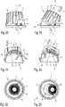
- FIG Figures 26-30 A luminaire 1 according to a variant of the first exemplary embodiment with a modified heat sink 3 is shown in FIG Figures 26-30 , the lamp 1 according to Fig. 26-30 only differs from the lamp 1, as was described above for the first exemplary embodiment, that in Fig. 26-30 the heat sink 3 is additionally perforated between some of the cooling fins 28, and thus has openings 42 between some of the fins 28.
- a section of the intermediate element 5 is visible through the openings 28, which in this case again advantageously provides a covering function in addition to the function of the teeth 8.
- the openings 42 can contribute to saving weight and improve ventilation of the outside of the reflector 41 and of the space between the heat sink 3 and reflector 4.
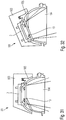
- a luminaire 101 with a light generating device 2, a heat sink 103, a reflector 104 and an intermediate element 105 according to a second exemplary embodiment show the Figures 31 and 32 .
- the second exemplary embodiment differs from the first exemplary embodiment with regard to the shape of the cooling body 103, which in the second exemplary embodiment is on the side of the same which, when the cooling body 103 is pivoted, moves away from and into an opening of the reflector 104 Fig. 32 moves upwards, extends less far downwards over the reflector 104 and thus indeed engages over the reflector 104, but takes up less largely in itself.
- the heat sink 3, 103 is formed from a metal material, for example die-cast.
- the reflector 4, 104 and the intermediate element 5, 105 are each made of a plastic material, for example injection molded.
- the reflector 4, 104 and the intermediate element 5, 105 can be made of a polycarbonate.
- the reflector 4, 104, and if desired also the intermediate element 5, 105 can be provided in a number of different colors, for example black, white, copper-colored, chrome-colored or gold-colored.
- the reflector 4, 104, and if desired also the intermediate element 5, 105 can be vacuum-coated.
Landscapes
- Engineering & Computer Science (AREA)
- General Engineering & Computer Science (AREA)
- Arrangement Of Elements, Cooling, Sealing, Or The Like Of Lighting Devices (AREA)
- Non-Portable Lighting Devices Or Systems Thereof (AREA)
Priority Applications (1)
| Application Number | Priority Date | Filing Date | Title |
|---|---|---|---|
| PL19160428T PL3534059T3 (pl) | 2018-03-02 | 2019-03-04 | Oprawa oświetleniowa |
Applications Claiming Priority (1)
| Application Number | Priority Date | Filing Date | Title |
|---|---|---|---|
| DE102018001652.9A DE102018001652B4 (de) | 2018-03-02 | 2018-03-02 | Leuchte |
Publications (3)
| Publication Number | Publication Date |
|---|---|
| EP3534059A2 EP3534059A2 (de) | 2019-09-04 |
| EP3534059A3 EP3534059A3 (de) | 2019-11-13 |
| EP3534059B1 true EP3534059B1 (de) | 2020-12-09 |
Family
ID=65685197
Family Applications (1)
| Application Number | Title | Priority Date | Filing Date |
|---|---|---|---|
| EP19160428.9A Active EP3534059B1 (de) | 2018-03-02 | 2019-03-04 | Leuchte |
Country Status (5)
| Country | Link |
|---|---|
| US (1) | US10627085B2 (pl) |
| EP (1) | EP3534059B1 (pl) |
| AT (1) | AT520986B1 (pl) |
| DE (1) | DE102018001652B4 (pl) |
| PL (1) | PL3534059T3 (pl) |
Families Citing this family (8)
| Publication number | Priority date | Publication date | Assignee | Title |
|---|---|---|---|---|
| US11215332B2 (en) * | 2019-05-02 | 2022-01-04 | Intense Lighting, Inc. | Lighting fixture having an adjustable optic system |
| US10962203B1 (en) | 2020-03-30 | 2021-03-30 | Electronic Theatre Controls, Inc. | Adjustable light fixture |
| US11708965B2 (en) | 2020-05-11 | 2023-07-25 | Wangs Alliance Corporation | Suspended LED fixtures having adjustable cord support |
| CN114576585B (zh) * | 2022-01-27 | 2025-08-01 | 新文行照明有限公司 | 一种可调节照射角度的筒灯及筒灯的装配方法 |
| US11802682B1 (en) | 2022-08-29 | 2023-10-31 | Wangs Alliance Corporation | Modular articulating lighting |
| DE102023205718B3 (de) | 2023-06-19 | 2024-10-31 | Ridi Leuchten Gmbh | Einbauleuchte mit Verstellmöglichkeit für die Lichthauptausbreitungsrichtung |
| US12135119B1 (en) * | 2024-02-27 | 2024-11-05 | Amerlux, Llc | Frame assembly |
| WO2026057295A1 (en) * | 2024-09-10 | 2026-03-19 | Signify Holding B.V. | An adjustable light fixture and an adjustable lamp |
Family Cites Families (8)
| Publication number | Priority date | Publication date | Assignee | Title |
|---|---|---|---|---|
| DE19615639B4 (de) | 1996-04-21 | 2009-05-07 | Acl Lichttechnik Gmbh | Einbauleuchte |
| DE20313905U1 (de) | 2003-09-04 | 2005-01-05 | Erco Leuchten Gmbh | Leuchte zur Anbringung an einer Gebäudefläche oder einer Gebäudeteilfläche |
| US7934860B2 (en) * | 2009-04-03 | 2011-05-03 | Frank Tsao | Lighting fixture with angle adjustment arrangement |
| DE102009057764A1 (de) | 2009-10-13 | 2011-04-14 | Erco Gmbh | Modul-Bausystem für eine Einbauleuchte |
| JP6254069B2 (ja) * | 2014-11-05 | 2017-12-27 | ミネベアミツミ株式会社 | 角度調整装置および該角度調整装置を備える照明装置 |
| EP3217071B1 (de) * | 2016-03-11 | 2018-06-27 | Prolicht GmbH | Einbaustrahler für den deckeneinbau oder deckenanbau |
| US9735083B1 (en) * | 2016-04-18 | 2017-08-15 | International Business Machines Corporation | Adjustable heat sink fin spacing |
| US10436434B2 (en) * | 2016-04-26 | 2019-10-08 | Lighting Science Group Corporation | Gimbal luminaire |
-
2018
- 2018-03-02 DE DE102018001652.9A patent/DE102018001652B4/de not_active Expired - Fee Related
- 2018-04-04 AT ATA50270/2018A patent/AT520986B1/de active
-
2019
- 2019-03-04 EP EP19160428.9A patent/EP3534059B1/de active Active
- 2019-03-04 PL PL19160428T patent/PL3534059T3/pl unknown
- 2019-03-04 US US16/291,397 patent/US10627085B2/en active Active
Non-Patent Citations (1)
| Title |
|---|
| None * |
Also Published As
| Publication number | Publication date |
|---|---|
| AT520986A3 (de) | 2020-06-15 |
| EP3534059A3 (de) | 2019-11-13 |
| DE102018001652B4 (de) | 2019-10-02 |
| PL3534059T3 (pl) | 2021-07-26 |
| AT520986A2 (de) | 2019-09-15 |
| AT520986B1 (de) | 2022-09-15 |
| DE102018001652A1 (de) | 2019-09-05 |
| US20190271456A1 (en) | 2019-09-05 |
| EP3534059A2 (de) | 2019-09-04 |
| US10627085B2 (en) | 2020-04-21 |
Similar Documents
| Publication | Publication Date | Title |
|---|---|---|
| EP3534059B1 (de) | Leuchte | |
| EP2131103B1 (de) | Lichtkanalsystem | |
| EP2238387B1 (de) | Led-leuchte mit verstellbarer lichtquelle | |
| EP1848923B1 (de) | Leuchte mit einem strahler und verstellbare haltevorrichtung für einen strahler | |
| EP2735787B1 (de) | Einbauleuchte | |
| DE102015101829B4 (de) | Spannklaue zur Anbringung an einer Gleitschiene eines Operationstisches | |
| DE202009006095U1 (de) | LED-Lampe mit mehrschichtigen Lichtquellen | |
| EP1967095B1 (de) | Stuhl mit neigbarem Sitz | |
| EP3335591A1 (de) | Mehrfach-arretiervorrichtung für einen arretierbeschlag für eine zarge, zarge und schubkasten | |
| AT515646B1 (de) | Halteanordnung für ein Funktionsbauteil einer Beleuchtungsvorrichtung, sowie Beleuchtungsvorrichtung | |
| EP1584864B1 (de) | Reflektor für eine Leuchte, mit einer verstellbaren Reflektorwand und Leuchte mit einem solchen Reflektor | |
| EP4056887B1 (de) | Nivellierbare stehleuchte | |
| DE10321282B4 (de) | Wandleuchte | |
| EP2085684B1 (de) | Leuchte mit selbsttragender Reflektoreinheit | |
| DE202008006321U1 (de) | Verstellbares Lampengerät | |
| DE10309087A1 (de) | Befestigungseinrichtung für Kraftfahrzeug-Scheinwerfer | |
| EP2322851A2 (de) | Leuchte und Verschluss für Leuchte | |
| DE102013210377B4 (de) | Fixiersystem zum Fixieren einer Helmschale | |
| EP1567804B1 (de) | Reflektoranordnung mit hintereinander angeordneten leuchtmitteln | |
| DE202022102261U1 (de) | Flächenleuchte mit rückseitiger (Sekundär-)Beleuchtung | |
| DE202024103530U1 (de) | Zweiwinkel-Beleuchtungsmodul | |
| DE202023102977U1 (de) | Stehleuchte mit einstellbarem Leuchtenkopf mit Anschlag | |
| DE102010013655B4 (de) | Leuchte mit geführtem Fassungshalter | |
| DE9204201U1 (de) | Reflektorverstellung für eine Leuchte mit rotationssymmetrischem Reflektor | |
| DE29916324U1 (de) | Leuchte |
Legal Events
| Date | Code | Title | Description |
|---|---|---|---|
| PUAI | Public reference made under article 153(3) epc to a published international application that has entered the european phase |
Free format text: ORIGINAL CODE: 0009012 |
|
| STAA | Information on the status of an ep patent application or granted ep patent |
Free format text: STATUS: THE APPLICATION HAS BEEN PUBLISHED |
|
| AK | Designated contracting states |
Kind code of ref document: A2 Designated state(s): AL AT BE BG CH CY CZ DE DK EE ES FI FR GB GR HR HU IE IS IT LI LT LU LV MC MK MT NL NO PL PT RO RS SE SI SK SM TR |
|
| AX | Request for extension of the european patent |
Extension state: BA ME |
|
| PUAL | Search report despatched |
Free format text: ORIGINAL CODE: 0009013 |
|
| AK | Designated contracting states |
Kind code of ref document: A3 Designated state(s): AL AT BE BG CH CY CZ DE DK EE ES FI FR GB GR HR HU IE IS IT LI LT LU LV MC MK MT NL NO PL PT RO RS SE SI SK SM TR |
|
| AX | Request for extension of the european patent |
Extension state: BA ME |
|
| RIC1 | Information provided on ipc code assigned before grant |
Ipc: F21S 8/02 20060101AFI20191009BHEP Ipc: F21V 21/30 20060101ALI20191009BHEP |
|
| STAA | Information on the status of an ep patent application or granted ep patent |
Free format text: STATUS: REQUEST FOR EXAMINATION WAS MADE |
|
| 17P | Request for examination filed |
Effective date: 20200330 |
|
| RBV | Designated contracting states (corrected) |
Designated state(s): AL AT BE BG CH CY CZ DE DK EE ES FI FR GB GR HR HU IE IS IT LI LT LU LV MC MK MT NL NO PL PT RO RS SE SI SK SM TR |
|
| GRAP | Despatch of communication of intention to grant a patent |
Free format text: ORIGINAL CODE: EPIDOSNIGR1 |
|
| STAA | Information on the status of an ep patent application or granted ep patent |
Free format text: STATUS: GRANT OF PATENT IS INTENDED |
|
| INTG | Intention to grant announced |
Effective date: 20200710 |
|
| GRAS | Grant fee paid |
Free format text: ORIGINAL CODE: EPIDOSNIGR3 |
|
| GRAA | (expected) grant |
Free format text: ORIGINAL CODE: 0009210 |
|
| STAA | Information on the status of an ep patent application or granted ep patent |
Free format text: STATUS: THE PATENT HAS BEEN GRANTED |
|
| AK | Designated contracting states |
Kind code of ref document: B1 Designated state(s): AL AT BE BG CH CY CZ DE DK EE ES FI FR GB GR HR HU IE IS IT LI LT LU LV MC MK MT NL NO PL PT RO RS SE SI SK SM TR |
|
| REG | Reference to a national code |
Ref country code: GB Ref legal event code: FG4D Free format text: NOT ENGLISH |
|
| REG | Reference to a national code |
Ref country code: CH Ref legal event code: EP Ref country code: AT Ref legal event code: REF Ref document number: 1343815 Country of ref document: AT Kind code of ref document: T Effective date: 20201215 |
|
| REG | Reference to a national code |
Ref country code: DE Ref legal event code: R096 Ref document number: 502019000491 Country of ref document: DE |
|
| REG | Reference to a national code |
Ref country code: IE Ref legal event code: FG4D Free format text: LANGUAGE OF EP DOCUMENT: GERMAN |
|
| REG | Reference to a national code |
Ref country code: CH Ref legal event code: NV Representative=s name: NOVAGRAAF INTERNATIONAL SA, CH |
|
| REG | Reference to a national code |
Ref country code: SE Ref legal event code: TRGR |
|
| PG25 | Lapsed in a contracting state [announced via postgrant information from national office to epo] |
Ref country code: GR Free format text: LAPSE BECAUSE OF FAILURE TO SUBMIT A TRANSLATION OF THE DESCRIPTION OR TO PAY THE FEE WITHIN THE PRESCRIBED TIME-LIMIT Effective date: 20210310 Ref country code: NO Free format text: LAPSE BECAUSE OF FAILURE TO SUBMIT A TRANSLATION OF THE DESCRIPTION OR TO PAY THE FEE WITHIN THE PRESCRIBED TIME-LIMIT Effective date: 20210309 Ref country code: FI Free format text: LAPSE BECAUSE OF FAILURE TO SUBMIT A TRANSLATION OF THE DESCRIPTION OR TO PAY THE FEE WITHIN THE PRESCRIBED TIME-LIMIT Effective date: 20201209 Ref country code: RS Free format text: LAPSE BECAUSE OF FAILURE TO SUBMIT A TRANSLATION OF THE DESCRIPTION OR TO PAY THE FEE WITHIN THE PRESCRIBED TIME-LIMIT Effective date: 20201209 |
|
| PG25 | Lapsed in a contracting state [announced via postgrant information from national office to epo] |
Ref country code: LV Free format text: LAPSE BECAUSE OF FAILURE TO SUBMIT A TRANSLATION OF THE DESCRIPTION OR TO PAY THE FEE WITHIN THE PRESCRIBED TIME-LIMIT Effective date: 20201209 Ref country code: BG Free format text: LAPSE BECAUSE OF FAILURE TO SUBMIT A TRANSLATION OF THE DESCRIPTION OR TO PAY THE FEE WITHIN THE PRESCRIBED TIME-LIMIT Effective date: 20210309 |
|
| REG | Reference to a national code |
Ref country code: NL Ref legal event code: MP Effective date: 20201209 |
|
| PG25 | Lapsed in a contracting state [announced via postgrant information from national office to epo] |
Ref country code: NL Free format text: LAPSE BECAUSE OF FAILURE TO SUBMIT A TRANSLATION OF THE DESCRIPTION OR TO PAY THE FEE WITHIN THE PRESCRIBED TIME-LIMIT Effective date: 20201209 Ref country code: HR Free format text: LAPSE BECAUSE OF FAILURE TO SUBMIT A TRANSLATION OF THE DESCRIPTION OR TO PAY THE FEE WITHIN THE PRESCRIBED TIME-LIMIT Effective date: 20201209 |
|
| REG | Reference to a national code |
Ref country code: LT Ref legal event code: MG9D |
|
| PG25 | Lapsed in a contracting state [announced via postgrant information from national office to epo] |
Ref country code: CZ Free format text: LAPSE BECAUSE OF FAILURE TO SUBMIT A TRANSLATION OF THE DESCRIPTION OR TO PAY THE FEE WITHIN THE PRESCRIBED TIME-LIMIT Effective date: 20201209 Ref country code: EE Free format text: LAPSE BECAUSE OF FAILURE TO SUBMIT A TRANSLATION OF THE DESCRIPTION OR TO PAY THE FEE WITHIN THE PRESCRIBED TIME-LIMIT Effective date: 20201209 Ref country code: SM Free format text: LAPSE BECAUSE OF FAILURE TO SUBMIT A TRANSLATION OF THE DESCRIPTION OR TO PAY THE FEE WITHIN THE PRESCRIBED TIME-LIMIT Effective date: 20201209 Ref country code: SK Free format text: LAPSE BECAUSE OF FAILURE TO SUBMIT A TRANSLATION OF THE DESCRIPTION OR TO PAY THE FEE WITHIN THE PRESCRIBED TIME-LIMIT Effective date: 20201209 Ref country code: PT Free format text: LAPSE BECAUSE OF FAILURE TO SUBMIT A TRANSLATION OF THE DESCRIPTION OR TO PAY THE FEE WITHIN THE PRESCRIBED TIME-LIMIT Effective date: 20210409 Ref country code: RO Free format text: LAPSE BECAUSE OF FAILURE TO SUBMIT A TRANSLATION OF THE DESCRIPTION OR TO PAY THE FEE WITHIN THE PRESCRIBED TIME-LIMIT Effective date: 20201209 Ref country code: LT Free format text: LAPSE BECAUSE OF FAILURE TO SUBMIT A TRANSLATION OF THE DESCRIPTION OR TO PAY THE FEE WITHIN THE PRESCRIBED TIME-LIMIT Effective date: 20201209 |
|
| REG | Reference to a national code |
Ref country code: DE Ref legal event code: R097 Ref document number: 502019000491 Country of ref document: DE |
|
| PG25 | Lapsed in a contracting state [announced via postgrant information from national office to epo] |
Ref country code: IS Free format text: LAPSE BECAUSE OF FAILURE TO SUBMIT A TRANSLATION OF THE DESCRIPTION OR TO PAY THE FEE WITHIN THE PRESCRIBED TIME-LIMIT Effective date: 20210409 |
|
| PLBE | No opposition filed within time limit |
Free format text: ORIGINAL CODE: 0009261 |
|
| STAA | Information on the status of an ep patent application or granted ep patent |
Free format text: STATUS: NO OPPOSITION FILED WITHIN TIME LIMIT |
|
| PG25 | Lapsed in a contracting state [announced via postgrant information from national office to epo] |
Ref country code: MC Free format text: LAPSE BECAUSE OF FAILURE TO SUBMIT A TRANSLATION OF THE DESCRIPTION OR TO PAY THE FEE WITHIN THE PRESCRIBED TIME-LIMIT Effective date: 20201209 Ref country code: AL Free format text: LAPSE BECAUSE OF FAILURE TO SUBMIT A TRANSLATION OF THE DESCRIPTION OR TO PAY THE FEE WITHIN THE PRESCRIBED TIME-LIMIT Effective date: 20201209 |
|
| 26N | No opposition filed |
Effective date: 20210910 |
|
| PG25 | Lapsed in a contracting state [announced via postgrant information from national office to epo] |
Ref country code: DK Free format text: LAPSE BECAUSE OF FAILURE TO SUBMIT A TRANSLATION OF THE DESCRIPTION OR TO PAY THE FEE WITHIN THE PRESCRIBED TIME-LIMIT Effective date: 20201209 Ref country code: SI Free format text: LAPSE BECAUSE OF FAILURE TO SUBMIT A TRANSLATION OF THE DESCRIPTION OR TO PAY THE FEE WITHIN THE PRESCRIBED TIME-LIMIT Effective date: 20201209 |
|
| PG25 | Lapsed in a contracting state [announced via postgrant information from national office to epo] |
Ref country code: IE Free format text: LAPSE BECAUSE OF NON-PAYMENT OF DUE FEES Effective date: 20210304 Ref country code: LU Free format text: LAPSE BECAUSE OF NON-PAYMENT OF DUE FEES Effective date: 20210304 Ref country code: ES Free format text: LAPSE BECAUSE OF FAILURE TO SUBMIT A TRANSLATION OF THE DESCRIPTION OR TO PAY THE FEE WITHIN THE PRESCRIBED TIME-LIMIT Effective date: 20201209 |
|
| PG25 | Lapsed in a contracting state [announced via postgrant information from national office to epo] |
Ref country code: IS Free format text: LAPSE BECAUSE OF FAILURE TO SUBMIT A TRANSLATION OF THE DESCRIPTION OR TO PAY THE FEE WITHIN THE PRESCRIBED TIME-LIMIT Effective date: 20210409 |
|
| PG25 | Lapsed in a contracting state [announced via postgrant information from national office to epo] |
Ref country code: CY Free format text: LAPSE BECAUSE OF FAILURE TO SUBMIT A TRANSLATION OF THE DESCRIPTION OR TO PAY THE FEE WITHIN THE PRESCRIBED TIME-LIMIT Effective date: 20201209 |
|
| PG25 | Lapsed in a contracting state [announced via postgrant information from national office to epo] |
Ref country code: HU Free format text: LAPSE BECAUSE OF FAILURE TO SUBMIT A TRANSLATION OF THE DESCRIPTION OR TO PAY THE FEE WITHIN THE PRESCRIBED TIME-LIMIT; INVALID AB INITIO Effective date: 20190304 |
|
| PG25 | Lapsed in a contracting state [announced via postgrant information from national office to epo] |
Ref country code: MK Free format text: LAPSE BECAUSE OF FAILURE TO SUBMIT A TRANSLATION OF THE DESCRIPTION OR TO PAY THE FEE WITHIN THE PRESCRIBED TIME-LIMIT Effective date: 20201209 |
|
| PG25 | Lapsed in a contracting state [announced via postgrant information from national office to epo] |
Ref country code: TR Free format text: LAPSE BECAUSE OF FAILURE TO SUBMIT A TRANSLATION OF THE DESCRIPTION OR TO PAY THE FEE WITHIN THE PRESCRIBED TIME-LIMIT Effective date: 20201209 |
|
| PG25 | Lapsed in a contracting state [announced via postgrant information from national office to epo] |
Ref country code: MT Free format text: LAPSE BECAUSE OF FAILURE TO SUBMIT A TRANSLATION OF THE DESCRIPTION OR TO PAY THE FEE WITHIN THE PRESCRIBED TIME-LIMIT Effective date: 20201209 |
|
| PGFP | Annual fee paid to national office [announced via postgrant information from national office to epo] |
Ref country code: DE Payment date: 20250331 Year of fee payment: 7 |
|
| PGFP | Annual fee paid to national office [announced via postgrant information from national office to epo] |
Ref country code: PL Payment date: 20250218 Year of fee payment: 7 |
|
| PGFP | Annual fee paid to national office [announced via postgrant information from national office to epo] |
Ref country code: CH Payment date: 20250401 Year of fee payment: 7 |
|
| REG | Reference to a national code |
Ref country code: CH Ref legal event code: U11 Free format text: ST27 STATUS EVENT CODE: U-0-0-U10-U11 (AS PROVIDED BY THE NATIONAL OFFICE) Effective date: 20260401 |
|
| PGFP | Annual fee paid to national office [announced via postgrant information from national office to epo] |
Ref country code: SE Payment date: 20260319 Year of fee payment: 8 |
|
| PGFP | Annual fee paid to national office [announced via postgrant information from national office to epo] |
Ref country code: GB Payment date: 20260324 Year of fee payment: 8 |
|
| PGFP | Annual fee paid to national office [announced via postgrant information from national office to epo] |
Ref country code: AT Payment date: 20260320 Year of fee payment: 8 |
|
| PGFP | Annual fee paid to national office [announced via postgrant information from national office to epo] |
Ref country code: BE Payment date: 20260319 Year of fee payment: 8 Ref country code: IT Payment date: 20260324 Year of fee payment: 8 |
|
| PGFP | Annual fee paid to national office [announced via postgrant information from national office to epo] |
Ref country code: FR Payment date: 20260320 Year of fee payment: 8 |