EP3533937B1 - Versorgungssystem der wasserbasierenden flüssigkeiten - Google Patents
Versorgungssystem der wasserbasierenden flüssigkeiten Download PDFInfo
- Publication number
- EP3533937B1 EP3533937B1 EP18159914.3A EP18159914A EP3533937B1 EP 3533937 B1 EP3533937 B1 EP 3533937B1 EP 18159914 A EP18159914 A EP 18159914A EP 3533937 B1 EP3533937 B1 EP 3533937B1
- Authority
- EP
- European Patent Office
- Prior art keywords
- water
- tank
- liquid
- soda
- liquid supply
- Prior art date
- Legal status (The legal status is an assumption and is not a legal conclusion. Google has not performed a legal analysis and makes no representation as to the accuracy of the status listed.)
- Active
Links
Images


Classifications
-
- B—PERFORMING OPERATIONS; TRANSPORTING
- B67—OPENING, CLOSING OR CLEANING BOTTLES, JARS OR SIMILAR CONTAINERS; LIQUID HANDLING
- B67D—DISPENSING, DELIVERING OR TRANSFERRING LIQUIDS, NOT OTHERWISE PROVIDED FOR
- B67D1/00—Apparatus or devices for dispensing beverages on draught
- B67D1/08—Details
- B67D1/12—Flow or pressure control devices or systems, e.g. valves, gas pressure control, level control in storage containers
-
- E—FIXED CONSTRUCTIONS
- E03—WATER SUPPLY; SEWERAGE
- E03C—DOMESTIC PLUMBING INSTALLATIONS FOR FRESH WATER OR WASTE WATER; SINKS
- E03C1/00—Domestic plumbing installations for fresh water or waste water; Sinks
- E03C1/02—Plumbing installations for fresh water
-
- A—HUMAN NECESSITIES
- A23—FOODS OR FOODSTUFFS; TREATMENT THEREOF, NOT COVERED BY OTHER CLASSES
- A23L—FOODS, FOODSTUFFS OR NON-ALCOHOLIC BEVERAGES, NOT OTHERWISE PROVIDED FOR; PREPARATION OR TREATMENT THEREOF
- A23L2/00—Non-alcoholic beverages; Dry compositions or concentrates therefor; Preparation or treatment thereof
- A23L2/52—Adding ingredients
- A23L2/54—Mixing with gases
-
- A—HUMAN NECESSITIES
- A61—MEDICAL OR VETERINARY SCIENCE; HYGIENE
- A61L—METHODS OR APPARATUS FOR STERILISING MATERIALS OR OBJECTS IN GENERAL; DISINFECTION, STERILISATION OR DEODORISATION OF AIR; CHEMICAL ASPECTS OF BANDAGES, DRESSINGS, ABSORBENT PADS OR SURGICAL ARTICLES; MATERIALS FOR BANDAGES, DRESSINGS, ABSORBENT PADS OR SURGICAL ARTICLES
- A61L2/00—Disinfection or sterilisation of materials or objects, in general; Accessories therefor
- A61L2/02—Disinfection or sterilisation of materials or objects, in general; Accessories therefor using physical processes
- A61L2/08—Radiation
- A61L2/10—Ultraviolet [UV] radiation
-
- B—PERFORMING OPERATIONS; TRANSPORTING
- B01—PHYSICAL OR CHEMICAL PROCESSES OR APPARATUS IN GENERAL
- B01F—MIXING, e.g. DISSOLVING, EMULSIFYING OR DISPERSING
- B01F23/00—Mixing according to the phases to be mixed, e.g. dispersing or emulsifying
- B01F23/20—Mixing gases with liquids
- B01F23/23—Mixing gases with liquids by introducing gases into liquid media, e.g. for producing aerated liquids
- B01F23/236—Mixing gases with liquids by introducing gases into liquid media, e.g. for producing aerated liquids specially adapted for aerating or carbonating beverages
-
- B—PERFORMING OPERATIONS; TRANSPORTING
- B67—OPENING, CLOSING OR CLEANING BOTTLES, JARS OR SIMILAR CONTAINERS; LIQUID HANDLING
- B67D—DISPENSING, DELIVERING OR TRANSFERRING LIQUIDS, NOT OTHERWISE PROVIDED FOR
- B67D1/00—Apparatus or devices for dispensing beverages on draught
- B67D1/0015—Apparatus or devices for dispensing beverages on draught the beverage being prepared by mixing at least two liquid components
- B67D1/0021—Apparatus or devices for dispensing beverages on draught the beverage being prepared by mixing at least two liquid components the components being mixed at the time of dispensing, i.e. post-mix dispensers
- B67D1/0022—Apparatus or devices for dispensing beverages on draught the beverage being prepared by mixing at least two liquid components the components being mixed at the time of dispensing, i.e. post-mix dispensers the apparatus comprising means for automatically controlling the amount to be dispensed
-
- B—PERFORMING OPERATIONS; TRANSPORTING
- B67—OPENING, CLOSING OR CLEANING BOTTLES, JARS OR SIMILAR CONTAINERS; LIQUID HANDLING
- B67D—DISPENSING, DELIVERING OR TRANSFERRING LIQUIDS, NOT OTHERWISE PROVIDED FOR
- B67D1/00—Apparatus or devices for dispensing beverages on draught
- B67D1/0042—Details of specific parts of the dispensers
- B67D1/0057—Carbonators
- B67D1/0058—In-line carbonators
- B67D1/0059—In-line carbonators in combination with a mixer tap
-
- B—PERFORMING OPERATIONS; TRANSPORTING
- B67—OPENING, CLOSING OR CLEANING BOTTLES, JARS OR SIMILAR CONTAINERS; LIQUID HANDLING
- B67D—DISPENSING, DELIVERING OR TRANSFERRING LIQUIDS, NOT OTHERWISE PROVIDED FOR
- B67D1/00—Apparatus or devices for dispensing beverages on draught
- B67D1/04—Apparatus utilising compressed air or other gas acting directly or indirectly on beverages in storage containers
- B67D1/0406—Apparatus utilising compressed air or other gas acting directly or indirectly on beverages in storage containers with means for carbonating the beverage, or for maintaining its carbonation
-
- B—PERFORMING OPERATIONS; TRANSPORTING
- B67—OPENING, CLOSING OR CLEANING BOTTLES, JARS OR SIMILAR CONTAINERS; LIQUID HANDLING
- B67D—DISPENSING, DELIVERING OR TRANSFERRING LIQUIDS, NOT OTHERWISE PROVIDED FOR
- B67D1/00—Apparatus or devices for dispensing beverages on draught
- B67D1/08—Details
- B67D1/0857—Cooling arrangements
-
- C—CHEMISTRY; METALLURGY
- C02—TREATMENT OF WATER, WASTE WATER, SEWAGE, OR SLUDGE
- C02F—TREATMENT OF WATER, WASTE WATER, SEWAGE, OR SLUDGE
- C02F1/00—Treatment of water, waste water, or sewage
- C02F1/001—Processes for the treatment of water whereby the filtration technique is of importance
- C02F1/003—Processes for the treatment of water whereby the filtration technique is of importance using household-type filters for producing potable water, e.g. pitchers, bottles, faucet mounted devices
-
- C—CHEMISTRY; METALLURGY
- C02—TREATMENT OF WATER, WASTE WATER, SEWAGE, OR SLUDGE
- C02F—TREATMENT OF WATER, WASTE WATER, SEWAGE, OR SLUDGE
- C02F1/00—Treatment of water, waste water, or sewage
- C02F1/008—Control or steering systems not provided for elsewhere in subclass C02F
-
- C—CHEMISTRY; METALLURGY
- C02—TREATMENT OF WATER, WASTE WATER, SEWAGE, OR SLUDGE
- C02F—TREATMENT OF WATER, WASTE WATER, SEWAGE, OR SLUDGE
- C02F1/00—Treatment of water, waste water, or sewage
- C02F1/30—Treatment of water, waste water, or sewage by irradiation
- C02F1/32—Treatment of water, waste water, or sewage by irradiation with ultraviolet light
- C02F1/325—Irradiation devices or lamp constructions
-
- C—CHEMISTRY; METALLURGY
- C02—TREATMENT OF WATER, WASTE WATER, SEWAGE, OR SLUDGE
- C02F—TREATMENT OF WATER, WASTE WATER, SEWAGE, OR SLUDGE
- C02F1/00—Treatment of water, waste water, or sewage
- C02F1/68—Treatment of water, waste water, or sewage by addition of specified substances, e.g. trace elements, for ameliorating potable water
-
- E—FIXED CONSTRUCTIONS
- E03—WATER SUPPLY; SEWERAGE
- E03C—DOMESTIC PLUMBING INSTALLATIONS FOR FRESH WATER OR WASTE WATER; SINKS
- E03C1/00—Domestic plumbing installations for fresh water or waste water; Sinks
- E03C1/02—Plumbing installations for fresh water
- E03C1/04—Water-basin installations specially adapted to wash-basins or baths
- E03C1/0404—Constructional or functional features of the spout
-
- E—FIXED CONSTRUCTIONS
- E03—WATER SUPPLY; SEWERAGE
- E03C—DOMESTIC PLUMBING INSTALLATIONS FOR FRESH WATER OR WASTE WATER; SINKS
- E03C1/00—Domestic plumbing installations for fresh water or waste water; Sinks
- E03C1/02—Plumbing installations for fresh water
- E03C1/04—Water-basin installations specially adapted to wash-basins or baths
- E03C1/0411—Taps specially designed for dispensing boiling water
-
- E—FIXED CONSTRUCTIONS
- E03—WATER SUPPLY; SEWERAGE
- E03C—DOMESTIC PLUMBING INSTALLATIONS FOR FRESH WATER OR WASTE WATER; SINKS
- E03C1/00—Domestic plumbing installations for fresh water or waste water; Sinks
- E03C1/02—Plumbing installations for fresh water
- E03C1/04—Water-basin installations specially adapted to wash-basins or baths
- E03C1/044—Water-basin installations specially adapted to wash-basins or baths having a heating or cooling apparatus in the supply line
-
- E—FIXED CONSTRUCTIONS
- E03—WATER SUPPLY; SEWERAGE
- E03C—DOMESTIC PLUMBING INSTALLATIONS FOR FRESH WATER OR WASTE WATER; SINKS
- E03C1/00—Domestic plumbing installations for fresh water or waste water; Sinks
- E03C1/02—Plumbing installations for fresh water
- E03C1/05—Arrangements of devices on wash-basins, baths, sinks, or the like for remote control of taps
- E03C1/055—Electrical control devices, e.g. with push buttons, control panels or the like
- E03C1/057—Electrical control devices, e.g. with push buttons, control panels or the like touchless, i.e. using sensors
-
- G—PHYSICS
- G01—MEASURING; TESTING
- G01F—MEASURING VOLUME, VOLUME FLOW, MASS FLOW OR LIQUID LEVEL; METERING BY VOLUME
- G01F23/00—Indicating or measuring liquid level or level of fluent solid material, e.g. indicating in terms of volume or indicating by means of an alarm
- G01F23/22—Indicating or measuring liquid level or level of fluent solid material, e.g. indicating in terms of volume or indicating by means of an alarm by measuring physical variables, other than linear dimensions, pressure or weight, dependent on the level to be measured, e.g. by difference of heat transfer of steam or water
- G01F23/24—Indicating or measuring liquid level or level of fluent solid material, e.g. indicating in terms of volume or indicating by means of an alarm by measuring physical variables, other than linear dimensions, pressure or weight, dependent on the level to be measured, e.g. by difference of heat transfer of steam or water by measuring variations of resistance of resistors due to contact with conductor fluid
- G01F23/241—Indicating or measuring liquid level or level of fluent solid material, e.g. indicating in terms of volume or indicating by means of an alarm by measuring physical variables, other than linear dimensions, pressure or weight, dependent on the level to be measured, e.g. by difference of heat transfer of steam or water by measuring variations of resistance of resistors due to contact with conductor fluid for discrete levels
-
- A—HUMAN NECESSITIES
- A23—FOODS OR FOODSTUFFS; TREATMENT THEREOF, NOT COVERED BY OTHER CLASSES
- A23V—INDEXING SCHEME RELATING TO FOODS, FOODSTUFFS OR NON-ALCOHOLIC BEVERAGES AND LACTIC OR PROPIONIC ACID BACTERIA USED IN FOODSTUFFS OR FOOD PREPARATION
- A23V2002/00—Food compositions, function of food ingredients or processes for food or foodstuffs
-
- A—HUMAN NECESSITIES
- A61—MEDICAL OR VETERINARY SCIENCE; HYGIENE
- A61L—METHODS OR APPARATUS FOR STERILISING MATERIALS OR OBJECTS IN GENERAL; DISINFECTION, STERILISATION OR DEODORISATION OF AIR; CHEMICAL ASPECTS OF BANDAGES, DRESSINGS, ABSORBENT PADS OR SURGICAL ARTICLES; MATERIALS FOR BANDAGES, DRESSINGS, ABSORBENT PADS OR SURGICAL ARTICLES
- A61L2202/00—Aspects relating to methods or apparatus for disinfecting or sterilising materials or objects
- A61L2202/10—Apparatus features
- A61L2202/11—Apparatus for generating biocidal substances, e.g. vaporisers, UV lamps
-
- A—HUMAN NECESSITIES
- A61—MEDICAL OR VETERINARY SCIENCE; HYGIENE
- A61L—METHODS OR APPARATUS FOR STERILISING MATERIALS OR OBJECTS IN GENERAL; DISINFECTION, STERILISATION OR DEODORISATION OF AIR; CHEMICAL ASPECTS OF BANDAGES, DRESSINGS, ABSORBENT PADS OR SURGICAL ARTICLES; MATERIALS FOR BANDAGES, DRESSINGS, ABSORBENT PADS OR SURGICAL ARTICLES
- A61L2202/00—Aspects relating to methods or apparatus for disinfecting or sterilising materials or objects
- A61L2202/10—Apparatus features
- A61L2202/14—Means for controlling sterilisation processes, data processing, presentation and storage means, e.g. sensors, controllers, programs
-
- B—PERFORMING OPERATIONS; TRANSPORTING
- B01—PHYSICAL OR CHEMICAL PROCESSES OR APPARATUS IN GENERAL
- B01F—MIXING, e.g. DISSOLVING, EMULSIFYING OR DISPERSING
- B01F23/00—Mixing according to the phases to be mixed, e.g. dispersing or emulsifying
- B01F23/20—Mixing gases with liquids
- B01F23/23—Mixing gases with liquids by introducing gases into liquid media, e.g. for producing aerated liquids
- B01F23/236—Mixing gases with liquids by introducing gases into liquid media, e.g. for producing aerated liquids specially adapted for aerating or carbonating beverages
- B01F23/2364—Mixing gases with liquids by introducing gases into liquid media, e.g. for producing aerated liquids specially adapted for aerating or carbonating beverages using security elements, e.g. valves, for relieving overpressure
-
- B—PERFORMING OPERATIONS; TRANSPORTING
- B01—PHYSICAL OR CHEMICAL PROCESSES OR APPARATUS IN GENERAL
- B01F—MIXING, e.g. DISSOLVING, EMULSIFYING OR DISPERSING
- B01F23/00—Mixing according to the phases to be mixed, e.g. dispersing or emulsifying
- B01F23/20—Mixing gases with liquids
- B01F23/23—Mixing gases with liquids by introducing gases into liquid media, e.g. for producing aerated liquids
- B01F23/237—Mixing gases with liquids by introducing gases into liquid media, e.g. for producing aerated liquids characterised by the physical or chemical properties of gases or vapours introduced in the liquid media
- B01F23/2376—Mixing gases with liquids by introducing gases into liquid media, e.g. for producing aerated liquids characterised by the physical or chemical properties of gases or vapours introduced in the liquid media characterised by the gas being introduced
- B01F23/23762—Carbon dioxide
- B01F23/237621—Carbon dioxide in beverages
-
- C—CHEMISTRY; METALLURGY
- C02—TREATMENT OF WATER, WASTE WATER, SEWAGE, OR SLUDGE
- C02F—TREATMENT OF WATER, WASTE WATER, SEWAGE, OR SLUDGE
- C02F2209/00—Controlling or monitoring parameters in water treatment
- C02F2209/42—Liquid level
-
- C—CHEMISTRY; METALLURGY
- C02—TREATMENT OF WATER, WASTE WATER, SEWAGE, OR SLUDGE
- C02F—TREATMENT OF WATER, WASTE WATER, SEWAGE, OR SLUDGE
- C02F2303/00—Specific treatment goals
- C02F2303/04—Disinfection
-
- E—FIXED CONSTRUCTIONS
- E03—WATER SUPPLY; SEWERAGE
- E03C—DOMESTIC PLUMBING INSTALLATIONS FOR FRESH WATER OR WASTE WATER; SINKS
- E03C2201/00—Details, devices or methods not otherwise provided for
- E03C2201/40—Arrangement of water treatment devices in domestic plumbing installations
-
- E—FIXED CONSTRUCTIONS
- E03—WATER SUPPLY; SEWERAGE
- E03C—DOMESTIC PLUMBING INSTALLATIONS FOR FRESH WATER OR WASTE WATER; SINKS
- E03C2201/00—Details, devices or methods not otherwise provided for
- E03C2201/40—Arrangement of water treatment devices in domestic plumbing installations
- E03C2201/45—Arrangement of water treatment devices in domestic plumbing installations for carbonated water
Definitions
- the present invention relates to a water-based liquid supply system, preferably a drinkable tap water-based liquid supply system, including a controlling system, possibly integrated in a kitchen environment, and possibly connected in-house to other smart appliances as well as to the outside world.
- the connectivity is built on few layers for indoor and outdoor connectivity and control.
- the water-based liquid supply system disclosed comprises the following components:
- WO2016172037A2 discloses a liquid supply system for preparing and dispensing water-based liquids having a faucet connected to hot water dispenser, a chiller and a carbonated water dispenser, which are in turn connected to a control unit.
- the faucet may have a fixed faucet head or a swivel faucet head.
- WO2016040986A1 discloses a fluid dispensing system having fluid dispenser that is in fluid communication with a source of first fluid.
- the identification device is used for identifying user of system.
- the processor is responsive to user identifier to access database to retrieve user data that is indicative of user preferences.
- the electrical sensors are configured to sense gesture motion from user and generates local input signal.
- the actuator system is responsive to control signal.
- the local input signal is used to dispense first fluid from fluid dispenser with predefined characteristic.
- Control signal is passed to a series of actuatable valves and one or more fluid modifier devices.
- the valves selectively direct the water through predetermined ones of the fluid modifier devices based on the control signal. Further, the fluid modifier devices selectively modify the components of the fluid based on the control signal.
- the present invention relates to water-based liquid supply system, in particular for under-sink installation, for dispatching one or more water-based liquid(s) such as hot water, chilled water and carbonated water (soda), hot and cold beverages carbonated or non-carbonated from at least one countertop faucet, backed by a sophisticated control system platform that works at a few complexity levels, providing indoor and outdoor connectivity to the system.
- the indoor connectivity interconnects the system devices as well as connects the system devices to smart devices application(s) suitable for smartphone, tablet or alike.
- the system may be connected to the internet for outdoor connectivity.
- the water-based liquid supply may contain liquids at different temperatures, different tastes and different concentrations. This requires separation of the passages from the supply storage to the outlet, while the passages are thermally isolated from the faucet elements, i.e. separating at a first level the drinking water-based supply from the non-drinking water, e.g. used for dishing and washing, and ata second level separating the various types of drinking water-based liquids from each other.
- Prior Art Different carbonation machines also called soda machines, are designed to provide carbonated water, also called soda or sparkling water, on demand combined with or without chilled water. Some of them are designed to prepare and dispatch a limited quantity of soda suitable to fill a cup or a bottle. Others are designed to prepare the soda in a removable container, or to prepare the soda continually by injecting water and CO 2 simultaneously into the carbonation tank.
- Such systems comprise a high-pressure carbonation tank with gas communication to a carbon dioxide (CO 2 ) cylinder through a pressure regulator in which the pressure to be supplied to the carbonation tank is reduced from approximately 60 bar (at about 22°C) to approximately 5 to 10 bar.
- CO 2 cylinder and the carbonation tank utilizes an on/off valve to open and close the pipe communications between the CO 2 cylinder and the carbonation tank for controlling the supply of the CO 2 .
- the soda machines are further divided into countertop machines and under-sink machines that are designed to fit specific requirements such as minimum size and low noise.
- US 2015/0037464 A1 discloses systems and methods for providing carbonated water through a typical kitchen faucet.
- the faucet-integrated carbonation system includes a carbonated water reservoir coupled to a residential or commercial cold-water supply line as well as a CO 2 tank, all of which can be mounted under a kitchen countertop or the like.
- the water held in the reservoir can be carbonated using the CO 2 when a user activates a CO 2 activation mechanism.
- the system can further include a carbonated water on/off valve for dispensing carbonated water from the carbonated water reservoir via a waterway with an outlet disposed at the end of the faucet.
- US 2015/0024088 A1 describes a system and method for providing different levels of carbonated water on demand.
- the system includes a pressurized chamber to hold at least one of water and carbonated water, a gas canister to dispense carbon dioxide (CO 2 ) regulated by a pressure regulator into the pressurized chamber via a controlled valve, a controller to control the dispensing of the CO 2 according to level of carbonation required and a valve to vent excess gas from the pressurized chamber after carbonation
- CO 2 carbon dioxide
- EP 2 861 521 A2 proposes the use of a valve to inject CO 2 at regulated pressure, and then reduce the pressure in the carbonation tank before dispatching the beverage. It further comprises a water separator for separating the water drops released together with the gas.
- US 9,409,759 relates to a machine for preparing and dispatching either carbonated or non-carbonated beverage at predefined quantity. It presents a similar process for a soda producing method as described in EP 2 861 521 A2 .
- US 6,216,913 describes a process of preparing carbonated water by injecting CO 2 gas to fill the carbonating tank and then inject water at high pressure into the tank using a pump.
- WO 2014/037456 A1 describes a water dispensing machine comprising a water container which is connected by pump means to a carbonation container adapted to receive a quantity of water from said water container, and a gas container, which is connected to said carbonation container for dispensing gas into the quantity of water contained in said carbonation container via a magnetic valve that controls the CO 2 injection, said carbonation container being connected to a dispensing device for dispensing said quantity of water into an external container adapted to be accommodated at said dispensing device.
- the proposed invented soda machine offers a new construction, new components, and a new processing cycle utilizing non-regulated, very high-pressure injection of CO 2 gas (about 60 bar at about 22°C) with new protection securing methods to protect the system from failure, and provide high quality soda, suitable for personal preferences.
- the soda machine according to the present invention presents a different process of soda preparation and dispatching for use.
- the chilled water container is different and connected to the soda container.
- the soda machine according to the present invention presents methods of preparing soda, which are different from that of the known soda machine.
- US 2003/0010117 A2 discloses a water level sensor which includes a reference electrode comprised of a plurality of electrode plates to detect the electric conductivity of the water filling a space between the electrode plates of the reference electrode.
- JP 2011-215144 A proposes to detect the electrostatic change between two electrodes with peripheries to measures the capacitance between the electrodes.
- JP H10-300559 proposes to detect the float movement up and down.
- JP S63-196821 proposes on the basis of the magnitude of the change of the frequency when there is water at the part of the water level sensor.
- EP 0 745 833 A1 proposes a liquid level sensor comprising a piezoelectric receiver having two complementary active area segments for capturing ultrasonic signals emitted from a piezoelectric transmitter.
- the present invention proposes sensing the liquid level by using a sensor which is based on grounded water (possible by grounding the metal tank) and conductive liquid (e.g. drinking water).
- the liquid level sensor according to the present invention uses a charged sensor electrode, the electrical characteristics of which changes when liquid touches the sensor.
- UV light water sterilizing units are used in water systems to make them inhospitable environments to microorganisms, such as bacteria, viruses, molds and other pathogens. Most of these UV light units are positioned a tank where water is stored before use.
- the sterilizer according to the present invention comprises an ultraviolet (UV) disinfection system and uses a method for treating fluids, in particular purified drinking water, with at least one UV light source or lamp that is either positioned inside a water pipe or outside a transparent water pipe.
- UV light source When the UV light source is positioned inside the water pipe or conduit, the UV light is projected into the surrounding water while flowing towards the faucet.
- the UV light source When the UV light source is positioned outside the conduit (along the fluid pipe), the UV light source projects the light into the transparent pipe and the fluid to be treated, while flowing along the UV light source.
- additives may be added either by including an additive device with a reservoir and a mixing chamber for receiving a fixed amount of flavor additive allowing providing the mixture of the flavor additive and water.
- Some systems may use the option of a mixing capsule of fixed amount of additive to be mixed in the water or soda.
- the water-based liquid supply system includes the option of an enrichment device enriching the water-based supply with a variety of optional, e.g. liquid-based, additives such as flavor, taste, tea, coffee, vitamins, minerals etc.
- the system may comprise one or more tanks, preferably consumable tanks, containing the additives selection, a precise pump, a pipe connecting the respective tank to the system pipe in communication with the faucet.
- the pump may be controlled by the system control or alternatively directly operated by a user to dispatch the enrichment required at a controlled amount whenever desired.
- the system may further include a mechanism to prevent an uncontrolled flow of material.
- Prior Art There are many control systems and many applications in the market. Some are specifically designed to control any home appliances (IOT - internet of things) as well as to remotely activate home units. Many applications offer limited remote power on/off activation for a boiler or an air-conditioning device or other devices, others offer the option to monitor the appliances with a camera, for example to remotely view the house or the devices, such as the refrigerator or oven contents.
- IOT internet of things
- Many applications offer limited remote power on/off activation for a boiler or an air-conditioning device or other devices, others offer the option to monitor the appliances with a camera, for example to remotely view the house or the devices, such as the refrigerator or oven contents.
- US 2014/0129006 A1 discloses a smart controlling method applied to a smart home system for controlling a number of home appliances which may be activated upon detection that a user is approaching the smart home.
- WO 2016/058367 A1 which is considered to be closest prior art discloses a smart home control system comprising a home control center and a control terminal that can exchange data.
- a smart home control module and a router module within the home control center can exchange data with each other, and smart home appliances can exchange data with the router module.
- WO 2016/172037 A2 discloses a control unit specifically for under-sink kitchen appliances.
- the control unit is located under a kitchen sink.
- the control unit controls the timing of the power demand from each device and accommodates sensors and other accessories.
- the communication is performed either wired or wireless.
- document US 5 417 348 A shall be mentioned.
- document WO 2016/040986 A1 discloses a fluid modifying system, in which additives may be added to a beverage, comprising a water supply, a faucet, a water filter, a water boiler, a soda machine, a piping system and a control system.
- the present invention discloses an apparatus and a method for operating and controlling a variety of smart kitchen devices operated by an upgradable "smart control unit".
- the system may operate in a few optional modes indoor and/or outdoors, e.g. connected to a cloud and possibly supported by other applications.
- the faucet is a counter-top faucet with an over-sink outlet and several or most of the other components of the liquid supply system except an optional user interface of the communication and control system are under sink components.
- suitable machines in particular under-sink machines can be provided in the liquid supply system according to a preferred embodiment of the invention.
- At least a part of the piping system may be adapted to be drained and/or to be flushed with a cleaning liquid, preferably boiling water, regularly or on demand or at predetermined occasions, such as a change in the kind of water-based liquid selected by the user.
- a cleaning liquid preferably boiling water
- the piping system comprises a manifold for handling and distributing liquid and/or gas flow in particular for combining liquids from different sources.
- At least the manifold and those pipes of the piping system connecting the manifold to the faucet are adapted to be drained and/or flushed with a cleaning liquid in order to avoid a contamination of a currently desired kind of water-based liquid with rests of a previously prepared other kind of water-based liquid.
- the liquid supply system preferably comprises at least disinfection device, in particular at least one UV sterilizer adapted to sterilize a liquid in a tank or flowing through a pipe by irradiating it with UV light, e.g. between the manifold and the faucet or between a tank and the manifold.
- UV lamps or UV sources can be provided either inside or outside a tank or pipe. In the latter case it is preferred that the tank or pipe is at least locally transparent.
- the liquid supply system is preferably adapted to control the UV sterilizer in such a manner that the UV source is only turned on when necessary.
- the liquid supply system can be adapted to regularly flush at least one liquid container, preferably all liquid containers, and most preferably also the piping system with boiling water from the water boiler.
- liquid supply system such as the faucet, the water supply, one or several of the additional devices installed in the liquid supply system, the piping system or parts of the piping system
- the communication and control system may be adapted to be accessed by the user via a local, proprietary control panel and/or via a mobile device such as a smartphone or tablet computer with a suitable mobile app, and wherein the communication and control system may be adapted to be accessed by the user directly and/or via a local hub or via cloud communication through the internet.
- the communication and control system may be adapted to monitor the consumption of at least one consumable part of the system such as a water filter and is preferably furthermore adapted to calculate an expected service life of the at least one consumable part taking into consideration the monitored consumption, and preferably at least one other influencing parameter, such as water quality, in particular water hardness, and/or ambient temperature.
- data such as the hardness of water at the specific geographical place of the system can be taken into consideration.
- data can be inserted into the system either manually by the user or by connecting the system to the internet and retrieving the data from a suitable web site.
- the consumption of a water filter as a consumable part can, for example, be monitored by monitoring the quantity of water passing through the filter and by taking the hardness of the water at the current position of the system into consideration.
- the system comprises components, such as tanks or machines, that require operation parameters, e.g. for temperature or concentration control, and the parameter setting can be provided remotely or on demand, optionally taking into consideration additional data, such as the ambient temperature, seasonal conditions, geographic location, climate etc. As explained above, those additional data can be inserted manually or can be retrieved via the internet.
- the parameter setting can by defined by a suitable algorithm.
- the communication and control system may adapted to recognize and react to user voice commands.
- the liquid supply system is connectable or connected to an internal audio assistance provider, such as "Tiana", the applicant's internally developed microphone with supporting software that translates voice commands to action.
- Tiana is similar to "amazon echo” and "google home”. But while these two external services were developed to fit many applications, Tiana was specifically developed to support the applicant's systems. However, it is also conceivable to adapt the water-based liquid supply system to an external third party audio system, such as “google home” or "amazon echo”.
- the voice commands which may be recognized by the communication and control system comprise, in addition to on/off-commands, at least one further command regarding the desired quantity of the liquid to be dispensed and/or the desired type of liquid (e.g. water, soda, coffee,...) and/or the desired temperature and/or the desired type of additive, e.g. flavor, and/or the desired additive concentration.
- the desired type of liquid e.g. water, soda, coffee,
- the desired temperature and/or the desired type of additive e.g. flavor, and/or the desired additive concentration.
- the user can order his or her desired drink with detailed specifications by voice command.
- the liquid supply system may comprise an expandable manifold having at least one exchangeable board, each board comprising at least one ingoing pipe, preferably a plurality of ingoing pipes, and at least one outgoing pipe, preferably a plurality of outgoing pipes.
- the manifold for handling and distributing liquid and gas flow is expandable, i.e. at least one further exchangeable board may be added to the manifold .
- the manifold can comprise at least one exchangeable board.
- the manifold can comprise a plurality of slots or mounting positions for exchangeable boards.
- the manifold may optionally comprise or be connected to consumable parts, such as a CO 2 -cylinder and/or a water filter and/or at least one water flavor device and/or at least one disinfection device.
- consumable parts such as a CO 2 -cylinder and/or a water filter and/or at least one water flavor device and/or at least one disinfection device.
- Several or all of those consumable parts can optionally be mounted on the exchangeable board(s).
- the liquid supply system may comprise a water tank connected to the water main line and adapted to store water at a predetermined temperature, wherein the liquid supply system is adapted to calculate a temperature of water in the water main line based on a quantity of water stored at the predetermined temperature in the water tank at a given time, a quantity of line water additionally filled into the tank and the resulting temperature difference of the water in the water tank.
- the water tank can be a water boiler, wherein the temperature of water in the main line is calculated from the temperature drop resulting from filling a defined quantity of water from the main line to a known quantity of boiling water in the boiler.
- the water tank can also be a water chiller, wherein the temperature of water in the main line is calculated from the temperature rise resulting from filling a defined quantity of water from the main line to a known quantity of chilled water in the water chiller.
- the system can be adapted to mix water from at least two water tanks storing water at different temperatures in suitable proportions.
- the faucet may comprise at least two internal conduits, preferably coaxial internal conduits, the internal conduits being separated, and preferably also thermally insulated, from each other.
- the water main line carries water that is not suitable for drinking without further measures such as filtering and/or sterilizing and/or boiling. In this manner, drinkable liquids can be safely separated from the non-purified main line water.
- the faucet comprises at least two coaxial conduits.
- the inner conduit can for example be adapted to carry drinkable liquids
- the outer conduit can be adapted to carry water from the water main line for other purposes than drinking, e.g. washing and dishing.
- the inner conduit can be divided into at least two separate ducts adapted to carry different kinds of drinkable liquids in order to avoid any cross contamination, the at least two separate ducts being optionally also thermally insulated from each other, preferably from the entry point to the outlet of the faucet.
- These at least two separate ducts can preferably also be provided coaxially to each other and more preferably still also to the outer conduit.
- each of the separate coaxially arranged conduits or ducts can be circular at least in the end region in which the swiveling spout is connected to a fixed part of the faucet.
- the spout can be swiveled without putting a strain on the internal conduits.
- a flexible pipe preferably a flexible pipe for each internal conduit or duct can be inserted in the spout or part of it in order to connect the internal conduit or duct in the spout with a pipe, conduit or duct extending in the faucet base, the flexible pipe being suitable to being twisted in order to prevent damage when the spout is swiveled.
- the liquid supply system may be adapted to prepare a predetermined number of different kinds of water-based liquids, each of these different kinds of water-based liquids being associated with a specific predetermined indication, e.g. with a specific predetermined color, and wherein the liquid supply system, preferably the faucet, comprises a display device adapted to display the specific predetermined indication associated with the kind of water-based liquid that is currently being selected, prepared or dispensed.
- a specific predetermined indication e.g. with a specific predetermined color
- water-based liquids which are different from each other in at least one of the following qualities: temperature or temperature range, type of additive and additive concentration or concentration range, in particular CO 2 concentration.
- the system may also comprise a selector device that is mechanically adjustable, preferably rotatable, in predefined steps between different positions in order to select one of the predetermined number of different kinds of water-based liquids.
- the system can comprise a detector device for detecting the current position of the selector device.
- the liquid supply system may comprise a selector knob for selecting the desired kind of water-based liquid, the selector knob comprising an outer shell being adapted for, preferably bidirectional, rotation around an axis in predefined steps with respect to a fixed part, e.g. of the faucet, a reflecting element provided on one part, namely the outer shell or the fixed part, an illuminating element provided on the respective other part, namely the fixed part or the outer shell, and adapted to illuminate the reflecting element, and an optical sensor device provided on the respective other part, and adapted to detect the intensity of light reflected from the reflecting element so that a rotation of the outer shell by one step is detected by a change of the intensity of light reflected from the reflecting element.
- a fixed part e.g. of the faucet
- a reflecting element provided on one part, namely the outer shell or the fixed part
- an illuminating element provided on the respective other part, namely the fixed part or the outer shell, and adapted to illuminate the reflecting element
- an optical sensor device provided on the respective other
- the reflecting element may be a reflector ring or a reflector disk divided in n sectors of equal form and size having alternatingly high and low reflectivity, n being a natural even number, and each sector covering an circumferential angle of 360°/n around the axis, and wherein the sensor device comprises two sensor elements arranged in a circumferential distance of 180°/n.
- the rotational direction and the current position of the selector knob may be detected. Furthermore, as not the change in reflectivity is detected but the reflectivity is detected after a one step rotation of the selector knob has been completed, slower sensors can be used.
- the liquid supply system may comprise a soda machine adapted to carbonize water from the water supply to a predetermined CO 2 concentration, the soda machine comprising a CO 2 container containing CO 2 at a CO 2 container pressure, e.g. a pressure of 60 bar at about 22°C, a soda tank connected to the water supply and to the CO 2 container, the connection between the CO 2 container and the soda tank being free of a pressure reducer or valve, a CO 2 release mechanism for releasing and injecting CO 2 gas from the CO 2 container directly into the soda tank through a nozzle located in the soda tank, and a check valve installed in the line connecting the CO 2 container and the soda tank and preventing CO 2 gas or soda water from flowing back from the soda tank to the CO 2 container.
- a soda machine adapted to carbonize water from the water supply to a predetermined CO 2 concentration
- the soda machine comprising a CO 2 container containing CO 2 at a CO 2 container pressure, e.g. a pressure of 60 bar at about 22°C, a soda tank connected to the
- Releasing and injecting the non-regulated CO 2 gas from the container at high pressure directly through the nozzle into the soda tank results in turbulence thus achieving an efficient mixing of the CO 2 gas in the water.
- the check valve keeps the pressure in the soda tank high and prevents leakage of gas or soda water when the CO 2 container is disconnected, e.g. for replacement purposes.
- the water supply may comprise a separate tank for storing chilled water, the soda tank in one embodiment being partially submerged in the separate tank, and wherein the soda tank and the separate water supply tank may each be provided with cooling coils for direct cooling.
- the soda machine may comprise an auxiliary CO 2 circulation system comprising an expansion tank, a pipe connecting the expansion tank to the soda tank via a pressure relief valve that opens when the pressure in the soda tank and the pipe exceeds a preset pressure and a further pipe connecting the expansion tank to the soda tank via a one-directional valve blocking a flow of CO 2 gas and water or water droplets from the soda tank to the expansion tank.
- an auxiliary CO 2 circulation system comprising an expansion tank, a pipe connecting the expansion tank to the soda tank via a pressure relief valve that opens when the pressure in the soda tank and the pipe exceeds a preset pressure and a further pipe connecting the expansion tank to the soda tank via a one-directional valve blocking a flow of CO 2 gas and water or water droplets from the soda tank to the expansion tank.
- the CO 2 release mechanism may comprise a gap reducing mechanism adapted to reduce a backlash between components of the CO 2 release mechanism and the CO 2 container due to accumulated engineering tolerances of these components and/or due to changes in the mounting position of the CO 2 container when the CO 2 container is exchanged.
- the CO 2 release mechanism may comprise a lever mechanism for opening the CO 2 container against the closing force of a container closing valve, and an actuator with a movable actuator part adapted to move between an activated position and a non-activated position.
- a maximum restoring force of the spring is smaller than the closing force of the container closing valve.
- the movable actuator part may comprise a main part and an additional part that is adapted to be fixedly coupled to the main part in different mounting positions, e.g. via a threaded joint, wherein the spring is coupled to the additional part.
- the at least one clamping element e.g. a plurality of clamping jaws, is coupled to the main part of the movable actuator part.
- the liquid supply system may comprise a liquid level sensor unit provided in a water tank, said water tank being made from a conductive material and being connected to ground, the liquid level sensor unit comprising a power supply providing a predetermined voltage, a conductive sensor tip provided at a predetermined height over a bottom of the water tank, the sensor tip being electrically connected to the power supply via a resistor, and a device for detecting a voltage at a predetermined point between the resistor and the sensor tip.
- a liquid level sensor unit provided in a water tank, said water tank being made from a conductive material and being connected to ground
- the liquid level sensor unit comprising a power supply providing a predetermined voltage, a conductive sensor tip provided at a predetermined height over a bottom of the water tank, the sensor tip being electrically connected to the power supply via a resistor, and a device for detecting a voltage at a predetermined point between the resistor and the sensor tip.
- the supply system is adapted to detect that the liquid has reached the conducting sensor tip by a voltage drop occurring at the predetermined point between the resistor and the sensor tip.
- the present invention relates to a water-based liquid supply system, preferably a drinkable tap water-based liquid supply system, in particular in under-sink arrangement.
- the system may comprise a few or all of the following components, namely a faucet, a manifold, a control unit carrying out at least one software application, a water sterilizing system, and a wide variety of optional water-based supply reservoirs such as for boiling water, for hot water, for cold water, for soda water, flavor liquid tanks, "healthy liquids" reservoirs including healthy ingredients such as minerals, vitamins and others.
- the system may dispatch each of the selected liquids, but also a mix of the selected liquids, at a selected temperature and/or a selected concentration. For example, a mixture of soda and water for controlling the soda strength or a mixture of water and/or soda with optional liquid storages, such as flavor(s), vitamins, minerals or alike may be dispatched at a controlled concentration and temperature.
- the afore-mentioned water-based liquid supply system may be controlled by an advanced control system.
- the water-based liquid supply system may be operated by an attached controller or a remote controller, and can be upgraded to higher levels of connectivity and operation by adding a local hub, a portable control unit, corresponding software applications, a connection to a cloud and add other additional features.
- the water-based liquid supply system further allows direct user intervention, e.g. for controlling the dispatching process.
- the user may desire to change the soda preparation process, e.g. by injecting CO 2 , thus controlling the pressure in the soda tank, to control the soda flow rate and/or strength while dispatching the soda.
- the water-based liquid supply system will allow to drain the faucet pipe from the liquid used recently whenever required, to avoid the mixing of two different liquids dispatched one after the other, for example when cold water or chilled water is required after using boiling water or when dispatching plain water after flavored water was used.
- Fig. 1 schematically illustrates the components of a water-based liquid supply system as an example of the present invention.
- the water-based liquid supply system generally designated 100 comprises under-sink tanks 102 and machines 104, which are connected to a manifold 106 by pipes 108, 110.
- the manifold 106 may contain consumable parts such as a water filter, a CO 2 canister and safety elements, like a safety group.
- the manifold 106 is connected to the faucet 112 by a pipe 114.
- a sterilizer 116 the operation of which is based on UV light that screens the water flow in the pipe 114 is optionally installed on the pipe line 114 after the manifold 106.
- a pipe 124 connects between the pipe 114 and an additive liquid tank 126.
- a pump 128 is positioned on pipe 124 to inject the additive component into pipe 114 while the water-based liquid is consumed.
- Such an additive ingredient may be added for influencing the flavor of the liquid (flavor syrup) or for adding minerals, vitamins, coffee grains mix, soup or any other type.
- the system may contain one or more liquid additive tanks 126 for widening the mixing options.
- Pipes 130 and 132 are connecting the water line (hot and cold) to the faucet 112.
- the faucet base 134 is attached to the countertop 136. It comprises a light emitting element 138 to indicate the type of water-based liquid dispatched.
- the faucet 112 further comprises a spout 140 connected to the fixed faucet base 134 and an aerator 142.
- Fig. 2 shows a more detailed view of a faucet 112, not falling under the scope of the present claims.
- the faucet 112 is suitable for isolating the different liquids dispatched therefrom, minimizing the heat and/or taste transfer between the various types of liquids dispatched.
- An isolating pipe 144 is inserted into the faucet 112 all the way from the inlet 146 of the faucet to the outlet 148.
- the pipe 144 inserted into the spout 140 may be internally divided in order to increase the number of conduits for better differentiation between the liquids dispatched.
- the faucet 112 comprises a base unit 134 fixed to the countertop 136 by a nut 150 and a base shoulder 152.
- the swivel spout 140 is connected to the fixed base 154 and comprises an aerator 142.
- the internal conduit comprises an inlet pipe 156, which is connected to a further pipe 158 by an adapter 160, said adapter 160 and said further pipe 158 being designed to hold the drinking liquid and separate it from the line water.
- the faucet 112 may include one or two knobs.
- two knobs are present, namely knob 162 for controlling the line water (e.g. non-purified water from the main) and knob 164 for selecting the type of liquid and dispatch it.
- Knob 164 has a light indicator 166 indicating the type of liquid chosen and signaling it by changing between a plurality of at least two colors. The light changes when the knob 164 is turned. Alternatively or additionally, the knob 164 and/or the entire system 100 may provide an audio signal in response to a change in selection.
- the light indicator 166 may be a built-in light indicator or may be located on the fixed faucet base 154. According to the present invention, knob 164 may be referred to as an "electrical knob” or "e-knob”.
- Fig. 3 shows an enlarged view of an e-knob 164.
- the e-knob 164 may perform a bidirectional rotational movement around axis A as indicated by double-arrow P1 as well as a bidirectional axial movement as indicated by double-arrow P2, the rotational movement serving for selecting the type of liquid to be dispatched and the axial movement serving for dispatching the selected liquid.
- an internal reflecting element 170 When turning the outer shell 172 of e-knob 164, an internal reflecting element 170 is rotated together with the outer shell 172 and changes the intensity of the light reflected from its surface.
- the reflecting element 170 may be provided as a reflecting ring, but preferably is provided as a reflecting disc.
- Light emitted by an LEDs 174 positioned on a printed circuit board 176 illuminate the rotating reflecting element 170.
- Optical sensors 178 on the printed circuit board 176 detect the light reflected from the reflecting element 170, and sense the change of the intensity of the reflected light when the reflecting element 170 is turned.
- a step mechanism 180 including a step element 182 biased by a spring 184 mechanically divides the circumferential rotation of e-knob 164 into a predetermined number of steps, e.g. twelve steps, which may be clearly differentiated from each other by an user.
- Each step of rotation results in a change of the color displayed on the faucet light ring 166 in a predefined sequence representing the available types of liquids.
- an axial movement of the e-knob 164 will result in dispatching the selected liquid.
- the rotation of the reflecting element 170 is synchronized with the circumferential steps of the e-knob 164.
- Each step of the e-knob 164 results in a change of the reflection sensed by at least one of the sensors 178 on the printed circuit board 176.
- the arrangement of the sectors on the reflecting element 170 and the position of the LEDs 174 result in a change of the reflected beam sensed by the sensors 178, which in turn results in a change of the signal sent to the e-knob's control unit 186.
- the control unit 186 analyzes the direction of rotation of the e-knob 164 and the number of steps. Each of the steps results in a change of the selected liquid, and is presented to the user by the light color displayed, for example on the light ring 166 of the faucet 112.
- An axial movement of the e-knob 164 will move a pin 188 towards a detector 190 placed on the printed circuit board 176 and will result in dispatching the type of liquid presented on the light ring 166.
- the reflecting element 170 is divided into six sectors having alternating high and low reflectivity.
- a sector of high reflectivity is indicated by white color
- a sector of low reflectivity is indicated by black color.
- Two optical sensors 178a and 178b are located in close vicinity to the reflecting element 170. As each sector covers a circumferential angle of 60°, i.e. 360° divided by half of the number of steps, the two optical sensors 178a and 178b have a circumferential distance of 30°, i.e. half of the circumferential range covered by one sector. Furthermore, in a starting position shown in Fig.
- the two sensors 178a and 178b are located over one and the same sector having a circumferential distance from the edges of this sector of 15°, i.e. a quarter of the circumferential range covered by the sector. Accordingly, both optical sensors 178a and 178b output a high-level signal to the control unit 186.
- Fig. 4B Turning the outer shell 172 by one step, i.e. turning the reflecting element 170 by 30°, results in the sensor 178b being positioned over a black sector, while sensor 178a remains over the white sector. As a consequence, optical sensor 178a continues to output a high-level signal to the control unit 186, whereas optical sensor 178a now outputs a low-level signal to the control unit 186. Accordingly, a change from same level output to different level output signals a one step rotation.
- the outer shell 172 has been rotated again in the same direction by one step, i.e. by 30°. Now, both optical sensors are located over a black area, and both send low-level signals to the control unit 186.
- the afore-described arrangement furthermore allows detecting the direction of rotation.
- a change of the signal level of sensor 178b indicates a clockwise turn (...-HH - HL - LL - LH - HH - 7), as in the afore-described example, whereas a change of the signal level of sensor 178a indicates a counter-clockwise turn (...- HH - LH - LL - HL - HH - ).
- sensor 178b maintaining its signal level indicates a clockwise turn, as in the afore-described example, whereas sensor 178a maintaining its signal level indicates a counter-clockwise turn.
- HL high level-low level situation
- LH low level-high level situation
- the detection method according to the present invention is different from standard rotation detection methods. While the standard methods detect intensity changes while the reflecting element moves from one sector to another section, i.e. detects the signal transition, the method according to the present invention detects the sector where the LEDs and the sensors are positioned after it has been made sure by the step mechanism 180 that the new sector has been reached, i.e. detects the signal in its steady state. As a consequence, slower sensors may be used.
- division into twelve equal steps by providing three areas of high reflectivity and three areas of low reflectivity as well as two sensor units is used by way of example only. Other divisions might be used as well.
- the separation of the different liquids dispatched in the spout is achieved by inserting a plurality of pipes into the faucet spout 140.
- This option is practically limited and difficult to implement.
- the faucet spout 140 must be kept free for swiveling and the tubes inside may be twisted and damaged.
- the sealing of the pipes may be challenging.
- the invented faucet proposes the solution of one pipe divided internally to allow separate flow of different liquids.
- the faucet 112 includes an aerator142 attached at the tip of the faucet 112, which is specially adopted to the water-based liquid supply system which may provide a wide range of water-based liquids having differing properties.
- the faucet aerator 142 allows maintaining a suitable liquid stream when the liquid is line water (hot and cold), on one hand, or drinking water such as hot or boiling water or soda, on the other hand.
- Prior art aerators for example, create a non-splashing stream, shaping the water stream to be centered, and delivering a mixture of water and air.
- the aerator 142 according to the present invention is designed to create a specifically required stream shape for various water-based liquids such as soda or boiling water, while keeping the line water flowing in another stream shape.
- Soda carbonated water, or seltzer
- Soda contains CO 2 gas. Direct splash onto the bottom of the receiving vessel may cause a turbulent flow resulting in CO 2 diffusion from the soda or even jumping out of the vessel.
- Boiling water is provided from a boiler tank that might be under high pressure caused by the water steam in the tank and may result in jumping out of the vessel if directed to the bottom of the receiving vessel.
- the aerator 142 directs the drinking liquid like the soda stream and the boiling water to the vessel spread towards the vessel walls without crossing any obstacle such as a mesh or small plastic halls while flowing into the receiving vessel accumulating the liquid dispatched. Spreading the stream will also slow the liquid velocity and reduce the impact of hitting the bottom of the vessel.
- Fig. 5 shows a schematic view of a carbonation machine 200, also called soda machine 200, not falling under the scope of the present claims.
- the carbonation machine is proposed for preparing, storing and dispatching soda from an internal permanent vessel to be consumed whenever required.
- the soda is delivered at a required condition and concentration by controlling the soda preparation process parameters, and optionally mixing it with chilled water or other additive(s) while consuming.
- the soda machine may be integrated in the water-based liquid supply system, and optionally include smart control, including short-distance communication capability, such as Bluetooth ® , and long-distance communication capability, such as Wi-Fi ® connectivity to the internet.
- smart control including short-distance communication capability, such as Bluetooth ® , and long-distance communication capability, such as Wi-Fi ® connectivity to the internet.
- the soda machine may be operated either directly using an attached control unit or via a smart device application.
- the wide soda preparation options allows various soda strength levels and mixing possibilities with chilled water or other ingredients, provides a new way for full flexibility controlled by the user. For example, the user may decide on the soda strength on each portion dispatched by mixing water (or chilled water) to existing stored soda in order to reduce the soda strength or define the amount of soda to be consumed.
- the proposed process of mixing the soda with water while consuming increases the soda volume available at one preparation cycle.
- the soda machine may include a pressure sensor, used e.g. in the context of alerting for CO 2 canister or CO 2 cylinder replacement, and provides input on the soda on preparation process or the stored pressure.
- a pressure sensor used e.g. in the context of alerting for CO 2 canister or CO 2 cylinder replacement, and provides input on the soda on preparation process or the stored pressure.
- CO 2 gas may leak at a certain time from the tank.
- CO 2 gas may be periodically injected.
- a pressure sensor connected to the soda container may detect the pressure in the soda tank in order to allow for a pressure alert being output.
- An optional auxiliary tank may be connected to the soda tank for absorbing excess CO 2 gas injected to the soda tank, and returning it to the carbonation tank.
- a pressure relief safety valve may be used for controlling the pressure in the auxiliary tank, in addition or as an alternative to other safety measures used for controlling the pressure in the CO 2 tank.
- the soda machine comprises a newly invented liquid level sensor for detecting the water level in the tank.
- the soda machine is optionally combined to a water tank. Both tanks may be cooled. A newly invented method called “twin cooling cycle" maintains the desired temperature in each of the tanks.
- the system is controlled by one or more of the options described and including among others: A dedicated controller, software applications for smart devices and Wi-Fi ® for indoor and outdoor communication.
- the software applications are designed to follow the system's performance, control it and detect possible failure remotely.
- the use of consumable parts is followed up and a replacement/end of lifetime alert is provided on time.
- the unit may also be operated by voice commands, either directly or via a voice assistance device.
- the proposed process of soda preparation may be controlled by the control unit.
- a manual interruption option is available in order to manually override the electrical control of the unit.
- the carbonation tank 202 shown in Fig. 5 is designed to mix water, preferably at low temperature, with CO 2 gas.
- valve 204 on pipe 206 opens and water flows into the tank 202.
- the pipe 206 may be connected to the main water line or to a tank of chilled water.
- relief valve 208 may be opened to release the air replaced by water flowing in.
- the upper level sensor 210 detects the water and sends a signal to the control unit to stop the flow of water into the tank 202 by closing valve 204.
- the relief valve 208 is closed, and CO 2 gas is injected into the pressure vessel 202.
- the CO 2 is injected at high pressure for efficient mixing of the gas in the water.
- the system may be designed to work without water level sensors, e.g. when the sensors are damaged or not assembled.
- the water flow into the tank 202 may be controlled by a timer.
- valve 208 When too much water flows into the tank 202, it flows out through the relief pipe 212 while valve 208 remains open.
- the inlet of relief pipe 212 is positioned at a certain level below the upper ceiling of tank 202 in order to create a gas trap space 214 at the top of the tank 202, i.e. between the inlet of pipe 212 and the top of the tank 202.
- the gas trap space 214 is required for the soda preparation process.
- the CO 2 gas is injected into the water, a part of it being dissolved in the water, while another part of the CO 2 is accumulated above the water level in the gas trap space 214.
- a gas nozzle 220 connected to the CO 2 canister via a pipe 232 is positioned at the top of the carbonating tank 202.
- the CO 2 is injected directly from the CO 2 cylinder at a very high pressure held in the CO 2 tank (about 60 bar).
- valve 222 is opened and the soda is forced to flow out of the tank 202 by the pressure in the tank 202 via pipe 224.
- the entrance of pipe 224 is located at the bottom of the tank 202.
- the sensor 226 sends a signal to the controller 500 to have the tank 202 refilled with water.
- the machine controller 500 calculates the accumulated soda consumption and, when it reaches the amount equal to the tank volume, the control unit opens valve 204 to refill the tank 202.
- a one direction valve 228, e.g. constructed as a check valve, is positioned on the pipe 204 to prevent backflow, when the pressure in the tank 202 is above the line pressure.
- the sensor 230 may regulate the CO 2 injection to the level required and maintain the internal pressure, in case gas should leak out. When injection of the CO 2 does not result in an increase of the pressure in the tank 202, the control unit 500 outputs an alert for need to replace the empty CO 2 canister.
- the pressure sensor 230 is used as additional safety device to limit the pressure in the tank 202 in parallel to the mechanical safety pressure relief valve 216.
- Fig. 6 shows an example including a combination of the soda tank 202 with a water tank 240.
- the soda tank 202 may optionally be merged into a supply tank 240 for chilled water built to provide chilled water for consumption or for filling the CO 2 container.
- the water container 240 partially surrounds the soda container 202 exposing the upper part thereof for optional direct cooling.
- the water tank 240 includes a water inlet pipe 242 connected to the main water line (preferred filtered).
- An outlet pipe 244 with a valve 246 serves as an outlet for water to be consumed.
- the pipe 206 with a valve 204 connects the water tank 240 to the soda tank 202 for supplying water to the carbonating tank 202 whenever valve 204 opens.
- the main water line fills the water tank 240 whenever water is consumed due to one of the valves 204 or 246 being opened.
- the two tanks 240 and 202 are simultaneously cooled by a refrigeration unit (not shown in Fig. 6 ). Soda is mixed most efficiently at a low temperature, for example 5°C, while cold water is preferably consumed at a higher temperature, for example 10°C.
- the refrigeration unit allows cooling the two tanks at different cooling rates.
- the cooling power for each of the tanks 240 and 202 may be controlled in various alternative ways, for example by utilizing different numbers and/or different lengths of coils of the cooling system wrapping each of the tanks 240 and 202.
- water tank 240 is connected to the main water line (preferred filtered) directly via inlet pipe 242 keeping the pressure in the water tank 240 at the main water line pressure.
- the water tank 240 is filled whenever water from the tank is required to be consumed or to fill the soda tank 202.
- the water tank 240 has two optional outlets. Outlet pipe 244 is connected to the faucet 112 controlled by valve 246. When valve 246 opens, water flows from the water tank 240 out to the faucet 112. Moreover, pipe 206 connects the water container 240 with the soda container 202. Whenever valve 204 positioned on pipe 206 opens, water flows into the carbonation tank 202 and fills it up, while the afore-mentioned air relief valve 208 is kept open to prevent a pressure rise in the tank 202, thus eliminating the need for an on/off valve or a pressure regulator.
- the CO 2 gas is injected via a pipe 224 and nozzle 222 (see Fig. 5 ).
- the direct injection of CO 2 into the water in the carbonating tank 202 results in a high turbulence stream with high efficiency of gas mixing
- one direction flow control unit 248 (see Fig. 11A ) positioned on pipe 232 prevents the CO 2 gas or soda water from flowing back from the carbonation container 202 towards the CO 2 container 260 (see Fig. 7 ), e.g. when the CO 2 container 260 is released for replacement.
- the pressure relief valve 216 located on pipe 218 accordingly secures that the maximum pressure in the tank doesn't exceed the pressure relief setup.
- a pressure sensor on the pipe senses the pressure when injecting CO 2 to the tank and, if pressure during injection is low, it sends a signal to the control unit 500 to indicate that the CO 2 container 260 needs to be replaced. However, if the pressure in the tank 202 exceeds the maximum set pressure, the sensor sends a signal to the control unit 500 to stop the injection of the gas.
- This arrangement of pressure detection by sensor and relief valve, both optionally located in the manifold still to be described) is required due to the high pressure in the CO 2 tank 202.
- Fig. 7 schematically shows the CO 2 gas canister 260, also referred to as CO 2 container, which is connected to the carbonation tank 202 via pipe 232.
- a solenoid actuator 262 pushes the lever 264 and presses the canister paintball 266 to release the CO 2 gas from canister 260 at high pressure and to inject it to the soda tank 202.
- One direction valve 248 (see Fig. 11A ) prevents the gas from flowing back when replacing an empty canister 260.
- Fig. 8A and 8B show details of one possible example of the CO 2 release mechanism 268 for releasing CO 2 at high pressure from the canister 260 before ( Fig. 8A ) and during ( Fig. 8B ) releasing the gas.
- Fig. 8A shows the CO 2 release mechanism 268 before the lever 264 is pressed.
- the lever 264 presses the guide pin 270 down pressing the paintball 266 of CO 2 canister 260 and releasing CO 2 gas stream (illustrated by arrow P3).
- the one direction valve 248 located along the pipe 232 prevents the CO 2 from return back to the CO 2 release mechanism 268.
- Fig. 9 shows a magazine 272 including a plurality of CO 2 canisters 260 each being equipped with a CO 2 release mechanism 268 as shown in Figs. 7 , 8A and 8B .
- the multi-canister magazine of Fig. 9 allows reducing the maintenance intervals needed for cylinder replacement.
- the system controller 500 may provide a message to inform the user about the remaining un-used CO 2 containers 260 in the magazine 272. When only one unused CO 2 canister 260 is left, the system controller 500 sends an alert to the user and optionally to a service provider to prepare a new set of canisters 260 to refill the magazine 272.
- Fig. 10 shows an optional auxiliary CO 2 cycle 280 connected to the soda tank 202.
- the auxiliary cycle 280 comprises a pipe 282 connecting between the carbonation tank 202 and expansion tank 284.
- the pressure relief valve 286 opens and releases CO 2 gas possibly mixed with water drops from the carbonation tank 202 into the expansion tank 284 until the pressure in tank 284 and the pressure p1 set on the relief valve 286 exceed the pressure in the carbonation tank 202.
- the CO 2 and water drops accumulated in the tank 284 flow back to the carbonation tank 202 through pipe 288 and one-directional valve 290 balancing the pressure between tank 284 and the carbonation tank 202.
- the pressure relief valve 286 prevents the flow to the carbonation tank 202 through pipe 282.
- a noise reduction element may optionally be added for reducing the noise level when the CO 2 gas and water drops flow into the expansion tank 284.
- the one-directional flow valve 290 optionally constructed as a check valve, on pipe 288 prevents the flow of CO 2 gas, soda and water backward from the carbonation tank 202 into the expansion tank 284 through pipe 288.
- a second pressure valve 292 may be connected to the entry of the auxiliary device 280. It may be set to a pressure p2 higher than the pressure p1 to prevent the pressure in the CO 2 tank and auxiliary device 280 from exceeding the pressure p2.
- Figs. 11A and 11B show the combined soda and chiller system 300 including an optional arrangement of the two-level cooling system 302 with the carbonation tank 202 semi-merged in water chilling tank 240.
- Coil pipes 304 of the cooling system cool the soda tank 202 directly, and pipes 306 of the cooling system cool the water tank 240.
- the direct cooling of the soda tank 202 also accelerates the cooling of the water tank 240 that is now cooled from both sides, namely its external wall and its internal wall, thus minimizing the temperature gradient along the tank radius.
- the cooling simultaneously cools the two separate containers, i.e. the water chiller container 240 and the carbonation container 202.
- An adequate amount of cooling is provided to each of the tanks 202, 240.
- Temperature sensors and microcontroller may be arranged to detect the temperature on each tank 202, 240, thus enabling the system to reach optimal temperatures.
- cooling water tank 240 presents cooling of two separate tanks
- the concept could be used for further purposes as well, for example the cooling water tank 240 and an ice tank etc.
- Fig. 12 shows details of the multi-cooling cycle 302.
- the refrigerant flows from the compressor 308 which rises the refrigerant pressure to the condenser 310 where it condenses from vapor to liquid, while releasing heat to the surrounding. Then the refrigerant goes through the expansion valve 312, which causes the refrigerant to experience a pressure drop. Then the refrigerant goes to the "evaporator", i.e. the cooling coil pipes 304, 306, and draws the heat from the tanks 202 and 240 while vaporizing the refrigerant. The vaporized refrigerant returns to the compressor to restart the cycle.
- the "evaporator" i.e. the cooling coil pipes 304, 306, and draws the heat from the tanks 202 and 240 while vaporizing the refrigerant.
- the vaporized refrigerant returns to the compressor to restart the cycle.
- an adequate amount of cooling is provided to each of the containers 202, 240. It may be generated by either designing proper cooling pipe lengths for each of the containers to draw the adequate heat amount from each of the containers 202, 240, or by any alternative design arrangement.
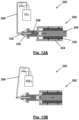
- Figs. 13A and 13B illustrate an gap control mechanism 320 for excluding any gap possibly existing in the CO 2 injection device.
- the soda machine 200 requires the injection of CO 2 from the CO 2 canister 260 to the carbonation tank 202.
- the pressure in the CO 2 canister 260 is high and therefore the power required for pushing the paintball 266 and release the CO 2 is very strong.
- a lever 264 may be used. However, the use of the lever 264 increases the required solenoid stroke.
- the gap control mechanism 320 closes the gaps between the mechanical structure parts between the solenoid 262 and the paintball 266 whenever the solenoid 262 is not activated, for example, when replacing a used CO 2 canister 260 by a new one.
- Figs. 13A and 13B show the gap control mechanism 320 in two positions “non-activated” ( Fig. 13A ) and “activated” ( Fig. 13B ).
- solenoid pin core 326 When the solenoid coil 322, which is held by a frame 324, is not activated, solenoid pin core 326 is pushed back (i.e. to the right in Fig. 13A ) by the closing force of the CO 2 paintball 266 pin which is transferred to the solenoid pin core 326 via the lever 264 and the spring 328. Should the CO 2 paintball 266 pin be closed, before the solenoid pin core 326 has reached its end position, the spring 328 further expands opening the clamping jaws 330 which are pivotably connected to solenoid pin core 326, thus releasing pin 332 which is articulated at the end of the lever 264. It should be noted that the force of the spring 328 is smaller than the closing force of the CO 2 paintball 266 pin.
- the solenoid core pin 326 moves forward (i.e. to the left in Fig. 13B ) and pushes the clamping jaws 330 into clamping engagement with the pin 332 in order to move the pin 332 together with solenoid pin core 326.
- Pin 332 pushes the lever arm 264, which in turn presses the paintball 266 in order to release the CO 2 gas.
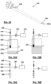
- Fig. 14 shows a perspective view of the liquid level sensor unit 340, not falling under the scope of the present claims.
- Figs. 15A and 15B show the arrangement of the liquid level sensor 342 in a situation, in which the liquid level is below the sensor height h ( Fig. 15A ), and in a situation, in which the liquid level is above the sensor height h ( Fig. 15B ) such that the liquid is in contact with the sensor tip.
- Figs. 16A and 16b show the equivalent electrical circuits corresponding to Figs. 15A and 15B , respectively.
- the liquid level sensors 342, 344 of the liquid sensor unit 340 are detecting the liquid height level in a new way based on the Ohm's low.
- Ohm's law states that the current flowing through a conductor between two points is directly proportional to the voltage across the two points.
- the sensor 342 proposed is based on an electrical circuit containing a power supply 346, a resistor 348, and a device 350 for detecting the voltage at a given point 352, i.e. to detect the voltage drop over the resistor 348.
- the voltage sensed at the given point 352 is similar to the value V of the power supply voltage.
- the sensor tip 342a is in contact with the liquid, and the liquid is grounded, for example by a grounded metal tank, a certain current will flow through the liquid and a drop in voltage will be sensed at the given point 352 due to the voltage drop over the resistor 348.
- the sensor unit 340 comprises a conductive sensor tip 342a connected to a power supply 346 via an electrically conductive line and resistor 348 of fixed resistance R.
- a voltage detector 350 connected to a microcontroller unit 354 is attached to line at the given point 352 for analyzing the results sensed.
- An isolating housing 356 protects the electrical line which connects between the sensor tip 342a and the power supply 346.
- the sensor tip 342a is positioned in the vessel 202 at a height h required to be detected.
- the liquid 358 is connected to ground via the tank 202.
- Fig. 15A and the corresponding electrical circuit shown in Fig. 16A represent a situation in which the sensor tip 342a is not in contact with the liquid. Accordingly, the switch 360 of the electrical circuit of Fig. 16A is open. As a consequence, there is no flow of current over the resistor 348, the voltage drop ⁇ V over the resistor 348 is 0, and the voltage sensed at point 352 is the voltage V provided by the power supply 346.
- Fig. 15B and the corresponding electrical circuit shown in Fig. 16B represent a situation in which the sensor tip 342a is in contact with the liquid, e.g. water.
- the liquid e.g. water.
- the switch 360 of the electrical circuit of Fig. 16B is closed.
- ⁇ V V ⁇ R / R + r
- V designating the voltage provided by the power supply 346
- R designating the resistance of the resistor 348
- r designating the resistance of the water 358.
- the resistance R of the resistor 348 is selected to be substantially equal to the resistance R of the water (R ⁇ r), the voltage drop ⁇ V over the resistor will be about half of the voltage V provided by the power supply 346 ( ⁇ V ⁇ 1 ⁇ 2 V).
- Fig. 17 shows a schematic view of a manifold 370, not falling under the scope of the present claims.
- the manifold 370 proposed intends to control and dispatch the chosen liquid to the faucet 112 and to hold as many components as required for the operation of the system 100. Since the number of liquids, which may be used, is large, the manifold 370 is flexible to be adopted for using a changing variety of liquids.
- the manifold 370 proposed is flexible to a wide variety of liquids, handling safety components, such as safety group, pressure sensor, pressure relief valve, and consumable parts, such as CO 2 canister, additive materials, filters, sterilizer UV lamp and the like.
- safety components such as safety group, pressure sensor, pressure relief valve, and consumable parts, such as CO 2 canister, additive materials, filters, sterilizer UV lamp and the like.
- the manifold 370 comprises a housing box 372, preferably made from mold-injected plastics, having with inlet and outlet pipes, internal liquid paths, controlled by solenoids assembled on the box in the right places, to manage the distribution of the liquids.
- the expandable manifold 370 consists of few boards, such as boards 374, 376, and 378 in Fig. 17 . Each of the boards may contain a few ingoing pipes 374a, 376a, and 378a and a few outgoing pipes 374b, 376b, and 378b controlled by solenoid valves, to control the flow of the liquids.
- a safety group 380 may be added when the system contains a boiler.
- the manifold 370 may include consumable parts like CO 2 cylinders 260, additive containers 382 for enriching the water, such as syrup, flavors drops, minerals, coffee, etc., water filter and water treatment device 384 such as UV light sterilizer.
- Fig. 18 shows possible locations for arranging a water sterilizing unit 390.
- Water sterilizing devices 392, 394 may be positioned either between tank 240, i.e. the source of the supplied water, and manifold 370 or alternatively between the manifold 370 and the faucet 112.
- Each of the water sterilizing units 392, 394 comprises a pipe and an internal UV light source to treat the water coming out of the tank 240.
- the pipe is integrated in the water-based liquid supply system 100 and turned on selectively when sterilizing is required.
- An alternative arrangement comprises a transparent pipe and an external UV light source.
- Fig. 19 shows a schematic view of a flavor unit 400, not falling under the scope of the present claims.
- the flavor unit 400 proposed provides the option to inject additives to the water-based liquid.
- additives may be water flavor, vitamins, minerals etc.
- the system may comprise a container 402 filled with any additive.
- the container 402 may be connected to the pipe 404 which is holding the water flow from the source, e.g. from the manifold 370, to the faucet 112.
- the connection includes a mixing injection chamber 406.
- the flavor unit 400 further includes the option to wash the pipe 408 connecting the container 402 to the mixing injection chamber 406.
- the pipe 408 may be connected to the drain 410, and by circulating the pump 412 in opposite direction the water-based liquid (for example boiling water) may be frowned from pipe 404 to the drain 410 through pipe 408 and clean it.
- a control unit 500 for controlling, in general, kitchen smart home appliances, such as the water-based liquid supply system 100 according to the present invention, a cooker 502, a hood 504, or other IOT devices 506, 508, such as a refrigerator, an oven, a microwave, a dish washer and other devices installed in the kitchen, but also other smart home appliances is disclosed.
- IOT devices 506, 508 such as a refrigerator, an oven, a microwave, a dish washer and other devices installed in the kitchen, but also other smart home appliances.
- the description will, only for the purpose of illustration, concentrate on the control of the water-based liquid supply system 100, the cooker 502 and the kitchen hood 504.
- the use of the control system 500 for controlling the home appliances, the such as the water-based liquid supply system 100, the cooker 502 and the hood 504, provides a wide range of capabilities.
- control system 500 combined with the water-based liquid supply system 100 provides the following advantages:
- the communication system 510 allows every sub-system to monitor and control every other sub-system, excluding intentionally prevented access due to safety, security and operational aspects.
- a sub-system may be provided as an IOT device, smartphone app, control panel, speech recognition device, cloud as well as devices through cloud.
- the system offers two optional structures.
- the control system 500 offers many operational options such as:
- Fig. 20A is a schematic indoor arrangement of the control system 500 and its communication system 510 for the kitchen appliances without a hub.
- Fig. 20B is a schematic indoor arrangement of the control system 500 and its communication system 510 for the kitchen appliances including a hub 516 and application control.
- Fig 20C is a schematic arrangement of the control system 500 and its communication system 510 for the kitchen appliances with outdoor communication.
- Fig. 20C represents a detailed chart including an indoor hub 516, a cloud connection 518, in particular for providing an outdoor virtual hub, and the smart mobile device 512, 520.
- Optional applications may be video camera devices control system, boot loader, speech recognition, indoor applications connected to the local hub by Bluetooth, and the local hub which is contact with the virtual hub in the cloud.
- the cloud option opens a wide range of applications, such as availability of data bases, both public and private applications and web personal assistance.
- the cloud web applications include dashboards service and store, white labelling, monitoring and alerts.
- Fig. 21 shows an example of the dashboard generated by the smartphone application to demonstrate the data collected on "water consumption” and "boiler temperature” from the system.
- control system 500 and its communication system 510 will be given.
- an upgradable control system 500 for IOT solution is provided, including optional utilization levels of the control system 500 of the IOT solution
- Utilization level (1) refers to the applicant's kitchen devices, which may be controlled by the applicant's proprietary control units. Control units may control/display/communicate with one or more kitchen device(s) simultaneously, and may enable direct connection among kitchen devices themselves. The connection of the control units to the kitchen devices may be wired or wireless (IR, RF (i.e. ZigBee/BLE/Wi-Fi/))
- the user may prefer to operate his kitchen devices through his smartphone 520. All of the applicant's devices support the connection to wireless smartphone communication, and give the user a very user-friendly, feature-rich real-time opportunity to control his kitchen devices.
- the applicant's smartphone applications can connect to the applicant's kitchen devices indoors both, directly or indirectly through a hub 516. It can also connect outdoors through the applicant's cloud infrastructure.
- the applicant's cloud solution is not just limited to smartphone control, it also enables
- Utilization level (5) internet (cloud) display / alert / services:
- the cloud connectivity may be bidirectional and used not only for control (incoming communication), it enables also outgoing communication for the following purposes:
Landscapes
- Life Sciences & Earth Sciences (AREA)
- Engineering & Computer Science (AREA)
- Health & Medical Sciences (AREA)
- Water Supply & Treatment (AREA)
- Hydrology & Water Resources (AREA)
- Public Health (AREA)
- Chemical & Material Sciences (AREA)
- Organic Chemistry (AREA)
- Environmental & Geological Engineering (AREA)
- Physics & Mathematics (AREA)
- Polymers & Plastics (AREA)
- Thermal Sciences (AREA)
- Toxicology (AREA)
- General Health & Medical Sciences (AREA)
- Animal Behavior & Ethology (AREA)
- Epidemiology (AREA)
- Food Science & Technology (AREA)
- Medicinal Chemistry (AREA)
- Nutrition Science (AREA)
- Veterinary Medicine (AREA)
- Fluid Mechanics (AREA)
- General Physics & Mathematics (AREA)
- Chemical Kinetics & Catalysis (AREA)
- Devices For Dispensing Beverages (AREA)
- Pipeline Systems (AREA)
- Fluid-Driven Valves (AREA)
- Domestic Plumbing Installations (AREA)
Claims (4)
- Flüssigkeit-Liefersystem (100) zum Zubereiten und Abgeben von wasserbasierten Flüssigkeiten, wie beispielsweise heißes Wasser, gekühltes und gesprudeltes Wasser, heiße und kalte Getränke, gesprudelt oder nicht-gesprudelt, bei einer gewünschten Temperatur und mit wenigstens einem Zusatzstoff bei einer gewünschten Konzentration auf Anfrage, wobei das Flüssigkeit-Liefersystem umfasst:- eine Wasserzufuhr, umfassend wenigstens einen Wassertank (102) und/oder eine Verbindung (130, 132) zu einer Haupt-Wasserleitung,- wenigstens einen Hahn (112), welcher einen Auslass zum Abgeben der zubereiteten wasserbasierten Flüssigkeit aufweist und umfasst:∘ eine Basiseinheit (134), welche an einer Arbeitsfläche (136) mittels einer Mutter (150) und einer Basisschulter (152) fixierbar ist; und∘ einen Schwenkausgießer (140), welcher mit einer fixierten Basis (154) verbunden ist und einen Belüfter (142) umfasst, und- einen Wasserfilter, welcher dazu eingerichtet ist, Wasser von der Wasserzufuhr zu filtern,- einen Wasserboiler, welcher dazu eingerichtet ist, Wasser von der Wasserzufuhr auf eine vorbestimmte Temperatur zu erwärmen, und/oder einen Wasserkühler (302), welcher dazu eingerichtet ist, Wasser von der Wasserzufuhr auf eine vorbestimmte Temperatur zu kühlen, und- eine Sodamaschine (200), welche dazu eingerichtet ist, Wasser von der Wasserzufuhr auf eine vorbestimmte CO2-Konzentration zu sprudeln,wobei das System (100) ferner umfasst:- einen Zusatzstoff-Mischer, welcher dazu eingerichtet ist, den wenigstens einen Zusatzstoff, welcher von wenigstens einem Zusatzstoff-Behälter (126) geliefert wird, bei einer vorbestimmten Konzentration zu Wasser von der Wasserzufuhr beizumischen, wobei der Zusatzstoff-Mischer eine Pumpe (128) zum Liefern eines vorbestimmten Zusatzstoffs oder mehrerer Zusatzstoffe von dem jeweiligen Zusatzstoff-Behälter (126) umfasst;- ein Leitungssystem, welches die Wasserzufuhr, den Hahn (112), den Wasserfilter und den Wasserboiler und/oder den Wasserkühler, die Sodamaschine (200) und den Zusatzstoff-Mischer verbindet, welche in dem Flüssigkeit-Liefersystem installiert sind, und- ein Kommunikation- und Steuersystem (500), welches dazu eingerichtet ist, mit einem Benutzer zu kommunizieren und die Zubereitung und das Abgeben der wasserbasierten Flüssigkeit auf Grundlage einer Kommunikation mit dem Benutzer zu steuern.
- Flüssigkeit-Liefersystem nach Anspruch 1,
wobei wenigstens ein Teil des Leitungssystems dazu eingerichtet ist, trockengelegt und/oder mit einer Reinigungsflüssigkeit, vorzugsweise kochendem Wasser, regelmäßig oder auf Anfrage oder zu vorbestimmten Gelegenheiten gespült zu werden, wie beispielsweise einer Änderung in der Art von wasserbasierter Flüssigkeit, welche von dem Benutzer ausgewählt wird. - Flüssigkeit-Liefersystem nach Anspruch 1 oder 2,
wobei mehrere Komponenten des Flüssigkeit-Liefersystems (100), wie beispielsweise der Hahn (112), die Wasserzufuhr, das Leitungssystem oder Teile des Leitungssystems intelligente Anlagen sind, welche dazu eingerichtet sind, miteinander und/oder mit dem Benutzer und/oder der Außenwelt mittels des Kommunikation- und Steuersystems (500) zu kommunizieren, und wobei das Kommunikation- und Steuersystem (500) dazu eingerichtet ist, dass darauf von dem Benutzer mittels eines lokalen proprietären Steuer-Panels und/oder mittels einer mobilen Vorrichtung, wie beispielsweise einem Smartphone oder einem Tablet-Computer mit einer geeigneten mobilen Anwendung, zugegriffen wird, und wobei das Kommunikation- und Steuersystem (500) derart eingerichtet ist, dass von dem Benutzer direkt und/oder mittels einem lokalen Hub oder mittels einer Cloud-Kommunikation durch das Internet darauf zugegriffen wird. - Flüssigkeit-Liefersystem nach einem der vorhergehenden Ansprüche,
wobei das Flüssigkeit-Liefersystem (100) dazu eingerichtet ist, eine vorbestimmte Anzahl von unterschiedlichen Arten von wasserbasierten Flüssigkeiten zuzubereiten, wobei jede dieser unterschiedlichen Arten von wasserbasierten Flüssigkeiten einer spezifischen vorbestimmten Anzeige zugeordnet ist, z.B. einer spezifischen vorbestimmten Farbe, und wobei das Flüssigkeit-Liefersystem (100), vorzugsweise der Hahn (112), eine Anzeigevorrichtung umfasst, welche dazu eingerichtet ist, die spezifische vorbestimmte Anzeige anzuzeigen, welche der Art von wasserbasierter Flüssigkeit zugeordnet ist, welche momentan ausgewählt, zubereitet oder abgegeben wird.
Priority Applications (3)
| Application Number | Priority Date | Filing Date | Title |
|---|---|---|---|
| DK20190219.4T DK3760795T3 (da) | 2018-03-02 | 2018-03-05 | Væskeforsyningssystem |
| EP20190219.4A EP3760795B1 (de) | 2018-03-02 | 2018-03-05 | System zur flüssigkeitsversorgung |
| US16/291,110 US11772952B2 (en) | 2018-03-02 | 2019-03-04 | Water-based liquid supply system |
Applications Claiming Priority (1)
| Application Number | Priority Date | Filing Date | Title |
|---|---|---|---|
| EP18159765 | 2018-03-02 |
Related Child Applications (2)
| Application Number | Title | Priority Date | Filing Date |
|---|---|---|---|
| EP20190219.4A Division EP3760795B1 (de) | 2018-03-02 | 2018-03-05 | System zur flüssigkeitsversorgung |
| EP20190219.4A Division-Into EP3760795B1 (de) | 2018-03-02 | 2018-03-05 | System zur flüssigkeitsversorgung |
Publications (4)
| Publication Number | Publication Date |
|---|---|
| EP3533937A2 EP3533937A2 (de) | 2019-09-04 |
| EP3533937A3 EP3533937A3 (de) | 2019-11-13 |
| EP3533937B1 true EP3533937B1 (de) | 2025-06-18 |
| EP3533937C0 EP3533937C0 (de) | 2025-06-18 |
Family
ID=61563195
Family Applications (2)
| Application Number | Title | Priority Date | Filing Date |
|---|---|---|---|
| EP18159914.3A Active EP3533937B1 (de) | 2018-03-02 | 2018-03-05 | Versorgungssystem der wasserbasierenden flüssigkeiten |
| EP20190219.4A Active EP3760795B1 (de) | 2018-03-02 | 2018-03-05 | System zur flüssigkeitsversorgung |
Family Applications After (1)
| Application Number | Title | Priority Date | Filing Date |
|---|---|---|---|
| EP20190219.4A Active EP3760795B1 (de) | 2018-03-02 | 2018-03-05 | System zur flüssigkeitsversorgung |
Country Status (6)
| Country | Link |
|---|---|
| US (1) | US11772952B2 (de) |
| EP (2) | EP3533937B1 (de) |
| DK (1) | DK3760795T3 (de) |
| ES (1) | ES2947169T3 (de) |
| FI (1) | FI3760795T3 (de) |
| PT (1) | PT3760795T (de) |
Families Citing this family (55)
| Publication number | Priority date | Publication date | Assignee | Title |
|---|---|---|---|---|
| US10988364B2 (en) * | 2017-05-09 | 2021-04-27 | Leonard Fountain Specialties, Inc. | Carbonation tank assembly |
| US12264462B2 (en) | 2018-08-07 | 2025-04-01 | Delta Faucet Company | Liquid control apparatus and related methods |
| CA3116689A1 (en) * | 2018-10-15 | 2020-04-23 | Rich Products Corporation | Food product dispenser with temperature control |
| CN109596190B (zh) * | 2018-12-17 | 2020-07-24 | 中国十七冶集团有限公司 | 一种基坑降水井水位测量装置及实施方法 |
| DE102019101989A1 (de) * | 2019-01-28 | 2020-07-30 | Grohe Ag | Vorrichtung und Verfahren zur Herstellung einer karbonisierten Flüssigkeit mit einer Mehrzahl von CO2-Behältern |
| DE102019104226A1 (de) * | 2019-02-20 | 2020-08-20 | Grohe Ag | Verfahren und Vorrichtung zum Entkalken von Wasser |
| GB2582949A (en) * | 2019-04-10 | 2020-10-14 | Marco Beverage Systems Ltd | A beverage dispense system |
| US11479455B2 (en) | 2019-05-17 | 2022-10-25 | Pepsico, Inc. | Water dispensing station |
| EP3834622A1 (de) * | 2019-12-11 | 2021-06-16 | Unito Smart Technologies Limited | Karbonisierungsverfahren |
| CN111142586B (zh) * | 2020-01-03 | 2023-06-27 | 湖南农业大学 | 一种雾培种植装置的控制系统 |
| DE102020108555A1 (de) | 2020-03-27 | 2021-09-30 | Grohe Ag | Auslaufelement für eine Trinkwasserzapfanlage |
| DE102020108554A1 (de) * | 2020-03-27 | 2021-09-30 | Grohe Ag | Spenderkartusche |
| US11007292B1 (en) | 2020-05-01 | 2021-05-18 | Uv Innovators, Llc | Automatic power compensation in ultraviolet (UV) light emission device, and related methods of use, particularly suited for decontamination |
| WO2021257008A1 (en) * | 2020-06-16 | 2021-12-23 | Gül Pres Döküm Sanayi Anonim Sirketi | New generation, uv sterilized, microcomputer controlled water and soap armature, which has single sensor and single center output, and its working system |
| WO2022016047A1 (en) | 2020-07-17 | 2022-01-20 | Sloan Valve Company | Light ring for plumbing fixtures |
| DE102020214549A1 (de) * | 2020-11-18 | 2022-05-19 | Blanco Gmbh + Co Kg | Sanitärarmatur sowie Sanitärsystem |
| DE102020130426A1 (de) * | 2020-11-18 | 2022-05-19 | Grohe Ag | Vorrichtung und Verfahren zur Herstellung einer karbonisierten Flüssigkeit |
| KR20220120368A (ko) * | 2021-02-23 | 2022-08-30 | 삼성전자주식회사 | 출수 유닛 및 이를 포함하는 정수기 |
| WO2022192345A1 (en) * | 2021-03-09 | 2022-09-15 | Rachel Dombrowsky | Mobile washing station |
| DE102021108027A1 (de) * | 2021-03-30 | 2022-10-06 | Grohe Ag | System umfassend eine Wasserinstallation und ein Modul zur Bedienung |
| US20220340406A1 (en) * | 2021-04-23 | 2022-10-27 | Elkay Manufacturing Company | Thermoelectric cooling and compact carbonation system |
| CN113598999B (zh) * | 2021-08-10 | 2022-07-01 | 深圳市柏斯曼电子科技股份有限公司 | 一种冲牙器及其控制方法 |
| EP4151587B1 (de) | 2021-09-16 | 2025-11-26 | Unito Smart Technologies Limited | Getränkemischvorrichtung und mischbatteriesystem |
| DE102021212428A1 (de) | 2021-11-04 | 2023-05-04 | Blanco Gmbh + Co Kg | Sanitärarmatur zur Ausgabe aufbereiteter Flüssigkeiten |
| DE102021212427A1 (de) * | 2021-11-04 | 2023-05-04 | Blanco Gmbh + Co Kg | Sanitärarmatur zur Ausgabe aufbereiteter Flüssigkeiten |
| US12258258B2 (en) * | 2021-11-19 | 2025-03-25 | 7-Eleven, Inc. | Beverage dispenser fluid level sensor |
| US11753293B2 (en) | 2021-12-22 | 2023-09-12 | Kraus Usa Plumbing Llc | Fluid dispensing systems and methods |
| DE102022106836A1 (de) | 2022-03-23 | 2023-09-28 | Grohe Ag | Vorrichtung und Verfahren zur Herstellung einer karbonisierten Flüssigkeit |
| DE102022106835A1 (de) * | 2022-03-23 | 2023-09-28 | Grohe Ag | Sanitärarmatur |
| DE102022108203A1 (de) * | 2022-04-05 | 2023-10-05 | Grohe Ag | Vorrichtung und Verfahren zum Versetzen einer Flüssigkeit mit einem Additiv |
| EP4265858A1 (de) * | 2022-04-22 | 2023-10-25 | Unito Smart Technologies Limited | Wasserhahnsystem |
| CA3253404A1 (en) | 2022-05-13 | 2023-11-16 | Sharkninja Operating Llc | AGITATOR FOR CARBONATION SYSTEM |
| US11751585B1 (en) | 2022-05-13 | 2023-09-12 | Sharkninja Operating Llc | Flavored beverage carbonation system |
| US12213617B2 (en) | 2022-05-13 | 2025-02-04 | Sharkninja Operating Llc | Flavored beverage carbonation process |
| US11647860B1 (en) | 2022-05-13 | 2023-05-16 | Sharkninja Operating Llc | Flavored beverage carbonation system |
| US12096880B2 (en) | 2022-05-13 | 2024-09-24 | Sharkninja Operating Llc | Flavorant for beverage carbonation system |
| CN115078659A (zh) * | 2022-08-05 | 2022-09-20 | 成都大欧建筑装饰工程有限公司 | 建筑给排水合理性监测分析评价方法、系统及存储介质 |
| US12005404B2 (en) | 2022-08-22 | 2024-06-11 | Sharkninja Operating Llc | Beverage carbonation system flow control |
| US12539500B2 (en) | 2022-08-31 | 2026-02-03 | Sharkninja Operating Llc | Additive containers |
| CN218188979U (zh) * | 2022-09-27 | 2023-01-03 | 沛乐迪(厦门)卫浴有限公司 | 微气泡发生容器及出水装置 |
| US11745996B1 (en) | 2022-11-17 | 2023-09-05 | Sharkninja Operating Llc | Ingredient containers for use with beverage dispensers |
| US12103840B2 (en) | 2022-11-17 | 2024-10-01 | Sharkninja Operating Llc | Ingredient container with sealing valve |
| US11738988B1 (en) | 2022-11-17 | 2023-08-29 | Sharkninja Operating Llc | Ingredient container valve control |
| US11634314B1 (en) | 2022-11-17 | 2023-04-25 | Sharkninja Operating Llc | Dosing accuracy |
| US12084334B2 (en) | 2022-11-17 | 2024-09-10 | Sharkninja Operating Llc | Ingredient container |
| USD1091308S1 (en) | 2022-12-23 | 2025-09-02 | Sharkninja Operating Llc | Ingredient container |
| USD1092208S1 (en) | 2022-12-23 | 2025-09-09 | Sharkninja Operating Llc | Cap of ingredient container |
| DE102023102162A1 (de) * | 2023-01-30 | 2024-08-01 | Grohe Ag | Vorrichtung zum Karbonisieren einer Flüssigkeit |
| US11925287B1 (en) | 2023-03-22 | 2024-03-12 | Sharkninja Operating Llc | Additive container with inlet tube |
| US12116257B1 (en) | 2023-03-22 | 2024-10-15 | Sharkninja Operating Llc | Adapter for beverage dispenser |
| US11871867B1 (en) | 2023-03-22 | 2024-01-16 | Sharkninja Operating Llc | Additive container with bottom cover |
| US12005408B1 (en) | 2023-04-14 | 2024-06-11 | Sharkninja Operating Llc | Mixing funnel |
| US12554299B2 (en) | 2023-04-24 | 2026-02-17 | Delta Faucet Company | Plumbing fixture with power and communication system |
| WO2024254837A1 (en) | 2023-06-16 | 2024-12-19 | Sharkninja Operating Llc | Carbonation mixing nozzles |
| DE102024119206A1 (de) * | 2024-07-05 | 2026-01-08 | Grohe Ag | Vorrichtung für eine Sanitärarmatur, Sanitärarmatur mit einer solchen Vorrichtung und Verfahren zum Betrieb einer Vorrichtung für eine Sanitärarmatur |
Citations (1)
| Publication number | Priority date | Publication date | Assignee | Title |
|---|---|---|---|---|
| WO2016040986A1 (en) * | 2014-09-16 | 2016-03-24 | Li Jun Xia | A fluid dispensing system, a system for processing waste material and a fluid monitoring system |
Family Cites Families (31)
| Publication number | Priority date | Publication date | Assignee | Title |
|---|---|---|---|---|
| US4615466A (en) * | 1984-02-24 | 1986-10-07 | The Coca-Cola Company | Beverage dispenser system convertable between gravity and pressure |
| JPH0789075B2 (ja) | 1987-02-10 | 1995-09-27 | 松下電器産業株式会社 | 圧電式水位検知装置 |
| US5000357A (en) * | 1987-10-13 | 1991-03-19 | Abc/Sebrn Tech Corp. Inc. | Soft drink dispenser |
| US4903862A (en) * | 1987-10-13 | 1990-02-27 | Abc/Sebrn Tech. Corp., Inc. | Soft drink dispenser |
| US5033645A (en) * | 1987-10-13 | 1991-07-23 | Abc/Sebrn Tech Corp. | Carbonation system for soft drink dispenser |
| US4909047A (en) * | 1988-02-16 | 1990-03-20 | Remcor Products Company | Beverage dispensing system |
| GB8926245D0 (en) * | 1989-11-21 | 1990-01-10 | Perrin Robert B | Water tap |
| US5697248A (en) | 1991-07-25 | 1997-12-16 | The Whitaker Corporation | Liquid level sensor |
| GB2287932B (en) * | 1994-03-29 | 1997-11-12 | Guinness Brewing Worldwide | A beverage dispensing system |
| US5706661A (en) * | 1995-09-29 | 1998-01-13 | Frank; Jimmy I. | Apparatus and method for controlling the consistency and quality of a frozen carbonated beverage product |
| US6216913B1 (en) | 1996-11-08 | 2001-04-17 | S.O.B. Partnership | Self-contained pneumatic beverage dispensing system |
| JPH10300559A (ja) | 1997-04-24 | 1998-11-13 | Asahi Organic Chem Ind Co Ltd | 水位センサー |
| GB2332154B (en) * | 1997-11-29 | 2001-08-29 | Imi Cornelius | Provision of carbonated beverages |
| US6684648B2 (en) * | 2000-07-26 | 2004-02-03 | Fakieh Research & Development Center | Apparatus for the production of freshwater from extremely hot and humid air |
| KR100535680B1 (ko) | 2001-07-13 | 2005-12-09 | 삼성전자주식회사 | 수위센서 |
| WO2010056486A2 (en) * | 2008-11-17 | 2010-05-20 | EcoloBlue, Inc. | Apparatus and methods for creating sparkling water from the atmosphere |
| US8442674B2 (en) * | 2010-02-05 | 2013-05-14 | Ecowell | Container-less custom beverage vending invention |
| JP2011215144A (ja) | 2010-03-15 | 2011-10-27 | Ran Techno:Kk | 水位センサ |
| ITMO20110035A1 (it) * | 2011-02-17 | 2012-08-18 | Roberto Marchetti | Apparecchiatura per l'erogazione di acqua e soda |
| WO2013036564A2 (en) * | 2011-09-09 | 2013-03-14 | Fountain Master, Llc | Beverage maker |
| ITMI20121479A1 (it) | 2012-09-05 | 2014-03-06 | Sparkling Drink Systems Innovation Ct Ltd | Macchina per l'erogazione di acqua. |
| RU2629868C2 (ru) | 2012-09-13 | 2017-09-04 | Страусс Уотер Лтд. | Дозирующее устройство для напитков с системой газирования |
| CN102984039B (zh) | 2012-11-06 | 2016-03-23 | 鸿富锦精密工业(深圳)有限公司 | 智能网关、智能家居系统及家电设备的智能控制方法 |
| US20140158638A1 (en) * | 2012-12-12 | 2014-06-12 | Pristinehydro Development, Inc. | Water filtration and treatment systems and methods |
| US9409758B2 (en) | 2013-07-10 | 2016-08-09 | As Ip Holdco, Llc | Faucet-integrated carbonation systems and methods |
| WO2015008249A1 (en) | 2013-07-18 | 2015-01-22 | Sodastream Industries Ltd. | Device for dispensing carbonated water |
| US20150329346A1 (en) * | 2014-05-16 | 2015-11-19 | Rebot R&D, LLC | Systems for monitoring and displaying information for beverage dispensing systems |
| CN105573142A (zh) | 2014-10-15 | 2016-05-11 | 珠海格力电器股份有限公司 | 智能家居控制系统 |
| US10111554B2 (en) * | 2015-03-20 | 2018-10-30 | Meltz, LLC | Systems for and methods of controlled liquid food or beverage product creation |
| ES2883719T3 (es) | 2015-04-24 | 2021-12-09 | Emerson Electric Co | Unidad de control para aparatos debajo del fregadero |
| US20170360243A1 (en) * | 2016-06-17 | 2017-12-21 | Crowne Coffee Co., Llc | Beverage dispensing system and method |
-
2018
- 2018-03-05 EP EP18159914.3A patent/EP3533937B1/de active Active
- 2018-03-05 EP EP20190219.4A patent/EP3760795B1/de active Active
- 2018-03-05 DK DK20190219.4T patent/DK3760795T3/da active
- 2018-03-05 ES ES20190219T patent/ES2947169T3/es active Active
- 2018-03-05 FI FIEP20190219.4T patent/FI3760795T3/fi active
- 2018-03-05 PT PT201902194T patent/PT3760795T/pt unknown
-
2019
- 2019-03-04 US US16/291,110 patent/US11772952B2/en active Active
Patent Citations (1)
| Publication number | Priority date | Publication date | Assignee | Title |
|---|---|---|---|---|
| WO2016040986A1 (en) * | 2014-09-16 | 2016-03-24 | Li Jun Xia | A fluid dispensing system, a system for processing waste material and a fluid monitoring system |
Also Published As
| Publication number | Publication date |
|---|---|
| EP3760795B1 (de) | 2023-04-05 |
| ES2947169T3 (es) | 2023-08-02 |
| EP3533937A3 (de) | 2019-11-13 |
| PT3760795T (pt) | 2023-06-21 |
| FI3760795T3 (fi) | 2023-06-14 |
| US11772952B2 (en) | 2023-10-03 |
| EP3533937C0 (de) | 2025-06-18 |
| EP3760795A1 (de) | 2021-01-06 |
| EP3533937A2 (de) | 2019-09-04 |
| DK3760795T3 (da) | 2023-06-06 |
| US20190270630A1 (en) | 2019-09-05 |
Similar Documents
| Publication | Publication Date | Title |
|---|---|---|
| EP3533937B1 (de) | Versorgungssystem der wasserbasierenden flüssigkeiten | |
| US12441597B2 (en) | Beverage dispenser | |
| US12122654B2 (en) | Water dispensing station | |
| US12031767B2 (en) | Free-standing ice or beverage dispensing appliance | |
| US5285718A (en) | Combination beverage brewer with cold water supply | |
| US10919752B2 (en) | Refrigerator with carbonated drink spout | |
| US6871675B1 (en) | Countertop water dispenser | |
| US8377292B2 (en) | Water filter and dispenser system | |
| US6073539A (en) | Combination bottled water and coffee dispenser | |
| CN101918323B (zh) | 水分配器 | |
| CN115175869A (zh) | 饮料设备和方法 | |
| US6483119B1 (en) | Ultraviolet treatment for liquid dispensing unit | |
| RU2568562C2 (ru) | Система для дозирования добавки в поток жидкости | |
| US12304799B2 (en) | Beverage-dispensing appliance having a chilled carbonator | |
| RU2241924C2 (ru) | Охдаждающее устройство | |
| JP2025509402A (ja) | 一体型の水処理及び着脱可能なウォーターリザーバを備えた炭酸化装置 | |
| JP2011073736A (ja) | 加熱殺菌のできるディスペンサ | |
| US20260042073A1 (en) | Beverage systems, devices, and methods | |
| WO2019169485A1 (en) | Beverage distribution apparatus and method for beverage distribution using same | |
| US20260042657A1 (en) | Systems, devices, and methods for portioned beverage preparation | |
| US20260042653A1 (en) | Systems, devices, and methods for multi-stage beverage preparation | |
| US20260042655A1 (en) | Beverage systems, devices, and methods with cleaning features | |
| WO2026035259A1 (en) | Beverage systems, devices, and methods | |
| WO2026035263A1 (en) | Systems, devices, and methods for multi-stage beverage preparation | |
| WO2026035261A1 (en) | Systems, devices, and methods for portioned beverage preparation |
Legal Events
| Date | Code | Title | Description |
|---|---|---|---|
| PUAI | Public reference made under article 153(3) epc to a published international application that has entered the european phase |
Free format text: ORIGINAL CODE: 0009012 |
|
| STAA | Information on the status of an ep patent application or granted ep patent |
Free format text: STATUS: THE APPLICATION HAS BEEN PUBLISHED |
|
| AK | Designated contracting states |
Kind code of ref document: A2 Designated state(s): AL AT BE BG CH CY CZ DE DK EE ES FI FR GB GR HR HU IE IS IT LI LT LU LV MC MK MT NL NO PL PT RO RS SE SI SK SM TR |
|
| AX | Request for extension of the european patent |
Extension state: BA ME |
|
| PUAL | Search report despatched |
Free format text: ORIGINAL CODE: 0009013 |
|
| AK | Designated contracting states |
Kind code of ref document: A3 Designated state(s): AL AT BE BG CH CY CZ DE DK EE ES FI FR GB GR HR HU IE IS IT LI LT LU LV MC MK MT NL NO PL PT RO RS SE SI SK SM TR |
|
| AX | Request for extension of the european patent |
Extension state: BA ME |
|
| RIC1 | Information provided on ipc code assigned before grant |
Ipc: E03C 1/02 20060101AFI20191008BHEP Ipc: E03C 1/04 20060101ALI20191008BHEP Ipc: E03C 1/044 20060101ALI20191008BHEP Ipc: E03C 1/05 20060101ALI20191008BHEP Ipc: B67D 1/00 20060101ALI20191008BHEP |
|
| STAA | Information on the status of an ep patent application or granted ep patent |
Free format text: STATUS: REQUEST FOR EXAMINATION WAS MADE |
|
| 17P | Request for examination filed |
Effective date: 20200507 |
|
| RBV | Designated contracting states (corrected) |
Designated state(s): AL AT BE BG CH CY CZ DE DK EE ES FI FR GB GR HR HU IE IS IT LI LT LU LV MC MK MT NL NO PL PT RO RS SE SI SK SM TR |
|
| STAA | Information on the status of an ep patent application or granted ep patent |
Free format text: STATUS: EXAMINATION IS IN PROGRESS |
|
| 17Q | First examination report despatched |
Effective date: 20210629 |
|
| RAP3 | Party data changed (applicant data changed or rights of an application transferred) |
Owner name: UNITO SMART TECHNOLOGIES LIMITED |
|
| RIN1 | Information on inventor provided before grant (corrected) |
Inventor name: DAHAN, ABRAHAM Inventor name: DAHAN, YUVAL-YONI |
|
| GRAP | Despatch of communication of intention to grant a patent |
Free format text: ORIGINAL CODE: EPIDOSNIGR1 |
|
| STAA | Information on the status of an ep patent application or granted ep patent |
Free format text: STATUS: GRANT OF PATENT IS INTENDED |
|
| INTG | Intention to grant announced |
Effective date: 20250117 |
|
| GRAS | Grant fee paid |
Free format text: ORIGINAL CODE: EPIDOSNIGR3 |
|
| GRAA | (expected) grant |
Free format text: ORIGINAL CODE: 0009210 |
|
| STAA | Information on the status of an ep patent application or granted ep patent |
Free format text: STATUS: THE PATENT HAS BEEN GRANTED |
|
| AK | Designated contracting states |
Kind code of ref document: B1 Designated state(s): AL AT BE BG CH CY CZ DE DK EE ES FI FR GB GR HR HU IE IS IT LI LT LU LV MC MK MT NL NO PL PT RO RS SE SI SK SM TR |
|
| REG | Reference to a national code |
Ref country code: GB Ref legal event code: FG4D |
|
| REG | Reference to a national code |
Ref country code: CH Ref legal event code: EP |
|
| REG | Reference to a national code |
Ref country code: DE Ref legal event code: R096 Ref document number: 602018082618 Country of ref document: DE |
|
| REG | Reference to a national code |
Ref country code: CH Ref legal event code: EP |
|
| REG | Reference to a national code |
Ref country code: IE Ref legal event code: FG4D |
|
| U01 | Request for unitary effect filed |
Effective date: 20250618 |
|
| U07 | Unitary effect registered |
Designated state(s): AT BE BG DE DK EE FI FR IT LT LU LV MT NL PT RO SE SI Effective date: 20250626 |
|
| PG25 | Lapsed in a contracting state [announced via postgrant information from national office to epo] |
Ref country code: GR Free format text: LAPSE BECAUSE OF FAILURE TO SUBMIT A TRANSLATION OF THE DESCRIPTION OR TO PAY THE FEE WITHIN THE PRESCRIBED TIME-LIMIT Effective date: 20250919 Ref country code: NO Free format text: LAPSE BECAUSE OF FAILURE TO SUBMIT A TRANSLATION OF THE DESCRIPTION OR TO PAY THE FEE WITHIN THE PRESCRIBED TIME-LIMIT Effective date: 20250918 |
|
| PG25 | Lapsed in a contracting state [announced via postgrant information from national office to epo] |
Ref country code: HR Free format text: LAPSE BECAUSE OF FAILURE TO SUBMIT A TRANSLATION OF THE DESCRIPTION OR TO PAY THE FEE WITHIN THE PRESCRIBED TIME-LIMIT Effective date: 20250618 |
|
| PG25 | Lapsed in a contracting state [announced via postgrant information from national office to epo] |
Ref country code: RS Free format text: LAPSE BECAUSE OF FAILURE TO SUBMIT A TRANSLATION OF THE DESCRIPTION OR TO PAY THE FEE WITHIN THE PRESCRIBED TIME-LIMIT Effective date: 20250918 |
|
| PG25 | Lapsed in a contracting state [announced via postgrant information from national office to epo] |
Ref country code: IS Free format text: LAPSE BECAUSE OF FAILURE TO SUBMIT A TRANSLATION OF THE DESCRIPTION OR TO PAY THE FEE WITHIN THE PRESCRIBED TIME-LIMIT Effective date: 20251018 |
|
| PG25 | Lapsed in a contracting state [announced via postgrant information from national office to epo] |
Ref country code: SM Free format text: LAPSE BECAUSE OF FAILURE TO SUBMIT A TRANSLATION OF THE DESCRIPTION OR TO PAY THE FEE WITHIN THE PRESCRIBED TIME-LIMIT Effective date: 20250618 |
|
| PG25 | Lapsed in a contracting state [announced via postgrant information from national office to epo] |
Ref country code: CZ Free format text: LAPSE BECAUSE OF FAILURE TO SUBMIT A TRANSLATION OF THE DESCRIPTION OR TO PAY THE FEE WITHIN THE PRESCRIBED TIME-LIMIT Effective date: 20250618 |
|
| PG25 | Lapsed in a contracting state [announced via postgrant information from national office to epo] |
Ref country code: PL Free format text: LAPSE BECAUSE OF FAILURE TO SUBMIT A TRANSLATION OF THE DESCRIPTION OR TO PAY THE FEE WITHIN THE PRESCRIBED TIME-LIMIT Effective date: 20250618 |
|
| PG25 | Lapsed in a contracting state [announced via postgrant information from national office to epo] |
Ref country code: SK Free format text: LAPSE BECAUSE OF FAILURE TO SUBMIT A TRANSLATION OF THE DESCRIPTION OR TO PAY THE FEE WITHIN THE PRESCRIBED TIME-LIMIT Effective date: 20250618 |
|
| PG25 | Lapsed in a contracting state [announced via postgrant information from national office to epo] |
Ref country code: ES Free format text: LAPSE BECAUSE OF FAILURE TO SUBMIT A TRANSLATION OF THE DESCRIPTION OR TO PAY THE FEE WITHIN THE PRESCRIBED TIME-LIMIT Effective date: 20250618 |