EP3533362B1 - Hilfsvorrichtung zum an- und ausziehen von kompressionssocken - Google Patents
Hilfsvorrichtung zum an- und ausziehen von kompressionssocken Download PDFInfo
- Publication number
- EP3533362B1 EP3533362B1 EP19160016.2A EP19160016A EP3533362B1 EP 3533362 B1 EP3533362 B1 EP 3533362B1 EP 19160016 A EP19160016 A EP 19160016A EP 3533362 B1 EP3533362 B1 EP 3533362B1
- Authority
- EP
- European Patent Office
- Prior art keywords
- stocking
- assist device
- spring element
- support poles
- compression stocking
- Prior art date
- Legal status (The legal status is an assumption and is not a legal conclusion. Google has not performed a legal analysis and makes no representation as to the accuracy of the status listed.)
- Active
Links
- 230000006835 compression Effects 0.000 title claims description 82
- 238000007906 compression Methods 0.000 title claims description 82
- 210000002414 leg Anatomy 0.000 claims description 15
- 238000000034 method Methods 0.000 claims description 9
- 210000003127 knee Anatomy 0.000 claims description 4
- 210000002683 foot Anatomy 0.000 description 16
- 238000005452 bending Methods 0.000 description 14
- 210000001699 lower leg Anatomy 0.000 description 7
- 239000000463 material Substances 0.000 description 7
- 230000002093 peripheral effect Effects 0.000 description 6
- 229920001971 elastomer Polymers 0.000 description 5
- 230000033001 locomotion Effects 0.000 description 5
- 230000001225 therapeutic effect Effects 0.000 description 5
- 125000006850 spacer group Chemical group 0.000 description 4
- 210000003371 toe Anatomy 0.000 description 4
- XAGFODPZIPBFFR-UHFFFAOYSA-N aluminium Chemical compound [Al] XAGFODPZIPBFFR-UHFFFAOYSA-N 0.000 description 3
- 229910052782 aluminium Inorganic materials 0.000 description 3
- 239000004411 aluminium Substances 0.000 description 3
- 238000001746 injection moulding Methods 0.000 description 3
- 238000003780 insertion Methods 0.000 description 3
- 230000037431 insertion Effects 0.000 description 3
- 230000000284 resting effect Effects 0.000 description 2
- 210000002303 tibia Anatomy 0.000 description 2
- 229920002430 Fibre-reinforced plastic Polymers 0.000 description 1
- 229910000831 Steel Inorganic materials 0.000 description 1
- 206010046996 Varicose vein Diseases 0.000 description 1
- 238000004026 adhesive bonding Methods 0.000 description 1
- 210000003423 ankle Anatomy 0.000 description 1
- 238000007743 anodising Methods 0.000 description 1
- 238000000748 compression moulding Methods 0.000 description 1
- 238000012937 correction Methods 0.000 description 1
- 230000003247 decreasing effect Effects 0.000 description 1
- 238000013461 design Methods 0.000 description 1
- 208000037265 diseases, disorders, signs and symptoms Diseases 0.000 description 1
- 230000009977 dual effect Effects 0.000 description 1
- 239000004744 fabric Substances 0.000 description 1
- 239000011151 fibre-reinforced plastic Substances 0.000 description 1
- 229920001821 foam rubber Polymers 0.000 description 1
- 239000011521 glass Substances 0.000 description 1
- 238000012986 modification Methods 0.000 description 1
- 230000004048 modification Effects 0.000 description 1
- 239000004033 plastic Substances 0.000 description 1
- 229920003023 plastic Polymers 0.000 description 1
- 229920001296 polysiloxane Polymers 0.000 description 1
- 239000010959 steel Substances 0.000 description 1
- 239000000758 substrate Substances 0.000 description 1
- 208000027185 varicose disease Diseases 0.000 description 1
- 230000002792 vascular Effects 0.000 description 1
Images


Classifications
-
- A—HUMAN NECESSITIES
- A47—FURNITURE; DOMESTIC ARTICLES OR APPLIANCES; COFFEE MILLS; SPICE MILLS; SUCTION CLEANERS IN GENERAL
- A47G—HOUSEHOLD OR TABLE EQUIPMENT
- A47G25/00—Household implements used in connection with wearing apparel; Dress, hat or umbrella holders
- A47G25/90—Devices for domestic use for assisting in putting-on or pulling-off clothing, e.g. stockings or trousers
- A47G25/905—Devices for domestic use for assisting in putting-on or pulling-off clothing, e.g. stockings or trousers for stockings
- A47G25/908—Removal devices
Definitions
- the invention relates to an assist device for pulling on and off compression stockings, in particular therapeutic compression stockings.
- the invention likewise relates to a method for pulling compression stockings on and off while making use of the device.
- a therapeutic compression stocking is frequently applied as medical aid for users with varicose veins and other vascular problems.
- the compression stocking must exert pressure on the leg with a determined tensioning force. Owing to the desired tensioning force the user encounters problems when pulling on and pulling off the compression stocking, this requiring sufficient strength and mobility of the user. It is however precisely in this respect that the user group is often limited, for instance due to advanced age, illness, limited mobility or disorders of the support and locomotion system.
- JP3089824U describes a tool having a spring, which is arranged between two pipes, remote from a handle.
- the invention has for its object to provide an assist device for pulling on and off compression stockings, in particular therapeutic compression stockings, more easily.
- an assist device according to claim 1.
- the initial spring force experienced when moving the distal ends towards one another differs from the initial spring force experienced when moving the distal ends away from one another.
- the initial spring force is the force that is needed to perform the indicated movements starting from a state of rest in which the assist device is not solicited.
- the spring element is configured such that the initial spring force experienced when moving the distal ends towards one another is smaller than the initial spring force experienced when moving the distal ends away from one another.
- the invented assist device allows bringing the poles relatively easily towards one another to mount a compression stocking on the device.
- the device offers sufficient spring force against the elastic energy stored in the stocking applied to the device. This prevents a too high force around the leg.
- the assist device is particularly suitable for users with reduced mobility, possibly in combination with decreased strength. Only a limited degree of mobility is expected of the user, for instance in that he/she is able to reach his/her ankle when bending at the hip and knee.
- the spring element is configured such that the spring force experienced when moving the distal ends towards one another increases from the initial spring force to an end spring force larger than the initial spring force. This is particularly useful since unnecessary high levels of pressure exerted by the (expanding elements of) device on the leg are counteracted.
- the assist device according to the invention is suitable for pulling a compression stocking on and off under the knee, wherein the compression stocking can have an open as well as a closed toe piece.
- proximal, distal, frontal and sagittal are defined in relation to a user who is standing upright (or sitting upright during use) and holding the assist device in upright position at the grip member of the assist device.
- This position of the assist device is referred to in the context of this application as the tensioning position of the assist device.
- the distal ends of the support poles carrying the expanding elements are located on or close to a substrate such as the ground.
- a frontal plane is defined in the usual manner as a plane extending transversely (from left to right) of the body of the user or of the assist device.
- a sagittal plane is defined in the usual manner as a plane extending in the direction of view of a user (from the back to the front).
- a sagittal plane of the assist device extends perpendicularly of a frontal plane of the assist device.
- the assist device has the feature that the support poles do not bend when moving the distal ends of the support poles under bias towards and away from one another in the transverse direction.
- the bending stiffness of the poles is preferably such that the operation of the device does not depend on bending of the poles, and this bending stiffness preferably is at least 2 times larger than the bending stiffness of the grip member comprising the spring element, more preferably at least 5 times larger than the bending stiffness of the grip member comprising the spring element, even more preferably at least 10 times larger than the bending stiffness of the grip member comprising the spring element. Bending is defined around an axis lying in the sagittal plane (or perpendicular to a frontal plane).
- the spring element of the assist device may be made as a separate piece from the grip member.
- a practical embodiment of the invention however provides a device in which the spring element is integrally formed with the grip member, for instance by injection molding or by compression molding.
- the spring element comprised in a portion of the cross-element may be positioned at any position. It is for instance possible to position the spring element close to one side pole attachment to the grip member. Another embodiment may provide two spring members positioned at each side pole attachment to the grip member.
- the assist device comprises a spring element positioned at a center position of the grip member, and more preferably at equal distance (in the frontal plane) from the side poles.
- Another useful embodiment provides an assist device wherein the spring element is covered with a flexible sleeve, preferably long enough to accommodate a hand's width.
- at least part of the covered spring element forms a handle with which the assist device can be safely gripped with at least one hand.
- the handle preferably extends in a frontal plane.
- the invention provides an assist device wherein the grip member has a height and the spring element comprises a portion of the grip member having a reduced height. It allows forming the spring element and the grip member in one piece and conveniently provides a bending stiffness of the spring element that is reduced vis-à-vis the bending stiffness of the grip member.
- the spring element has a height and has an asymmetrical shape with respect to a line extending at half height.
- the bending stiffness may then be different, depending on the direction of the bending in a frontal plane.
- the spring element comprises a number of deformable wall parts extending substantially in a height direction of the spring element, and arranged parallel to each other in a length direction of the spring element.
- the deformable wall parts may be solicited when bringing the side poles towards one another thereby bending the grip member and in particular the spring element.
- the deformation of the wall parts stores clastic energy that is released again when the side poles are allowed to return to their position of rest, i.e. without any soliciting force on these poles.
- the spring element is this embodiment performs somewhat equal to a bellows.
- the deformable wall parts comprise projections.
- the projections are wall parts that extend out of the plane of the deformable wall parts.
- the height of the projections may be adjusted as further elucidated below.
- an assist device wherein the projections do not contact each other in the rest position and/or in an initial position corresponding to soliciting the device with the initial spring force.
- the projections of the assist device have such height that the projections contact each other when moving the distal ends of the side poles towards one another over a certain transverse distance.
- the latter distance is predetermined and for instance depends on the particular size of the device, on the type of compression stockings to be used, their compression classification, etc.
- the (contacting surfaces of the) projections come closer until, in yet another embodiment of the invention, substantially all the projections contact each other when moving the distal ends towards one another over an end transverse distance, corresponding to an end spring force.
- This end spring force may be designed such that the side poles may not be brought further to one another, either by hand, or by the compression stockings provided on the device.
- an assist device wherein deformable wall parts of the spring element are mutually connected through curved wall parts, arranged at an underside of the spring element.
- the wall parts then form smoothly curved elements that minimize the risk of entrapping skin when holding grip member, even in an embodiment without sleeve.
- the expanding elements provided at distal ends of the side poles may have any form suitable for the attachment of compression stockings.
- An embodiment of an assist device wherein the stocking expanding elements are placed at a distance from the support poles in a sagittal plane of the assist device by means of spacers has the advantage that neither the support poles nor the grip member are at risk of coming into contact with the shinbone during use of the assist device.
- a further embodiment according to the invention relates to an assist device wherein first stocking expanding elements are directed toward the proximal outer end and second stocking expanding elements toward the distal end, thus forming S-shaped spoon elements.
- the stocking expanding elements of the assist device can in principle take any form. It is thus possible for instance that they are embodied in the form of ball-like elements, for instance made of rubber, arranged on a spacer.
- a practical embodiment provides an assist device with support poles which each comprise at the distal outer end a spoon element, the outer ends (or spoons) of which form the stocking expanding elements and the middle part of which forms a spacer.
- the spoons preferably take a flat and to some extent curved form, thereby creating a slightly concave inner surface which fits onto the shape of the lower leg.
- the contours of the spoons are preferably round and blunt so that an compression stocking can be tensioned thereover without appreciable risk of damage, for instance due to excessive local stretching.
- the assist device has the feature that the grip member comprises jackets for releasably receiving the proximal ends of the support poles. This embodiment allows for easy transport, during which the device may be carried in disassembled form.
- a practical embodiment provides an assist device wherein the releasable connection between the support poles and the sleeves comprises a locking pin that engages in aligned wall openings of the jacket and a support pole, is held in a locking position by means of a spring and can be pushed into an unlocking position in which the locking pin leaves the wall opening of the jacket clear. This is for instance helpful for carrying the device into a suitcase when travelling. It may be helpful to provide support poles with telescopically extendable parts.
- the invention also relates to a method for pulling a compression stocking on a leg.
- the method comprises the steps of
- a flexible body made of a smooth material with low frictional resistance is introduced into the opening prior to insertion of the foot.
- a flexible body is for instance known from NL 8902619 and preferably comprises a flexible tube-like peripheral body of a smooth material with an insertion end for a foot, the peripheral body being provided with a lining of a smooth material.
- the lining is attached to the peripheral body at the position of the insertion end and can otherwise be moved freely relative to the peripheral body from an inward folded position, in which the lining is situated in the peripheral body, to an outward folded position in which the lining is situated outside the peripheral body.
- Such a flexible and smooth body makes the sliding of a compression stocking along a surface considerably easier in that the body arranged between stocking and surface perceptibly reduces the friction forces. It is noted that the flexible body need in no way be tube-like. A single strip of flexible smooth material can also suffice, for instance a strip which is slightly longer than the compression stocking and has a width of about 15 cm.
- the device may be used in conjunction with a rubbing mat, for instance a (foam) rubber or silicone mat of some thickness, preferably at least 5 to 10 mm.
- a rubbing mat for instance a (foam) rubber or silicone mat of some thickness, preferably at least 5 to 10 mm.
- the shape of the spoon elements allows a whole foot to rest on the mat such that the foot in this position is able to slide over the mat while being accommodated in the opening of a compression stocking provided and stretched on the spoon elements. There is therefore no need to lift and stretch the foot to insert toes in the opening of the compression stocking.
- the device assists merely in holding the compression stocking in place, and there is no need to pull on the stocking to bring it further along the leg. Instead, by sliding the foot provided with the compression stocking around it, over the rubbing mat in a repeated movement, the foot further slides into the compression stocking provided around the spoon elements. This process may be repeated until the compression stocking extends over the heel, and completely surrounds the foot.
- the compression stocking By loosely pulling the device upwards by the grip member, which requires relatively little force, the compression stocking is pulled up further along the lower leg until about halfway. In that positon, the compression stocking may be released from the spoon elements and pulled up further by hand.
- the loop of the body may protrude from a toe portion of the compression stocking.
- the loop may be provided around spoon elements of the device and these are then used to pull the smooth body from underneath the compression stocking.
- the rubbing mat also allows performing some positional corrections, for instance in case the compression stocking is slightly turned.
- a rubbing mat may also be used when removing the compression stocking from a leg.
- the invention likewise relates to a method for pulling a compression stocking off a leg, comprising the steps of
- the assist device according to the invention need not be adjusted at all for the purpose of pulling off compression stockings as according to the above stated method.
- the dual functionality of the assist device among other reasons because of the presence of the extension means, provides a great advantage for the user.
- Figure 1 shows an assist device 1 for pulling on and off a compression stocking in a rest position.
- Assist device 1 is shown in a horizontal position whereas in use the device is generally held in an upright position.
- a sagittal plane 2 and a frontal plane 3 running at a right angle thereto in accordance with the planes defined in a user.
- a frontal plane of a user extends from shoulder to shoulder, whereas a sagittal plane extends perpendicular to the frontal plane.
- Assist device 1 comprises a pair of elongated support poles (5a, 5b) running in a longitudinal direction 4 and having a length that can vary in accordance with the user.
- the support poles (5a, 5b) preferably have a low specific weight and are for instance made of aluminium, which is optionally anodized in the desired colour. The anodizing helps to prevent the aluminium giving off black residue onto body and clothing.
- Each support pole (5a, 5b) has a proximal end (7a, 7b) and a distal support end (8a, 8b).
- the support poles (5a, 5b) are joined at their proximal end (7a, 7b) by a grip member 6.
- the support poles (5a, 5b) are each provided at the distal end (8a, 8b) with a spoon element (13a, 13b), the outer ends (the spoons) of which form stocking expanding elements (14a, 14b, 15a, 15b).
- the middle portion of the a pair of spoon elements (13a, 13b) holds the stocking expanding elements (14a, 14b, 15a, 15b) at a distance from support poles (5a, 5b) in the sagittal plane 2 of assist device 1, and therefore forms a spacer for stocking expanding elements (14a, 14b, 15a, 15b).
- Each spoon element (13a, 13b) comprises a first stocking expanding element (15a, 15b) situated between the distal outer end (8a, 8b) and pivoting connection 6.
- the a pair of first stocking expanding elements (15a, 15b) form an adjacently placed pair over which an compression stocking (not shown) can be arranged.
- Each spoon element (13a, 13b) is also provided with a second stocking expanding element (14a, 14b) situated at the distal outer end (8a, 8b) of each support (5a, 5b).
- the pair of second stocking expanding elements (14a, 14b) likewise form an adjacently placed pair over which a compression stocking (not shown) can be arranged.
- Spoon elements (13a, 13b) can for instance be connected to support poles (5a, 5b) by means of a pin-hole connection or by means of gluing.
- the spoons (14a, 15a, 14b, 15b) of spoon elements (13a, 13b) are provided on the inward facing side or all around with inserts (not shown) of a relatively frictional material such as for instance rubber.
- the grip member 6 of the assist device 1 comprises a spring element 60, configured to move the distal ends (8a, 8b) of the support poles (5a, 5b) under bias towards and away from one another in a transverse direction 9 (parallel to the frontal plane 3).
- the initial spring force experienced when moving the distal ends (8a, 8b) towards one another according to the arrows (12a, 12b) differs from the initial spring force experienced when moving the distal ends (8a, 8b) away from one another according to the arrows (11a, 11b).
- the spring element 60 is not visible because it is concealed from view by a rubber sleeve 10 arranged over the spring element 60.
- the rubber sleeve 10 forms a handle for the user.
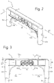
- the grip member 6 provided with a spring element 60 is shown in more detail in figures 2 and 3 , whereas the spring element 60 itself is shown in more detail in figure 4 .
- the spring element 60 is integrally formed with the grip member 6 by injection moulding of a suitable plastic, and is positioned at a center position of the grip member 6.
- the grip member 6 comprises a cross-element 61 having a longitudinal direction 62 extending about parallel to the frontal plane 3.
- two jackets (62a, 62b) for releasably receiving the proximal ends (7a, 7b) of the support poles (5a, 5b).
- the spring element 60 is positioned at a center position of the grip member 6, and in particular forms a central part of the cross-element 61.
- End parts (63a, 63b) of the cross-element 61 are relatively stiff compared to the spring element 60.
- parts (63a, 63b) are provided with stiffening ribs 63c as shown. This not only provides sufficient bending stiffness of parts (63a, 63b) about an axis 4 running perpendicular to a plane of the cross-element 61 and to the frontal plane 3 with the device in an upright position, but also provides sufficient torsional stiffness to the device 1.
- the releasable connection between the support poles (5a, 5b) and the jackets (62a, 62b) comprises a locking pin 11 that engages in aligned wall openings 80 of the jacket (62a, 62b) and wall openings 50 of a support pole (5a, 5b).
- the locking pin 11 is held in a locking position by means of a spring 110 and can be pushed in the direction 111 into an unlocking position in which the locking pin 11 leaves the wall opening 80 of the jacket (62a, 62b) clear. In this position, each pole (5a, 5b) may be slid out of the corresponding jacket (62a, 62b).
- the spring element 60 comprises a portion of the grip member 6 having a reduced height 64, relative to the (mean) height 65 of the grip member 6 and of the cross-element 61 in particular. Since the spring element 60 has an upper rim that is thicker than a lower rim, the spring element 60 is configured such that the initial spring force experienced when moving the distal ends (8a, 8b) towards one another (according to arrows (70a, 70b) is smaller than the initial spring force experienced when moving the distal ends (8a, 8b) away from one another according to the arrows (71a, 71b).
- the spring element 60 has a total height about equal to the height 65 of the cross-element 61 yet has an asymmetrical shape with respect to a line 66 extending at half height.
- the spring element 60 further comprises a number of deformable wall parts 67 extending substantially in a height direction 68 of the spring element 60.
- the deformable wall parts 67 are arranged parallel to each other in a length direction 62 of the grip member 6 and spring element 60.
- the deformable wall parts 67 comprise projections 69 that extend out of a plane of the deformable wall parts 67. Some wall parts 69a extend outward whereas other projections 69b extend inward. Yet other projections 69c extend from the end parts (63a, 63b) of the grip member 6.
- the projections 69 do not contact each other in an initial or rest position of the device 1, nor when the support poles (5a, 5b) are initially brought towards one another with a force corresponding to the initial spring force.
- Increasing the spring force in bringing the distal end (8a, 8b) of the support poles (5a, 5b) towards one another will deform the deformable wall parts 67 until projections 69 or at least some of them contact each other when moving the distal ends (8a, 8b) towards one another over a certain transverse distance.
- This distance is a design consideration and can be chosen by varying the distance between the projections 69 and/or varying the stiffness of the wall parts 67.
- the support poles (5a, 5b) do not substantially bend when moving the distal ends (8a, 8b) of the support poles (5a, 5b) under bias towards and away from one another in a transverse direction according to the arrows (11a, 11b, 12a, 12b).
- the distal outer ends (8a, 8b) By pushing the support poles (5a, 5b) slightly inwards, the distal outer ends (8a, 8b) are moved inward by deformation of the spring element 60 as according to the arrows (12a, 12b). Should the support poles (5a, 5b) be pulled slightly outwards, the distal outer ends (8a, 8b) then move outward in a direction opposite to that of arrows (12a, 12b), i.e. according to arrows (11a, 11b).
- first stocking expanding elements (15a, 15b) are directed toward the proximal outer end (7a, 7b), while the second stocking expanding elements (14a, 14b) are directed toward the distal outer end (8a, 8b). Because the first and second stocking expanding elements point in opposite directions, spoon elements (13a, 13b) take a substantially S-like form.
- the stocking expanding elements (14a, 14b, 15a, 15b) have a form which is substantially flat and to some extent curved, whereby a more or less concave surface fitting onto the shape of the lower leg is created on the inner side of stocking expanding elements (14a, 14b, 15a, 15b).
- Stocking expanding elements (14a, 14b, 15a, 15b) are rounded and made somewhat blunt at the corners so that a compression stocking can be tensioned there over without much risk of damage due to excessive local stretching. Because the first stocking expanding elements (15a, 15b) in the sagittal plane 2 form an angle of 120 degrees with the longitudinal axis of the associated support (5a, 5b) and the second stocking expanding elements (14a, 14b) in the sagittal plane 2 form an angle of 90 degrees with the longitudinal axis of the associated support (5a, 5b), and are held a distance of 6 to 7 centimetres from the support poles (5a, 5b), support poles (5a, 5b) or the grip member 6 are prevented from coming into contact with the shinbone during use of the assist device 1.
- assist device 1 can be manufactured from any material suitable for the purpose.
- Components such as the spoon elements (13a, 13b), grip member 6 and optionally sleeve handle 10 are thus preferably made by injection moulding of glass fibre-reinforced plastic.
- Other components such as the fixing pins 11 and spring 110 are preferably made of steel, while support poles (5a, 5b) are typically made of anodized aluminium.
- assist device 1 consists of pre-assembled components, it can be easily assembled or disassembled by a user.
- the division into components further ensures that assist device 1 can be packaged, shipped and stored in compact form. This moreover provides the option of length adjustment in accordance with build, height and reach, and adjustment of the opening range of a compression stocking arranged on the assist device.
- a compression stocking can be pulled on as follows using assist device 1. Assist device 1 is placed upside down with the grip member 6 resting on a ground surface between the legs of the user. The compression stocking is then clamped with the seam (or rear side) directed upward at the heel between the second stocking expanding elements (14a, 14b), which point upward in the upside down position. The upper edge of the compression stocking is then folded back over the other (first) stocking expanding elements (15a, 15b). This does not involve any appreciable tension.
- An elongated sliding strip of a flexible, smooth material, for instance spinnaker cloth, can then also be placed with a relatively short outer end in the compression stocking, wherein the remaining, relatively long part is likewise clamped between the second stocking expanding elements (14a, 14b) together with the heel part of the compression stocking.
- Assist device 1 is then turned over again and placed in a position in which the grip member 6 is allocated above the expanding elements (13a, 13b). The latter rest on the ground, at least the second expanding elements (14a, 14b).
- the support poles (5a, 5b) are then slightly brought outward. This movement places the compression stocking under tension and widens the opening for a foot of the user.
- the first stocking expanding elements (15a, 15b) over which the compression stocking is tensioned are set down on the ground close to the foot, in front of the toes, after which the foot is pushed into the opening of the compression stocking.
- the opening is sufficiently large due to the compression energy stored in the spring element 60.
- the compression stocking is pulled further upward.
- the upper body can hereby optionally also assist in pulling up the compression stocking along the leg by leaning backwards a little.
- the compression stocking is pulled further until it is in place.
- Stocking expanding elements (15a, 15b) are then removed from the compression stocking, and the optionally present sliding strip is pulled from between the leg and the stocking via the top side. If desired, the compression stocking can be pulled slightly further using manual force.
- the same assist device 1 can likewise be used for the purpose of pulling off a compression stocking.
- the distal (second) stocking expanding elements (14a, 14b) point downward here, and support poles (5a, 5b) rest along the body with the grip member 6 resting in the lap of a patient.
- the second stocking expanding elements (14a, 14b) are pushed into the compression stocking on either side of the lower leg via the top side of the compression stocking.
- the compression stocking is then pushed downward using the grip member 6 of support poles (5a, 5b).
- stocking expanding elements (14a, 14b) are removed from the compression stocking. If desired, use can also be made of a sliding strip when the stocking is being pulled off.
- a (therapeutic) compression stocking can be pulled on and off as described in simple manner using little force and small movements.
- the assist device is easy to handle, light in weight and, owing to the modular structure, saves storage space.
- Arranging a compression stocking over the stocking expanding elements is also simple. Because the spoon elements take an ergonomic form and are covered with relatively smooth rubber, these elements cause less friction and do not press painfully into the skin of a user.
- the assist device may further be adjustable in length, which increases the convenience of use and the flexibility thereof.
Landscapes
- Orthopedics, Nursing, And Contraception (AREA)
Claims (14)
- Hilfsvorrichtung (1) zum Ziehen eines Kompressionsstrumpfs auf und von einem Bein, die ein Paar langgestreckte Haltestangen (5a, 5b), die in einer Längsrichtung, jede mit einem proximalen Ende (7a, 7b) und einem distalen Ende (8a, 8b), verlaufen, aufweist, wobei die Haltestangen (5a, 5b) an ihrem proximalen Ende (7a, 7b) durch ein Greifelement (6) verbunden sind, und an ihrem distalen Ende (8a, 8b) jeweils ein Strumpfdehnelement (14a, 14b, 15a, 15b) aufweisen, das ein benachbart angeordnetes Paar bildet, über dem ein Kompressionsstrumpf angeordnet werden kann, wobei das Greifelement (6) ein Querelement (61) mit einer Länge in einer Längsrichtung (62) und einer Höhe (65) in der Längsrichtung der Haltestangen (5a, 5b) und ein Federelement (60) aufweist, das konfiguriert ist, um die distalen Enden (8a, 8b) der Haltestangen (5a, 5b) unter einer Vorspannung in einer Richtung (9) quer zu der Längsrichtung der Haltestangen (5a, 5b) aufeinander zu und voneinander weg zu bewegen, wobei das Federelement (60) in einem Abschnitt des Querelements (61) mit einer verringerten Höhe (64) enthalten ist, eine Länge in der Längsrichtung (62) des Querelements (61) und eine Höhe in der Längsrichtung der Haltestangen (5a, 5b) hat und eine asymmetrische Form in Bezug auf eine Linie (66) hat, die sich auf halber Höhe in der Längsrichtung (62) des Querelements (61) erstreckt.
- Hilfsvorrichtung nach Anspruch 1, wobei das Federelement (60) derart konfiguriert ist, dass die anfängliche Federkraft, die auftritt, wenn die distalen Enden (8a, 8b) aufeinander zu bewegt werden, sich von der anfänglichen Federkraft, die auftritt, wenn die distalen Enden (8a, 8b) voneinander weg bewegt werden, unterscheidet und bevorzugt kleiner als die anfängliche Kraft ist, die auftritt, wenn die distalen Enden (8a, 8b) voneinander weg bewegt werden.
- Hilfsvorrichtung nach Anspruch 1 oder 2, wobei das Federelement (60) derart konfiguriert ist, dass die Federkraft, die auftritt, wenn die distalen Enden (8a, 8b) aufeinander zu bewegt werden, von der anfänglichen Federkraft zu einer Endfederkraft, die größer als die anfängliche Federkraft ist, zunimmt.
- Hilfsvorrichtung nach einem der vorhergehenden Ansprüche, wobei die Haltestangen (5a, 5b) sich nicht wesentlich biegen, wenn die distalen Enden (8a, 8b) der Haltestangen (5a, 5b) unter der Vorspannung in der Querrichtung (9) aufeinander zu und voneinander weg bewegt werden.
- Hilfsvorrichtung nach einem der vorhergehenden Ansprüche, wobei das Federelement integral mit dem Greifelement (6) ausgebildet ist.
- Hilfsvorrichtung nach einem der vorhergehenden Ansprüche, wobei das Federelement (60) eine Anzahl verformbarer Wandteile (67) aufweist, die sich im Wesentlichen in einer Höhenrichtung des Federelements erstrecken und in der Längenrichtung (62) des Federelements (60) parallel zueinander angeordnet sind.
- Hilfsvorrichtung nach Anspruch 6, wobei die verformbaren Wandteile (67) Vorsprünge (69, 69a, 69b, 69c) aufweisen, wobei die Vorsprünge einander in einer Anfangsposition, die der anfänglichen Federkraft entspricht, nicht berühren.
- Hilfsvorrichtung nach Anspruch 7, wobei die Vorsprünge (69, 69a, 69b, 69c) einander berühren, wenn die distalen Enden (8a, 8b) über eine gewisse Querstrecke aufeinander zu bewegt werden.
- Hilfsvorrichtung nach einem der vorhergehenden Ansprüche, wobei verformbare Wandteile (67) des Federelements (60) durch gekrümmte Wandteile, die an einer Unterseite des Federelements angeordnet sind, wechselseitig verbunden sind.
- Hilfsvorrichtung nach einem der vorhergehenden Ansprüche, wobei das Federelement (60) mit einer flexiblen Hülse (10) bedeckt ist.
- Hilfsvorrichtung nach einem der vorhergehenden Ansprüche, wobei das Greifelement (6) Mäntel (62a, 62b) zum lösbaren Aufnehmen der proximalen Enden der Haltestangen aufweist.
- Hilfsvorrichtung nach Anspruch 11, wobei die lösbare Verbindung zwischen den Haltestangen (5a, 5b) und den Hülsen einen Arretierstift (11) aufweist, der in ausgerichtete Wandöffnungen (80) des Mantels (62a, 62b) und einer Haltestange (5a, 5b) eingreift, mittels einer Feder (110) in einer Arretierungsposition gehalten wird und in eine Entriegelungsposition gedrückt werden kann, in welcher der Arretierstift (11) die Wandöffnung (80) des Mantels (62a, 62b) frei lässt.
- Verfahren zum Ziehen eines Kompressionsstrumpfs auf ein Bein, das aufweist:a) Bereitstellen einer Hilfsvorrichtung nach einem der vorhergehenden Ansprüche;b) Aufeinander-zu-Bewegen der distalen Enden der Haltestangen unter einer Vorspannung in einer Querrichtung und Aufbringen eines Kompressionsstrumpfs über Strumpfdehnelementen, wodurch eine Öffnung für einen Fuß ausgebildet wird;c) Einsetzen des Fußes in die Öffnung;d) Bewegen der Hilfsvorrichtung in die proximale Richtung, wobei der Kompressionsstrumpf zusammen mit den Strumpfdehnelementen entlang des Unterschenkels in Richtung des Knies und in die gewünschte Position bewegt wird; unde) Entfernen der Strumpfdehnelemente von dem Kompressionsstrumpf.
- Verfahren zum Ziehen eines Kompressionsstrumpfs von einem Bein, das aufweist:a) Bereitstellen einer Hilfsvorrichtung nach einem der Ansprüche 1-12;b) Befestigen der Strumpfdehnelemente an einem Kompressionsstrumpf, der um das Bein herum angeordnet ist, indem die Strumpfdehnelemente unter einem oberen Rand des Kompressionsstrumpfs positioniert werden;c) Bewegen der Hilfsvorrichtung in die distale Richtung, wobei der Kompressionsstrumpf zusammen mit den Stumpfdehnelementen entlang des Unterschenkels in Richtung des Fußes bewegt wird;d) Abziehen des Kompressionsstrumpfs über den Fuß, bis er von dem Fuß befreit ist; unde) Entfernen der Strumpfdehnelemente von dem Kompressionsstrumpf.
Applications Claiming Priority (1)
| Application Number | Priority Date | Filing Date | Title |
|---|---|---|---|
| NL2020515A NL2020515B1 (en) | 2018-03-01 | 2018-03-01 | Assist device for pulling compression stockings on and off |
Publications (2)
| Publication Number | Publication Date |
|---|---|
| EP3533362A1 EP3533362A1 (de) | 2019-09-04 |
| EP3533362B1 true EP3533362B1 (de) | 2020-11-18 |
Family
ID=62685031
Family Applications (1)
| Application Number | Title | Priority Date | Filing Date |
|---|---|---|---|
| EP19160016.2A Active EP3533362B1 (de) | 2018-03-01 | 2019-02-28 | Hilfsvorrichtung zum an- und ausziehen von kompressionssocken |
Country Status (3)
| Country | Link |
|---|---|
| EP (1) | EP3533362B1 (de) |
| DK (1) | DK3533362T3 (de) |
| NL (1) | NL2020515B1 (de) |
Family Cites Families (4)
| Publication number | Priority date | Publication date | Assignee | Title |
|---|---|---|---|---|
| US4066194A (en) * | 1977-04-29 | 1978-01-03 | Leland Ragnvald G | Sock donning assist device |
| US4638932A (en) * | 1984-12-04 | 1987-01-27 | Keller Henry C | Combination tool to pull up and remove socks, shorts and trousers |
| JP2000270996A (ja) * | 1999-03-26 | 2000-10-03 | Satoshi Takagi | 障害者用靴下着脱器具 |
| JP3089824U (ja) * | 2002-04-16 | 2002-11-15 | 株式会社ハイワース | 高齢者・腰痛者・肥満者用靴下着用具 |
-
2018
- 2018-03-01 NL NL2020515A patent/NL2020515B1/en active
-
2019
- 2019-02-28 DK DK19160016.2T patent/DK3533362T3/da active
- 2019-02-28 EP EP19160016.2A patent/EP3533362B1/de active Active
Non-Patent Citations (1)
| Title |
|---|
| None * |
Also Published As
| Publication number | Publication date |
|---|---|
| EP3533362A1 (de) | 2019-09-04 |
| NL2020515B1 (en) | 2019-09-12 |
| DK3533362T3 (da) | 2021-01-11 |
Similar Documents
| Publication | Publication Date | Title |
|---|---|---|
| CN110662520B (zh) | 柔性腿部支撑膜、腿部支撑框架及移动式患者站立和起身辅助器 | |
| US9386875B2 (en) | Combination shoe horn and sock donning and doffing apparatus | |
| EP2043573B1 (de) | Kompressionsstrumpf-applikator | |
| JP5050211B2 (ja) | 生体力学的に得られる松葉杖 | |
| US11426323B2 (en) | Multi-functional foot crutch | |
| US9498077B2 (en) | Footwear application assisting apparatus | |
| EP3515263B1 (de) | Vorrichtung zum anziehen von socken | |
| US7364056B2 (en) | Apparatus for wearing socks | |
| US20050115994A1 (en) | Device for putting on and taking off a support stocking | |
| EP3533362B1 (de) | Hilfsvorrichtung zum an- und ausziehen von kompressionssocken | |
| US8047216B2 (en) | Standing aid | |
| US20070145086A1 (en) | Self-help devie for handling socks, supporet stockings and stockings in general | |
| JP2014509898A (ja) | ベッドに横になった姿勢から座った姿勢に及びその逆の姿勢変化も同様に行うような介助器具を用いて障害者を移動するための方法及びこの方法のための介助器具 | |
| EP2895035B1 (de) | Hilfe zum an- und ausziehen elastischer strümpfe | |
| KR20250059877A (ko) | 양말 착탈 보조장치 | |
| KR102887190B1 (ko) | 양말 착용을 위한 원터치 보조장치 | |
| US12414872B2 (en) | Device for supporting a lower limb | |
| CN113288733A (zh) | 高位截瘫病人助行器 | |
| JP2025132615A (ja) | 靴ベラ | |
| KR101956301B1 (ko) | 콘택트렌즈의 착용을 돕는 렌즈착용기구 | |
| HK40014255A (en) | Flexible leg supporting membrane, leg support frame and mobile patient standing and raising aid | |
| HK40014255B (en) | Flexible leg supporting membrane, leg support frame and mobile patient standing and raising aid | |
| TWM414839U (en) | Socks wearing assisting device |
Legal Events
| Date | Code | Title | Description |
|---|---|---|---|
| PUAI | Public reference made under article 153(3) epc to a published international application that has entered the european phase |
Free format text: ORIGINAL CODE: 0009012 |
|
| STAA | Information on the status of an ep patent application or granted ep patent |
Free format text: STATUS: THE APPLICATION HAS BEEN PUBLISHED |
|
| AK | Designated contracting states |
Kind code of ref document: A1 Designated state(s): AL AT BE BG CH CY CZ DE DK EE ES FI FR GB GR HR HU IE IS IT LI LT LU LV MC MK MT NL NO PL PT RO RS SE SI SK SM TR |
|
| AX | Request for extension of the european patent |
Extension state: BA ME |
|
| STAA | Information on the status of an ep patent application or granted ep patent |
Free format text: STATUS: REQUEST FOR EXAMINATION WAS MADE |
|
| 17P | Request for examination filed |
Effective date: 20200304 |
|
| RBV | Designated contracting states (corrected) |
Designated state(s): AL AT BE BG CH CY CZ DE DK EE ES FI FR GB GR HR HU IE IS IT LI LT LU LV MC MK MT NL NO PL PT RO RS SE SI SK SM TR |
|
| GRAP | Despatch of communication of intention to grant a patent |
Free format text: ORIGINAL CODE: EPIDOSNIGR1 |
|
| STAA | Information on the status of an ep patent application or granted ep patent |
Free format text: STATUS: GRANT OF PATENT IS INTENDED |
|
| INTG | Intention to grant announced |
Effective date: 20200609 |
|
| GRAS | Grant fee paid |
Free format text: ORIGINAL CODE: EPIDOSNIGR3 |
|
| GRAA | (expected) grant |
Free format text: ORIGINAL CODE: 0009210 |
|
| STAA | Information on the status of an ep patent application or granted ep patent |
Free format text: STATUS: THE PATENT HAS BEEN GRANTED |
|
| AK | Designated contracting states |
Kind code of ref document: B1 Designated state(s): AL AT BE BG CH CY CZ DE DK EE ES FI FR GB GR HR HU IE IS IT LI LT LU LV MC MK MT NL NO PL PT RO RS SE SI SK SM TR |
|
| REG | Reference to a national code |
Ref country code: GB Ref legal event code: FG4D |
|
| REG | Reference to a national code |
Ref country code: CH Ref legal event code: EP |
|
| REG | Reference to a national code |
Ref country code: IE Ref legal event code: FG4D |
|
| REG | Reference to a national code |
Ref country code: DE Ref legal event code: R096 Ref document number: 602019001324 Country of ref document: DE |
|
| REG | Reference to a national code |
Ref country code: CH Ref legal event code: NV Representative=s name: NOVAGRAAF INTERNATIONAL SA, CH Ref country code: AT Ref legal event code: REF Ref document number: 1334806 Country of ref document: AT Kind code of ref document: T Effective date: 20201215 |
|
| REG | Reference to a national code |
Ref country code: DK Ref legal event code: T3 Effective date: 20210104 |
|
| REG | Reference to a national code |
Ref country code: SE Ref legal event code: TRGR |
|
| REG | Reference to a national code |
Ref country code: NL Ref legal event code: FP |
|
| REG | Reference to a national code |
Ref country code: AT Ref legal event code: MK05 Ref document number: 1334806 Country of ref document: AT Kind code of ref document: T Effective date: 20201118 |
|
| PG25 | Lapsed in a contracting state [announced via postgrant information from national office to epo] |
Ref country code: GR Free format text: LAPSE BECAUSE OF FAILURE TO SUBMIT A TRANSLATION OF THE DESCRIPTION OR TO PAY THE FEE WITHIN THE PRESCRIBED TIME-LIMIT Effective date: 20210219 Ref country code: NO Free format text: LAPSE BECAUSE OF FAILURE TO SUBMIT A TRANSLATION OF THE DESCRIPTION OR TO PAY THE FEE WITHIN THE PRESCRIBED TIME-LIMIT Effective date: 20210218 Ref country code: FI Free format text: LAPSE BECAUSE OF FAILURE TO SUBMIT A TRANSLATION OF THE DESCRIPTION OR TO PAY THE FEE WITHIN THE PRESCRIBED TIME-LIMIT Effective date: 20201118 Ref country code: PT Free format text: LAPSE BECAUSE OF FAILURE TO SUBMIT A TRANSLATION OF THE DESCRIPTION OR TO PAY THE FEE WITHIN THE PRESCRIBED TIME-LIMIT Effective date: 20210318 Ref country code: RS Free format text: LAPSE BECAUSE OF FAILURE TO SUBMIT A TRANSLATION OF THE DESCRIPTION OR TO PAY THE FEE WITHIN THE PRESCRIBED TIME-LIMIT Effective date: 20201118 |
|
| PG25 | Lapsed in a contracting state [announced via postgrant information from national office to epo] |
Ref country code: AT Free format text: LAPSE BECAUSE OF FAILURE TO SUBMIT A TRANSLATION OF THE DESCRIPTION OR TO PAY THE FEE WITHIN THE PRESCRIBED TIME-LIMIT Effective date: 20201118 Ref country code: LV Free format text: LAPSE BECAUSE OF FAILURE TO SUBMIT A TRANSLATION OF THE DESCRIPTION OR TO PAY THE FEE WITHIN THE PRESCRIBED TIME-LIMIT Effective date: 20201118 Ref country code: IS Free format text: LAPSE BECAUSE OF FAILURE TO SUBMIT A TRANSLATION OF THE DESCRIPTION OR TO PAY THE FEE WITHIN THE PRESCRIBED TIME-LIMIT Effective date: 20210318 Ref country code: PL Free format text: LAPSE BECAUSE OF FAILURE TO SUBMIT A TRANSLATION OF THE DESCRIPTION OR TO PAY THE FEE WITHIN THE PRESCRIBED TIME-LIMIT Effective date: 20201118 Ref country code: BG Free format text: LAPSE BECAUSE OF FAILURE TO SUBMIT A TRANSLATION OF THE DESCRIPTION OR TO PAY THE FEE WITHIN THE PRESCRIBED TIME-LIMIT Effective date: 20210218 |
|
| REG | Reference to a national code |
Ref country code: LT Ref legal event code: MG9D |
|
| PG25 | Lapsed in a contracting state [announced via postgrant information from national office to epo] |
Ref country code: HR Free format text: LAPSE BECAUSE OF FAILURE TO SUBMIT A TRANSLATION OF THE DESCRIPTION OR TO PAY THE FEE WITHIN THE PRESCRIBED TIME-LIMIT Effective date: 20201118 |
|
| PG25 | Lapsed in a contracting state [announced via postgrant information from national office to epo] |
Ref country code: CZ Free format text: LAPSE BECAUSE OF FAILURE TO SUBMIT A TRANSLATION OF THE DESCRIPTION OR TO PAY THE FEE WITHIN THE PRESCRIBED TIME-LIMIT Effective date: 20201118 Ref country code: EE Free format text: LAPSE BECAUSE OF FAILURE TO SUBMIT A TRANSLATION OF THE DESCRIPTION OR TO PAY THE FEE WITHIN THE PRESCRIBED TIME-LIMIT Effective date: 20201118 Ref country code: SK Free format text: LAPSE BECAUSE OF FAILURE TO SUBMIT A TRANSLATION OF THE DESCRIPTION OR TO PAY THE FEE WITHIN THE PRESCRIBED TIME-LIMIT Effective date: 20201118 Ref country code: SM Free format text: LAPSE BECAUSE OF FAILURE TO SUBMIT A TRANSLATION OF THE DESCRIPTION OR TO PAY THE FEE WITHIN THE PRESCRIBED TIME-LIMIT Effective date: 20201118 Ref country code: RO Free format text: LAPSE BECAUSE OF FAILURE TO SUBMIT A TRANSLATION OF THE DESCRIPTION OR TO PAY THE FEE WITHIN THE PRESCRIBED TIME-LIMIT Effective date: 20201118 Ref country code: LT Free format text: LAPSE BECAUSE OF FAILURE TO SUBMIT A TRANSLATION OF THE DESCRIPTION OR TO PAY THE FEE WITHIN THE PRESCRIBED TIME-LIMIT Effective date: 20201118 |
|
| REG | Reference to a national code |
Ref country code: DE Ref legal event code: R097 Ref document number: 602019001324 Country of ref document: DE |
|
| PLBE | No opposition filed within time limit |
Free format text: ORIGINAL CODE: 0009261 |
|
| STAA | Information on the status of an ep patent application or granted ep patent |
Free format text: STATUS: NO OPPOSITION FILED WITHIN TIME LIMIT |
|
| PG25 | Lapsed in a contracting state [announced via postgrant information from national office to epo] |
Ref country code: MC Free format text: LAPSE BECAUSE OF FAILURE TO SUBMIT A TRANSLATION OF THE DESCRIPTION OR TO PAY THE FEE WITHIN THE PRESCRIBED TIME-LIMIT Effective date: 20201118 |
|
| 26N | No opposition filed |
Effective date: 20210819 |
|
| PG25 | Lapsed in a contracting state [announced via postgrant information from national office to epo] |
Ref country code: AL Free format text: LAPSE BECAUSE OF FAILURE TO SUBMIT A TRANSLATION OF THE DESCRIPTION OR TO PAY THE FEE WITHIN THE PRESCRIBED TIME-LIMIT Effective date: 20201118 Ref country code: IT Free format text: LAPSE BECAUSE OF FAILURE TO SUBMIT A TRANSLATION OF THE DESCRIPTION OR TO PAY THE FEE WITHIN THE PRESCRIBED TIME-LIMIT Effective date: 20201118 Ref country code: LU Free format text: LAPSE BECAUSE OF NON-PAYMENT OF DUE FEES Effective date: 20210228 |
|
| PG25 | Lapsed in a contracting state [announced via postgrant information from national office to epo] |
Ref country code: SI Free format text: LAPSE BECAUSE OF FAILURE TO SUBMIT A TRANSLATION OF THE DESCRIPTION OR TO PAY THE FEE WITHIN THE PRESCRIBED TIME-LIMIT Effective date: 20201118 |
|
| PG25 | Lapsed in a contracting state [announced via postgrant information from national office to epo] |
Ref country code: ES Free format text: LAPSE BECAUSE OF FAILURE TO SUBMIT A TRANSLATION OF THE DESCRIPTION OR TO PAY THE FEE WITHIN THE PRESCRIBED TIME-LIMIT Effective date: 20201118 Ref country code: IE Free format text: LAPSE BECAUSE OF NON-PAYMENT OF DUE FEES Effective date: 20210228 |
|
| PG25 | Lapsed in a contracting state [announced via postgrant information from national office to epo] |
Ref country code: IS Free format text: LAPSE BECAUSE OF FAILURE TO SUBMIT A TRANSLATION OF THE DESCRIPTION OR TO PAY THE FEE WITHIN THE PRESCRIBED TIME-LIMIT Effective date: 20210318 |
|
| P01 | Opt-out of the competence of the unified patent court (upc) registered |
Effective date: 20230518 |
|
| PG25 | Lapsed in a contracting state [announced via postgrant information from national office to epo] |
Ref country code: CY Free format text: LAPSE BECAUSE OF FAILURE TO SUBMIT A TRANSLATION OF THE DESCRIPTION OR TO PAY THE FEE WITHIN THE PRESCRIBED TIME-LIMIT Effective date: 20201118 |
|
| PG25 | Lapsed in a contracting state [announced via postgrant information from national office to epo] |
Ref country code: HU Free format text: LAPSE BECAUSE OF FAILURE TO SUBMIT A TRANSLATION OF THE DESCRIPTION OR TO PAY THE FEE WITHIN THE PRESCRIBED TIME-LIMIT; INVALID AB INITIO Effective date: 20190228 |
|
| PG25 | Lapsed in a contracting state [announced via postgrant information from national office to epo] |
Ref country code: MK Free format text: LAPSE BECAUSE OF FAILURE TO SUBMIT A TRANSLATION OF THE DESCRIPTION OR TO PAY THE FEE WITHIN THE PRESCRIBED TIME-LIMIT Effective date: 20201118 |
|
| PG25 | Lapsed in a contracting state [announced via postgrant information from national office to epo] |
Ref country code: TR Free format text: LAPSE BECAUSE OF FAILURE TO SUBMIT A TRANSLATION OF THE DESCRIPTION OR TO PAY THE FEE WITHIN THE PRESCRIBED TIME-LIMIT Effective date: 20201118 |
|
| PG25 | Lapsed in a contracting state [announced via postgrant information from national office to epo] |
Ref country code: MT Free format text: LAPSE BECAUSE OF FAILURE TO SUBMIT A TRANSLATION OF THE DESCRIPTION OR TO PAY THE FEE WITHIN THE PRESCRIBED TIME-LIMIT Effective date: 20201118 |
|
| PGFP | Annual fee paid to national office [announced via postgrant information from national office to epo] |
Ref country code: NL Payment date: 20250227 Year of fee payment: 7 |
|
| PGFP | Annual fee paid to national office [announced via postgrant information from national office to epo] |
Ref country code: DE Payment date: 20250227 Year of fee payment: 7 |
|
| PGFP | Annual fee paid to national office [announced via postgrant information from national office to epo] |
Ref country code: DK Payment date: 20250225 Year of fee payment: 7 |
|
| PGFP | Annual fee paid to national office [announced via postgrant information from national office to epo] |
Ref country code: SE Payment date: 20250227 Year of fee payment: 7 |
|
| PGFP | Annual fee paid to national office [announced via postgrant information from national office to epo] |
Ref country code: BE Payment date: 20250227 Year of fee payment: 7 Ref country code: CH Payment date: 20250306 Year of fee payment: 7 |
|
| PGFP | Annual fee paid to national office [announced via postgrant information from national office to epo] |
Ref country code: FR Payment date: 20250225 Year of fee payment: 7 |
|
| PGFP | Annual fee paid to national office [announced via postgrant information from national office to epo] |
Ref country code: GB Payment date: 20250227 Year of fee payment: 7 |