EP2895035B1 - Hilfe zum an- und ausziehen elastischer strümpfe - Google Patents
Hilfe zum an- und ausziehen elastischer strümpfe Download PDFInfo
- Publication number
- EP2895035B1 EP2895035B1 EP13767151.7A EP13767151A EP2895035B1 EP 2895035 B1 EP2895035 B1 EP 2895035B1 EP 13767151 A EP13767151 A EP 13767151A EP 2895035 B1 EP2895035 B1 EP 2895035B1
- Authority
- EP
- European Patent Office
- Prior art keywords
- aid
- tensioning
- supports
- elastic stocking
- stocking
- Prior art date
- Legal status (The legal status is an assumption and is not a legal conclusion. Google has not performed a legal analysis and makes no representation as to the accuracy of the status listed.)
- Active
Links
Images


Classifications
-
- A—HUMAN NECESSITIES
- A47—FURNITURE; DOMESTIC ARTICLES OR APPLIANCES; COFFEE MILLS; SPICE MILLS; SUCTION CLEANERS IN GENERAL
- A47G—HOUSEHOLD OR TABLE EQUIPMENT
- A47G25/00—Household implements used in connection with wearing apparel; Dress, hat or umbrella holders
- A47G25/90—Devices for domestic use for assisting in putting-on or pulling-off clothing, e.g. stockings or trousers
- A47G25/905—Devices for domestic use for assisting in putting-on or pulling-off clothing, e.g. stockings or trousers for stockings
- A47G25/908—Removal devices
Definitions
- the invention relates to an aid for pulling on and off elastic stockings, in particular therapeutic elastic stockings.
- the invention likewise relates to a method for pulling elastic stockings on and off while making use of the device.
- a therapeutic elastic stocking is frequently applied as medical aid for users with varicose veins and other vascular problems.
- the elastic stocking must exert pressure on the leg with a determined tensioning force. Owing to the desired tensioning force the user encounters problems when pulling on and pulling off the elastic stocking, this requiring sufficient strength and mobility of the user. It is however precisely in this respect that the user group is often limited, for instance due to advanced age, illness or disorders of the support and locomotion system.
- the invention has for its object to provide an aid for pulling on and off elastic stockings, in particular therapeutic elastic stockings, more easily. According to the invention this object is achieved by an aid as according to claim 1.
- the aid comprises two mutually coupled elongate supports, each with a proximal gripping end and a distal tensioning end, wherein the coupling comprises a pivoting connection which is placed between the two outer ends and with which the supports can be moved in the manner of scissors in a frontal plane, and wherein the supports each comprise a first tensioning element between the tensioning end and the pivoting connection, which elements form an adjacently placed pair over which a stocking can be arranged.
- the pivoting connection is placed a transverse distance from the supports by means of spacers which preferably run in a frontal plane, and the spacers comprise or form a handle.
- the aid is particularly suitable for users with reduced mobility, possibly in combination with decreased strength. Only a limited degree of mobility is expected of the user, for instance in that he/she is able to reach his/her ankle when bending at the hip and knee.
- the coupling between the two supports has a compound function, wherein the coupling not only serves for pivotal coupling of the supports but also functions as a handle for grasping of the aid.
- the aid has the feature that the spacers together define a distance between the supports which amounts to at least a hand's width.
- at least part of the spacers form the handle with which the aid can be gripped with at least one hand.
- the handle preferably extends in a frontal plane.
- the aid according to the invention is suitable for pulling an elastic stocking on and off to the knee, wherein the elastic stocking can have an open as well as a closed toe piece.
- proximal, distal, frontal and sagittal are defined in relation to a user who is standing upright (or sitting upright during use) and holding the aid in upright position at the gripping ends of the supports of the aid.
- This position of the aid is referred to in the context of this application as the tensioning position of the aid.
- the tensioning position In the tensioning position the tensioning end of the supports is located on a substrate such as the ground. It may be necessary to turn the aid upside down during use.
- the definitions remain the same in such an upside down position, in other words the proximal gripping ends will be (temporarily) located distally relative to the user.
- the elastic stocking can be opened out and tensioned with little force by moving the gripping ends in the opposite direction.
- the aid has the feature that the pivoting connection is placed at a distance from the supports in a frontal plane by means of spacers. Although the distance from the pivoting connection to the tensioning end can be chosen within broad limits, an aid with a pivoting connection situated at a distance of 20 to 35 cm from the tensioning end provides an optimal convenience of use, wherein the forces and movements required to pull the stocking on and off are small.
- an optimal balance between the force to be exerted and the degree of widening (opening out) of the elastic stocking is achieved in an embodiment of the aid wherein the distance from the pivoting connection to the tensioning end amounts to between 1/8 and 3/5 of the total length of the supports, and more preferably to between 1/5 and 1 ⁇ 2 of the total length of the supports.
- An embodiment according to the invention relates to an aid, wherein the spacers extend substantially perpendicularly of the supports and their combined length more preferably amounts to at least 10 cm.
- the pivoting handle is located at a favourable distance from the tensioning end.
- the second tensioning elements can be placed with one hand under an upper edge of an elastic stocking arranged around the leg, wherein the aid is held fast by the pivoting handle with the other hand.
- Another embodiment of the invention provides an aid, the supports of which each comprise a second tensioning element at the tensioning end, which elements form an adjacently placed pair over which a stocking can be arranged.
- An embodiment of an aid wherein the tensioning elements are placed at a distance from the supports in a sagittal plane of the aid by means of spacers has the advantage that neither the supports nor the pivoting connection are at risk of coming into contact with the shinbone during use of the aid.
- Another embodiment relates to an aid wherein in the tensioning position of the aid the spacers of the first tensioning elements run in the proximal direction and the spacers of the second tensioning elements in the distal direction.
- the first tensioning elements are more proximally situated than the second tensioning elements, this facilitating the use as both pull-off aid and pull-on aid.
- a further embodiment according to the invention relates to an aid wherein the first tensioning elements are directed toward the proximal outer end and the second tensioning elements toward the distal tensioning end, thus forming S-shaped spoon elements.
- the tensioning elements of the aid can in principle take any form. It is thus possible for instance that they are embodied in the form of ball-like elements, for instance made of rubber, arranged on a spacer.
- a practical embodiment provides an aid with supports which each comprise at the distal outer end a spoon element, the outer ends (or spoons) of which form the tensioning elements and the middle part of which forms the spacer.
- the spoons preferably take a flat and to some extent curved form here, thereby creating a slightly concave inner surface which fits onto the shape of the lower leg.
- the contours of the spoons are preferably round and blunt so that an elastic stocking can be tensioned thereover without appreciable risk of damage, for instance due to excessive local stretching.
- the aid has the feature that the supports comprise telescopically extendable parts which can be fixed by means of a locking member.
- the dimensions of the aid can hereby be adapted to (the abilities of) the user.
- the locking member is preferably situated in the spacers of the pivoting connection, wherein two functions (scissor movement and telescopic adjustment) are integrated into one component.
- the support parts to comprise openings in their peripheral surface and for the locking member to comprise a locking pin which is held by means of a spring in a locked position in which the locking pin engages in an opening of a support part, and which can be carried by means of a catch into an unlocked position in which the locking pin leaves the relevant opening clear.
- Such an embodiment keeps the support parts locked under the influence of the spring force, and unlocking requires a conscious action on the part of the user - unlocking by operating the catch. This enhances the safety of the aid.
- the supports each comprise a handle, preferably extending in a sagittal plane, on the gripping ends.
- An embodiment which is further improved in this respect makes use of supports which each comprise an auxiliary handle, preferably also extending in a sagittal plane, between the pivoting connection and the gripping ends.
- the two auxiliary handles provide the user with an additional gripping option, wherein the supports can be gripped at a different distances from the gripping end.
- the invention likewise relates to a method for pulling an elastic stocking on.
- the method comprises of
- Folding of the elastic stocking from the upper edge thereof back over the first tensioning elements preferably takes place over a distance covering between 1 ⁇ 4 and 1 ⁇ 2 of the total length of the elastic stocking, preferably to about 1/3 of the total length of the elastic stocking.
- the aid is placed upside down at the tensioning position in step b) with the gripping ends on the ground surface, the tensioning ends are moved toward each other and the elastic stocking is clamped between the second tensioning means, preferably at the position of the heel.
- the stocking is hereby fixed, whereby coupling of the first tensioning elements and the elastic stocking is considerably simplified.
- Another embodiment comprises a method wherein in step d) the aid is gripped in the tensioning position by the auxiliary handles and the proximal part of the supports rests on the front part of the shoulders.
- the upper body can if desired assist in pulling the elastic stocking up along the leg by leaning backwards.
- a flexible body made of a smooth material with low frictional resistance is introduced into the opening prior to insertion of the foot.
- a flexible body is for instance known from NL 8902619 and preferably comprises a flexible tube-like peripheral body of a smooth material with an insertion end for a foot, the peripheral body being provided with a lining of a smooth material.
- the lining is attached to the peripheral body at the position of the insertion end and can otherwise be moved freely relative to the peripheral body from an inward folded position, in which the lining is situated in the peripheral body, to an outward folded position in which the lining is situated outside the peripheral body.
- Such a flexible and smooth body makes the sliding of an elastic stocking along a surface considerably easier in that the body arranged between stocking and surface perceptibly reduces the friction forces. It is noted that the flexible body need in no way be tube-like. A single strip of flexible smooth material can also suffice, for instance a strip which is slightly longer than the elastic stocking and has a width of about 15 cm.
- the invention likewise relates to a method for pulling an elastic stocking off, comprising of
- step d) The widening of the peripheral opening in step d) can take place at any moment, such as prior to step c).
- the widening is however preferably carried out when the elastic stocking is situated at the position of the ankle.
- the aid according to the invention need not be adjusted at all for the purpose of pulling off elastic stockings as according to the above stated method.
- the dual functionality of the aid among other reasons because of the presence of the co-acting first and second tensioning means, provides a great advantage for the user.
- Figure 1 shows an aid 1 for pulling on and off an elastic stocking in ready-to-use position. Aid 1 is shown in upright position. For the relative positioning of the aid components reference is made in the context of this description to a sagittal plane 2 and a frontal plane 3 running at a right angle thereto in accordance with the planes defined in a user. Aid 1 comprises two elongate supports (5a, 5b) running in a longitudinal direction 4 and having a length of about 80 cm.
- the supports (5a, 5b) preferably have a low specific weight and are for instance made of aluminium, which is optionally anodized in the desired colour. The anodizing helps to prevent the aluminium giving off black residue onto body and clothing.
- the supports (5a, 5b) are mutually coupled by an intermediate pivoting connection 6.
- Each support (5a, 5b) has a proximal gripping end (7a, 7b) and a distal support end (8a, 8b).
- pivoting connection 6 is situated a distance of about 27 cm from the distal outer ends (8a, 8b).
- Pivoting connection 6 comprises spacers in the form of transverse profiles (9a, 9b) connected substantially rigidly at an outer end to the associated support (5a, 5b).
- the transverse profiles (9a, 9b) are mutually connected at their other outer end by means of a hinge, which is not visible because it is concealed from view by a rubber sleeve 10 arranged over the hinge.
- the rubber sleeve 10 forms a handle for the user.
- the hinge of pivoting connection 6 is held at a transverse distance from supports (5a, 5b) by the two transverse profiles (9a, 9b).
- the hinge is preferably a flat hinge only able to rotate around the rotation axis 4 lying perpendicularly of frontal plane 3.
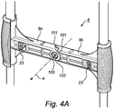
- Figure 4A shows schematically an embodiment of pivoting connection 6 according to the invention, wherein rubber sleeve 10 is omitted.
- Pivoting connection 6 comprises transverse profiles (9a, 9b) rotatable around rotation axis 4.
- the hinge comprises a metal bearing bush 100 received in a cylindrical recess 101 of pivoting outer ends of profiles (9a, 9b).
- Bearing bush 100 imparts stability to the hinge construction and prevents wearing away of recesses 101 in the transverse profiles (9a and 9b).
- Bearing bush 100 is enclosed in recesses 101 by means of a bolt connection, this comprising in the shown embodiment a low socket-head bolt 102 with inner hexagon 103, and a low locking nut 104. Because the end surfaces of bearing bush 100 are in contact in the desired tightened state with the clamping surfaces of socket-head bolt 102 and locking nut 104, bearing bush 100 prevents excessive tightening of the bolt connection.
- Locking nut 104 moreover prevents pivoting connection 6 coming loose of its own accord due to the many pivoting movement made during the lifespan of aid 1.
- the proximal outer ends (7a, 7b) perform symmetrical displacements in the frontal plane 3 as according to the arrows (11a, 11b) the distal outer ends (8a, 8b) are moved inward via pivoting connection 6 as according to the arrows (12a, 12b).
- the proximal outer ends (7a, 7b) be symmetrically displaced in frontal plane 3 in a direction opposite to that of arrows (11a, 11b)
- the distal outer ends (8a, 8b) then move outward in a direction opposite to that of arrows (12a, 12b).
- Supports (5a, 5b) move in the manner of scissors here in a transverse direction (in the frontal plane). Owing to the placing of pivoting connection 6 at a distance from the distal outer ends (8a, 8b) only a relatively small displacement (7a, 7b) is necessary to obtain a relatively large displacement of the distal outer ends (8a, 8b). The force required for this purpose is moreover small and can be easily exerted by users with physical limitations.
- the supports (5a, 5b) are each provided at the distal tensioning end (8a, 8b) with a spoon element (13a, 13b), the outer ends (the spoons) of which form tensioning elements (14a, 14b, 15a, 15b).
- the middle portion of the two spoon elements (13a, 13b) holds the tensioning elements (14a, 14b, 15a, 15b) at a distance from supports (5a, 5b) in the sagittal plane 2 of aid 1, and therefore forms a spacer for tensioning elements (14a, 14b, 15a, 15b).
- Each spoon element (13a, 13b) comprises a first tensioning element (15a, 15b) situated between the distal outer end (8a, 8b) and pivoting connection 6.
- the two first tensioning elements (15a, 15b) form an adjacently placed pair over which an elastic stocking (not shown) can be arranged.
- Each spoon element (13a, 13b) is also provided with a second tensioning element (14a, 14b) situated at the distal outer end (8a, 8b) of each support (5a, 5b).
- the two second tensioning elements (14a, 14b) likewise form an adjacently placed pair over which an elastic stocking (not shown) can be arranged.
- Spoon elements (13a, 13b) can for instance be connected to supports (5a, 5b) by means of a pin-hole connection or by means of glueing. If desired, the spoons (14a, 15a, 14b, 15b) of spoon elements (13a, 13b) are provided on the inward facing side or all around with inserts (not shown) of a relatively frictional material such as for instance rubber.
- the supports (5a, 5b) of aid 1 are further each provided at the proximal outer ends (7a, 7b) with a handle (18a, 18b).
- handles (18a, 18b) extend in the sagittal plane 2 on either side of the associated support (5a, 5b).
- Each of the supports (5a, 5b) is further also provided between pivoting connection 6 and the proximal outer ends (7a, 7b) with an auxiliary handle (19a, 19b), likewise extending in the sagittal plane 2 on either side of the associated support (5a, 5b).
- the (auxiliary) handles (18a, 18b, 19a, 19b) can likewise be connected to supports (5a, 5b) by means of for instance a pin-hole connection or by means of glueing.
- the (auxiliary) handles (18a, 18b, 19a, 19b) can be provided with rubber gripping sleeves which are to some extent stretchable and are arranged tightly over the handles.
- a glue connection can optionally provide for a good fixation.
- the rubber gripping sleeves are optionally provided with soft ribs which ensure a firm and comfortable grip. This is particularly convenient for older users with possibly rheumatic joints.
- the first tensioning elements (15a, 15b) are directed toward the proximal outer end (7a, 7b), while the second tensioning elements (14a, 14b) are directed toward the distal outer end (8a, 8b). Because the first and second tensioning elements point in opposite directions, spoon elements (13a, 13b) take a substantially S-like form.
- the tensioning elements (14a, 14b, 15a, 15b) have a form which is substantially flat and to some extent curved, whereby a more or less concave surface fitting onto the shape of the lower leg is created on the inner side of tensioning elements (14a, 14b, 15a, 15b).
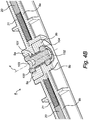
- Figure 2 shows that supports (5a, 5b) of aid 1 can comprise telescopically extendable parts.
- support 5a which consists of a tube part 50a with a diameter of 18 mm which extends from the proximal outer end 7a to beyond pivoting connection 6, and a tube part 50b with a diameter of 15 mm which is telescopically slidable in tube part 50a and is mounted on the distal spoon element 13a.
- the tube part 50b is provided with three holes 16 at a mutual spacing of 5 cm, and tube part 50a with one opening 17.
- the total adjustment range is hereby 10 cm. If desired, this range can be increased in simple manner by lengthening tube part 50b and adding holes.
- tube part 50b slides into hinge part 6 and the tube part 50a already inserted therein.
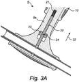
- the two tube parts (50a, 50b) are fixed into position by a locking member formed by a resilient locking pin 20 which is shown in more detail in figures 3A-3C .
- Due to the method of length adjustment tube part 50b with spoon element 13a can be mounted in only one way. This is also the case for the tube parts of the other support (5b).
- the orientation of spoon elements (13a, 13b) relative to each other is hereby always correct, and a user need not take account of left or right.
- Locking pin 20 is situated in transverse profiles (9a, 9b) of pivoting connection 6 and is held by means of a spring 21 in a locked position, wherein locking pin 20 engages through opening 17 of support part 50a and an opening 16 of support part 50b.
- Locking pin 20 can be moved in the direction 22 and fixed in an unlocked position by a catch 23 which is connected to locking pin 20 by means of fixing pin 24.
- Locking catch 23 lies inside profile 9a and does not therefore protrude, thereby limiting the risk of undesired unlocking.
- Locking catch 23 can be gripped with thumb and index finger and displaced counter to the spring pressure produced by spring 21.
- the biased spring pressure typically amounts to about 0.5 kg in locked position. For unlocking purposes a total spring pressure of about 1 kg has to be overcome.
- support 5a That described above for support 5a also applies to support 5b.
- aid 1 can be manufactured from any material suitable for the purpose.
- Components such as the spoon elements (13a, 13b), hinge part 6 and (auxiliary) handles (18a, 18b, 19a, 19b) are thus preferably made by injection moulding of glass fibre-reinforced plastic.
- Other components such as the fixing pins, the locking catch and the spring are preferably made of steel, while supports (5a, 5b) are typically made of anodized aluminium.
- aid 1 consists of pre-assembled components, it can be easily assembled or disassembled by a user.
- the division into components further ensures that aid 1 can be packaged, shipped and stored in compact form. This moreover provides the option of length adjustment in accordance with build, height and reach, and adjustment of the opening range of an elastic stocking arranged on the aid.
- An elastic stocking can be pulled on as follows using aid 1. Aid 1 is closed at the distal outer end (8a, 8b) and then placed upside down, with the handles (18a, 18b) downward (where supports (5a, 5b) are thus spaced apart) transversely on a ground surface between the legs of the user. If desired, the user can place one foot on a handle (18a, 18b) in order to stabilize aid 1. The elastic stocking is then clamped with the seam (or rear side) directed upward at the heel between the second tensioning elements (14a, 14b), which point upward in the upside down position. The upper edge of the elastic stocking is then folded back over the other (first) tensioning elements (15a, 15b). This does not involve any appreciable tension.
- An elongate sliding strip of a flexible, smooth material, for instance spinnaker cloth, can then also be placed with a relatively short outer end in the elastic stocking, wherein the remaining, relatively long part is likewise clamped between the second tensioning elements (14a, 14b) together with the heel part of the elastic stocking.
- Aid 1 is then turned over again and placed in the position as shown in figure 1 .
- the most proximal handles (18a, 18b) of aid 1 are then gripped by the user and moved toward each other (opposite to the directions (11a, 11b)). This movement places the elastic stocking under tension and widens the opening for a foot of the user.
- the first tensioning elements (15a, 15b) over which the elastic stocking is tensioned are set down on the ground close to the foot, in front of the toes, after which the foot is pushed into the opening of the elastic stocking.
- the opening can be enlarged here by moving the handles (18a, 18b) further apart.
- Aid 1 is optionally tilted just slightly about its longitudinal axis at the moment that the narrow portion of the elastic stocking, which is situated just above the ankles, has to be pulled over the heel/instep part of the user. This manoeuvre makes the opening easier to adjust in the width to the heel/instep part.
- the elastic stocking is pulled further upward, wherein supports (5a, 5b) are then gripped on the intermediate auxiliary handles (19a, 19b).
- the same aid 1 can likewise be used for the purpose of pulling off an elastic stocking.
- the distal (second) tensioning elements (14a, 14b) point downward here, and supports (5a, 5b) rest along the body with the proximal handles (18a, 18b) on or above the shoulders.
- the second tensioning elements (14a, 14b) are pushed into the elastic stocking on either side of the lower leg via the top side of the elastic stocking.
- the elastic stocking is then pushed downward using handles (18a, 18b, 19a, 19b) of supports (5a, 5b).
- a (therapeutic) elastic stocking can be pulled on and off as described in simple manner using little force and small movements. The aid is easy to handle, light in weight and, owing to the modular structure, saves storage space.
- the opening of an elastic stocking can be made larger or smaller by the scissor action of the supports.
- Arranging an elastic stocking over the tensioning elements is also simple, in contrast to known aids where the elastic stocking has to be tensioned over a bracket or pushed into a ring, or wherein the elastic stocking has to be slid over stationary rubber balls. Because the spoon elements take an ergonomic form and are covered with relatively smooth rubber, these elements cause less friction and do not press painfully into the skin of a user. The aid is further adjustable in the length, which increases the convenience of use and the flexibility thereof.
Landscapes
- Orthopedics, Nursing, And Contraception (AREA)
Claims (15)
- Hilfsmittel zum An- und Ausziehen eines elastischen Strumpfes von einem Bein, wobei das Hilfsmittel zwei gegenseitig gekoppelte längliche Träger aufweist, jeder mit einem proximalen Griffende und einem distalen Spannende, wobei die Kopplung eine Schwenkverbindung umfasst, die zwischen den beiden Außenenden angeordnet ist und mit der die Träger in der Art von Scheren in einer Querrichtung bewegt werden können, und wobei die Träger jeweils ein erstes Spannelement zwischen dem Spannende und der Schwenkverbindung aufweisen, wobei die Elemente ein benachbart angeordnetes Paar bilden, über das ein Strumpf angeordnet werden kann, wobei die Schwenkverbindung in einem Querabstand von den Trägern mittels Abstandshaltern angeordnet sind, dadurch gekennzeichnet, dass
die Abstandshalter einen Handgriff aufweisen, wobei die Schwenkverbindung mit einer flexiblen Hülse abgedeckt ist, die den Handgriff bildet. - Hilfsmittel nach Anspruch 1, wobei sich die Abstandshalter im Wesentlichen rechtwinklig zu den Trägern erstrecken und ihre kombinierte Länge mindestens 10 cm beträgt.
- Hilfsmittel nach Anspruch 1 oder 2, wobei der Abstand von der Schwenkverbindung zu dem distalen Spannende zwischen 1/5 und ½ der Gesamtlänge der Träger beträgt.
- Hilfsmittel nach einem der vorstehenden Ansprüche, wobei die Schwenkverbindung in einem Abstand von 20 bis 35 cm von dem distalen Spannende angeordnet ist.
- Hilfsmittel nach einem der vorstehenden Ansprüche, wobei die Träger jeweils ein zweites Spannelement an dem distalen Spannende aufweisen, wobei die Elemente ein benachbart angeordnetes Paar bilden, über das ein Strumpf angeordnet werden kann.
- Hilfsmittel nach einem der vorstehenden Ansprüche, wobei die Spannelemente in einem Abstand von den Trägern in einer Sagittalebene des Hilfsmittels mittels Abstandshaltern angeordnet sind.
- Hilfsmittel nach Anspruch 6 wobei die Abstandshalter der ersten Spannelemente in der proximalen Richtung verlaufen und die Abstandshalter der zweiten Spannelemente in der distalen Richtung.
- Hilfsmittel nach einem der Ansprüche 5-7, wobei die ersten Spannelemente in Richtung auf das proximale Außenende gerichtet sind und die zweiten Spannelemente zu dem distalen Spannende, sodass sie S-förmige Löffelelemente bilden.
- Hilfsmittel nach Anspruch 6 oder 7, wobei jeder Träger an dem distalen Spannende ein Löffelelement aufweist, dessen Außenende die Spannelemente bilden und dessen Mittelteil den Abstandshalter bildet.
- Hilfsmittel nach einem der vorstehenden Ansprüche, wobei die Träger teleskopisch ausfahrbare Teile aufweisen, die mittels eines Sperrelements fixiert werden können.
- Hilfsmittel nach Anspruch 10, wobei die Trägerteile Öffnungen in ihrer Umfangsfläche aufweisen und das Sperrelement einen Sperrstift aufweist, der mittels einer Feder in einer gesperrten Position gehalten wird, in der der Sperrstift in eine Öffnung eines Trägerteils eingreift und der mittels eines Hakens in eine entsperrte Position gebracht werden kann, in der der Sperrstift die relevante Öffnungen frei macht.
- Hilfsmittel nach einem der vorstehenden Ansprüche, wobei die Träger jeweils einen Handgriff aufweisen, der sich in einer Sagittalebene an den proximalen Griffenden erstreckt.
- Hilfsmittel nach einem der vorstehenden Ansprüche, wobei die Träger jeweils einen Hilfsgriff aufweisen, der sich in einer Sagittalebene zwischen der Schwenkverbindung und den proximalen Griffenden erstreckt.
- Verfahren zum Anziehen eines elastischen Strumpfs mita) Vorsehen eines Hilfsmittels nach einem der vorstehenden Ansprüche,b) Koppeln der ersten Spannelemente und eines elastischen Strumpfs durch Falten des elastischen Strumpfs zurück von seiner oberen Kante über die ersten Spannelemente, wodurch eine Öffnung für einen Fuß gebildet wird,c) Bewegen des Hilfsmittels in eine Spannposition, in der die Griffenden proximal relativ zu dem Benutzer sind und die Spannelemente distal,d) Aufweiten der Öffnung durch Bewegen der proximalen Außenenden des Trägers zueinander und Einbringen des Fußes in die Öffnung,g) Bewegen des Hilfsmittels in der proximalen Richtung, wodurch der elastischen Strumpf zusammen mit den ersten Spannelementen des Unterschenkels zum Knie und in die gewünschte Position bewegt wird, unde) Entkoppeln der ersten Spanneinrichtung und des elastischen Strumpfs.
- Verfahren zum Ausziehen eines elastischen Strumpfs mita) Vorsehen eines Hilfsmittels nach einem der Ansprüche 1-13,b) Koppeln der zweiten Spannelemente und eines elastischen Strumpfs, der um ein Bein angeordnet ist, durch Platzieren der zweiten Spannelemente unter einer Oberkante des elastischen Strumpfs, wodurch eine Umfangsöffnung zwischen dem Strumpf und dem Bein gebildet wird,c) Bewegen des Hilfsmittels in der distalen Richtung, wodurch der elastischen Strumpf zusammen mit den zweiten Spannelementen entlang des Unterschenkels zum Fuß und in die gewünschte Position bewegt wird,d) Aufweiten der Umfangsöffnung durch Bewegen der proximalen Außenenden der Träger zueinander,e) Weiteres Abschälen des elastischen Strumpfs über den Fuß, bis er entfernt ist, undf) Entkoppeln der zweiten Spanneinrichtungen und des elastischen Strumpfs.
Applications Claiming Priority (2)
| Application Number | Priority Date | Filing Date | Title |
|---|---|---|---|
| NL2009477A NL2009477C2 (nl) | 2012-09-17 | 2012-09-17 | Hulpmiddel voor het aan- en uittrekken van elastische kousen. |
| PCT/NL2013/050667 WO2014042536A1 (en) | 2012-09-17 | 2013-09-16 | Aid for pulling elastic stockings on and off |
Publications (3)
| Publication Number | Publication Date |
|---|---|
| EP2895035A1 EP2895035A1 (de) | 2015-07-22 |
| EP2895035B1 true EP2895035B1 (de) | 2017-11-29 |
| EP2895035B8 EP2895035B8 (de) | 2018-02-07 |
Family
ID=47146596
Family Applications (1)
| Application Number | Title | Priority Date | Filing Date |
|---|---|---|---|
| EP13767151.7A Active EP2895035B8 (de) | 2012-09-17 | 2013-09-16 | Hilfe zum an- und ausziehen elastischer strümpfe |
Country Status (3)
| Country | Link |
|---|---|
| EP (1) | EP2895035B8 (de) |
| NL (1) | NL2009477C2 (de) |
| WO (1) | WO2014042536A1 (de) |
Family Cites Families (6)
| Publication number | Priority date | Publication date | Assignee | Title |
|---|---|---|---|---|
| US4093298A (en) * | 1977-01-17 | 1978-06-06 | The Raymond Lee Organization, Inc. | Compressor tongs |
| NL8902619A (nl) | 1989-10-23 | 1991-05-16 | Stichting Medische Technologie | Hulpmiddel voor het aantrekken van therapeutische elastische kousen. |
| US5249720A (en) * | 1992-05-01 | 1993-10-05 | White Allen A | Tool for facilitating application of elastic stockings |
| US20040060950A1 (en) * | 2002-09-26 | 2004-04-01 | Goff Lyle Valentine | Socker |
| US20100264678A1 (en) * | 2009-04-20 | 2010-10-21 | Rolling Jr Joseph E | Introduction of the panther multi task tool |
| ITGE20100096A1 (it) * | 2010-09-06 | 2010-12-06 | Pietrino Forfori | Dispositivo infila calze elastiche |
-
2012
- 2012-09-17 NL NL2009477A patent/NL2009477C2/nl active
-
2013
- 2013-09-16 EP EP13767151.7A patent/EP2895035B8/de active Active
- 2013-09-16 WO PCT/NL2013/050667 patent/WO2014042536A1/en not_active Ceased
Also Published As
| Publication number | Publication date |
|---|---|
| EP2895035A1 (de) | 2015-07-22 |
| WO2014042536A1 (en) | 2014-03-20 |
| EP2895035B8 (de) | 2018-02-07 |
| NL2009477C2 (nl) | 2014-03-20 |
Similar Documents
| Publication | Publication Date | Title |
|---|---|---|
| EP2104481B1 (de) | Biomechanische abgeleitete stütze | |
| US8708363B1 (en) | Folding walker | |
| JP7235250B2 (ja) | 可撓性の脚部支持膜、脚部支持フレーム、並びに移動式患者直立起立補助器具 | |
| US11426323B2 (en) | Multi-functional foot crutch | |
| US9386875B2 (en) | Combination shoe horn and sock donning and doffing apparatus | |
| US10278887B2 (en) | Crutch and sitting device | |
| US10918233B2 (en) | Device for wearing socks, and method of using such device | |
| US20090114257A1 (en) | Handle and a Walking Aid Incorporating the Same | |
| US20210212880A1 (en) | Crutch and sitting device | |
| US8047216B2 (en) | Standing aid | |
| WO2017083222A1 (en) | Mobility assistance device | |
| EP2895035B1 (de) | Hilfe zum an- und ausziehen elastischer strümpfe | |
| CN211750863U (zh) | 一种新型助行器 | |
| CN210785275U (zh) | 足踝骨科医疗康复辅助步行器 | |
| EP3533362B1 (de) | Hilfsvorrichtung zum an- und ausziehen von kompressionssocken | |
| US12145025B2 (en) | Extremity flexion and extension exerciser devices | |
| KR102876900B1 (ko) | 양말 착탈 보조장치 | |
| CN204446222U (zh) | 一种o型腿辅助矫正器 | |
| CA2543217C (en) | Pressure off knee brace | |
| AU2013101310A4 (en) | Apparatus for stretching | |
| AU2005281443A1 (en) | A handle and a walking aid incorporating the same | |
| AU2014210608A1 (en) | A handle and a walking aid incorporating the same | |
| ZA200702948B (en) | A handle and a walking aid incorporating the same | |
| CZ2006146A3 (cs) | Nástavec na francouzské berle |
Legal Events
| Date | Code | Title | Description |
|---|---|---|---|
| PUAI | Public reference made under article 153(3) epc to a published international application that has entered the european phase |
Free format text: ORIGINAL CODE: 0009012 |
|
| 17P | Request for examination filed |
Effective date: 20150416 |
|
| AK | Designated contracting states |
Kind code of ref document: A1 Designated state(s): AL AT BE BG CH CY CZ DE DK EE ES FI FR GB GR HR HU IE IS IT LI LT LU LV MC MK MT NL NO PL PT RO RS SE SI SK SM TR |
|
| AX | Request for extension of the european patent |
Extension state: BA ME |
|
| DAX | Request for extension of the european patent (deleted) | ||
| GRAP | Despatch of communication of intention to grant a patent |
Free format text: ORIGINAL CODE: EPIDOSNIGR1 |
|
| INTG | Intention to grant announced |
Effective date: 20170720 |
|
| GRAS | Grant fee paid |
Free format text: ORIGINAL CODE: EPIDOSNIGR3 |
|
| GRAA | (expected) grant |
Free format text: ORIGINAL CODE: 0009210 |
|
| AK | Designated contracting states |
Kind code of ref document: B1 Designated state(s): AL AT BE BG CH CY CZ DE DK EE ES FI FR GB GR HR HU IE IS IT LI LT LU LV MC MK MT NL NO PL PT RO RS SE SI SK SM TR |
|
| REG | Reference to a national code |
Ref country code: CH Ref legal event code: EP |
|
| REG | Reference to a national code |
Ref country code: AT Ref legal event code: REF Ref document number: 949601 Country of ref document: AT Kind code of ref document: T Effective date: 20171215 Ref country code: CH Ref legal event code: NV Representative=s name: ARNOLD AND SIEDSMA AG, CH |
|
| RAP2 | Party data changed (patent owner data changed or rights of a patent transferred) |
Owner name: HANDYCARE HOLDING B.V. |
|
| REG | Reference to a national code |
Ref country code: IE Ref legal event code: FG4D |
|
| REG | Reference to a national code |
Ref country code: DE Ref legal event code: R096 Ref document number: 602013030124 Country of ref document: DE |
|
| REG | Reference to a national code |
Ref country code: NL Ref legal event code: FP |
|
| REG | Reference to a national code |
Ref country code: LT Ref legal event code: MG4D |
|
| REG | Reference to a national code |
Ref country code: AT Ref legal event code: MK05 Ref document number: 949601 Country of ref document: AT Kind code of ref document: T Effective date: 20171129 |
|
| PG25 | Lapsed in a contracting state [announced via postgrant information from national office to epo] |
Ref country code: ES Free format text: LAPSE BECAUSE OF FAILURE TO SUBMIT A TRANSLATION OF THE DESCRIPTION OR TO PAY THE FEE WITHIN THE PRESCRIBED TIME-LIMIT Effective date: 20171129 Ref country code: LT Free format text: LAPSE BECAUSE OF FAILURE TO SUBMIT A TRANSLATION OF THE DESCRIPTION OR TO PAY THE FEE WITHIN THE PRESCRIBED TIME-LIMIT Effective date: 20171129 Ref country code: NO Free format text: LAPSE BECAUSE OF FAILURE TO SUBMIT A TRANSLATION OF THE DESCRIPTION OR TO PAY THE FEE WITHIN THE PRESCRIBED TIME-LIMIT Effective date: 20180228 Ref country code: FI Free format text: LAPSE BECAUSE OF FAILURE TO SUBMIT A TRANSLATION OF THE DESCRIPTION OR TO PAY THE FEE WITHIN THE PRESCRIBED TIME-LIMIT Effective date: 20171129 Ref country code: SE Free format text: LAPSE BECAUSE OF FAILURE TO SUBMIT A TRANSLATION OF THE DESCRIPTION OR TO PAY THE FEE WITHIN THE PRESCRIBED TIME-LIMIT Effective date: 20171129 |
|
| PG25 | Lapsed in a contracting state [announced via postgrant information from national office to epo] |
Ref country code: HR Free format text: LAPSE BECAUSE OF FAILURE TO SUBMIT A TRANSLATION OF THE DESCRIPTION OR TO PAY THE FEE WITHIN THE PRESCRIBED TIME-LIMIT Effective date: 20171129 Ref country code: BG Free format text: LAPSE BECAUSE OF FAILURE TO SUBMIT A TRANSLATION OF THE DESCRIPTION OR TO PAY THE FEE WITHIN THE PRESCRIBED TIME-LIMIT Effective date: 20180228 Ref country code: LV Free format text: LAPSE BECAUSE OF FAILURE TO SUBMIT A TRANSLATION OF THE DESCRIPTION OR TO PAY THE FEE WITHIN THE PRESCRIBED TIME-LIMIT Effective date: 20171129 Ref country code: AT Free format text: LAPSE BECAUSE OF FAILURE TO SUBMIT A TRANSLATION OF THE DESCRIPTION OR TO PAY THE FEE WITHIN THE PRESCRIBED TIME-LIMIT Effective date: 20171129 Ref country code: GR Free format text: LAPSE BECAUSE OF FAILURE TO SUBMIT A TRANSLATION OF THE DESCRIPTION OR TO PAY THE FEE WITHIN THE PRESCRIBED TIME-LIMIT Effective date: 20180301 Ref country code: RS Free format text: LAPSE BECAUSE OF FAILURE TO SUBMIT A TRANSLATION OF THE DESCRIPTION OR TO PAY THE FEE WITHIN THE PRESCRIBED TIME-LIMIT Effective date: 20171129 |
|
| PG25 | Lapsed in a contracting state [announced via postgrant information from national office to epo] |
Ref country code: SK Free format text: LAPSE BECAUSE OF FAILURE TO SUBMIT A TRANSLATION OF THE DESCRIPTION OR TO PAY THE FEE WITHIN THE PRESCRIBED TIME-LIMIT Effective date: 20171129 Ref country code: CZ Free format text: LAPSE BECAUSE OF FAILURE TO SUBMIT A TRANSLATION OF THE DESCRIPTION OR TO PAY THE FEE WITHIN THE PRESCRIBED TIME-LIMIT Effective date: 20171129 Ref country code: DK Free format text: LAPSE BECAUSE OF FAILURE TO SUBMIT A TRANSLATION OF THE DESCRIPTION OR TO PAY THE FEE WITHIN THE PRESCRIBED TIME-LIMIT Effective date: 20171129 Ref country code: CY Free format text: LAPSE BECAUSE OF FAILURE TO SUBMIT A TRANSLATION OF THE DESCRIPTION OR TO PAY THE FEE WITHIN THE PRESCRIBED TIME-LIMIT Effective date: 20171129 Ref country code: EE Free format text: LAPSE BECAUSE OF FAILURE TO SUBMIT A TRANSLATION OF THE DESCRIPTION OR TO PAY THE FEE WITHIN THE PRESCRIBED TIME-LIMIT Effective date: 20171129 |
|
| REG | Reference to a national code |
Ref country code: DE Ref legal event code: R097 Ref document number: 602013030124 Country of ref document: DE |
|
| PG25 | Lapsed in a contracting state [announced via postgrant information from national office to epo] |
Ref country code: RO Free format text: LAPSE BECAUSE OF FAILURE TO SUBMIT A TRANSLATION OF THE DESCRIPTION OR TO PAY THE FEE WITHIN THE PRESCRIBED TIME-LIMIT Effective date: 20171129 Ref country code: PL Free format text: LAPSE BECAUSE OF FAILURE TO SUBMIT A TRANSLATION OF THE DESCRIPTION OR TO PAY THE FEE WITHIN THE PRESCRIBED TIME-LIMIT Effective date: 20171129 Ref country code: IT Free format text: LAPSE BECAUSE OF FAILURE TO SUBMIT A TRANSLATION OF THE DESCRIPTION OR TO PAY THE FEE WITHIN THE PRESCRIBED TIME-LIMIT Effective date: 20171129 Ref country code: SM Free format text: LAPSE BECAUSE OF FAILURE TO SUBMIT A TRANSLATION OF THE DESCRIPTION OR TO PAY THE FEE WITHIN THE PRESCRIBED TIME-LIMIT Effective date: 20171129 |
|
| REG | Reference to a national code |
Ref country code: FR Ref legal event code: PLFP Year of fee payment: 6 |
|
| PLBE | No opposition filed within time limit |
Free format text: ORIGINAL CODE: 0009261 |
|
| STAA | Information on the status of an ep patent application or granted ep patent |
Free format text: STATUS: NO OPPOSITION FILED WITHIN TIME LIMIT |
|
| 26N | No opposition filed |
Effective date: 20180830 |
|
| PG25 | Lapsed in a contracting state [announced via postgrant information from national office to epo] |
Ref country code: SI Free format text: LAPSE BECAUSE OF FAILURE TO SUBMIT A TRANSLATION OF THE DESCRIPTION OR TO PAY THE FEE WITHIN THE PRESCRIBED TIME-LIMIT Effective date: 20171129 |
|
| PG25 | Lapsed in a contracting state [announced via postgrant information from national office to epo] |
Ref country code: MC Free format text: LAPSE BECAUSE OF FAILURE TO SUBMIT A TRANSLATION OF THE DESCRIPTION OR TO PAY THE FEE WITHIN THE PRESCRIBED TIME-LIMIT Effective date: 20171129 |
|
| REG | Reference to a national code |
Ref country code: IE Ref legal event code: MM4A |
|
| PG25 | Lapsed in a contracting state [announced via postgrant information from national office to epo] |
Ref country code: LU Free format text: LAPSE BECAUSE OF NON-PAYMENT OF DUE FEES Effective date: 20180916 |
|
| PG25 | Lapsed in a contracting state [announced via postgrant information from national office to epo] |
Ref country code: IE Free format text: LAPSE BECAUSE OF NON-PAYMENT OF DUE FEES Effective date: 20180916 |
|
| PG25 | Lapsed in a contracting state [announced via postgrant information from national office to epo] |
Ref country code: MT Free format text: LAPSE BECAUSE OF NON-PAYMENT OF DUE FEES Effective date: 20180916 |
|
| PG25 | Lapsed in a contracting state [announced via postgrant information from national office to epo] |
Ref country code: TR Free format text: LAPSE BECAUSE OF FAILURE TO SUBMIT A TRANSLATION OF THE DESCRIPTION OR TO PAY THE FEE WITHIN THE PRESCRIBED TIME-LIMIT Effective date: 20171129 |
|
| PG25 | Lapsed in a contracting state [announced via postgrant information from national office to epo] |
Ref country code: PT Free format text: LAPSE BECAUSE OF FAILURE TO SUBMIT A TRANSLATION OF THE DESCRIPTION OR TO PAY THE FEE WITHIN THE PRESCRIBED TIME-LIMIT Effective date: 20171129 |
|
| PG25 | Lapsed in a contracting state [announced via postgrant information from national office to epo] |
Ref country code: HU Free format text: LAPSE BECAUSE OF FAILURE TO SUBMIT A TRANSLATION OF THE DESCRIPTION OR TO PAY THE FEE WITHIN THE PRESCRIBED TIME-LIMIT; INVALID AB INITIO Effective date: 20130916 Ref country code: MK Free format text: LAPSE BECAUSE OF NON-PAYMENT OF DUE FEES Effective date: 20171129 |
|
| PG25 | Lapsed in a contracting state [announced via postgrant information from national office to epo] |
Ref country code: AL Free format text: LAPSE BECAUSE OF FAILURE TO SUBMIT A TRANSLATION OF THE DESCRIPTION OR TO PAY THE FEE WITHIN THE PRESCRIBED TIME-LIMIT Effective date: 20171129 Ref country code: IS Free format text: LAPSE BECAUSE OF FAILURE TO SUBMIT A TRANSLATION OF THE DESCRIPTION OR TO PAY THE FEE WITHIN THE PRESCRIBED TIME-LIMIT Effective date: 20180329 |
|
| P01 | Opt-out of the competence of the unified patent court (upc) registered |
Effective date: 20230518 |
|
| PGFP | Annual fee paid to national office [announced via postgrant information from national office to epo] |
Ref country code: CH Payment date: 20241002 Year of fee payment: 12 |
|
| REG | Reference to a national code |
Ref country code: CH Ref legal event code: U11 Free format text: ST27 STATUS EVENT CODE: U-0-0-U10-U11 (AS PROVIDED BY THE NATIONAL OFFICE) Effective date: 20251001 |
|
| PGFP | Annual fee paid to national office [announced via postgrant information from national office to epo] |
Ref country code: DE Payment date: 20250929 Year of fee payment: 13 |
|
| PGFP | Annual fee paid to national office [announced via postgrant information from national office to epo] |
Ref country code: NL Payment date: 20250926 Year of fee payment: 13 |
|
| PGFP | Annual fee paid to national office [announced via postgrant information from national office to epo] |
Ref country code: BE Payment date: 20250929 Year of fee payment: 13 Ref country code: GB Payment date: 20250929 Year of fee payment: 13 |
|
| PGFP | Annual fee paid to national office [announced via postgrant information from national office to epo] |
Ref country code: FR Payment date: 20250925 Year of fee payment: 13 |