EP3515263B1 - Vorrichtung zum anziehen von socken - Google Patents
Vorrichtung zum anziehen von socken Download PDFInfo
- Publication number
- EP3515263B1 EP3515263B1 EP17852547.3A EP17852547A EP3515263B1 EP 3515263 B1 EP3515263 B1 EP 3515263B1 EP 17852547 A EP17852547 A EP 17852547A EP 3515263 B1 EP3515263 B1 EP 3515263B1
- Authority
- EP
- European Patent Office
- Prior art keywords
- caddy
- foot
- sock
- user
- semi
- Prior art date
- Legal status (The legal status is an assumption and is not a legal conclusion. Google has not performed a legal analysis and makes no representation as to the accuracy of the status listed.)
- Not-in-force
Links
- 210000002683 foot Anatomy 0.000 claims description 131
- 238000000034 method Methods 0.000 claims description 47
- 230000008569 process Effects 0.000 claims description 36
- 230000007246 mechanism Effects 0.000 claims description 32
- 210000003423 ankle Anatomy 0.000 claims description 21
- 210000003371 toe Anatomy 0.000 claims description 14
- 238000004873 anchoring Methods 0.000 claims description 4
- 210000002414 leg Anatomy 0.000 description 31
- 230000006835 compression Effects 0.000 description 9
- 238000007906 compression Methods 0.000 description 9
- 230000008901 benefit Effects 0.000 description 7
- 230000000670 limiting effect Effects 0.000 description 6
- 238000005452 bending Methods 0.000 description 5
- 238000006073 displacement reaction Methods 0.000 description 5
- 210000003127 knee Anatomy 0.000 description 5
- 230000004048 modification Effects 0.000 description 5
- 238000012986 modification Methods 0.000 description 5
- 201000006938 muscular dystrophy Diseases 0.000 description 5
- 210000002435 tendon Anatomy 0.000 description 5
- 210000003205 muscle Anatomy 0.000 description 4
- 230000006872 improvement Effects 0.000 description 3
- 238000003780 insertion Methods 0.000 description 3
- 239000000463 material Substances 0.000 description 3
- 230000002829 reductive effect Effects 0.000 description 3
- 230000003068 static effect Effects 0.000 description 3
- 238000001356 surgical procedure Methods 0.000 description 3
- 238000007792 addition Methods 0.000 description 2
- 201000010099 disease Diseases 0.000 description 2
- 208000037265 diseases, disorders, signs and symptoms Diseases 0.000 description 2
- 230000003203 everyday effect Effects 0.000 description 2
- 230000037431 insertion Effects 0.000 description 2
- 230000004044 response Effects 0.000 description 2
- 238000006467 substitution reaction Methods 0.000 description 2
- 210000000689 upper leg Anatomy 0.000 description 2
- 210000003462 vein Anatomy 0.000 description 2
- 229920000742 Cotton Polymers 0.000 description 1
- 208000001034 Frostbite Diseases 0.000 description 1
- 239000004677 Nylon Substances 0.000 description 1
- 208000008589 Obesity Diseases 0.000 description 1
- 229920002334 Spandex Polymers 0.000 description 1
- 208000027418 Wounds and injury Diseases 0.000 description 1
- 238000009825 accumulation Methods 0.000 description 1
- NIXOWILDQLNWCW-UHFFFAOYSA-N acrylic acid group Chemical group C(C=C)(=O)O NIXOWILDQLNWCW-UHFFFAOYSA-N 0.000 description 1
- 239000008280 blood Substances 0.000 description 1
- 210000004369 blood Anatomy 0.000 description 1
- 230000008859 change Effects 0.000 description 1
- 238000010276 construction Methods 0.000 description 1
- 230000008878 coupling Effects 0.000 description 1
- 238000010168 coupling process Methods 0.000 description 1
- 238000005859 coupling reaction Methods 0.000 description 1
- 230000002354 daily effect Effects 0.000 description 1
- 230000006378 damage Effects 0.000 description 1
- 230000003247 decreasing effect Effects 0.000 description 1
- 230000007812 deficiency Effects 0.000 description 1
- 238000013461 design Methods 0.000 description 1
- 230000003292 diminished effect Effects 0.000 description 1
- 239000013013 elastic material Substances 0.000 description 1
- 239000004744 fabric Substances 0.000 description 1
- 238000010438 heat treatment Methods 0.000 description 1
- 210000001624 hip Anatomy 0.000 description 1
- 208000014674 injury Diseases 0.000 description 1
- 230000003993 interaction Effects 0.000 description 1
- 239000007788 liquid Substances 0.000 description 1
- 230000007774 longterm Effects 0.000 description 1
- 238000012423 maintenance Methods 0.000 description 1
- 238000004519 manufacturing process Methods 0.000 description 1
- 230000007721 medicinal effect Effects 0.000 description 1
- 229920001778 nylon Polymers 0.000 description 1
- 235000020824 obesity Nutrition 0.000 description 1
- 230000036961 partial effect Effects 0.000 description 1
- 229920000728 polyester Polymers 0.000 description 1
- 230000035935 pregnancy Effects 0.000 description 1
- 230000009467 reduction Effects 0.000 description 1
- 239000004759 spandex Substances 0.000 description 1
- 210000000278 spinal cord Anatomy 0.000 description 1
- 230000000087 stabilizing effect Effects 0.000 description 1
- 210000004243 sweat Anatomy 0.000 description 1
- 230000009424 thromboembolic effect Effects 0.000 description 1
- 239000013598 vector Substances 0.000 description 1
- -1 wool Polymers 0.000 description 1
- 210000002268 wool Anatomy 0.000 description 1
Images


Classifications
-
- A—HUMAN NECESSITIES
- A47—FURNITURE; DOMESTIC ARTICLES OR APPLIANCES; COFFEE MILLS; SPICE MILLS; SUCTION CLEANERS IN GENERAL
- A47G—HOUSEHOLD OR TABLE EQUIPMENT
- A47G25/00—Household implements used in connection with wearing apparel; Dress, hat or umbrella holders
- A47G25/90—Devices for domestic use for assisting in putting-on or pulling-off clothing, e.g. stockings or trousers
- A47G25/905—Devices for domestic use for assisting in putting-on or pulling-off clothing, e.g. stockings or trousers for stockings
-
- A—HUMAN NECESSITIES
- A47—FURNITURE; DOMESTIC ARTICLES OR APPLIANCES; COFFEE MILLS; SPICE MILLS; SUCTION CLEANERS IN GENERAL
- A47G—HOUSEHOLD OR TABLE EQUIPMENT
- A47G25/00—Household implements used in connection with wearing apparel; Dress, hat or umbrella holders
- A47G25/90—Devices for domestic use for assisting in putting-on or pulling-off clothing, e.g. stockings or trousers
Definitions
- the present invention relates to the field of socks, as well as aids for daily living and aids for wearing socks.
- a sock is an item of clothing worn on the foot.
- socks may absorb sweat and perspiration from the feet.
- socks may provide comfort and heating to the feet, and may decrease the risk of frostbite. Socks are often worn as an intermediary layer between the bare feet and a pair of shoes, thereby providing additional comfort to the wearer.
- Socks may be manufactured from various materials, for example, cotton, wool, nylon, acrylic, polyester, spandex, silk, and/or other material(s). Socks may be manufactured in different sizes or lengths, for example, ankle socks, knee-high socks, over-the-knee socks, or the like.
- An example of an apparatus for wearing socks is known from US 9,119,494 B2 .
- Said apparatus includes a handle in the form of a pole that is fixedly connected to a base plate of the apparatus to actuate a caddy during donning of socks.
- the present invention may include, for example, devices for wearing socks, or devices which may assist a person to put-on or to wear or to don a sock.
- the present invention may provide other and/or additional benefits and/or advantages.
- Embodiments of the present invention may comprise devices for wearing socks; including the device(s) that are shown in any one of Figs. 1 to 31C , and/or that are discussed herein with reference to any one of Figs. 1 to 31C , as well as modifications and/or improvements of such devices as described herein.
- the devices of the present invention may comprise, any one or more features or components that are shown in Figs. 1 to 31C , and/or any one or more features or components that are discussed with reference to any one of Figs. 1 to 31C , and/or any other components, additions, substitutions, or modifications that are described herein with reference to Figs. 32 to 37H , and some or all of such components or units may be utilized in combination and/or in cooperation with each other, in accordance with the present invention.
- sock as used herein may include any suitable type of sock or foot apparel, or any type of garment or article-of-clothing which is intended for wearing on the foot.
- Applicants have realized that some people may have difficulty in wearing (or donning) socks by themselves.
- Such persons may include, for example, disabled persons, handicapped or invalid persons, persons that suffer from a particular disease or medical condition, children, senior citizens, old persons, persons that are tired or exhausted, persons that have difficulty bending down and/or reaching their toes and/or reaching their feet and/or reaching their ankles, or the like.
- other types of users who may not suffer from any limiting condition, may still benefit from a device which may assist user to put-on socks, and which may obviate the need to bend-down or to reach-down in order to put on the socks.
- the present invention relates to the field of invalid aids and appliances. More particularly, the invention relates to an apparatus and method for self-serve use by invalids or handicapped persons, and especially for use by invalids with amputated or disabled arms, or by people having muscular dystrophy or tendon problems, permitting a person to don his sock without any assistance.
- Applicants have realized that people with various physically limiting conditions may have difficulty in dressing themselves unassisted by a second individual, limiting their ability to live independently; this at times contributes to lowered self-esteem and depression.
- Examples of limiting physical conditions that may contribute to such difficulties while properly and comfortably getting dressed may include: pregnancy, obesity, and a diminished range of motion in the back, hip, knee, ankle, or foot; often caused by injury, disease, or surgery.
- Applicants have realized that one special problem for invalids, handicapped persons with amputated or disabled arms, people having muscular dystrophy or tendon problems, or people who are recovering from a surgery, is the donning of socks.
- the present invention seeks to overcome these difficulties by providing a sock donning apparatus which is easy to use and simple in maintenance.
- Some embodiments of the present invention may provide a novel sock donning apparatus and method having many advantages while simultaneously overcoming disadvantages that prior art devices suffer from.
- Some embodiments of the present invention may provide donning apparatus which is of a durable and reliable construction.
- Some embodiments of the present invention may provide a sock donning apparatus which does not require a pulling motion by the user's arm, and/or does not require the user to bend his back or to bend his body, or which require the user to only slightly bend his back and/or his body.
- Some embodiments of the present invention may provide a sock donning apparatus that aids a user who is an invalid, a handicapped person with amputated or disabled arms, a person having muscular dystrophy or tendon problems, a user that is recovering from surgery, or a person with any other limiting physical condition, in putting on socks within a minimal time, without requiring assistance from other person(s), and/or without bending down, and/or without bending his (or her) back, and/or without the need to reach down with the wearer's hand(s) to the wearer's toes or ankles or feet, and/or with reduced or minimal strain on the wearer's body.
- Some embodiments of the present invention may provide a sock donning apparatus which utilizes the elasticity of socks to provide an easy fit for legs (or feet) of different sizes.
- Some embodiments of the present invention may provide a sock donning apparatus which is compatible with socks of different sizes and types.
- Some embodiments of the present invention may provide a sock donning apparatus which may be easily and efficiently manufactured and/or marketed and/or maintained and/or utilized.
- Some embodiments of the present invention may provide a sock donning apparatus which may have a low cost of manufacture with regard to both materials and labor, and which accordingly may have a low cost or reduced cost for consumers.
- the present invention provides apparatus for donning or wearing or putting-on socks (or a single sock; or a single garment typically worn on a foot), comprising a substantially horizontal base, an elongated U-shaped, semi-cylindrical caddy on which a sock positioned inside out is fittable and into an interior of which a foot is insertable, and a tilt unit coupled to said caddy and pivotally connected to a head portion of said base.
- the sock is kept open prior to a sock donning operation to facilitate insertion of a foot into the sock.
- the pivotally connected tilt unit advantageously supports a pushing motion of the leg and/or of the foot, and does not require a pulling motion of an arm of the user, as has been practiced heretofore in some prior art devices.
- the base may be T-shaped so as to be configured by an elongated main portion and two spaced, forwardly positioned head portions, the tilt unit being insertable within an interspace between said two head portions and pivotally connected to said two head portions by at least one coupled horizontally disposed pin which is substantially perpendicular to said main portion and introducible within a recess formed within a forwardly positioned projection of the tilt unit, allowing the tilt unit and caddy to be tilted about a horizontal axis during a sock donning operation.
- the tilt unit may have a central through-hole through which a part protruding from the caddy and connected with a projection of a flange passes, said through-hole being positioned rearwardly from the projection of the tilt unit, allowing the caddy and flange to be rotated in unison about a vertical axis during the sock donning operation.
- the flange may limit the rotational displacement of the caddy about a central axis of the through-hole.
- An inner face of each of the two head portions may have an upper, substantially straight and unreccesed region, and a lower region which is angularly recessed with respect to said upper region, thereby allowing the flange to rotate for a predetermined angular distance when the caddy is at a rest position until the flange contacts said inner face, yet preventing the flange from rotating when the caddy is tilted.
- the apparatus may further comprise a hook member which is engageable with a stationary or relatively stationary element for providing a reactive force during the sock donning operation.
- the main portion of the base may be hollowed to fixedly receive the hook member, and the hook member may be selectively extendable with respect to the main portion of the base.
- the hook member may comprise an elongated positioning bar formed with a plurality of longitudinally spaced latching grooves, a hook rearwardly extending from said positioning bar, and a spring biased detent pivotally connected to the main portion of the base for selectively engaging one of said grooves.
- the detent may comprise a finger contactable portion for disengaging the detent from the engaged groove, to allow the bar to be repositioned.
- the apparatus may further comprise a pole assembly extending upwardly from one of the head portions, for facilitating manual displacement of the apparatus.
- the pole assembly may comprise a straight pole section and a bent pole section that is movable within a cup attachment fixed to the base, for facilitating apparatus repositioning.
- the present invention further includes a method for donning socks, comprising the steps of, for example: providing an apparatus comprising a substantially horizontal base and an elongated U-shaped, semi-cylindrical caddy movably coupled to said base; fitting a sock in an inside out arrangement over a rearward terminal edge of said caddy; securing said base to a relatively stationary element for providing a reactive force during a sock donning operation while a user is positioned to the rear of said caddy; inserting a foot of the user into the interior of the sock, while said foot applies a moment to said caddy to cause said caddy to pivot and an open end of the sock is gradually slipped off said rearward terminal edge of said caddy; and fully inserting toes of the user into a toe portion of the sock, to cause said caddy to assume a final pivoted position and the sock to be released from said caddy.
- the caddy also may rotate about a substantially vertical axis while the foot is being inserted into the interior of the sock.
- a first apparatus and a second (generally similar or generally identical) apparatus may be positioned forwardly to right and left feet, respectively, and first and second socks are donned on the right and left feet, respectively, thereby, allowing the first and second socks to be donned simultaneously, or concurrently, or in a serial manner (e.g., one after the other), by the same wearer.
- the method may further comprise the steps of: providing a hook member coupled to the base, and affixing said hook member to the relatively stationary element.
- the hook member may be extendable, and the length of the hook member may be set prior to inserting the foot into the interior of the sock.
- a pole assembly extending upwardly from the base may be manipulated or utilized by the user in order to adjust a direction of the caddy relative to a direction of the foot to be inserted into the interior of the sock.
- the pole assembly may comprise a straight pole section, a hand graspable knob fitted from above to said straight pole section, and a bent pole section fitted from below to said straight pole section that is rotatable within a cup attachment fixed to the base, and wherein the user selectively rotates said bent pole section when desired to bring said knob closer or farther away from the relatively stationary element in order to facilitate apparatus repositioning.
- an apparatus for donning (or wearing) a sock may comprise: a substantially horizontal base; an elongated U-shaped, semi-cylindrical caddy on which a sock positioned inside out is fittable and into an interior of which a foot is insertable; and a tilt unit coupled to said caddy and pivotally connected to a head portion of said base.
- the base is T-shaped and is configurable by an elongated main portion and two spaced, forwardly positioned head portions.
- the tilt unit is insertable within an interspace between said two head portions.
- the tilt unit is pivotally connected to said two head portions by at least one coupled horizontally disposed pin which is substantially perpendicular to said main portion.
- the pin is introducible within a recess formed within a forwardly positioned projection of the tilt unit.
- the tilt unit and the caddy are able to be tilted about a horizontal axis during a sock donning operation.
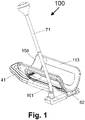
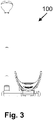
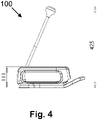
- Fig. 1 illustrates a perspective view of sock donning apparatus 100 from the side, according to some demonstrative embodiments of the present invention.
- Apparatus 100 may comprise a base 101 and an elongated U-shaped (or concave, or convex), semi-cylindrical tube or caddy 113, for foot and/or leg placement (e.g., able to fit or to accommodate therein a human foot) that may be pivotally connected by a tilt unit 62 to base 101.
- a sock intended to be worn by the user is positionable on rounded rearward terminal edge 158 of caddy 113.
- Caddy 113 is shown in a rest position or starting position or initial position.
- Base 101 may be substantially T-shaped or may be generally T-shaped, and its main portion may be hollowed to receive a slidable hook member 41, shown in a retracted position. Extending upwardly from the head or front of base 101 is a pole assembly 71, which may be used to manually displace apparatus 100 to a position that is more convenient to a user during a sock donning (sock wearing, sock putting-on) operation.
- sock donning sock wearing, sock putting-on
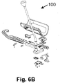
- apparatus 100 is shown in perspective views in Figs. 2A-2B , in a front view in Fig. 3 , in a side view in Fig. 4 , in a top view in Fig. 5 , and in exploded views in Figs. 6A-6B .
- a spring biased detent 52 for selectively engaging hook member 41 in order to set a desired degree of extension from base 101 may be pivotally connected by pin 59 to seats 106 formed in a corresponding protrusion 108 to main portion 110 of base 101.
- Hook member 41 may comprise an elongated positioning bar 43 which may be formed, for example, with a plurality of longitudinally spaced latching grooves 45, and an inclined element 46 considerably thinner than, and extending slightly upwardly from, the longitudinal end of bar 43.
- Inclined element 46 may be able to change direction to define hook 49, which may be engageable with the leg of a chair or other furniture or any other stationary or relatively stationary element that can provide a reactive force (or counter-force) during a sock donning operation, as described herein.
- Detent 52 may have a first rearwardly oriented portion 53 for contacting the upper surface of bar 43 and a second, finger contactable portion 54 extending rearwardly and obliquely from first portion 53.
- a protuberance 57 for engaging a selected groove 45 may extend downwardly from first portion 53, generally at the forward end thereof.
- Second portion 54 may be normally spaced from inclined element 46 of hook element 41. Second portion 54 may be lowered when a finger applies a force thereto, causing protuberance 57 to be disengaged from groove 45 and allowing bar 43 to be displaced to a different longitudinal position with respect to main portion 110 of base 101. When the force is released, detent 52 returns to its original position and once again hook member 41 is fixed to a selected longitudinal position.
- Hook member 41 is shown in a fully retracted position in Figs. 7-11 and in an extended position in Figs. 12-13 ; such that, for example, Fig. 7 shows a top view, Figs. 8-9 show side cross sectional views, Figs. 10 and 12 show side views, and Figs. 11 and 13 show perspective views from the top.
- FIG. 14 An exploded side view of pole assembly 71 is shown in Fig. 14 , and an assembled side view thereof is shown in Fig. 15 .
- a socket 73 may protrude upwardly from head portion 112 of base 101, and may be connected thereto in the manner shown in Figs. 18-19 , which are side cross sectional views.
- a cup attachment 74 is received within socket 73, to which a bent pole section 76 is releasably and movably connectable.
- a straight pole section 78 may be releasably connectable to bent pole section 76, allowing pole assembly 71 to be dismantled as shown in Fig. 16 .
- pole assembly 71 may be moved while received within attachment 74, so that knob 79 will be more to accessible to a user who desires to perform a sock donning operation with the apparatus 100.
- caddy 113 is advantageously able to be both tilted about a horizontal axis and rotated about a vertical axis during a sock donning operation, depending upon the physical capabilities of the leg (or foot) of a user.
- a rectilinear tilt unit 62 may be fitted within the interspace between the two head portions 111 and 112 of base 101.
- a tubular and annular pin 64 introducible through a similarly shaped recess formed within a forwardly positioned projection 67 of tilt unit 62, may be coupled to two opposed pin holders 119 protruding from the inner face of head portions 111 and 112, respectively thereby allowing tilt unit 62 and caddy 113 to pivot about pin 64 when a suitable force is applied by the leg of the user.
- Tilt unit 62 may have a central through-hole 61, through which circular protruding part 118 of caddy 113 located in the vicinity of forward terminal edge 160 passes.
- a circular projection 86 protruding from flange 83 and introducible into through hole 61 may be connected to the bottom face of protruding part 118, e.g., by screws or other suitable connection mechanism; thereby allowing flange 83 and protruding part 118 to rotate in unison about the central axis of through-hole 61 while an outer element of protruding part 118 is in supporting relation with the rim of through-hole 61.
- limited rotation in unison about the central axis of through-hole 61 may be required to allow the user deciding from which side of the apparatus 100 he wished to insert his leg (or his foot) into the sock (which is already slipped over the rearward terminal edge 158 of caddy 113), so as to prevent the user's heel from encountering the leg of the chair.
- Flange 83 may serve as an angular limiter for the rotational displacement of caddy 113 about the central axis of through hole 61.
- Cooperating with flange 83 is inner face 122 of head portions 111 and 112, a lower region of which may be angularly recessed with respect to an upper, substantially straight and unrecessed region thereof. This angular recess may allow flange 83 to rotate when caddy is at the rest position for a predetermined angular distance, e.g., up to 15 or 20 or 30 or 40 degrees in either rotational direction, until the flange contacts inner face 122, yet prevents flange 83 from rotating when caddy 113 is tilted.
- a predetermined angular distance e.g., up to 15 or 20 or 30 or 40 degrees in either rotational direction
- Figs. 20-22 illustrate side views of apparatus 100
- Figs. 23-25 illustrate top views of apparatus 100, showing caddy 113 in three tilted positions with respect to a horizontal axis.
- Figs. 20 and 23 correspond to a rest position
- Figs. 21 and 24 correspond to a middle position or intermediate position
- Figs. 22 and 25 correspond to a fully-opened position.
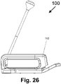
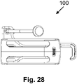
- Figs. 26-27 illustrate side views of apparatus 100 and Figs. 28-29 illustrate top views of apparatus 100, showing caddy 113 in rotated positions with respect to a vertical axis.
- Figs. 26 and 28 correspond to zero yaw position; whereas Figs. 27 and 29 correspond to a full yaw position (e.g., allowing approximately 5 or 7 or 9 or 9.5 or 10 or 12 degrees of yaw to each side).
- hook member 41 may initially be set to a selected longitudinal position that provides optimal comfort to the user, since the user may not be able to bend over (entirely or partially).
- a sock positioned inside out may then be slipped over rearward terminal edge 158 of caddy 113, for example when the caddy is set to a completely vertical position as shown in Fig. 22 , after which the caddy may be set to the rest position shown in Fig. 20 .
- the user or alternatively a caretaker or assistant, may affix hook 49 to the leg of a chair (or other furniture) on top of which the user is sitting, or to any other desired stationary or relatively-stationary element.
- the optimal length may be set once, since the user may repeat the sock donning operations from the same position (e.g., while sitting on a chair or bed or other seat or furniture).
- Pole assembly 71 may be used to conveniently position the apparatus 100, without the need to bend down, until the hook 49 is engaged with the leg of the chair (or of any other relatively stationary element that can provide a reactive force during a sock donning operation). Once the hook 49 is engaged with the leg of the chair, the pole assembly 71 may be used to adjust the direction of caddy 113 to match it to the direction of the first leg.
- the user may further utilize the pole assembly 71 to conveniently disengage the hook 49 from the leg of the chair and to reposition the apparatus 100, until the hook 49 is engaged with another leg of the chair, which may be closer to the second leg of the user.
- the pole assembly 71 may be utilized to adjust the direction of caddy 113 to match it to the direction of the second leg, again, without the need to bend down (at all, or partially).
- the foot of the user may then be brought in close proximity to the closed end of the sock near rearward terminal edge 158, and may be pushed within the interior of the elongated caddy 113.
- a moment or a force which may be applied by the foot being introduced within the interior of the caddy 113 causes the caddy 113 to be pivoted, such that the rearward edge thereof becomes positioned higher than its forward edge.
- the caddy 113 is able to slightly rotate about a substantially vertical axis, in response to the direction and magnitude of the force applied by the foot.
- caddy 113 rotates about pin 64 in response to the foot position, assuming a final position or an advanced position, for example an intermediate position as shown in Fig. 21 .
- the rounded terminal edge 158 of caddy 113 may enable a smooth sock donning process. With the use of two identical devices, two socks may be positioned on both feet of the user, simultaneously or concurrently or in parallel, or in partially-overlapping time slots.
- Some embodiments of the present invention may further comprise a method or a process of donning (or wearing, or putting-on) a sock, by performing the operations described above, and/or by using the apparatus 100 and its components as described above.
- the method or process may be integrally related to the apparatus 100, or to a generally similar apparatus for donning socks; such that, for example, the method may require operations which are performed through, or via, or by using, the apparatus 100 or a similar apparatus.
- a device for putting-on socks may comprise or may provide one or more features, for example:
- the device may comprise a hook or anchor, or other connecting element or attachment element or anchoring element, enabling the user to immobilize the device or to anchor the device to a chair or furniture or other generally-unmoving article, thereby allowing efficient and easy utilization of the device by a single user, independently or autonomously and without requiring assistance of other person's, and without requiring the user to bend down (entirely or partially).
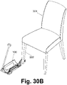
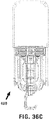
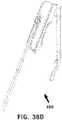
- FIGS. 30A and 30B demonstrate the apparatus 100 having its hook element (or anchor element) partially-surrounding or partially-encircling (or engaging with) a leg 302 of a chair 301.
- Other suitable furniture articles, or other generally-stationary objects, may be used together with the apparatus 100.
- the device may comprise a handle, or an elongated handle or shaft, thereby allowing the user to autonomously operate the device without requiring the user to bend his back or body, or without requiring the user to apply force on its back or its spinal cord or spine; and this may be advantageous to a user who is, for example, sick or ill or disabled or tired.
- the handle or shaft of the device may optionally be (or may comprise), for example, a folding handle, a dis-assembling handle, one or more components able to fold or dis-assemble, or other mechanism allowing the device to have a reduced form-factor in order to facilitate storage of the device and/or transport of the device.
- the device may comprise an axis or hinge or gimbal, or a set of axes or hinges or gimballing elements, which may allow at least two degrees of freedom, or at least several degrees of freedom, or at least two gimballing directions or movement directions, thereby enabling the user to autonomously and easily perform the donning process (e.g., a first gimbal direction which may be generally parallel to the ground surface; and a second gimbal direction which may be slanted upwardly relative to the ground surface).
- a first gimbal direction which may be generally parallel to the ground surface
- a second gimbal direction which may be slanted upwardly relative to the ground surface
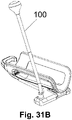
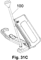
- Figs. 31A , 31B and 31C demonstrate the apparatus 100 in three positions or three states.
- Fig. 31A demonstrates a rest position of apparatus 100; whereas Fig. 31B demonstrates gimballing along a first gimbal direction (e.g., generally parallel to the ground surface); and whereas Fig. 31C demonstrates gimballing along a second, different, gimbal direction (e.g., generally slanted relative to the ground surface).
- the gimballing elements or the gimbals of apparatus 100 may allow simultaneous movement or concurrent movement of the caddy (or other element(s) of apparatus 100) in both of the gimbal directions, at the same time.
- Some embodiments of the present invention may include an apparatus (or device) for donning socks, the apparatus comprising: a substantially horizontal base; an elongated U-shaped, semi-cylindrical caddy on which a sock positioned inside out is fittable and into an interior of which a foot is insertable; and a tilt unit coupled to said caddy and pivotally connected to a head portion of said base.
- the base is T-shaped and is configurable by an elongated main portion and two spaced, forwardly positioned head portions; wherein the tilt unit is insertable within an interspace between said two head portions; wherein the tilt unit is pivotally connected to said two head portions by at least one coupled horizontally disposed pin which is substantially perpendicular to said main portion; wherein the pin is introducible within a recess formed within a forwardly positioned projection of the tilt unit; wherein the tilt unit and the caddy are able to be tilted about a horizontal axis during a sock donning operation.
- the tilt unit has a central through-hole through which a part protruding from the caddy and connected with a projection of a flange passes; wherein said through-hole is positioned rearwardly from the projection of the tilt unit, allowing the caddy and flange to be rotated in unison about a vertical axis during the sock donning operation.
- the flange comprises a flange that limits the rotational displacement of the caddy about a central axis of the through hole.
- an inner face of each of the two head portions has (a) an upper, substantially straight and un-recessed region, and (b) a lower region which is angularly recessed with respect to said upper region, thereby allowing the flange to rotate for a predetermined angular distance when the caddy is at a rest position until the flange contacts said inner face, yet preventing the flange from rotating when the caddy is tilted.
- the apparatus further comprises: a hook member that is engageable with a relatively stationary element for providing a reactive force during the sock donning operation.
- the elongated main portion of the base is hollowed to fixedly receive the hook member.
- the hook member is selectively extendable with respect to the elongated main portion of the base.
- the hook member comprises: an elongated positioning bar formed with a plurality of longitudinally spaced latching grooves; a hook rearwardly extending from said positioning bar; and a spring biased detent pivotally connected to the main portion of the base for selectively engaging one of said grooves.
- the detent comprises: a finger contactable portion for disengaging the detent from the engaged groove, to allow the bar to be repositioned.
- the apparatus further comprises: a pole assembly extending upwardly from one of the head portions, for facilitating manual displacement of the apparatus.
- the pole assembly comprises: a straight pole section, and a bent pole section that is movable within a cup attachment fixed to the base, for facilitating apparatus repositioning.
- a method or process for donning (or putting on, or wearing) a sock may comprise: (a) providing an apparatus comprising a substantially horizontal base and an elongated U-shaped, semi-cylindrical caddy movably coupled to said base; (b) fitting a sock in an inside out arrangement over a rearward terminal edge of said caddy; (c) securing said base to a relatively stationary element for providing a reactive force during a sock donning operation while a user is positioned to the rear of said caddy; (d) inserting a foot of the user into the interior of the sock, while said foot applies a moment to said caddy to cause said caddy to pivot and an open end of the sock is gradually slipped off said rearward terminal edge of said caddy; and (e) fully inserting toes of the user into a toe portion of the sock, to cause said caddy to assume a final pivoted position and the sock to be released from said
- the caddy also rotates about a substantially vertical axis while the foot is being inserted into the interior of the sock.
- a first sock donning apparatus and a second sock donning apparatus are positioned forwardly to right and left feet, respectively, and first and second socks are donned on the right and left feet, respectively, thereby.
- the first and second socks may be donned substantially simultaneously or concurrently or in parallel to each other.
- the method further comprises: providing a hook member coupled to the base; and affixing said hook member to the relatively stationary element.
- the hook member is extendable; wherein the length of the hook member is set prior to inserting the foot into the interior of the sock.
- the method further comprises: utilizing a pole assembly, which extends upwardly from the base, to adjust a direction of the caddy relative to a direction of the foot to be inserted into the interior of the sock.
- the pole assembly comprises: a straight pole section; a hand graspable knob fitted from above to said straight pole section; and a bent pole section fitted from below to said straight pole section that is rotatable within a cup attachment fixed to the base; wherein the method further comprises: selectively rotating said bent pole section when desired to bring said knob closer or farther away from the relatively stationary element in order to facilitate apparatus repositioning.
- the device for wearing or donning socks which is depicted in Figs. 1 to 31C and which is discussed above in relation to Figs. 1 to 31C , may be modified and/or improved and/or enhanced in order to achieve a more-efficient, more user-friendly, more convenient, more useful, and/or more versatile device for wearing or donning or putting-on socks.
- modified or improved device for wearing socks with its improvements, modifications, additions, substitutions, and/or other changes, in accordance with the present invention, is demonstrated in Figs. 32 to 38E , and is further discussed herein; however, such improved device may comprise or may incorporate therein some of the units or modules or features that are depicted in any one of Figs. 1 to 31C and/or that are discussed in the text with reference to any one of Figs. 1 to 31C .
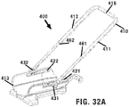
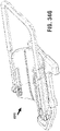
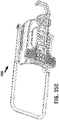
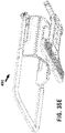
- FIG. 32A to 32E demonstrate an improved device 400 for wearing socks (or for assisting a person in putting-on a sock), and its improved components or units, in accordance with some demonstrative embodiments of the present invention.
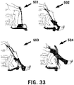
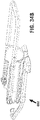
- Fig. 33 demonstrates four stages 501-504 of a process of using the device 400 for wearing or putting-on a sock, in accordance with some demonstrative embodiments of the present invention.
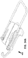
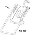
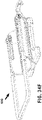
- Figs. 34A to 34H are additional schematic illustrations of the improved device 400 for wearing socks, and its improved components, in accordance with some demonstrative embodiments of the present invention.
- Figs. 35A to 35F are further schematic illustrations of the improved device 400 for wearing socks, and its improved components, in accordance with some demonstrative embodiments of the present invention.
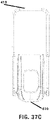
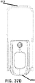
- Figs. 36A to 36G are additional schematic illustrations of the improved device 400 for wearing socks, and its improved components, in accordance with some demonstrative embodiments of the present invention.
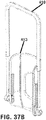
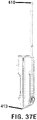
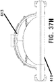
- Figs. 37A to 37H are schematic illustrations of the improved handle assembly and the improved caddy, of the improved device for wearing socks, in accordance with some demonstrative embodiments of the present invention.
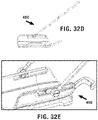
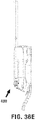
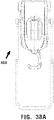
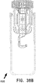
- Figs. 38A to 38E are additional schematic illustrations of the improved device 400 for wearing socks, and its improved components, in accordance with some demonstrative embodiments of the present invention.
- conventional sock-donning devices can be improved and/or modified, in a manner that would make them suitable for donning or for wearing of various types of socks, including, for example, compression socks, pressure socks, stockings, compression stockings, Thrombo-Embolic Deterrent (TED) Hose socks, TED Hose compression socks, or the like, and/or in a manner that would make them more useful for persons that are disabled or handicapped, or for older persons or for persons that suffer from a particular medical condition that makes it more difficult for them to put-on socks.
- TED Thrombo-Embolic Deterrent
- sock-donning devices may not enable a user to don, through such devices, an elongated sock and/or a compression sock and/or a TED Hose sock, due to the length and/or compression and/or elasticity and/or other features of such sock(s).
- the improved sock-wearing device(s) of the present invention may enable the user to don or to put-on such sock(s), efficiently and/or rapidly and/or easily.
- a single pole, or a single handle, or a single shaft, or a single pole assembly 71 may be insufficient or non-optimal for achieving the result of efficient and user-friendly donning of a sock. Accordingly, the Applicants have devised an improved Handle Assembly 410 (or a handle arrangement, or a handle structure), which has improved components, improved mode of operation, improved and more useful location, and other improved features.
- the handle assembly 410 is located centrally to the device, instead of having the side-oriented location of the pole assembly 71.
- the Applicants have realized that a single pole assembly 71, that is located on the side of the device (e.g., entirely on the right side of the device; or entirely on the left side of the device), does not provide sufficient power or force or counter-force or leverage to the user operating the pole assembly, and/or does not provide efficient operation to the device.
- the handle assembly 410 is located on top of, or above relative to, a caddy 413 or tube or semi-tube or foot-insertion component or foot-resting component, in which the user puts or inserts or rests his foot.
- the handle assembly 410 is structured not as a single pole and not as a single shaft, but rather, as a dual-pole or a generally-rectangular component or a "U” shaped component or an Upside-Down U-shaped handle assembly, or as an "n" shaped component or member, which allows the user to apply approximately 1.25 times or 1.50 times or twice (or more) the amount of force that is applied in a single pull, relative to using a single handle or single pole assembly.
- the location of the handle assembly 410 within the device 400 rather than being at a side of the foot, and due to the improved location on top of (or above) the foot and the caddy 413, enables and/or ensures that most or all of the manual force(s) that are applied by the user, indeed translate or are converted directly and immediately into a sock-pulling operation of the device 400, without any loss of force(s) due to the previous side-location of the pole assembly 71.
- the handle assembly 410 comprises, for example, a first pulling rod 411, which is generally perpendicular to a second pulling rod 412; and the two pulling rods 411-412 are connected at their top via a top-side bridge handle 415, which the user grasps or holds or grabs in order to simultaneously apply force (e.g., a pull force) on both of the rods 411-412, thereby allowing the user to utilize a single bridge handle 415 (e.g., pulled or operated by one hand of the user) in order to manipulate and control two generally-parallel pulling rods 411-412 which are located, in turn, on both the right side of his foot and the left side of his foot, and are both operated via the single bridge handle 415 which is located vertically on top of the foot or vertically relative to the foot.
- a single bridge handle 415 e.g., pulled or operated by one hand of the user
- the handle assembly 410 is free to move along or within or relative to a pair of two slider channels 421-422 (e.g., a right-side slider channel, and a left-side slider channel), which are located at or along two opposite sides of the improved caddy 413.
- the handle assembly 410 may terminate with (or may be attached to, or may engage with) a pair of sliding connectors 431-432, each such sliding connector able to keep the handle assembly 410 connected and non-detachable from the improved caddy 413, while also allowing or enabling the handle assembly 410 to move along an additional degree of freedom, namely, enabling it the ability to move or to slide along the slider channels 421-422.
- the improved handle assembly 410 is further capable of sliding or moving along the improved caddy 413, via or within the slider channels 421-422; such that the points-of-connection or the edge-of-connection of the handle assembly 410 and the improved caddy 413 are not static but rather they are able to move or slide as the user operates (e.g., rotates, spins, pulls) the handle assembly 410.
- the two slider channels 421-422 may assist the user in pulling upwardly the sock, during the sock-wearing operation that is performed via (or by utilizing) the device 400.
- the additional degree-of-freedom that allows the handle assembly 410 to move in additional direction(s) and/or to slide horizontally within the slider channels 421-422, may thus assist the user in the entirety of the sock-wearing process, or at least in the later part of the sock-wearing process in which the sock is rolled-up along the leg of the user and/or towards the thigh of the user and/or towards the hip of the user.
- the handle assembly 410 may be structured by using telescopic mechanisms or other shrinkage / expansion mechanism; for example, by using two telescopic mechanisms 461-462 (e.g., a cylinder-within-cylinder mechanism) which allow the rods 411-412 to shrink (or to collapse, or to retrace) and to expand (or to extend, or to increase in length).
- two telescopic mechanisms 461-462 e.g., a cylinder-within-cylinder mechanism
- a ratchet mechanism or multiple ratchets, or position-locking elements or mechanisms, or a pin and hole mechanism, or a male-female mechanism, or other suitable mechanisms may be incorporated into the handle assembly 410 in order to enable the user to selectively define and secure the desired length or size of the hand assembly 410, for example, at a particular length or size, or at pre-defined distance intervals or length intervals or size intervals.
- Such telescopic mechanism(s), or other compression / expansion mechanisms of the handle assembly 410 may provide multiple benefits and advantages; for example, the ability of a single device 400 to accommodate and to serve a tall user and a short user; the ability to lift the device 400 from the floor (e.g., to transport it) without necessarily bending down; the ability to place the device on the ground or on the floor without necessarily bending down; the ability to efficiently use the user's arm muscles and/or hand muscles and/or other muscles (e.g., upper chest) during the operation of the sock-wearing functionality of the device.
- handle assembly 410 and its particular sliding interaction with the improved caddy 413 and the slider channels 421-422, enable the user to easily and efficiently apply additional force(s) to the operation of the handle assembly 410, and/or enable the user to apply an increased amount of force, and/or enable the device to utilize an increased amount of manual force applied by the user, and/or enable the device to accommodate and to serve users having different lengths of arms or hands or fingers or body-parts (e.g., without requiring a tall user to bend-down excessively; or without requiring a short user to extend his arm excessively).
- features and components allow the user of device 400 to apply additional force(s) towards the operation of the sock-wearing function, and to further extend the forces to be applied not only as rotational forces (e.g., as only a single, rotational force was applied to the non-moving and the only-rotating single pole assembly 71), but to also apply horizontal force(s) or other three-dimensional force(s) that are applied to the entire handle assembly 410 as it slides along the improved caddy 413.
- caddy 113 has a main, elongated, surface on which the user mounts his foot, but lacks a suitable opening or structure for an ankle of the foot; and instead, is surrounded on its right-side and on its left-side by curved panels.
- the improved caddy 413 comprises a frame 444, which in turn includes multiple regions: a front-side (or toe-side) frame-region 444F, on which the toes of the user may rest; a right-side frame-region 444R, which supports or holds the right-side of the foot; a left-side frame-region 444L, which supports or holds the left-side of the foot; a back-side (or rear-side, or ankle-side) frame-region 444B, on which, typically, no part of the foot is intended to rest or to touch; and a central, hollow, frame-region 444C which has or comprises a hole or cavity or orifice or aperture, on which (or, in which) the ankle or ankle-area of the foot may rest or may be located.
- a front-side (or toe-side) frame-region 444F on which the toes of the user may rest
- a right-side frame-region 444R which supports or holds the right-side of the foot
- this particular structure of the improved caddy 413 may increase the efficiency and/or the usability of the device 400 and/or the user-convenience when utilizing the device 400.
- the ankle of the user may be relatively free to hover over the hollow central frame-region 444C, and/or to sink downwardly and/or partially into the hollow aperture of the central frame-region 444C; thereby enabling the user to apply a better grip onto the device 400 via the user's ankle, and/or thereby enabling the user to better (or more efficiently) push the device 400 downwardly towards the floor or the ground and thus achieve more-efficient functionality of the device 400, and/or thereby preventing the user from being restricted to having his ankle on a flat surface, and providing increased freedom of movement to the ankle of the foot and/or to the rear-side of the foot during the sock-wearing operation, which in turn translate into more-efficient utilization of the muscles of the foot and to more-efficient sock-wearing functionality.
- the aperture in the improved caddy is structured to accommodate therein at least a portion of the ankle of the user, or at least a portion of a lower-surface or lower-region of the sole (the underside of the foot), in a manner that enables the user to push-down or to squeeze-down the improved caddy, downwardly towards the ground or the floor, thereby contributing or creating an additional force that pins-down the device 400 and/or the stabilizes the device 400 during the sock wearing process and thus enabling a smoother and more-reliable process,
- an improved base-component may contribute to further increasing the efficiency of utilizing the sock-donning device.
- the present invention comprises a stable base member 470 which may operate without the optional hook element 41.
- the improved, stable, base member 470 enables efficient and secure operation of the device 400, without requiring the device to be attached to, or hooked to, a leg of a chair or other furniture or anchor; and without necessarily requiring the now-optional hook element 41, which may be entirely removed or detached, thereby decreasing the weight and/or the size and/or the length and/or the dimensions and/or the form-factor of the device 400, and thereby increasing the ease-of-use of device 400, the ease of storage and transportation there, and thereby also allowing a reduction in costs and in breakable components, and a more efficient operation virtually anywhere without necessarily requiring the user to anchor the device to a leg of a furniture.
- the improved base member 470 may be formed as a T-shaped element, having a front-side member 471 which is perpendicular to a central member 472.
- the length of the central member 472 may be generally similar to, or identical to, the length of the front-side member 471.
- the length of the central member 472 may be in the range of 80 to 99 percent of the length of the front-side member 471.
- the length of the central member 472 may he in the range of 101 to 120 percent relative to the length of the front-side member 471.
- the width of the central member 472 may be generally similar to, or identical to, the width of the front-side member 471.
- the width of the central member 472 may be in the range of 80 to 99 percent of the width of the front-side member 471. In some embodiments, the width of the central member 472, may be in the range of 101 to 120 percent relative to the width of the front-side member 471. Other suitable ratios or values or ranges may be used.
- the structure of the improved base member 470 may be such that it enables secure attachment or secure holding or a secure pinning-down of the entirety of device 400 to a floor or to the ground by pressing-down of a human foot onto the improved caddy 413 and thereby creating a pin-down force of friction that stops the device 400 from moving sideways or back-and-forth relative to the ground or floor.
- a bottom-side of the improved base member 470 may optionally comprise one or more rubber elements 475 or non-slip elements or no-skid elements or friction-creating elements, which may assist in securing the device 400 onto a stable position on the floor or on the ground, while also preventing slipping or sliding or skidding of the device 400 over such floor, and/or while also enabling efficient and easy and rapid removal or lifting of the device 400 from such floor (e.g., avoiding any long-term bonding of the device 400 to such floor).
- the device of the present invention is particularly suitable for assisting a user to put on a medical sock or a sock having medical properties or “compression stockings” or a “pressure sock” or “pressure stocking” or an "elastic sock” or a high-elasticity sock, that is utilized by users that require such sock(s) for medical reasons; for example, due to vein problems, or due to a need to stand many hours per day, or for other conditions or reasons.
- Such “pressure sock” or “compression stocking” may be formed or knitted from one or more elastic fabric(s) and/or elastic material(s) in a manner that enables such sock to apply a high level of force or pressure on the veins and/or capillaries, thereby preventing accumulation of liquid(s) in the feet and/or legs and/or thereby improving the flow of blood therein. Since such "pressure sock” or “compression stocking” or highly-elastic sock has a high level of elasticity and is very tight, it may be difficult for a user to put on the sock around his foot and/or to pull-up the sock towards his upper leg or hip (such sock may reach up, even towards the knee or towards the hip).
- the device of the present invention enables a user to easily and efficiently put-on such tight sock, by utilizing the particular structure and/or shape of the device as well as its particular curved (or semi-tubular) caddy or caddy-frame which has specific holes or craters or cavities that allow portion(s) of the sole and/or the ankle to rest therein and/or to enter therein.
- the mechanical mechanism of the device when operated through the pulling of the handle assembly, causes the putting-on or the donning of the sock, onto the foot or sole, backwardly towards and onto the ankle, and then upwardly from the ankle towards the knee.
- the sliders mechanism and the handle assembly enable to put-up the tight sock all the way upwardly, optionally reaching up to the knee of the user; and from the knee and upward the user may utilize his hands to further put-on the tight sock upwardly towards the hip (if desired or if needed).
- the sock donning operation is performed while the user maintains his back (e.g., the back side of his body) at a straight and/or upright position, without needing to bend down or to curve his back; rather, the user holds the handle assembly for the purpose of moving the device, lifting or carrying the device, operating the donning process via the device, and/or otherwise handling the device.
- the device can be used by a right-handed user, as well as a left-handed user. Additionally, the same (e.g., single) device can be used for putting on a sock on the right foot; as well as for putting on a sock on the left foot; wherein both donning processes (for the right foot, and for the left foot) are generally identical processes.
- the device remains generally static or fixed and non-moving, for example, being pressed-down towards the floor and/or being anchored with an anchoring item (e.g., a chair or a sofa or a furniture item).
- the device need not be used only with elastic socks or medical socks, but rather, may be utilized with regular or conventional socks or with everyday socks or stockings, thereby making it a dual-purpose or multi-purpose device.
- the caddy comprises a cavity or crater or recess which accommodates the ankle or the back-portion of the sole or the back-region of the sole or the bottom-region of at least a part of the sole, thereby preventing the ankle or the foot to slide or to slid or to move (relative to the caddy) during the sock donning process; and/or thereby stabilizing or fixedly-maintaining the foot or the sole static (relative to the caddy) during the sock donning operation; and/or enabling the user to maintain a generally 90 degree angle between the sole of the foot and the leg, or between the foot and the leg, during the sock donning operation; and avoiding creation of a slanting of the leg relative to the foot (or the sole) during the sock donning process; as demonstrated particularly in stage 502.
- the device may comprise or may utilize a dual-axis gimbal or a dual-axis gimbaling mechanism, which enables the caddy to move along two generally-perpendicular axes or vectors or directions: (i) along the Pitch axis, and (ii) along the Yaw axis; and generally, without freedom of movement along the Roll axis.
- the dual-axis gimbal may comprise, or the dual-direction gimbaling mechanism may be implemented by using, one or more suitable components; for example, as shown in Figs.
- the rectilinear tilt unit 62 the two head portions 111 and 112 of base 101, the tubular and annular pin 64, the forwardly positioned projection 67 of tilt unit 62, the two opposed pin holders 119, the central through-hole 61 through which a circular protruding part 118 of caddy 113 located in the vicinity of forward terminal edge 160 passes, the circular projection 86 protruding from flange 83, and/or other units shown in Figs. 6A and/or 6B.
- Figs. 20 , 21 and 22 The freedom of movement of the caddy along the Pitch axis is demonstrated in Figs. 20 , 21 and 22 . It enables the longest dimension of caddy to be generally horizontal (or, generally parallel to the ground) at the beginning of (or prior to) the sock donning process (as shown in Fig. 20 ); and then enabling the longest dimension of the caddy to become diagonal or slanted relative to the ground (as shown in Fig. 21 ); until it becomes generally perpendicular to the ground upon ending of the sock donning process (as shown in Fig. 22 ).
- the freedom of movement of the caddy along the Pitch axis enables the caddy to accompany the natural motion of the foot as the foot moves forward while the device performs the donning of the sock around the user's sole (or foot) and then ankle and then leg (or lower portion of the leg). Absent such freedom of movement of the device along the Pitch axis, the device would not be operable to perform and/or to complete the sock donning process, and the user's foot would remain stuck or fixed horizontally or generally-horizontally within the caddy.
- Fig. 29 The freedom of movement of the caddy along the Yaw axis (e.g., left and right in a circular or curved manner) is demonstrated in Fig. 29 . It is enabled (e.g., only) in the initial part of the sock donning process or at the commencement of the sock donning process, while the caddy is still horizontal or generally-horizontal or generally-parallel to the floor; and it enables the user to comfortably and efficiently place his foot within the caddy, even if the caddy itself is not entirely aligned relative to the foot, such that the user can slightly move or "spin" the caddy (while it remains parallel to the ground) to allow insertion of the foot into the caddy.
- the freedom of movement along the Yaw axis is stopped or prevented or locked or closed or ends.
- the Yaw movement of the caddy enables the user to comfortably and safely insert his foot into the caddy; and absent such Yaw freedom of movement at the initial steps of the process, the foot of the user would not be easily fit into the caddy, or the foot of the user may bump into a leg of a chair or sofa.
- the dual-axis gimbal or gimbaling mechanism is located at the front side of the caddy, and not for example at the center or at the rear of the caddy; in order to enable correct, efficient, and/or ergonomic movement of the caddy together with the user's foot that is located within the caddy (or is approaching the caddy, or is being inserted into the caddy).
- a device for donning a sock comprises: a substantially horizontal base; an elongated U-shaped, semi-cylindrical caddy on which a sock positioned inside out is fittable and into an interior of which a foot is insertable; and a tilt unit coupled to said caddy and pivotally connected to a head portion of said base, wherein the tilt unit comprises a dual-axis gimbaling mechanism.
- the semi-cylindrical caddy comprises two elongated slider channels, that enable a handle assembly of the device to slide back-and-forth within said elongated slider channels.
- the device further includes the handle assembly, which comprises a right-side rod and a generally-parallel left-side rod which are interconnected by a generally-horizontal bridge handle.
- the right-side rod is located in its entirety on a right side of the foot when the foot is inserted into the semi-cylindrical caddy; and/or, the left-side rod is located in its entirety on a left side of the foot when the foot is inserted into the semi-cylindrical caddy.
- the generally-horizontal bridge handle is located above the foot during a sock donning process that is performed via the device.
- the handle assembly engages with the semi-cylindrical caddy by both (i) pivoting upwardly and (ii) sliding backwards.
- the right-side rod of the handle assembly comprises a first telescopic structure that enables the user to selectively extend or reduce a length of the right-side rod; wherein the left-side rod of the handle assembly comprises a telescopic structure that enables the user to selectively extend or reduce a length of the left-side rod; wherein the bridge handle, that interconnects the right-side rod and the left-side rod, is a non-telescopic handle and has a fixed length.
- the semi-cylindrical caddy comprises a hollow frame; wherein a central cavity of said hollow frame accommodates thereon an ankle of the foot; wherein a front-side of said hollow frame accommodates thereon toes of the foot.
- the semi-cylindrical caddy comprises a hollow frame; wherein a central cavity of said hollow frame accommodates thereon an ankle of the foot; wherein a front-side of said hollow frame accommodates thereon toes of the foot; wherein said central cavity, when a sole of the foot is laid therein, enables a friction force between the foot and the semi-cylindrical caddy which prevents the foot from sliding along the semi-cylindrical caddy.
- the semi-cylindrical caddy comprises a hollow frame; wherein a central cavity of said hollow frame accommodates thereon a rear portion of a sole of the foot; wherein a front-side of said hollow frame accommodates thereon toes of the foot; wherein said hollow frame enables the user to pin-down said device towards a floor by applying a downward force at the sole of the foot, and/or enables the user to pin-down his foot or his sole downwardly towards the caddy to avoid slipping or sliding of his foot relative to the caddy.
- the device comprises a base member to enable a user to secure the device onto a floor by pressing-down with the foot downwardly through the semi-cylindrical caddy.
- a bottom-side of the base member comprises a set of rubber members to temporarily and securely stabilize the base member onto the floor without permanently connecting the base member to the floor.
- the device comprises a hook member to anchor the device to an anchoring item (e.g., a furniture leg) which is external to the device and which is separate from the device.
- an anchoring item e.g., a furniture leg
- the device has at least three location-securing mechanisms for fixedly securing a location of the device during a sock donning operation; wherein a first location-securing mechanism is said hook member; wherein a second location-securing mechanism is said set of rubber members under said bottom-side of the base member; wherein a third location-securing mechanism is said hollow frame having said central cavity of said semi-cylindrical caddy.
- a first location-securing mechanism is said hook member
- a second location-securing mechanism is said set of rubber members under said bottom-side of the base member
- a third location-securing mechanism is said hollow frame having said central cavity of said semi-cylindrical caddy.
- at least two of these three location-securing mechanisms, or all three of them, are comprised in the device.
- the dual-axis gimbaling mechanism which is connected to the head portion of the base, (I) is coupled to a front end of the caddy, and (II) enables the caddy to move along a Pitch freedom of movement axis during a sock donning process, and (III) enables the caddy to move along a Yaw freedom of movement axis only at an initial portion of the sock donning process while the caddy is generally parallel to a ground.
- an apparatus for donning socks comprises: a substantially horizontal base; an elongated U-shaped, semi-cylindrical caddy on which a sock positioned inside out is fittable and into an interior of which a foot is insertable; and a tilt unit coupled to said caddy and pivotally connected to a head portion of said base; wherein the semi-cylindrical caddy comprises two elongated slider channels, that enable a handle assembly of the device to slide back-and-forth within said elongated slider channels; wherein the apparatus further comprises said handle assembly, which comprises a right-side rod and a generally-parallel left-side rod which are interconnected by a generally-horizontal bridge handle; wherein the right-side rod is located in its entirety on a right side of the foot when the foot is inserted into the semi-cylindrical caddy; wherein the left-side rod is located in its entirety on a left side of the foot when the foot is inserted into the semi-cylindrical caddy; wherein
Landscapes
- Socks And Pantyhose (AREA)
Claims (14)
- Vorrichtung (100) zum Anziehen von Socken, die Folgendes umfasst:eine im Wesentlichen horizontale Basis (101);eine längliche, U-förmige, halbzylindrische Schale (113), auf die eine Socke mit der Innenseite nach außen gelegt und in die ein Fuß gestellt werden kann;eine Kippeinheit (62), die mit der Schale gekoppelt und schwenkbar mit einem Kopfabschnitt (111, 112) der Basis verbunden ist, wobei die Kippeinheit einen zweiachsigen Kardanmechanismus umfasst; undeine Griffbaugruppe (410), wobei die halbzylindrische Schale zwei längliche Gleitkanäle (421, 422) umfasst und wobei die Griffbaugruppe dazu eingerichtet ist, innerhalb der länglichen Gleitkanäle hin und her zu gleiten.
- Vorrichtung nach Anspruch 1, wobei die Griffbaugruppe eine rechte Stange und eine im Wesentlichen parallele linke Stange umfasst, die durch einen im Wesentlichen horizontalen Brückengriff (415) miteinander verbunden sind.
- Vorrichtung nach Anspruch 2, wobei die rechte Stange zur Gänze auf einer rechten Seite des Fußes angeordnet ist, wenn der Fuß in die halbzylindrische Schale eingesetzt ist;
wobei die linke Stange zur Gänze auf einer linken Seite des Fußes angeordnet ist, wenn der Fuß in die halbzylindrische Schale eingesetzt ist. - Vorrichtung nach Anspruch 2 oder 3, wobei während des Anziehens einer Socke mithilfe der Vorrichtung der im Wesentlichen horizontale Brückengriff oberhalb des Fußes angeordnet ist.
- Vorrichtung nach einem der Ansprüche 1 bis 4, wobei während des Anziehens einer Socke die Griffbaugruppe mit der halbzylindrischen Schale in Eingriff kommt, indem sie (i) nach oben schwenkt und (ii) nach hinten gleitet.
- Vorrichtung nach einem der Ansprüche 2 bis 5, wobei die rechte Stange der Griffbaugruppe eine erste Teleskopstruktur umfasst, mit der der Benutzer die rechte Stange selektiv verlängern oder verkürzen kann;wobei die linke Stange der Griffbaugruppe eine Teleskopstruktur (461, 462) umfasst, mit der der Benutzer die linke Stange selektiv verlängern oder verkürzen kann;wobei der Brückengriff, der die rechte Stange und die linke Stange miteinander verbindet, kein teleskopischer Griff ist und eine feste Länge aufweist.
- Vorrichtung nach einem der Ansprüche 1 bis 6, wobei die halbzylindrische Schale einen hohlen Rahmen (444C) umfasst;wobei ein zentraler Hohlraum des hohlen Rahmens einen Knöchel des Fußes aufnimmt;wobei eine Vorderseite des hohlen Rahmens Zehen des Fußes aufnimmt.
- Vorrichtung nach Anspruch 7,
wobei der zentrale Hohlraum, wenn eine Fußsohle darin liegt, eine Reibungskraft zwischen dem Fuß und der halbzylindrischen Schale ermöglicht, sodass der Fuß nicht an der halbzylindrischen Schale entlanggleitet. - Vorrichtung nach Anspruch 7 oder 8, wobei ein zentraler Hohlraum des hohlen Rahmens einen hinteren Abschnitt einer Fußsohle aufnimmt;
wobei der Benutzer durch den hohlen Rahmen die Vorrichtung auf den Boden drücken kann, indem er an der Fußsohle eine nach unten gerichtete Kraft ausübt. - Vorrichtung nach einem der Ansprüche 1 bis 9, die ein Basiselement umfasst, mit dem der Benutzer die Vorrichtung am Boden befestigen kann, indem er mit dem Fuß durch die halbzylindrische Schale nach unten drückt.
- Vorrichtung nach Anspruch 10, wobei eine Unterseite des Basiselements einen Satz Gummielemente aufweist, die das Basiselement vorübergehend und sicher auf dem Boden stabilisieren, ohne das Basiselement dauerhaft mit dem Boden zu verbinden.
- Vorrichtung nach einem der Ansprüche 1 bis 11, das ferner ein Hakenelement (41) umfasst, um die Vorrichtung an einem Verankerungsgegenstand zu verankern, der außerhalb der Vorrichtung angeordnet und von der Vorrichtung getrennt ist.
- Vorrichtung nach Anspruch 11 und 12, wobei die Vorrichtung wenigstens drei Befestigungsmechanismen zum sicheren Befestigen einer Stelle der Vorrichtung während des Anziehens einer Socke aufweist,wobei ein erster Befestigungsmechanismus das Hakenelement ist,wobei ein zweiter Befestigungsmechanismus der Satz Gummielemente (475) an der Unterseite des Basiselements ist,wobei ein dritter Befestigungsmechanismus der hohle Rahmen ist, der den zentralen Hohlraum der halbzylindrischen Schale aufweist.
- Vorrichtung nach einem der Ansprüche 1 bis 13, wobei der mit dem Kopfabschnitt der Basis verbundene zweiachsige Kardanmechanismus (I) mit einem vorderen Ende der Schale gekoppelt ist und (II) es der Schale ermöglicht, sich entlang einer Kippachse zu bewegen, während eine Socke angezogen wird, und (III) es der Schale ermöglicht, sich, wenn eine Socke angezogen wird, nur anfangs entlang einer Gierachse zu bewegen, während die Schale im Wesentlichen parallel zum Boden ist.
Applications Claiming Priority (2)
| Application Number | Priority Date | Filing Date | Title |
|---|---|---|---|
| US201662399495P | 2016-09-26 | 2016-09-26 | |
| PCT/IL2017/051076 WO2018055628A1 (en) | 2016-09-26 | 2017-09-26 | Device for wearing socks, and method of using such device |
Publications (3)
| Publication Number | Publication Date |
|---|---|
| EP3515263A1 EP3515263A1 (de) | 2019-07-31 |
| EP3515263A4 EP3515263A4 (de) | 2020-06-03 |
| EP3515263B1 true EP3515263B1 (de) | 2022-06-22 |
Family
ID=61689386
Family Applications (1)
| Application Number | Title | Priority Date | Filing Date |
|---|---|---|---|
| EP17852547.3A Not-in-force EP3515263B1 (de) | 2016-09-26 | 2017-09-26 | Vorrichtung zum anziehen von socken |
Country Status (3)
| Country | Link |
|---|---|
| US (1) | US10918233B2 (de) |
| EP (1) | EP3515263B1 (de) |
| WO (1) | WO2018055628A1 (de) |
Families Citing this family (6)
| Publication number | Priority date | Publication date | Assignee | Title |
|---|---|---|---|---|
| CN110051200B (zh) * | 2019-03-14 | 2020-08-28 | 杭州电子科技大学 | 全自动穿袜装置 |
| US11375836B2 (en) * | 2020-10-16 | 2022-07-05 | Vive Health LLC | Device for sock placement over and removal from a foot of a user |
| USD980579S1 (en) | 2020-10-16 | 2023-03-14 | Walker Edison Furniture Company Llc | Sock assist device |
| US11622641B1 (en) * | 2021-12-01 | 2023-04-11 | Edwin J. Stacey | Portable dressing aid device |
| USD1000038S1 (en) | 2022-01-21 | 2023-10-03 | Vive Health LLC | Bendable sock assist |
| CZ37821U1 (cs) * | 2024-03-13 | 2024-04-09 | Jaroslav Kučera | Obouvák ponožek |
Family Cites Families (26)
| Publication number | Priority date | Publication date | Assignee | Title |
|---|---|---|---|---|
| US2828057A (en) | 1956-07-16 | 1958-03-25 | Maclauchlan William | Device for putting on stockings |
| US3231160A (en) * | 1964-09-21 | 1966-01-25 | Mode R Glanville | Sock puller |
| IT1095599B (it) | 1978-05-15 | 1985-08-10 | Marchetti Luigi | Attrezzo manuale per l'indossamento di calze singole da uomo o da donna |
| DE2940038C2 (de) * | 1979-10-03 | 1982-08-19 | Heinz 7260 Calw Rentschler | Vorrichtung für Behinderte zum Anziehen von Strümpfen |
| US5593071A (en) | 1995-01-09 | 1997-01-14 | Lusk; Robert A. | Device for aiding in donning garments |
| US5927573A (en) | 1996-09-16 | 1999-07-27 | Votino; Anthony | Shoe horn for the physically handicapped |
| US5894970A (en) | 1997-04-10 | 1999-04-20 | North Coast Medical, Inc. | Sock or stocking application device and method of use |
| US6102262A (en) | 1999-10-01 | 2000-08-15 | Nicholson; William | Footwear donning assist assembly |
| FR2837688B1 (fr) * | 2002-03-28 | 2005-05-13 | Michel Henri Delamare | Appareil pour mise en place et retrait, sur un membre inferieur, d'une chaussette ou d'un bas de contention elastique |
| US7070074B2 (en) * | 2003-01-30 | 2006-07-04 | Bel-Art Products, Inc. | Hosiery donning aid |
| DE102004001905A1 (de) | 2003-04-25 | 2005-10-27 | Johann Lenhart | Vorrichtung zum An- und Ausziehen eines Strumpfes |
| DE20306424U1 (de) * | 2003-04-25 | 2003-07-24 | Lenhart, Johann, 71384 Weinstadt | Strumpf-Anzieh-Element,Strumpf-Auszieh-Element |
| US6951224B2 (en) | 2003-06-19 | 2005-10-04 | Garrett Melvin C | Walking support having shoehorn/gripper and magnet accessories |
| IL162824A (en) | 2004-07-01 | 2009-12-24 | Reuven Boaron | Apparatus for donning socks |
| US7270253B2 (en) | 2005-05-06 | 2007-09-18 | Ethel Radke | Hosiery remover and method of removing hosiery |
| NL1030634C2 (nl) * | 2005-12-09 | 2007-06-12 | Steven Bernardus Ant Westerbos | Kous-uittrekhulp. |
| AU2006203009B1 (en) | 2006-07-14 | 2007-03-01 | Ezy-As Abc Pty Ltd | A Compression Stocking Applicator |
| US7287675B1 (en) | 2006-10-19 | 2007-10-30 | Sullivan Michael T | Three-in-one health care system |
| US20090120975A1 (en) * | 2007-11-09 | 2009-05-14 | Schoepe Erich G | Sock donning device |
| ITRM20080327A1 (it) | 2008-06-20 | 2009-12-21 | Giuseppe Moscato | Dispositivo per infilare calze calzini calze elastiche e collant |
| IT1396348B1 (it) * | 2009-10-30 | 2012-11-19 | Fantasia | Infilacalze universale |
| US8528796B1 (en) | 2011-06-23 | 2013-09-10 | Richard K. Bosko | Sock donning appliance |
| ITRM20120138A1 (it) * | 2012-04-04 | 2013-10-05 | Giuseppe Moscato | Dispositivo per indossare collant ed indumenti di tipo analogo |
| US8356735B1 (en) * | 2012-06-15 | 2013-01-22 | Drakeford Melvin L | Method and apparatus for putting on and taking off socks or stockings |
| DK177776B1 (da) * | 2013-06-18 | 2014-06-23 | On & Off Aps | Anordning til påføring og aftrækning af strømper samt anvendelse |
| US9119494B2 (en) * | 2013-10-30 | 2015-09-01 | Reuven Boaron | Apparatus for wearing socks |
-
2017
- 2017-09-26 WO PCT/IL2017/051076 patent/WO2018055628A1/en not_active Ceased
- 2017-09-26 US US16/335,255 patent/US10918233B2/en active Active
- 2017-09-26 EP EP17852547.3A patent/EP3515263B1/de not_active Not-in-force
Also Published As
| Publication number | Publication date |
|---|---|
| US10918233B2 (en) | 2021-02-16 |
| EP3515263A1 (de) | 2019-07-31 |
| US20190254458A1 (en) | 2019-08-22 |
| EP3515263A4 (de) | 2020-06-03 |
| WO2018055628A1 (en) | 2018-03-29 |
Similar Documents
| Publication | Publication Date | Title |
|---|---|---|
| EP3515263B1 (de) | Vorrichtung zum anziehen von socken | |
| TWI686189B (zh) | 拐杖 | |
| US11426323B2 (en) | Multi-functional foot crutch | |
| US9386875B2 (en) | Combination shoe horn and sock donning and doffing apparatus | |
| US10532001B2 (en) | Crutch | |
| US20240148597A1 (en) | Crutch | |
| US7364056B2 (en) | Apparatus for wearing socks | |
| JP6836691B2 (ja) | 杖 | |
| US9119494B2 (en) | Apparatus for wearing socks | |
| US10405669B2 (en) | Compact, portable elevating device for a lower limb | |
| US8047216B2 (en) | Standing aid | |
| KR102876900B1 (ko) | 양말 착탈 보조장치 | |
| EP3533362B1 (de) | Hilfsvorrichtung zum an- und ausziehen von kompressionssocken | |
| CN111685974A (zh) | 一种助行器 | |
| CN120267924A (zh) | 一种多功能背包式输液辅助装置 | |
| EP2895035A1 (de) | Hilfe zum an- und ausziehen elastischer strümpfe | |
| AU2007100095A4 (en) | Sock Aid | |
| AU2005225089A1 (en) | Sock and Stocking Aid | |
| TWM414839U (en) | Socks wearing assisting device |
Legal Events
| Date | Code | Title | Description |
|---|---|---|---|
| STAA | Information on the status of an ep patent application or granted ep patent |
Free format text: STATUS: THE INTERNATIONAL PUBLICATION HAS BEEN MADE |
|
| PUAI | Public reference made under article 153(3) epc to a published international application that has entered the european phase |
Free format text: ORIGINAL CODE: 0009012 |
|
| STAA | Information on the status of an ep patent application or granted ep patent |
Free format text: STATUS: REQUEST FOR EXAMINATION WAS MADE |
|
| 17P | Request for examination filed |
Effective date: 20190417 |
|
| AK | Designated contracting states |
Kind code of ref document: A1 Designated state(s): AL AT BE BG CH CY CZ DE DK EE ES FI FR GB GR HR HU IE IS IT LI LT LU LV MC MK MT NL NO PL PT RO RS SE SI SK SM TR |
|
| AX | Request for extension of the european patent |
Extension state: BA ME |
|
| DAV | Request for validation of the european patent (deleted) | ||
| DAX | Request for extension of the european patent (deleted) | ||
| A4 | Supplementary search report drawn up and despatched |
Effective date: 20200506 |
|
| RIC1 | Information provided on ipc code assigned before grant |
Ipc: A47G 25/90 20060101AFI20200428BHEP |
|
| GRAP | Despatch of communication of intention to grant a patent |
Free format text: ORIGINAL CODE: EPIDOSNIGR1 |
|
| STAA | Information on the status of an ep patent application or granted ep patent |
Free format text: STATUS: GRANT OF PATENT IS INTENDED |
|
| INTG | Intention to grant announced |
Effective date: 20220216 |
|
| GRAS | Grant fee paid |
Free format text: ORIGINAL CODE: EPIDOSNIGR3 |
|
| GRAA | (expected) grant |
Free format text: ORIGINAL CODE: 0009210 |
|
| STAA | Information on the status of an ep patent application or granted ep patent |
Free format text: STATUS: THE PATENT HAS BEEN GRANTED |
|
| AK | Designated contracting states |
Kind code of ref document: B1 Designated state(s): AL AT BE BG CH CY CZ DE DK EE ES FI FR GB GR HR HU IE IS IT LI LT LU LV MC MK MT NL NO PL PT RO RS SE SI SK SM TR |
|
| REG | Reference to a national code |
Ref country code: GB Ref legal event code: FG4D |
|
| REG | Reference to a national code |
Ref country code: CH Ref legal event code: EP |
|
| REG | Reference to a national code |
Ref country code: DE Ref legal event code: R096 Ref document number: 602017058840 Country of ref document: DE |
|
| REG | Reference to a national code |
Ref country code: AT Ref legal event code: REF Ref document number: 1499229 Country of ref document: AT Kind code of ref document: T Effective date: 20220715 |
|
| REG | Reference to a national code |
Ref country code: IE Ref legal event code: FG4D |
|
| REG | Reference to a national code |
Ref country code: LT Ref legal event code: MG9D |
|
| REG | Reference to a national code |
Ref country code: NL Ref legal event code: MP Effective date: 20220622 |
|
| PG25 | Lapsed in a contracting state [announced via postgrant information from national office to epo] |
Ref country code: SE Free format text: LAPSE BECAUSE OF FAILURE TO SUBMIT A TRANSLATION OF THE DESCRIPTION OR TO PAY THE FEE WITHIN THE PRESCRIBED TIME-LIMIT Effective date: 20220622 Ref country code: NO Free format text: LAPSE BECAUSE OF FAILURE TO SUBMIT A TRANSLATION OF THE DESCRIPTION OR TO PAY THE FEE WITHIN THE PRESCRIBED TIME-LIMIT Effective date: 20220922 Ref country code: LT Free format text: LAPSE BECAUSE OF FAILURE TO SUBMIT A TRANSLATION OF THE DESCRIPTION OR TO PAY THE FEE WITHIN THE PRESCRIBED TIME-LIMIT Effective date: 20220622 Ref country code: HR Free format text: LAPSE BECAUSE OF FAILURE TO SUBMIT A TRANSLATION OF THE DESCRIPTION OR TO PAY THE FEE WITHIN THE PRESCRIBED TIME-LIMIT Effective date: 20220622 Ref country code: GR Free format text: LAPSE BECAUSE OF FAILURE TO SUBMIT A TRANSLATION OF THE DESCRIPTION OR TO PAY THE FEE WITHIN THE PRESCRIBED TIME-LIMIT Effective date: 20220923 Ref country code: FI Free format text: LAPSE BECAUSE OF FAILURE TO SUBMIT A TRANSLATION OF THE DESCRIPTION OR TO PAY THE FEE WITHIN THE PRESCRIBED TIME-LIMIT Effective date: 20220622 Ref country code: BG Free format text: LAPSE BECAUSE OF FAILURE TO SUBMIT A TRANSLATION OF THE DESCRIPTION OR TO PAY THE FEE WITHIN THE PRESCRIBED TIME-LIMIT Effective date: 20220922 |
|
| REG | Reference to a national code |
Ref country code: AT Ref legal event code: MK05 Ref document number: 1499229 Country of ref document: AT Kind code of ref document: T Effective date: 20220622 |
|
| PG25 | Lapsed in a contracting state [announced via postgrant information from national office to epo] |
Ref country code: RS Free format text: LAPSE BECAUSE OF FAILURE TO SUBMIT A TRANSLATION OF THE DESCRIPTION OR TO PAY THE FEE WITHIN THE PRESCRIBED TIME-LIMIT Effective date: 20220622 Ref country code: LV Free format text: LAPSE BECAUSE OF FAILURE TO SUBMIT A TRANSLATION OF THE DESCRIPTION OR TO PAY THE FEE WITHIN THE PRESCRIBED TIME-LIMIT Effective date: 20220622 |
|
| PG25 | Lapsed in a contracting state [announced via postgrant information from national office to epo] |
Ref country code: NL Free format text: LAPSE BECAUSE OF FAILURE TO SUBMIT A TRANSLATION OF THE DESCRIPTION OR TO PAY THE FEE WITHIN THE PRESCRIBED TIME-LIMIT Effective date: 20220622 |
|
| PG25 | Lapsed in a contracting state [announced via postgrant information from national office to epo] |
Ref country code: SM Free format text: LAPSE BECAUSE OF FAILURE TO SUBMIT A TRANSLATION OF THE DESCRIPTION OR TO PAY THE FEE WITHIN THE PRESCRIBED TIME-LIMIT Effective date: 20220622 Ref country code: SK Free format text: LAPSE BECAUSE OF FAILURE TO SUBMIT A TRANSLATION OF THE DESCRIPTION OR TO PAY THE FEE WITHIN THE PRESCRIBED TIME-LIMIT Effective date: 20220622 Ref country code: RO Free format text: LAPSE BECAUSE OF FAILURE TO SUBMIT A TRANSLATION OF THE DESCRIPTION OR TO PAY THE FEE WITHIN THE PRESCRIBED TIME-LIMIT Effective date: 20220622 Ref country code: PT Free format text: LAPSE BECAUSE OF FAILURE TO SUBMIT A TRANSLATION OF THE DESCRIPTION OR TO PAY THE FEE WITHIN THE PRESCRIBED TIME-LIMIT Effective date: 20221024 Ref country code: ES Free format text: LAPSE BECAUSE OF FAILURE TO SUBMIT A TRANSLATION OF THE DESCRIPTION OR TO PAY THE FEE WITHIN THE PRESCRIBED TIME-LIMIT Effective date: 20220622 Ref country code: EE Free format text: LAPSE BECAUSE OF FAILURE TO SUBMIT A TRANSLATION OF THE DESCRIPTION OR TO PAY THE FEE WITHIN THE PRESCRIBED TIME-LIMIT Effective date: 20220622 Ref country code: CZ Free format text: LAPSE BECAUSE OF FAILURE TO SUBMIT A TRANSLATION OF THE DESCRIPTION OR TO PAY THE FEE WITHIN THE PRESCRIBED TIME-LIMIT Effective date: 20220622 Ref country code: AT Free format text: LAPSE BECAUSE OF FAILURE TO SUBMIT A TRANSLATION OF THE DESCRIPTION OR TO PAY THE FEE WITHIN THE PRESCRIBED TIME-LIMIT Effective date: 20220622 |
|
| PG25 | Lapsed in a contracting state [announced via postgrant information from national office to epo] |
Ref country code: PL Free format text: LAPSE BECAUSE OF FAILURE TO SUBMIT A TRANSLATION OF THE DESCRIPTION OR TO PAY THE FEE WITHIN THE PRESCRIBED TIME-LIMIT Effective date: 20220622 Ref country code: IS Free format text: LAPSE BECAUSE OF FAILURE TO SUBMIT A TRANSLATION OF THE DESCRIPTION OR TO PAY THE FEE WITHIN THE PRESCRIBED TIME-LIMIT Effective date: 20221022 |
|
| REG | Reference to a national code |
Ref country code: DE Ref legal event code: R097 Ref document number: 602017058840 Country of ref document: DE |
|
| PG25 | Lapsed in a contracting state [announced via postgrant information from national office to epo] |
Ref country code: AL Free format text: LAPSE BECAUSE OF FAILURE TO SUBMIT A TRANSLATION OF THE DESCRIPTION OR TO PAY THE FEE WITHIN THE PRESCRIBED TIME-LIMIT Effective date: 20220622 |
|
| REG | Reference to a national code |
Ref country code: DE Ref legal event code: R119 Ref document number: 602017058840 Country of ref document: DE |
|
| PG25 | Lapsed in a contracting state [announced via postgrant information from national office to epo] |
Ref country code: MC Free format text: LAPSE BECAUSE OF FAILURE TO SUBMIT A TRANSLATION OF THE DESCRIPTION OR TO PAY THE FEE WITHIN THE PRESCRIBED TIME-LIMIT Effective date: 20220622 Ref country code: DK Free format text: LAPSE BECAUSE OF FAILURE TO SUBMIT A TRANSLATION OF THE DESCRIPTION OR TO PAY THE FEE WITHIN THE PRESCRIBED TIME-LIMIT Effective date: 20220622 |
|
| PLBE | No opposition filed within time limit |
Free format text: ORIGINAL CODE: 0009261 |
|
| REG | Reference to a national code |
Ref country code: CH Ref legal event code: PL |
|
| STAA | Information on the status of an ep patent application or granted ep patent |
Free format text: STATUS: NO OPPOSITION FILED WITHIN TIME LIMIT |
|
| GBPC | Gb: european patent ceased through non-payment of renewal fee |
Effective date: 20220926 |
|
| REG | Reference to a national code |
Ref country code: BE Ref legal event code: MM Effective date: 20220930 |
|
| 26N | No opposition filed |
Effective date: 20230323 |
|
| PG25 | Lapsed in a contracting state [announced via postgrant information from national office to epo] |
Ref country code: LU Free format text: LAPSE BECAUSE OF NON-PAYMENT OF DUE FEES Effective date: 20220926 |
|
| PG25 | Lapsed in a contracting state [announced via postgrant information from national office to epo] |
Ref country code: LI Free format text: LAPSE BECAUSE OF NON-PAYMENT OF DUE FEES Effective date: 20220930 Ref country code: IE Free format text: LAPSE BECAUSE OF NON-PAYMENT OF DUE FEES Effective date: 20220926 Ref country code: FR Free format text: LAPSE BECAUSE OF NON-PAYMENT OF DUE FEES Effective date: 20220930 Ref country code: DE Free format text: LAPSE BECAUSE OF NON-PAYMENT OF DUE FEES Effective date: 20230401 Ref country code: CH Free format text: LAPSE BECAUSE OF NON-PAYMENT OF DUE FEES Effective date: 20220930 |
|
| PG25 | Lapsed in a contracting state [announced via postgrant information from national office to epo] |
Ref country code: SI Free format text: LAPSE BECAUSE OF FAILURE TO SUBMIT A TRANSLATION OF THE DESCRIPTION OR TO PAY THE FEE WITHIN THE PRESCRIBED TIME-LIMIT Effective date: 20220622 |
|
| PG25 | Lapsed in a contracting state [announced via postgrant information from national office to epo] |
Ref country code: BE Free format text: LAPSE BECAUSE OF NON-PAYMENT OF DUE FEES Effective date: 20220930 |
|
| PG25 | Lapsed in a contracting state [announced via postgrant information from national office to epo] |
Ref country code: GB Free format text: LAPSE BECAUSE OF NON-PAYMENT OF DUE FEES Effective date: 20220926 |
|
| PG25 | Lapsed in a contracting state [announced via postgrant information from national office to epo] |
Ref country code: IT Free format text: LAPSE BECAUSE OF FAILURE TO SUBMIT A TRANSLATION OF THE DESCRIPTION OR TO PAY THE FEE WITHIN THE PRESCRIBED TIME-LIMIT Effective date: 20220622 |
|
| PG25 | Lapsed in a contracting state [announced via postgrant information from national office to epo] |
Ref country code: HU Free format text: LAPSE BECAUSE OF FAILURE TO SUBMIT A TRANSLATION OF THE DESCRIPTION OR TO PAY THE FEE WITHIN THE PRESCRIBED TIME-LIMIT; INVALID AB INITIO Effective date: 20170926 |
|
| PG25 | Lapsed in a contracting state [announced via postgrant information from national office to epo] |
Ref country code: CY Free format text: LAPSE BECAUSE OF FAILURE TO SUBMIT A TRANSLATION OF THE DESCRIPTION OR TO PAY THE FEE WITHIN THE PRESCRIBED TIME-LIMIT Effective date: 20220622 |
|
| PG25 | Lapsed in a contracting state [announced via postgrant information from national office to epo] |
Ref country code: MK Free format text: LAPSE BECAUSE OF FAILURE TO SUBMIT A TRANSLATION OF THE DESCRIPTION OR TO PAY THE FEE WITHIN THE PRESCRIBED TIME-LIMIT Effective date: 20220622 |
|
| PG25 | Lapsed in a contracting state [announced via postgrant information from national office to epo] |
Ref country code: TR Free format text: LAPSE BECAUSE OF FAILURE TO SUBMIT A TRANSLATION OF THE DESCRIPTION OR TO PAY THE FEE WITHIN THE PRESCRIBED TIME-LIMIT Effective date: 20220622 |
|
| PG25 | Lapsed in a contracting state [announced via postgrant information from national office to epo] |
Ref country code: MT Free format text: LAPSE BECAUSE OF FAILURE TO SUBMIT A TRANSLATION OF THE DESCRIPTION OR TO PAY THE FEE WITHIN THE PRESCRIBED TIME-LIMIT Effective date: 20220622 |
|
| PG25 | Lapsed in a contracting state [announced via postgrant information from national office to epo] |
Ref country code: BG Free format text: LAPSE BECAUSE OF FAILURE TO SUBMIT A TRANSLATION OF THE DESCRIPTION OR TO PAY THE FEE WITHIN THE PRESCRIBED TIME-LIMIT Effective date: 20220622 |
|
| PG25 | Lapsed in a contracting state [announced via postgrant information from national office to epo] |
Ref country code: BG Free format text: LAPSE BECAUSE OF FAILURE TO SUBMIT A TRANSLATION OF THE DESCRIPTION OR TO PAY THE FEE WITHIN THE PRESCRIBED TIME-LIMIT Effective date: 20220622 |