EP3532740B1 - Système de rotation comprenant un palier à gaz axial - Google Patents
Système de rotation comprenant un palier à gaz axial Download PDFInfo
- Publication number
- EP3532740B1 EP3532740B1 EP17788265.1A EP17788265A EP3532740B1 EP 3532740 B1 EP3532740 B1 EP 3532740B1 EP 17788265 A EP17788265 A EP 17788265A EP 3532740 B1 EP3532740 B1 EP 3532740B1
- Authority
- EP
- European Patent Office
- Prior art keywords
- bearing
- mpa
- axial
- rotary system
- radially
- Prior art date
- Legal status (The legal status is an assumption and is not a legal conclusion. Google has not performed a legal analysis and makes no representation as to the accuracy of the status listed.)
- Active
Links
- 238000001816 cooling Methods 0.000 claims description 50
- 125000006850 spacer group Chemical group 0.000 claims description 44
- 239000000463 material Substances 0.000 claims description 21
- 230000003313 weakening effect Effects 0.000 claims description 14
- 238000000149 argon plasma sintering Methods 0.000 claims description 4
- 238000005266 casting Methods 0.000 claims description 3
- 230000008878 coupling Effects 0.000 claims description 3
- 238000010168 coupling process Methods 0.000 claims description 3
- 238000005859 coupling reaction Methods 0.000 claims description 3
- 230000000149 penetrating effect Effects 0.000 claims description 3
- 238000003466 welding Methods 0.000 claims description 3
- 238000004026 adhesive bonding Methods 0.000 claims description 2
- 238000002425 crystallisation Methods 0.000 claims description 2
- 230000008025 crystallization Effects 0.000 claims description 2
- 238000003825 pressing Methods 0.000 claims description 2
- 238000005476 soldering Methods 0.000 claims description 2
- 238000003860 storage Methods 0.000 description 9
- 239000002184 metal Substances 0.000 description 4
- 229910052751 metal Inorganic materials 0.000 description 4
- 238000004519 manufacturing process Methods 0.000 description 3
- 150000002739 metals Chemical class 0.000 description 3
- 239000002826 coolant Substances 0.000 description 2
- 238000006073 displacement reaction Methods 0.000 description 2
- 238000009826 distribution Methods 0.000 description 2
- 239000000203 mixture Substances 0.000 description 2
- 238000007789 sealing Methods 0.000 description 2
- 238000000137 annealing Methods 0.000 description 1
- 230000000712 assembly Effects 0.000 description 1
- 238000000429 assembly Methods 0.000 description 1
- 230000006378 damage Effects 0.000 description 1
- 230000001419 dependent effect Effects 0.000 description 1
- 230000000694 effects Effects 0.000 description 1
- 238000005187 foaming Methods 0.000 description 1
- 239000011888 foil Substances 0.000 description 1
- 210000003734 kidney Anatomy 0.000 description 1
- XLYOFNOQVPJJNP-UHFFFAOYSA-N water Substances O XLYOFNOQVPJJNP-UHFFFAOYSA-N 0.000 description 1
Images


Classifications
-
- F—MECHANICAL ENGINEERING; LIGHTING; HEATING; WEAPONS; BLASTING
- F16—ENGINEERING ELEMENTS AND UNITS; GENERAL MEASURES FOR PRODUCING AND MAINTAINING EFFECTIVE FUNCTIONING OF MACHINES OR INSTALLATIONS; THERMAL INSULATION IN GENERAL
- F16C—SHAFTS; FLEXIBLE SHAFTS; ELEMENTS OR CRANKSHAFT MECHANISMS; ROTARY BODIES OTHER THAN GEARING ELEMENTS; BEARINGS
- F16C33/00—Parts of bearings; Special methods for making bearings or parts thereof
- F16C33/02—Parts of sliding-contact bearings
- F16C33/04—Brasses; Bushes; Linings
- F16C33/06—Sliding surface mainly made of metal
- F16C33/10—Construction relative to lubrication
- F16C33/1005—Construction relative to lubrication with gas, e.g. air, as lubricant
-
- F—MECHANICAL ENGINEERING; LIGHTING; HEATING; WEAPONS; BLASTING
- F16—ENGINEERING ELEMENTS AND UNITS; GENERAL MEASURES FOR PRODUCING AND MAINTAINING EFFECTIVE FUNCTIONING OF MACHINES OR INSTALLATIONS; THERMAL INSULATION IN GENERAL
- F16C—SHAFTS; FLEXIBLE SHAFTS; ELEMENTS OR CRANKSHAFT MECHANISMS; ROTARY BODIES OTHER THAN GEARING ELEMENTS; BEARINGS
- F16C17/00—Sliding-contact bearings for exclusively rotary movement
- F16C17/04—Sliding-contact bearings for exclusively rotary movement for axial load only
-
- F—MECHANICAL ENGINEERING; LIGHTING; HEATING; WEAPONS; BLASTING
- F16—ENGINEERING ELEMENTS AND UNITS; GENERAL MEASURES FOR PRODUCING AND MAINTAINING EFFECTIVE FUNCTIONING OF MACHINES OR INSTALLATIONS; THERMAL INSULATION IN GENERAL
- F16C—SHAFTS; FLEXIBLE SHAFTS; ELEMENTS OR CRANKSHAFT MECHANISMS; ROTARY BODIES OTHER THAN GEARING ELEMENTS; BEARINGS
- F16C35/00—Rigid support of bearing units; Housings, e.g. caps, covers
- F16C35/02—Rigid support of bearing units; Housings, e.g. caps, covers in the case of sliding-contact bearings
-
- F—MECHANICAL ENGINEERING; LIGHTING; HEATING; WEAPONS; BLASTING
- F16—ENGINEERING ELEMENTS AND UNITS; GENERAL MEASURES FOR PRODUCING AND MAINTAINING EFFECTIVE FUNCTIONING OF MACHINES OR INSTALLATIONS; THERMAL INSULATION IN GENERAL
- F16C—SHAFTS; FLEXIBLE SHAFTS; ELEMENTS OR CRANKSHAFT MECHANISMS; ROTARY BODIES OTHER THAN GEARING ELEMENTS; BEARINGS
- F16C37/00—Cooling of bearings
- F16C37/002—Cooling of bearings of fluid bearings
-
- F—MECHANICAL ENGINEERING; LIGHTING; HEATING; WEAPONS; BLASTING
- F16—ENGINEERING ELEMENTS AND UNITS; GENERAL MEASURES FOR PRODUCING AND MAINTAINING EFFECTIVE FUNCTIONING OF MACHINES OR INSTALLATIONS; THERMAL INSULATION IN GENERAL
- F16C—SHAFTS; FLEXIBLE SHAFTS; ELEMENTS OR CRANKSHAFT MECHANISMS; ROTARY BODIES OTHER THAN GEARING ELEMENTS; BEARINGS
- F16C2360/00—Engines or pumps
- F16C2360/23—Gas turbine engines
-
- F—MECHANICAL ENGINEERING; LIGHTING; HEATING; WEAPONS; BLASTING
- F16—ENGINEERING ELEMENTS AND UNITS; GENERAL MEASURES FOR PRODUCING AND MAINTAINING EFFECTIVE FUNCTIONING OF MACHINES OR INSTALLATIONS; THERMAL INSULATION IN GENERAL
- F16C—SHAFTS; FLEXIBLE SHAFTS; ELEMENTS OR CRANKSHAFT MECHANISMS; ROTARY BODIES OTHER THAN GEARING ELEMENTS; BEARINGS
- F16C27/00—Elastic or yielding bearings or bearing supports, for exclusively rotary movement
- F16C27/02—Sliding-contact bearings
-
- F—MECHANICAL ENGINEERING; LIGHTING; HEATING; WEAPONS; BLASTING
- F16—ENGINEERING ELEMENTS AND UNITS; GENERAL MEASURES FOR PRODUCING AND MAINTAINING EFFECTIVE FUNCTIONING OF MACHINES OR INSTALLATIONS; THERMAL INSULATION IN GENERAL
- F16C—SHAFTS; FLEXIBLE SHAFTS; ELEMENTS OR CRANKSHAFT MECHANISMS; ROTARY BODIES OTHER THAN GEARING ELEMENTS; BEARINGS
- F16C32/00—Bearings not otherwise provided for
- F16C32/06—Bearings not otherwise provided for with moving member supported by a fluid cushion formed, at least to a large extent, otherwise than by movement of the shaft, e.g. hydrostatic air-cushion bearings
- F16C32/0603—Bearings not otherwise provided for with moving member supported by a fluid cushion formed, at least to a large extent, otherwise than by movement of the shaft, e.g. hydrostatic air-cushion bearings supported by a gas cushion, e.g. an air cushion
-
- F—MECHANICAL ENGINEERING; LIGHTING; HEATING; WEAPONS; BLASTING
- F16—ENGINEERING ELEMENTS AND UNITS; GENERAL MEASURES FOR PRODUCING AND MAINTAINING EFFECTIVE FUNCTIONING OF MACHINES OR INSTALLATIONS; THERMAL INSULATION IN GENERAL
- F16C—SHAFTS; FLEXIBLE SHAFTS; ELEMENTS OR CRANKSHAFT MECHANISMS; ROTARY BODIES OTHER THAN GEARING ELEMENTS; BEARINGS
- F16C32/00—Bearings not otherwise provided for
- F16C32/06—Bearings not otherwise provided for with moving member supported by a fluid cushion formed, at least to a large extent, otherwise than by movement of the shaft, e.g. hydrostatic air-cushion bearings
- F16C32/0681—Construction or mounting aspects of hydrostatic bearings, for exclusively rotary movement, related to the direction of load
- F16C32/0692—Construction or mounting aspects of hydrostatic bearings, for exclusively rotary movement, related to the direction of load for axial load only
Definitions
- the present invention relates to a rotation system with at least one axial gas bearing.
- Rotation systems with an axial gas bearing contain a housing, a shaft that is rotatable relative to the housing, at least one bearing disk attached to the shaft, and at least one bearing assembly that supports the bearing disk relative to the housing through an axial gas bearing.
- the bearing assembly contains at least one thrust bearing element, which in many designs is formed by two thrust bearing washers, between which the bearing washer is mounted. An air gap is formed between the bearing washer and the axial bearing washers, which ensures gas storage.
- the DE 10 2007 062 496 A1 showing the features of the preamble of claim 1 discloses, among other things, bearing assemblies used in connection with gas turbine engines.
- the bearing assembly includes a pair of lamellar thrust bearings and a pair of spring means which are arranged substantially coaxially on the pair of lamellar thrust bearings. In this way, the bearing is sprung in the axial direction.
- the air gaps here are dependent on the gas pressure, which is disadvantageous.
- these bearing arrangements each contain a large number of independent components, all of which are subject to tolerances that add up.
- the air gap formed between the bearing assembly and the bearing disc should therefore remain as constant as possible, that is to say as independent of these conditions as possible, even under these conditions.
- the bearing surfaces of the axial bearing disks should remain as parallel as possible to one another.
- the rotation system contains a housing, a shaft rotatable relative to the housing, at least one, for example flat bearing disk attached to the shaft, and at least one bearing assembly which supports the bearing disk relative to the housing by means of an axial gas bearing.
- An air gap is thus formed between the bearing assembly, in particular the axial bearing disks described below, and the bearing disk.
- the bearing plate can be flat; alternatively, however, it can also be, for example, conical or have a free geometry, provided that opposite bearing surfaces allow a defined air gap.
- the bearing assembly has a radially inner region, a radially central region, and a radially outer region held by the housing, from the inside to the outside, which supports the bearing disk.
- the radially inner region contains at least one axial bearing element and at least one holding element, the bearing disk being mounted by means of the axial bearing element and the holding element holding the axial bearing element in the axial direction.
- the air gap formed between the bearing assembly and the bearing disc can remain very constant, i.e. practically independent of them, even at high rotational speeds and / or high temperatures and / or high temperature differences and / or other particularly variable operating influences, such as variable gas pressures or centrifugal forces Operating influences.
- variable gas pressures or centrifugal forces Operating influences This is because, in particular, housing deformations that occur can be minimized depending on operating influences so that the desired air gap is deformed at most in a very small permissible range.
- the rotation system can therefore also be operated under these conditions without the risk of excessive deformation of the air gap.
- the radially central region of the bearing assembly can be made more elastic than its radially inner region. This allows the part of the bearing assembly, which supports the bearing washer, overall rather rigid, so that, for example, the axial bearing washers of the bearing assembly remain comparatively parallel to one another even when the housing is warped. Due to its relatively more elastic design, the radially central region as a whole allows a certain elasticity of the radially inner region in relation to the warping housing. The radially central region can be made more elastic than the radially inner region, in particular due to at least one material weakening of the radially central region.
- the radially central region of the bearing assembly can be made more elastic than its radially outer region.
- the bearing assembly can be firmly and / or precisely connected to the housing.
- the radially central region can be made more elastic than the radially outer region, in particular due to at least one material weakening of the radially central region.
- Such a weakening of the material and an elastic design of the central region further contribute to the fact that the air gap formed between the bearing assembly and the bearing disc even at high rotational speeds and / or high temperatures and / or high temperature differences and / or further in particular variable operating influences, such as, for example, variable gas pressures or Centrifugal forces remains very constant and consequently the rotation system can also be operated under these conditions without the risk of excessive deformation of the air gap.
- At least one of the material weakenings can be formed by a recess formed in the axial direction or by an opening penetrating the bearing assembly.
- the recess of the opening can be formed in a spacer, explained in more detail below, in particular in an inner section such a spacer.
- the depression can be formed, for example, by a laser-sintered structure, a bore, an axial recess, a laser structure, a casting rib and / or a milled kidney.
- the weakening of the material can be achieved by a combination of different materials and / or a combination of the same materials with different properties. Different metals can be combined to form a bimetal. A material weakening can also be achieved by a mixture of two or more materials, in particular two or more metals. In principle, the same materials with different properties can be obtained, for example, by different types of production and / or processing, for example by soft annealing, foaming and / or laser sintering.
- the holding element holds the axial bearing element by clamping, screwing, soldering, welding, shrinking, pressing, gluing, crystallization connection, press connection, plastic casting and / or laser sintering.
- the at least one axial bearing element can contain or be formed by two axial bearing disks, between which the bearing disk is mounted.
- the at least one holding element can contain or be formed by two clamping rings which clamp the axial bearing disks in the axial direction. Such trapping does not impermissibly influence the basic geometry of the thrust bearing washers and / or prevent impermissible displacements. Due to the clamping, small displacements in the radial direction are possible without influencing the air gap inadmissibly.
- the holding element preferably contains two clamping blocks, each of which has one of the clamping rings in a radially inner region.
- the terminal blocks can each be formed in one piece.
- the radially central region of the bearing assembly is preferably formed by an inner section of a spacer disk to which the radially inner region of the bearing assembly is attached.
- a spacer enables simple and / or precise adjustment of the air gap.
- the spacer may contain or consist of at least one metal and / or at least one plastic.
- clamping rings described above or the clamping blocks having the clamping rings can be fastened to the inner section of the spacer disk.
- the clamping rings or the clamping blocks having the clamping rings preferably extend in opposite axial directions away from the inner section of the spacer disk.
- the radially outer region of the bearing assembly is formed by an outer section of the spacer disk which is held on the housing. In combination with the spacer and the housing, this results in greater stability, but in particular also an exact connection.
- the inner section of the spacer disk extends as far as between two axial bearing disks to the radially inner region of the bearing assembly.
- the axial bearing disks can then be clamped in the axial direction against the inner section of the spacer disk, so that each of the two axial bearing disks are clamped in the axial direction between the inner section of the spacer disk and one of the clamping blocks.
- the radially central region, in particular the spacer advantageously has a modulus of elasticity in the range from 1,000 MPa to 700,000 MPa, preferably from 3,000 MPa to 400,000 MPa, particularly preferably from 60,000 MPa to 220,000 MPa.
- the radially inner region, in particular the clamping rings advantageously have a modulus of elasticity in the range from 1,000 MPa to 700,000 MPa, preferably from 3,000 MPa to 400,000 MPa, particularly preferably from 60,000 MPa to 220,000 MPa.
- the radially inner region, in particular the axial bearing washers advantageously have a modulus of elasticity in the range from 10,000 MPa to 900,000 MPa, preferably from 100,000 MPa to 700,000 MPa, particularly preferably from 200,000 MPa to 650,000 MPa.
- the bearing assembly particularly preferably has at least one cooling channel extending in the circumferential direction.
- a cooling channel can be formed, for example, inside the bearing disk attached to the shaft or outside, in particular radially outside, this bearing disk. With the help of such a cooling channel, the temperature distribution within the rotation system can be adjusted. This can make a further contribution to the air gap maintaining a geometry that is as defined as possible.
- the cooling channel can be defined, for example, by a groove which is formed in a radially outer region of the clamping blocks mentioned above and which is closed in the axial direction away from the bearing disk by an annular cover.
- the cooling channel can be formed in the bearing disk attached to the shaft, in an axial bearing element, in particular an axial bearing disk, in the spacer disk or in the housing.
- cooling can be formed, for example, by a radial groove on the terminal blocks in the outer region and can be sealed off from the housing by means of sealing elements, for example O-rings.
- the cooling duct extending in the circumferential direction can be connected to a radial cooling duct in the bearing assembly, in particular in the spacer disk. Furthermore, the radial cooling duct in the bearing assembly can be connected to an axial cooling duct in the housing. In this way, the bearing arrangement can be cooled particularly effectively.
- At least one surface enlargement structure can be present in the cooling channel. This is understood to mean a structure which provides for an enlargement of the surfaces delimiting the cooling channel. In this way, an even further improved heat transfer and thus cooling can be achieved.
- the surface enlargement structure can contain, for example, one or more cooling fins, which can be approximately collar-shaped.
- an axial bearing washer can also be formed in one piece with a clamping block, which simplifies manufacture and reduces tolerances.
- the rotation system can be an in particular electrically driven turbomachine, such as a compressor, in particular a turbocompressor, a motor or a generator, a turbine, in particular a turbogenerator, a turbocharger, a clutch system (in particular a magnetic coupling) or a flywheel, especially a kinetic memory.
- a compressor in particular a turbocompressor, a motor or a generator
- a turbine in particular a turbogenerator, a turbocharger
- a clutch system in particular a magnetic coupling
- flywheel especially a kinetic memory
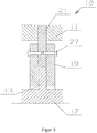
- Rotation system 10 is designed as a turbocompressor. It contains a housing 11 and a shaft 12 which is rotatable relative to the housing 11. A bearing disk 13 which is flat in this exemplary embodiment is fastened to the shaft 12. A Bearing assembly 14 supports the bearing plate 13 relative to the housing 11 by means of an axial gas bearing.
- the bearing assembly 14 has, from the inside to the outside, a radially inner region 15 which supports the bearing disk 13, a radially central region 16 and a radially outer region 17 held by the housing 11. More precisely, it contains a spacer 21 with an inner section 22 and an outer section 23. The outer section 23 of the spacer 21 forms the radially outer region 17 of the bearing assembly 14, which is held on the housing 11. The inner section 22 of the spacer disk 21 forms a radially central region 16 of the bearing assembly 14.
- the inner section 22 of the spacer disk 21 extends between two axial bearing disks 19, which form axial bearing elements 19.
- the bearing disk 13 is mounted between the axial bearing disks 19, wherein air gaps (not shown here) formed between the axial bearing disks 19 and the bearing disk 13 ensure axial gas storage.
- two clamping blocks 26 are fastened with the aid of clamping screws 27, which extend in opposite axial directions from the inner portion 22 of the spacer 21 and only one of which can be seen here.
- the clamping screws 27 penetrate each of the two clamping blocks 26 and the spacer 21, and their screw heads are received in blind holes in the clamping block 26 shown on the right.
- the clamping blocks 26 each have a holding element in the radially inner region, which is designed as a clamping ring 20.
- the clamping rings 20 clamp the axial bearing disks 19 in the axial direction against the inner section 22 of the spacer disk 21, so that each of the two axial bearing disks 19 in the axial direction between the inner section 22 of the spacer disk 21 and one of the two clamping rings 20 are trapped.
- the clamping block 26 and the axial bearing disks 19 together form a radially inner region 15 of the bearing assembly 14.
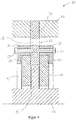
- the inner section 22 of the spacer disk 21 (that is to say the radially central region 16 of the bearing assembly 14) contains a plurality of openings 18 penetrating it in the axial direction.
- the openings 18 form material weaknesses which ensure that the radially central region 16 of the bearing assembly 14 is designed to be more elastic than the radially inner region 15 (ie as the clamping blocks 26 and the axial bearing disks 19).
- the part of the bearing assembly 14 which supports the bearing disk 13 is rather rigid overall, so that the axial bearing disks 19 remain comparatively parallel to one another even when the housing 11 is warped.
- the radially central region 16 Due to its relatively more elastic design, the radially central region 16 as a whole permits a certain elasticity of the radially inner region 15 with respect to the warping housing 11. Alternatively or in addition to the openings 18, depressions can also be provided, which can also form material weakenings with the effects mentioned. Because of the openings 18 mentioned, the radially central region 16 is also more elastic than the radially outer region 17.
- the spacer 21 has a modulus of elasticity of preferably 60,000 MPa to 220,000 MPa.
- the axial bearing disks 19 preferably have an elastic modulus of 200,000 MPa to 650,000 MPa.
- the clamping rings 20 have a preferred elastic modulus of 60,000 MPa to 220,000 MPa.
- This rotation system 10 ensures a high degree of parallelism between the bearing disk 13 and the axial bearing disks 19 even at high rotation speeds and temperatures.
- the temperature distribution can be influenced in a targeted manner with the aid of the cooling channels 24.
- the clamping blocks 26 are structurally separated from the spacer disk 21, so that the components can each be simpler in shape and the production is therefore generally cheaper.
- each of the two clamping blocks 26 is clamped with the spacer 21 in the axial direction with respective clamping screws 27.
- the screw heads of the clamping screws 27 are not received in blind holes here.
- the axial bearing washers 19 are integrally formed with the clamping block.
- only one of the two axial bearing disks 19 can also be formed in one piece with a clamping block.
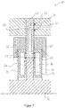
- the rotation system 10 according to Figure 4 differs from that in Figure 2 shown in that the inner portion 22 of the spacer 21 is penetrated by a plurality of openings 18 extending in the axial direction.
- the material weakening is not realized by an opening that completely penetrates the spacer disk 21, but by axial recesses 18 on both sides, which represent depressions 18 formed in the axial direction.
- the depressions 18 can also be arranged only on one side and / or asymmetrically.
- the material weakening 18 is formed by a bimetal or a mixture of two or more materials, in particular two or more metals, in the inner section 22 of the spacer disk 21.
- the stiffness of the spacer 21 can also be adjusted in this way.
- the axial bearing disks 19 each contain a cooling channel 24 which extends in the circumferential direction and which are connected to an axial cooling channel 30 of the housing 11 via radial cooling channels 29 of the spacer disk 21.
- a cooling medium such as water
- O-rings 31 are provided, which serve for an elastic seal.
- Figure 8 shows a further embodiment in which the bearing disk 13 has a cooling channel 24 which extends in the circumferential direction and which can be supplied with a cooling medium by the shaft 12 (not shown).
- the spacer 21 can also have a cooling channel 24, for example, running in the circumferential direction - both radially inside and radially outside the clamping screws 27.
- the cooling channels 24 running radially inside the clamping screws 27 are enclosed by two parts of the spacer 21, which are connected via O-rings 31 in the axial direction.
- the two cooling channels 24 are in accordance with the sectional view Figure 9 not recognizable radial cooling channels connected.
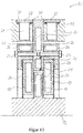
- clamping blocks 26 are provided radially outside of the clamping screws 27 with cooling channels 24 running in the circumferential direction.
- FIG 11 it is the housing 11 which is provided, for example, with cooling channels 24 running in the circumferential direction. These cooling channels 24 are arranged on both sides of the spacer 21 in the axial direction and are closed in the radial direction on the outside by covers 28 which are sealingly fitted with O-rings 31.
- the cooling channels 24 can alternatively also be introduced directly into the housing 11 without a cover, for example by laser sintering or by laser welding.
- the exemplary embodiment shown contains cooling channels 24 which run in the circumferential direction and which are arranged on both sides of the spacer disk 21 and are formed between the clamping blocks 26 and the housing 11. O-rings 31 are provided for elastic sealing between terminal blocks 26 and housing 11.
- Circumferential cooling fins 32 are formed on the radial outside of the clamping blocks 26 and extend into the cooling channels 24.
- the cooling fins 32 enlarge the surface in the cooling channels 24 and thus contribute to better heat transfer and better cooling of the axial bearing.
Claims (16)
- Système de rotation (10) muni d'au moins un palier à gaz axial, ledit système comprenant :- un boîtier (11),- un arbre (12) rotatif par rapport au boîtier (11),- au moins un disque de palier (13) fixé à l'arbre (12),- au moins un ensemble formant palier (14) qui supporte le disque de palier (13) par rapport au boîtier (11) par le biais d'un palier à gaz axial,caractérisé en ce que
l'ensemble formant palier (14) comporte, de l'intérieur vers l'extérieur, une région radialement intérieure (15) supportant le disque de palier (13), une région radialement centrale (16) et une région radialement extérieure (17) maintenue par le boîtier (11), la région radialement intérieure (15) comprenant au moins un élément de palier axial (19) et au moins un élément de retenue (20), le disque de palier (13) étant supporté au moyen de l'élément de palier axial (19) et l'élément de retenue (20) maintenant l'élément de palier axial (19) dans la direction axiale. - Système de rotation (10) selon la revendication 1,
caractérisé en ce que
la région radialement centrale (16) est conçue pour être plus élastique que la région radialement intérieure (15), notamment en raison d'au moins une réduction de matière (18) de la région radialement centrale (16). - Système de rotation (10) selon l'une des revendications précédentes,
caractérisé en ce que
la région radialement centrale (16) est conçue pour être plus élastique que la région radialement extérieure (17), notamment en raison d'au moins une réduction de matière (18) de la région radialement centrale (16). - Système de rotation (10) selon l'une des revendications 2 et 3,
caractérisé en ce que
l'une au moins des réductions de matière (18) est formée par un évidement (18) ménagé dans la direction axiale ou par une couverture (18) ménagée à travers l'ensemble formant palier (14). - Système de rotation (10) selon l'une des revendications précédentes,
caractérisé en ce que
l'élément de retenue (20) maintient l'élément de palier axial (19) par serrage, vissage, brasage, soudage, rétrécissement, pressage, collage, liaison par cristallisation, liaison par pression, moulage de matière synthétique et/ou frittage laser. - Système de rotation (10) selon la revendication 5,
caractérisé en ce que
l'au moins un élément de palier axial (19) comprend, ou est formé par, deux disques de palier axial (19) et l'au moins un élément de retenue (20) comprend, ou est formé par, deux bagues de serrage (20), le disque de palier (13) étant monté entre les disques de palier axial (19) et les bagues de serrage (20) serrant les disques de palier axial (19) dans la direction axiale. - Système de rotation (10) selon l'une des revendications précédentes,
caractérisé en ce que
la région radialement centrale (16) de l'ensemble formant palier (14) est formée par une portion intérieure (22) d'un disque d'espacement (21) à laquelle est fixée la région radialement intérieure (15) de l'ensemble formant palier (14), en particulier les bagues de serrage (20). - Système de rotation (10) selon la revendication 7,
caractérisé en ce que
la région radialement extérieure (17) de l'ensemble formant palier (14) est formée par une portion extérieure (23) du disque d'espacement (21) qui est maintenue au niveau du boîtier (11). - Système de rotation (10) selon l'une des revendications 7 et 8,
caractérisé en ce que
la portion intérieure (22) du disque d'espacement (21) s'étend jusqu'entre deux disques de palier axial (19) de la région radialement intérieure (15) de l'ensemble formant palier (14), entre lesquels le disque de palier (13) est monté. - Système de rotation (10) selon l'une des revendications précédentes,
caractérisé en ce que
la région radialement centrale (16), en particulier le disque d'espacement (21), a un module d'élasticité dans la gamme allant de 1 000 MPa à 700 000 MPa, de préférence de 3 000 MPa à 400 000 MPa, de manière particulièrement préférée de 60 000 MPa à 220 000 MPa. - Système de rotation (10) selon l'une des revendications précédentes,
caractérisé en ce que
la région radialement intérieure (15), en particulier les bagues de serrage (20), a un module d'élasticité dans la gamme allant de 1 000 MPa à 700 000 MPa, de préférence de 3 000 MPa à 400 000 MPa, de manière particulièrement préférée de 60 000 MPa à 220 000 MPa. - Système de rotation (10) selon l'une des revendications 1 à 10,
caractérisé en ce que
la région radialement intérieure (15), en particulier les disques de palier axial (19) et/ou les bagues de serrage (20), a un module d'élasticité dans la gamme allant de 10 000 MPa à 900 000 MPa, de préférence de 100 000 MPa et 700 000 MPa, de manière particulièrement préférée de 200 000 MPa à 650 000 MPa. - Système de rotation (10) selon l'une des revendications précédentes,
caractérisé en ce que
l'ensemble de palier (14) comporte au moins un canal de refroidissement (24) s'étendant dans la direction circonférentielle. - Système de rotation (10) selon la revendication 13,
caractérisé en ce que
le canal de refroidissement (24) s'étendant dans la direction circonférentielle est relié à un canal de refroidissement radial (29) ménagé dans l'ensemble formant palier (14).' - Système de rotation (10) selon la revendication 14,
caractérisé en ce que
le canal de refroidissement radial (29) ménagé dans l'ensemble formant palier (14) est relié à un canal de refroidissement axial (30) ménagé dans le boîtier (11). - Système de rotation (10) selon l'une des revendications précédentes,
caractérisé en ce que
le système de rotation (10) est une machine à fluide (10), en particulier à entraînement électrique, comme par exemple un compresseur, notamment un turbocompresseur, un moteur ou un générateur, une turbine, notamment un turbogénérateur ou un turbocompresseur à suralimentation, un système d'embrayage (en particulier un embrayage magnétique) ou un volant, en particulier un accumulateur cinétique.
Applications Claiming Priority (2)
| Application Number | Priority Date | Filing Date | Title |
|---|---|---|---|
| EP16196569.4A EP3315802A1 (fr) | 2016-10-31 | 2016-10-31 | Système de rotation comprenant un palier à gaz axial |
| PCT/EP2017/077725 WO2018078150A1 (fr) | 2016-10-31 | 2017-10-30 | Système de rotation à palier à gaz axial |
Publications (2)
| Publication Number | Publication Date |
|---|---|
| EP3532740A1 EP3532740A1 (fr) | 2019-09-04 |
| EP3532740B1 true EP3532740B1 (fr) | 2020-08-05 |
Family
ID=57218775
Family Applications (2)
| Application Number | Title | Priority Date | Filing Date |
|---|---|---|---|
| EP16196569.4A Withdrawn EP3315802A1 (fr) | 2016-10-31 | 2016-10-31 | Système de rotation comprenant un palier à gaz axial |
| EP17788265.1A Active EP3532740B1 (fr) | 2016-10-31 | 2017-10-30 | Système de rotation comprenant un palier à gaz axial |
Family Applications Before (1)
| Application Number | Title | Priority Date | Filing Date |
|---|---|---|---|
| EP16196569.4A Withdrawn EP3315802A1 (fr) | 2016-10-31 | 2016-10-31 | Système de rotation comprenant un palier à gaz axial |
Country Status (5)
| Country | Link |
|---|---|
| US (1) | US11428264B2 (fr) |
| EP (2) | EP3315802A1 (fr) |
| CN (1) | CN110199129B (fr) |
| DK (1) | DK3532740T3 (fr) |
| WO (1) | WO2018078150A1 (fr) |
Families Citing this family (2)
| Publication number | Priority date | Publication date | Assignee | Title |
|---|---|---|---|---|
| US11105223B2 (en) | 2019-08-08 | 2021-08-31 | General Electric Company | Shape memory alloy reinforced casing |
| JP7459746B2 (ja) * | 2020-09-30 | 2024-04-02 | 株式会社豊田自動織機 | 流体機械 |
Family Cites Families (60)
| Publication number | Priority date | Publication date | Assignee | Title |
|---|---|---|---|---|
| US3493273A (en) * | 1968-02-09 | 1970-02-03 | Babcock & Wilcox Co | Hydrostatic machine tool spindle |
| DE6907334U (de) | 1969-02-25 | 1969-11-13 | Bosch Gmbh Robert | Elektrische kleinmaschine, insbesondere kleinmotor, mit einer umlaufenden welle |
| US5054938A (en) | 1987-05-29 | 1991-10-08 | Ide Russell D | Hydrodynamic bearings having beam mounted bearing pads and sealed bearing assemblies including the same |
| US5112143A (en) | 1987-05-29 | 1992-05-12 | Ide Russell D | Beam mounted bearing pad and methods of making same |
| US5137373A (en) | 1987-05-29 | 1992-08-11 | Ide Russell D | Bearings having beam mounted bearing pads and methods of making same |
| US5102237A (en) | 1976-05-29 | 1992-04-07 | Ide Russell D | Self positioning beam mounted bearing and bearing and shaft assembly including the same |
| JPS5912419B2 (ja) * | 1976-12-16 | 1984-03-23 | 株式会社東芝 | テ−ブル装置 |
| US4099799A (en) | 1977-04-28 | 1978-07-11 | Nasa | Cantilever mounted resilient pad gas bearing |
| CH631523A5 (de) * | 1978-09-14 | 1982-08-13 | Bbc Brown Boveri & Cie | Kammlager. |
| JPS56141866A (en) * | 1980-04-04 | 1981-11-05 | Toyota Motor Corp | Thrust bearing of rotary atomizing electrostatic coating device |
| GB2074254B (en) * | 1980-04-18 | 1984-05-02 | Rolls Royce | Bearings |
| CH658499A5 (en) | 1982-05-26 | 1986-11-14 | Bbc Brown Boveri & Cie | Resilient supporting device for shaft bearings of high-speed rotors, in particular those of turbo machines |
| IT8353070V0 (it) | 1983-03-17 | 1983-03-17 | Riv Officine Di Villar Perosa | Gruppo trasmissione per un veicolo con motore trasversale e semiassi di uguale lunghezza con albero intermedio provvisto di supporto elastico |
| US5531522A (en) | 1987-05-29 | 1996-07-02 | Kmc, Inc. | Fluid dampened support having variable stiffness and damping |
| US5102236A (en) | 1987-05-29 | 1992-04-07 | Ide Russell D | Hydrodynamic bearings having a continuous beam mounted support surface |
| US5489155A (en) | 1987-05-29 | 1996-02-06 | Ide; Russell D. | Tilt pad variable geometry bearings having tilting bearing pads and methods of making same |
| US5455778A (en) | 1987-05-29 | 1995-10-03 | Ide; Russell D. | Bearing design analysis apparatus and method |
| US5603574A (en) | 1987-05-29 | 1997-02-18 | Kmc, Inc. | Fluid dampened support having variable stiffness and damping |
| US5503479A (en) | 1987-05-29 | 1996-04-02 | Ide; Russell D. | Low profile thrust bearings having spaced pads and methods of making the same |
| US5255984A (en) | 1987-05-29 | 1993-10-26 | Ide Russell D | Variable characteristic thrust bearing |
| US5660481A (en) | 1987-05-29 | 1997-08-26 | Ide; Russell D. | Hydrodynamic bearings having beam mounted bearing pads and sealed bearing assemblies including the same |
| US5066144A (en) | 1989-02-08 | 1991-11-19 | Ide Russell D | Hydrodynamic bearings having a continuous beam mounted support surface |
| US5620260A (en) | 1987-05-29 | 1997-04-15 | Ide; Russell D. | Variable characteristic thrust bearing |
| US5328198A (en) | 1991-04-26 | 1994-07-12 | Adams Andy B | Fluid and tension band-operated hitch adaptor |
| US5743654A (en) | 1987-05-29 | 1998-04-28 | Kmc, Inc. | Hydrostatic and active control movable pad bearing |
| US5425584A (en) | 1987-05-29 | 1995-06-20 | Ide; Russell D. | Fluid dampened support for rolling element bearings |
| US5125754A (en) | 1987-05-29 | 1992-06-30 | Ide Russell D | Multi-deflection pad hydrodynamic thrust and journal bearings having a modular construction |
| US5246295A (en) | 1991-10-30 | 1993-09-21 | Ide Russell D | Non-contacting mechanical face seal of the gap-type |
| US5393145A (en) | 1987-05-29 | 1995-02-28 | Ide; Russell D. | Pad type hydrodynamic thrust bearings having a modular construction |
| US5421655A (en) | 1987-05-29 | 1995-06-06 | Kmc, Inc. | Fluid dampened support having variable stiffness and damping |
| US5564836A (en) | 1987-05-29 | 1996-10-15 | Kmc, Inc. | Multi-deflection pad hydrodynamic thrust bearings having a multimode construction |
| US5304006A (en) | 1989-02-08 | 1994-04-19 | Ide Russell D | Self positioning beam mounted bearing and bearing and shaft assembly including the same |
| EP0317621B1 (fr) | 1987-05-29 | 1998-07-22 | IDE, Russell, D. | Palier hydrodynamique et procede de fabrication |
| US5284392A (en) | 1987-05-29 | 1994-02-08 | Ide Russell D | Bearings having spaced pads and methods of making the same |
| US5120144A (en) | 1988-02-16 | 1992-06-09 | Lund Company, Ltd. | Paper separator |
| US4940347A (en) | 1988-02-16 | 1990-07-10 | Lund Company | Paper tractor feed separator |
| US5372431A (en) | 1988-10-25 | 1994-12-13 | Ide; Russell D. | Hydrodynamic bearings having spaced bearing pads and methods of making same |
| US5033871A (en) | 1988-10-25 | 1991-07-23 | Ide Russell D | Extrudable multi-rigidity hydrodynamic bearing and method of making the same |
| IL99067A0 (en) | 1990-08-06 | 1992-07-15 | Ide Russell D | Hydrodynamic bearings |
| IE920985A1 (en) | 1991-04-15 | 1992-10-21 | Russell D Ide | Hydrodynamic Bearings Having Spaced Bearing Pads and Methods¹of Making Same |
| AU4926893A (en) | 1992-09-23 | 1994-04-12 | Russell D. Ide | Pad type hydrodynamic thrust bearings having a modular construction |
| GB2371838B (en) * | 2001-02-02 | 2004-07-21 | Federal Mogul Rpb Ltd | Thrust Bearing Arrangement |
| US7883311B2 (en) | 2006-12-20 | 2011-02-08 | General Electric Company | Bearing assembly and method of assembling the same |
| US7946118B2 (en) | 2009-04-02 | 2011-05-24 | EcoMotors International | Cooling an electrically controlled turbocharger |
| JP4856748B2 (ja) | 2009-10-22 | 2012-01-18 | 本田技研工業株式会社 | 過給機 |
| DE102009052919A1 (de) | 2009-11-12 | 2011-05-19 | Daimler Ag | Aufladeeinrichtung, Verdichterrad für eine Aufladeeinrichtung sowie Turbinenrad für eine Turbine einer Aufladeeinrichtung |
| DE102010022574A1 (de) | 2010-06-02 | 2011-12-08 | Bosch Mahle Turbo Systems Gmbh & Co. Kg | Rotorwelle mit Gleitlager |
| GB201120593D0 (en) | 2011-11-29 | 2012-01-11 | Gsi Group Ltd | Gas bearing spindles and gas bearing assemblies for gas bearing spindles |
| JP2013217426A (ja) * | 2012-04-06 | 2013-10-24 | Ihi Corp | スラスト軸受 |
| JP6017865B2 (ja) | 2012-07-06 | 2016-11-02 | 大豊工業株式会社 | ターボチャージャーのすべり軸受、及びターボチャージャーの軸受構造 |
| WO2014120302A2 (fr) | 2012-10-26 | 2014-08-07 | Lawrence Livermore National Security, Llc | Palier à gaz compensant la dilatation thermique et induite par un rayonnement |
| GB2526713B (en) | 2013-02-22 | 2019-09-11 | Borgwarner Inc | Electric rotor fit onto a turbomachine shaft |
| JP2015038363A (ja) * | 2013-03-29 | 2015-02-26 | Abb株式会社 | 気体軸受スピンドル |
| US9121448B2 (en) | 2013-10-11 | 2015-09-01 | General Electric Company | Hermetically sealed damper assembly and methods of assembling same |
| US9664050B2 (en) | 2013-10-25 | 2017-05-30 | Ecomotors, Inc. | Bearings for a turbomachine having an electric motor |
| KR101966093B1 (ko) | 2013-12-24 | 2019-04-08 | 현대자동차 주식회사 | 전동식 터보 차저 |
| WO2015167844A1 (fr) | 2014-04-30 | 2015-11-05 | Borgwarner Inc. | Palier lisse à rainure en spirale réversible pour une utilisation sur des turbocompresseurs standard et à rotation inverse |
| EP3249786A1 (fr) | 2016-05-25 | 2017-11-29 | Celeroton AG | Machine électrique et rotor pour une machine électrique |
| DE102016212866A1 (de) | 2016-07-14 | 2018-01-18 | Bosch Mahle Turbo Systems Gmbh & Co. Kg | Gasdynamisches Luftlager |
| FR3055678B1 (fr) * | 2016-09-02 | 2020-09-18 | Danfoss Silicon Power Gmbh | Agencement de palier axial pour un arbre d'entrainement d'un compresseur centrifuge |
-
2016
- 2016-10-31 EP EP16196569.4A patent/EP3315802A1/fr not_active Withdrawn
-
2017
- 2017-10-30 DK DK17788265.1T patent/DK3532740T3/da active
- 2017-10-30 US US16/345,902 patent/US11428264B2/en active Active
- 2017-10-30 CN CN201780076219.1A patent/CN110199129B/zh active Active
- 2017-10-30 WO PCT/EP2017/077725 patent/WO2018078150A1/fr unknown
- 2017-10-30 EP EP17788265.1A patent/EP3532740B1/fr active Active
Non-Patent Citations (1)
| Title |
|---|
| None * |
Also Published As
| Publication number | Publication date |
|---|---|
| EP3315802A1 (fr) | 2018-05-02 |
| WO2018078150A1 (fr) | 2018-05-03 |
| DK3532740T3 (da) | 2020-11-02 |
| EP3532740A1 (fr) | 2019-09-04 |
| CN110199129B (zh) | 2021-11-02 |
| US11428264B2 (en) | 2022-08-30 |
| CN110199129A (zh) | 2019-09-03 |
| US20190293119A1 (en) | 2019-09-26 |
Similar Documents
| Publication | Publication Date | Title |
|---|---|---|
| EP2140114B1 (fr) | Palier axial notamment pour un turbocompresseur | |
| DE60121539T2 (de) | Wellendichtungsanordnung und Gasturbine | |
| DE602004004195T2 (de) | Wellendichtungsvorrichtung | |
| EP1688589B1 (fr) | Joint d'arbre d'une turbomachine | |
| DE60319489T2 (de) | Dichtungsanordnung | |
| EP3545205B1 (fr) | Système rotatif avec palier radial à gaz | |
| EP1391586B1 (fr) | Turbocompresseur | |
| DE112013001173T5 (de) | Systeme und Verfahren zum Schutz eines Turboladeraluminiumlagergehäuses | |
| EP1391587B1 (fr) | Turbocompresseur | |
| DE19543764A1 (de) | Berührungsdichtung für Strömungsmaschinen | |
| DE112015000445T5 (de) | Axiallageranordnung mit verkleideten Lagerflächen | |
| EP3532740B1 (fr) | Système de rotation comprenant un palier à gaz axial | |
| EP3176384B1 (fr) | Virole interne, secteur de virole interne, aubage statorique et turbomachine | |
| EP3091188B1 (fr) | Turbomachine dotée d'un dispositif d'étanchéité | |
| DE10323310A1 (de) | Bremsscheibeneinheit | |
| EP3273077A1 (fr) | Palier à roulement doté d'une bride de montage | |
| DE102009037393A1 (de) | Strömungsmaschine | |
| DE10230006A1 (de) | Asynchronmaschine | |
| WO2019214883A1 (fr) | Dispositif palier doté d'un arbre structuré | |
| EP2368018A1 (fr) | Turbocompresseur à gaz d'échappement | |
| DE102018119719A1 (de) | Fluiddynamisches Lagersystem | |
| EP3006677B1 (fr) | Turbine a gaz dotee d'au moins deux arbres disposes co-axialement l'un par rapport a l'autre et au moins en partie comme arbres creux | |
| DE102008033361A1 (de) | Spindelmotor mit hydrodynamischem Lagersystem | |
| DE102017211037A1 (de) | Einrichtung zur axialen Lagerung einer Welle in einem Gehäuse und Verdichtereinrichtung | |
| DE102010024291A1 (de) | Gleitringdichtung mit rotierendem Gegenring mit exakt definierter Einspannung |
Legal Events
| Date | Code | Title | Description |
|---|---|---|---|
| STAA | Information on the status of an ep patent application or granted ep patent |
Free format text: STATUS: UNKNOWN |
|
| STAA | Information on the status of an ep patent application or granted ep patent |
Free format text: STATUS: THE INTERNATIONAL PUBLICATION HAS BEEN MADE |
|
| PUAI | Public reference made under article 153(3) epc to a published international application that has entered the european phase |
Free format text: ORIGINAL CODE: 0009012 |
|
| STAA | Information on the status of an ep patent application or granted ep patent |
Free format text: STATUS: REQUEST FOR EXAMINATION WAS MADE |
|
| 17P | Request for examination filed |
Effective date: 20190430 |
|
| AK | Designated contracting states |
Kind code of ref document: A1 Designated state(s): AL AT BE BG CH CY CZ DE DK EE ES FI FR GB GR HR HU IE IS IT LI LT LU LV MC MK MT NL NO PL PT RO RS SE SI SK SM TR |
|
| AX | Request for extension of the european patent |
Extension state: BA ME |
|
| RIN1 | Information on inventor provided before grant (corrected) |
Inventor name: BOLLER, ROLF Inventor name: HAGER, SIMON |
|
| DAV | Request for validation of the european patent (deleted) | ||
| DAX | Request for extension of the european patent (deleted) | ||
| GRAP | Despatch of communication of intention to grant a patent |
Free format text: ORIGINAL CODE: EPIDOSNIGR1 |
|
| STAA | Information on the status of an ep patent application or granted ep patent |
Free format text: STATUS: GRANT OF PATENT IS INTENDED |
|
| INTG | Intention to grant announced |
Effective date: 20200220 |
|
| GRAJ | Information related to disapproval of communication of intention to grant by the applicant or resumption of examination proceedings by the epo deleted |
Free format text: ORIGINAL CODE: EPIDOSDIGR1 |
|
| STAA | Information on the status of an ep patent application or granted ep patent |
Free format text: STATUS: REQUEST FOR EXAMINATION WAS MADE |
|
| GRAR | Information related to intention to grant a patent recorded |
Free format text: ORIGINAL CODE: EPIDOSNIGR71 |
|
| GRAS | Grant fee paid |
Free format text: ORIGINAL CODE: EPIDOSNIGR3 |
|
| STAA | Information on the status of an ep patent application or granted ep patent |
Free format text: STATUS: GRANT OF PATENT IS INTENDED |
|
| GRAA | (expected) grant |
Free format text: ORIGINAL CODE: 0009210 |
|
| STAA | Information on the status of an ep patent application or granted ep patent |
Free format text: STATUS: THE PATENT HAS BEEN GRANTED |
|
| INTC | Intention to grant announced (deleted) | ||
| AK | Designated contracting states |
Kind code of ref document: B1 Designated state(s): AL AT BE BG CH CY CZ DE DK EE ES FI FR GB GR HR HU IE IS IT LI LT LU LV MC MK MT NL NO PL PT RO RS SE SI SK SM TR |
|
| INTG | Intention to grant announced |
Effective date: 20200626 |
|
| REG | Reference to a national code |
Ref country code: GB Ref legal event code: FG4D Free format text: NOT ENGLISH |
|
| REG | Reference to a national code |
Ref country code: CH Ref legal event code: EP |
|
| REG | Reference to a national code |
Ref country code: AT Ref legal event code: REF Ref document number: 1299110 Country of ref document: AT Kind code of ref document: T Effective date: 20200815 |
|
| REG | Reference to a national code |
Ref country code: DE Ref legal event code: R096 Ref document number: 502017006645 Country of ref document: DE |
|
| REG | Reference to a national code |
Ref country code: IE Ref legal event code: FG4D Free format text: LANGUAGE OF EP DOCUMENT: GERMAN |
|
| REG | Reference to a national code |
Ref country code: CH Ref legal event code: NV Representative=s name: HEPP WENGER RYFFEL AG, CH |
|
| REG | Reference to a national code |
Ref country code: DK Ref legal event code: T3 Effective date: 20201026 |
|
| RAP2 | Party data changed (patent owner data changed or rights of a patent transferred) |
Owner name: FISCHER FUEL CELL COMPRESSOR AG |
|
| REG | Reference to a national code |
Ref country code: SE Ref legal event code: TRGR |
|
| REG | Reference to a national code |
Ref country code: LT Ref legal event code: MG4D |
|
| REG | Reference to a national code |
Ref country code: NL Ref legal event code: MP Effective date: 20200805 |
|
| PG25 | Lapsed in a contracting state [announced via postgrant information from national office to epo] |
Ref country code: FI Free format text: LAPSE BECAUSE OF FAILURE TO SUBMIT A TRANSLATION OF THE DESCRIPTION OR TO PAY THE FEE WITHIN THE PRESCRIBED TIME-LIMIT Effective date: 20200805 Ref country code: BG Free format text: LAPSE BECAUSE OF FAILURE TO SUBMIT A TRANSLATION OF THE DESCRIPTION OR TO PAY THE FEE WITHIN THE PRESCRIBED TIME-LIMIT Effective date: 20201105 Ref country code: HR Free format text: LAPSE BECAUSE OF FAILURE TO SUBMIT A TRANSLATION OF THE DESCRIPTION OR TO PAY THE FEE WITHIN THE PRESCRIBED TIME-LIMIT Effective date: 20200805 Ref country code: LT Free format text: LAPSE BECAUSE OF FAILURE TO SUBMIT A TRANSLATION OF THE DESCRIPTION OR TO PAY THE FEE WITHIN THE PRESCRIBED TIME-LIMIT Effective date: 20200805 Ref country code: ES Free format text: LAPSE BECAUSE OF FAILURE TO SUBMIT A TRANSLATION OF THE DESCRIPTION OR TO PAY THE FEE WITHIN THE PRESCRIBED TIME-LIMIT Effective date: 20200805 Ref country code: PT Free format text: LAPSE BECAUSE OF FAILURE TO SUBMIT A TRANSLATION OF THE DESCRIPTION OR TO PAY THE FEE WITHIN THE PRESCRIBED TIME-LIMIT Effective date: 20201207 Ref country code: GR Free format text: LAPSE BECAUSE OF FAILURE TO SUBMIT A TRANSLATION OF THE DESCRIPTION OR TO PAY THE FEE WITHIN THE PRESCRIBED TIME-LIMIT Effective date: 20201106 Ref country code: NO Free format text: LAPSE BECAUSE OF FAILURE TO SUBMIT A TRANSLATION OF THE DESCRIPTION OR TO PAY THE FEE WITHIN THE PRESCRIBED TIME-LIMIT Effective date: 20201105 |
|
| REG | Reference to a national code |
Ref country code: AT Ref legal event code: HC Ref document number: 1299110 Country of ref document: AT Kind code of ref document: T Owner name: FISCHER FUELL CELL COMPRESSOR AG, CH Effective date: 20201221 |
|
| PG25 | Lapsed in a contracting state [announced via postgrant information from national office to epo] |
Ref country code: PL Free format text: LAPSE BECAUSE OF FAILURE TO SUBMIT A TRANSLATION OF THE DESCRIPTION OR TO PAY THE FEE WITHIN THE PRESCRIBED TIME-LIMIT Effective date: 20200805 Ref country code: RS Free format text: LAPSE BECAUSE OF FAILURE TO SUBMIT A TRANSLATION OF THE DESCRIPTION OR TO PAY THE FEE WITHIN THE PRESCRIBED TIME-LIMIT Effective date: 20200805 Ref country code: NL Free format text: LAPSE BECAUSE OF FAILURE TO SUBMIT A TRANSLATION OF THE DESCRIPTION OR TO PAY THE FEE WITHIN THE PRESCRIBED TIME-LIMIT Effective date: 20200805 Ref country code: LV Free format text: LAPSE BECAUSE OF FAILURE TO SUBMIT A TRANSLATION OF THE DESCRIPTION OR TO PAY THE FEE WITHIN THE PRESCRIBED TIME-LIMIT Effective date: 20200805 Ref country code: IS Free format text: LAPSE BECAUSE OF FAILURE TO SUBMIT A TRANSLATION OF THE DESCRIPTION OR TO PAY THE FEE WITHIN THE PRESCRIBED TIME-LIMIT Effective date: 20201205 |
|
| PG25 | Lapsed in a contracting state [announced via postgrant information from national office to epo] |
Ref country code: RO Free format text: LAPSE BECAUSE OF FAILURE TO SUBMIT A TRANSLATION OF THE DESCRIPTION OR TO PAY THE FEE WITHIN THE PRESCRIBED TIME-LIMIT Effective date: 20200805 Ref country code: CZ Free format text: LAPSE BECAUSE OF FAILURE TO SUBMIT A TRANSLATION OF THE DESCRIPTION OR TO PAY THE FEE WITHIN THE PRESCRIBED TIME-LIMIT Effective date: 20200805 Ref country code: EE Free format text: LAPSE BECAUSE OF FAILURE TO SUBMIT A TRANSLATION OF THE DESCRIPTION OR TO PAY THE FEE WITHIN THE PRESCRIBED TIME-LIMIT Effective date: 20200805 Ref country code: SM Free format text: LAPSE BECAUSE OF FAILURE TO SUBMIT A TRANSLATION OF THE DESCRIPTION OR TO PAY THE FEE WITHIN THE PRESCRIBED TIME-LIMIT Effective date: 20200805 |
|
| REG | Reference to a national code |
Ref country code: DE Ref legal event code: R097 Ref document number: 502017006645 Country of ref document: DE |
|
| PG25 | Lapsed in a contracting state [announced via postgrant information from national office to epo] |
Ref country code: AL Free format text: LAPSE BECAUSE OF FAILURE TO SUBMIT A TRANSLATION OF THE DESCRIPTION OR TO PAY THE FEE WITHIN THE PRESCRIBED TIME-LIMIT Effective date: 20200805 |
|
| PLBE | No opposition filed within time limit |
Free format text: ORIGINAL CODE: 0009261 |
|
| STAA | Information on the status of an ep patent application or granted ep patent |
Free format text: STATUS: NO OPPOSITION FILED WITHIN TIME LIMIT |
|
| PG25 | Lapsed in a contracting state [announced via postgrant information from national office to epo] |
Ref country code: LU Free format text: LAPSE BECAUSE OF NON-PAYMENT OF DUE FEES Effective date: 20201030 Ref country code: SK Free format text: LAPSE BECAUSE OF FAILURE TO SUBMIT A TRANSLATION OF THE DESCRIPTION OR TO PAY THE FEE WITHIN THE PRESCRIBED TIME-LIMIT Effective date: 20200805 Ref country code: MC Free format text: LAPSE BECAUSE OF FAILURE TO SUBMIT A TRANSLATION OF THE DESCRIPTION OR TO PAY THE FEE WITHIN THE PRESCRIBED TIME-LIMIT Effective date: 20200805 |
|
| 26N | No opposition filed |
Effective date: 20210507 |
|
| REG | Reference to a national code |
Ref country code: BE Ref legal event code: MM Effective date: 20201031 |
|
| PG25 | Lapsed in a contracting state [announced via postgrant information from national office to epo] |
Ref country code: IT Free format text: LAPSE BECAUSE OF FAILURE TO SUBMIT A TRANSLATION OF THE DESCRIPTION OR TO PAY THE FEE WITHIN THE PRESCRIBED TIME-LIMIT Effective date: 20200805 |
|
| PG25 | Lapsed in a contracting state [announced via postgrant information from national office to epo] |
Ref country code: BE Free format text: LAPSE BECAUSE OF NON-PAYMENT OF DUE FEES Effective date: 20201031 Ref country code: SI Free format text: LAPSE BECAUSE OF FAILURE TO SUBMIT A TRANSLATION OF THE DESCRIPTION OR TO PAY THE FEE WITHIN THE PRESCRIBED TIME-LIMIT Effective date: 20200805 |
|
| PG25 | Lapsed in a contracting state [announced via postgrant information from national office to epo] |
Ref country code: IE Free format text: LAPSE BECAUSE OF NON-PAYMENT OF DUE FEES Effective date: 20201030 |
|
| PG25 | Lapsed in a contracting state [announced via postgrant information from national office to epo] |
Ref country code: TR Free format text: LAPSE BECAUSE OF FAILURE TO SUBMIT A TRANSLATION OF THE DESCRIPTION OR TO PAY THE FEE WITHIN THE PRESCRIBED TIME-LIMIT Effective date: 20200805 Ref country code: MT Free format text: LAPSE BECAUSE OF FAILURE TO SUBMIT A TRANSLATION OF THE DESCRIPTION OR TO PAY THE FEE WITHIN THE PRESCRIBED TIME-LIMIT Effective date: 20200805 Ref country code: CY Free format text: LAPSE BECAUSE OF FAILURE TO SUBMIT A TRANSLATION OF THE DESCRIPTION OR TO PAY THE FEE WITHIN THE PRESCRIBED TIME-LIMIT Effective date: 20200805 |
|
| PG25 | Lapsed in a contracting state [announced via postgrant information from national office to epo] |
Ref country code: MK Free format text: LAPSE BECAUSE OF FAILURE TO SUBMIT A TRANSLATION OF THE DESCRIPTION OR TO PAY THE FEE WITHIN THE PRESCRIBED TIME-LIMIT Effective date: 20200805 |
|
| PGFP | Annual fee paid to national office [announced via postgrant information from national office to epo] |
Ref country code: GB Payment date: 20231012 Year of fee payment: 7 |
|
| PGFP | Annual fee paid to national office [announced via postgrant information from national office to epo] |
Ref country code: SE Payment date: 20231010 Year of fee payment: 7 Ref country code: FR Payment date: 20231024 Year of fee payment: 7 Ref country code: DK Payment date: 20231030 Year of fee payment: 7 Ref country code: DE Payment date: 20231010 Year of fee payment: 7 Ref country code: CH Payment date: 20231214 Year of fee payment: 7 Ref country code: AT Payment date: 20231025 Year of fee payment: 7 |