EP3532324B1 - Transmission device for a hybrid vehicle - Google Patents
Transmission device for a hybrid vehicle Download PDFInfo
- Publication number
- EP3532324B1 EP3532324B1 EP17787212.4A EP17787212A EP3532324B1 EP 3532324 B1 EP3532324 B1 EP 3532324B1 EP 17787212 A EP17787212 A EP 17787212A EP 3532324 B1 EP3532324 B1 EP 3532324B1
- Authority
- EP
- European Patent Office
- Prior art keywords
- clutch
- rotation
- actuation
- input
- unit
- Prior art date
- Legal status (The legal status is an assumption and is not a legal conclusion. Google has not performed a legal analysis and makes no representation as to the accuracy of the status listed.)
- Active
Links
- 230000005540 biological transmission Effects 0.000 title claims description 74
- 238000005192 partition Methods 0.000 claims description 27
- 230000004888 barrier function Effects 0.000 claims description 5
- 238000002485 combustion reaction Methods 0.000 claims description 2
- 230000014759 maintenance of location Effects 0.000 claims 1
- 235000021183 entrée Nutrition 0.000 description 17
- 238000005096 rolling process Methods 0.000 description 10
- 239000000969 carrier Substances 0.000 description 5
- 238000001914 filtration Methods 0.000 description 5
- 239000012530 fluid Substances 0.000 description 4
- 238000001816 cooling Methods 0.000 description 3
- 210000000056 organ Anatomy 0.000 description 3
- 230000010355 oscillation Effects 0.000 description 3
- 238000003466 welding Methods 0.000 description 3
- 230000000712 assembly Effects 0.000 description 2
- 238000000429 assembly Methods 0.000 description 2
- 230000008901 benefit Effects 0.000 description 2
- 238000006243 chemical reaction Methods 0.000 description 2
- 230000008878 coupling Effects 0.000 description 2
- 238000010168 coupling process Methods 0.000 description 2
- 238000005859 coupling reaction Methods 0.000 description 2
- 230000000694 effects Effects 0.000 description 2
- 238000009396 hybridization Methods 0.000 description 2
- 230000035939 shock Effects 0.000 description 2
- 239000007858 starting material Substances 0.000 description 2
- 239000006096 absorbing agent Substances 0.000 description 1
- 238000004026 adhesive bonding Methods 0.000 description 1
- 239000012809 cooling fluid Substances 0.000 description 1
- 230000000593 degrading effect Effects 0.000 description 1
- 238000011161 development Methods 0.000 description 1
- 230000018109 developmental process Effects 0.000 description 1
- 238000004880 explosion Methods 0.000 description 1
- 238000009432 framing Methods 0.000 description 1
- 230000003116 impacting effect Effects 0.000 description 1
- 238000005461 lubrication Methods 0.000 description 1
- 239000002184 metal Substances 0.000 description 1
Images

Classifications
-
- B—PERFORMING OPERATIONS; TRANSPORTING
- B60—VEHICLES IN GENERAL
- B60K—ARRANGEMENT OR MOUNTING OF PROPULSION UNITS OR OF TRANSMISSIONS IN VEHICLES; ARRANGEMENT OR MOUNTING OF PLURAL DIVERSE PRIME-MOVERS IN VEHICLES; AUXILIARY DRIVES FOR VEHICLES; INSTRUMENTATION OR DASHBOARDS FOR VEHICLES; ARRANGEMENTS IN CONNECTION WITH COOLING, AIR INTAKE, GAS EXHAUST OR FUEL SUPPLY OF PROPULSION UNITS IN VEHICLES
- B60K6/00—Arrangement or mounting of plural diverse prime-movers for mutual or common propulsion, e.g. hybrid propulsion systems comprising electric motors and internal combustion engines ; Control systems therefor, i.e. systems controlling two or more prime movers, or controlling one of these prime movers and any of the transmission, drive or drive units Informative references: mechanical gearings with secondary electric drive F16H3/72; arrangements for handling mechanical energy structurally associated with the dynamo-electric machine H02K7/00; machines comprising structurally interrelated motor and generator parts H02K51/00; dynamo-electric machines not otherwise provided for in H02K see H02K99/00
- B60K6/20—Arrangement or mounting of plural diverse prime-movers for mutual or common propulsion, e.g. hybrid propulsion systems comprising electric motors and internal combustion engines ; Control systems therefor, i.e. systems controlling two or more prime movers, or controlling one of these prime movers and any of the transmission, drive or drive units Informative references: mechanical gearings with secondary electric drive F16H3/72; arrangements for handling mechanical energy structurally associated with the dynamo-electric machine H02K7/00; machines comprising structurally interrelated motor and generator parts H02K51/00; dynamo-electric machines not otherwise provided for in H02K see H02K99/00 the prime-movers consisting of electric motors and internal combustion engines, e.g. HEVs
- B60K6/42—Arrangement or mounting of plural diverse prime-movers for mutual or common propulsion, e.g. hybrid propulsion systems comprising electric motors and internal combustion engines ; Control systems therefor, i.e. systems controlling two or more prime movers, or controlling one of these prime movers and any of the transmission, drive or drive units Informative references: mechanical gearings with secondary electric drive F16H3/72; arrangements for handling mechanical energy structurally associated with the dynamo-electric machine H02K7/00; machines comprising structurally interrelated motor and generator parts H02K51/00; dynamo-electric machines not otherwise provided for in H02K see H02K99/00 the prime-movers consisting of electric motors and internal combustion engines, e.g. HEVs characterised by the architecture of the hybrid electric vehicle
- B60K6/48—Parallel type
-
- B—PERFORMING OPERATIONS; TRANSPORTING
- B60—VEHICLES IN GENERAL
- B60K—ARRANGEMENT OR MOUNTING OF PROPULSION UNITS OR OF TRANSMISSIONS IN VEHICLES; ARRANGEMENT OR MOUNTING OF PLURAL DIVERSE PRIME-MOVERS IN VEHICLES; AUXILIARY DRIVES FOR VEHICLES; INSTRUMENTATION OR DASHBOARDS FOR VEHICLES; ARRANGEMENTS IN CONNECTION WITH COOLING, AIR INTAKE, GAS EXHAUST OR FUEL SUPPLY OF PROPULSION UNITS IN VEHICLES
- B60K6/00—Arrangement or mounting of plural diverse prime-movers for mutual or common propulsion, e.g. hybrid propulsion systems comprising electric motors and internal combustion engines ; Control systems therefor, i.e. systems controlling two or more prime movers, or controlling one of these prime movers and any of the transmission, drive or drive units Informative references: mechanical gearings with secondary electric drive F16H3/72; arrangements for handling mechanical energy structurally associated with the dynamo-electric machine H02K7/00; machines comprising structurally interrelated motor and generator parts H02K51/00; dynamo-electric machines not otherwise provided for in H02K see H02K99/00
- B60K6/20—Arrangement or mounting of plural diverse prime-movers for mutual or common propulsion, e.g. hybrid propulsion systems comprising electric motors and internal combustion engines ; Control systems therefor, i.e. systems controlling two or more prime movers, or controlling one of these prime movers and any of the transmission, drive or drive units Informative references: mechanical gearings with secondary electric drive F16H3/72; arrangements for handling mechanical energy structurally associated with the dynamo-electric machine H02K7/00; machines comprising structurally interrelated motor and generator parts H02K51/00; dynamo-electric machines not otherwise provided for in H02K see H02K99/00 the prime-movers consisting of electric motors and internal combustion engines, e.g. HEVs
- B60K6/22—Arrangement or mounting of plural diverse prime-movers for mutual or common propulsion, e.g. hybrid propulsion systems comprising electric motors and internal combustion engines ; Control systems therefor, i.e. systems controlling two or more prime movers, or controlling one of these prime movers and any of the transmission, drive or drive units Informative references: mechanical gearings with secondary electric drive F16H3/72; arrangements for handling mechanical energy structurally associated with the dynamo-electric machine H02K7/00; machines comprising structurally interrelated motor and generator parts H02K51/00; dynamo-electric machines not otherwise provided for in H02K see H02K99/00 the prime-movers consisting of electric motors and internal combustion engines, e.g. HEVs characterised by apparatus, components or means specially adapted for HEVs
- B60K6/38—Arrangement or mounting of plural diverse prime-movers for mutual or common propulsion, e.g. hybrid propulsion systems comprising electric motors and internal combustion engines ; Control systems therefor, i.e. systems controlling two or more prime movers, or controlling one of these prime movers and any of the transmission, drive or drive units Informative references: mechanical gearings with secondary electric drive F16H3/72; arrangements for handling mechanical energy structurally associated with the dynamo-electric machine H02K7/00; machines comprising structurally interrelated motor and generator parts H02K51/00; dynamo-electric machines not otherwise provided for in H02K see H02K99/00 the prime-movers consisting of electric motors and internal combustion engines, e.g. HEVs characterised by apparatus, components or means specially adapted for HEVs characterised by the driveline clutches
- B60K6/387—Actuated clutches, i.e. clutches engaged or disengaged by electric, hydraulic or mechanical actuating means
-
- B—PERFORMING OPERATIONS; TRANSPORTING
- B60—VEHICLES IN GENERAL
- B60K—ARRANGEMENT OR MOUNTING OF PROPULSION UNITS OR OF TRANSMISSIONS IN VEHICLES; ARRANGEMENT OR MOUNTING OF PLURAL DIVERSE PRIME-MOVERS IN VEHICLES; AUXILIARY DRIVES FOR VEHICLES; INSTRUMENTATION OR DASHBOARDS FOR VEHICLES; ARRANGEMENTS IN CONNECTION WITH COOLING, AIR INTAKE, GAS EXHAUST OR FUEL SUPPLY OF PROPULSION UNITS IN VEHICLES
- B60K6/00—Arrangement or mounting of plural diverse prime-movers for mutual or common propulsion, e.g. hybrid propulsion systems comprising electric motors and internal combustion engines ; Control systems therefor, i.e. systems controlling two or more prime movers, or controlling one of these prime movers and any of the transmission, drive or drive units Informative references: mechanical gearings with secondary electric drive F16H3/72; arrangements for handling mechanical energy structurally associated with the dynamo-electric machine H02K7/00; machines comprising structurally interrelated motor and generator parts H02K51/00; dynamo-electric machines not otherwise provided for in H02K see H02K99/00
- B60K6/20—Arrangement or mounting of plural diverse prime-movers for mutual or common propulsion, e.g. hybrid propulsion systems comprising electric motors and internal combustion engines ; Control systems therefor, i.e. systems controlling two or more prime movers, or controlling one of these prime movers and any of the transmission, drive or drive units Informative references: mechanical gearings with secondary electric drive F16H3/72; arrangements for handling mechanical energy structurally associated with the dynamo-electric machine H02K7/00; machines comprising structurally interrelated motor and generator parts H02K51/00; dynamo-electric machines not otherwise provided for in H02K see H02K99/00 the prime-movers consisting of electric motors and internal combustion engines, e.g. HEVs
- B60K6/22—Arrangement or mounting of plural diverse prime-movers for mutual or common propulsion, e.g. hybrid propulsion systems comprising electric motors and internal combustion engines ; Control systems therefor, i.e. systems controlling two or more prime movers, or controlling one of these prime movers and any of the transmission, drive or drive units Informative references: mechanical gearings with secondary electric drive F16H3/72; arrangements for handling mechanical energy structurally associated with the dynamo-electric machine H02K7/00; machines comprising structurally interrelated motor and generator parts H02K51/00; dynamo-electric machines not otherwise provided for in H02K see H02K99/00 the prime-movers consisting of electric motors and internal combustion engines, e.g. HEVs characterised by apparatus, components or means specially adapted for HEVs
- B60K6/40—Arrangement or mounting of plural diverse prime-movers for mutual or common propulsion, e.g. hybrid propulsion systems comprising electric motors and internal combustion engines ; Control systems therefor, i.e. systems controlling two or more prime movers, or controlling one of these prime movers and any of the transmission, drive or drive units Informative references: mechanical gearings with secondary electric drive F16H3/72; arrangements for handling mechanical energy structurally associated with the dynamo-electric machine H02K7/00; machines comprising structurally interrelated motor and generator parts H02K51/00; dynamo-electric machines not otherwise provided for in H02K see H02K99/00 the prime-movers consisting of electric motors and internal combustion engines, e.g. HEVs characterised by apparatus, components or means specially adapted for HEVs characterised by the assembly or relative disposition of components
-
- F—MECHANICAL ENGINEERING; LIGHTING; HEATING; WEAPONS; BLASTING
- F16—ENGINEERING ELEMENTS AND UNITS; GENERAL MEASURES FOR PRODUCING AND MAINTAINING EFFECTIVE FUNCTIONING OF MACHINES OR INSTALLATIONS; THERMAL INSULATION IN GENERAL
- F16D—COUPLINGS FOR TRANSMITTING ROTATION; CLUTCHES; BRAKES
- F16D25/00—Fluid-actuated clutches
- F16D25/06—Fluid-actuated clutches in which the fluid actuates a piston incorporated in, i.e. rotating with the clutch
- F16D25/062—Fluid-actuated clutches in which the fluid actuates a piston incorporated in, i.e. rotating with the clutch the clutch having friction surfaces
- F16D25/063—Fluid-actuated clutches in which the fluid actuates a piston incorporated in, i.e. rotating with the clutch the clutch having friction surfaces with clutch members exclusively moving axially
- F16D25/0635—Fluid-actuated clutches in which the fluid actuates a piston incorporated in, i.e. rotating with the clutch the clutch having friction surfaces with clutch members exclusively moving axially with flat friction surfaces, e.g. discs
- F16D25/0638—Fluid-actuated clutches in which the fluid actuates a piston incorporated in, i.e. rotating with the clutch the clutch having friction surfaces with clutch members exclusively moving axially with flat friction surfaces, e.g. discs with more than two discs, e.g. multiple lamellae
-
- F—MECHANICAL ENGINEERING; LIGHTING; HEATING; WEAPONS; BLASTING
- F16—ENGINEERING ELEMENTS AND UNITS; GENERAL MEASURES FOR PRODUCING AND MAINTAINING EFFECTIVE FUNCTIONING OF MACHINES OR INSTALLATIONS; THERMAL INSULATION IN GENERAL
- F16D—COUPLINGS FOR TRANSMITTING ROTATION; CLUTCHES; BRAKES
- F16D25/00—Fluid-actuated clutches
- F16D25/08—Fluid-actuated clutches with fluid-actuated member not rotating with a clutching member
- F16D25/082—Fluid-actuated clutches with fluid-actuated member not rotating with a clutching member the line of action of the fluid-actuated members co-inciding with the axis of rotation
-
- F—MECHANICAL ENGINEERING; LIGHTING; HEATING; WEAPONS; BLASTING
- F16—ENGINEERING ELEMENTS AND UNITS; GENERAL MEASURES FOR PRODUCING AND MAINTAINING EFFECTIVE FUNCTIONING OF MACHINES OR INSTALLATIONS; THERMAL INSULATION IN GENERAL
- F16F—SPRINGS; SHOCK-ABSORBERS; MEANS FOR DAMPING VIBRATION
- F16F15/00—Suppression of vibrations in systems; Means or arrangements for avoiding or reducing out-of-balance forces, e.g. due to motion
- F16F15/10—Suppression of vibrations in rotating systems by making use of members moving with the system
- F16F15/12—Suppression of vibrations in rotating systems by making use of members moving with the system using elastic members or friction-damping members, e.g. between a rotating shaft and a gyratory mass mounted thereon
- F16F15/131—Suppression of vibrations in rotating systems by making use of members moving with the system using elastic members or friction-damping members, e.g. between a rotating shaft and a gyratory mass mounted thereon the rotating system comprising two or more gyratory masses
- F16F15/13121—Suppression of vibrations in rotating systems by making use of members moving with the system using elastic members or friction-damping members, e.g. between a rotating shaft and a gyratory mass mounted thereon the rotating system comprising two or more gyratory masses characterised by clutch arrangements, e.g. for activation; integrated with clutch members, e.g. pressure member
-
- B—PERFORMING OPERATIONS; TRANSPORTING
- B60—VEHICLES IN GENERAL
- B60K—ARRANGEMENT OR MOUNTING OF PROPULSION UNITS OR OF TRANSMISSIONS IN VEHICLES; ARRANGEMENT OR MOUNTING OF PLURAL DIVERSE PRIME-MOVERS IN VEHICLES; AUXILIARY DRIVES FOR VEHICLES; INSTRUMENTATION OR DASHBOARDS FOR VEHICLES; ARRANGEMENTS IN CONNECTION WITH COOLING, AIR INTAKE, GAS EXHAUST OR FUEL SUPPLY OF PROPULSION UNITS IN VEHICLES
- B60K6/00—Arrangement or mounting of plural diverse prime-movers for mutual or common propulsion, e.g. hybrid propulsion systems comprising electric motors and internal combustion engines ; Control systems therefor, i.e. systems controlling two or more prime movers, or controlling one of these prime movers and any of the transmission, drive or drive units Informative references: mechanical gearings with secondary electric drive F16H3/72; arrangements for handling mechanical energy structurally associated with the dynamo-electric machine H02K7/00; machines comprising structurally interrelated motor and generator parts H02K51/00; dynamo-electric machines not otherwise provided for in H02K see H02K99/00
- B60K6/20—Arrangement or mounting of plural diverse prime-movers for mutual or common propulsion, e.g. hybrid propulsion systems comprising electric motors and internal combustion engines ; Control systems therefor, i.e. systems controlling two or more prime movers, or controlling one of these prime movers and any of the transmission, drive or drive units Informative references: mechanical gearings with secondary electric drive F16H3/72; arrangements for handling mechanical energy structurally associated with the dynamo-electric machine H02K7/00; machines comprising structurally interrelated motor and generator parts H02K51/00; dynamo-electric machines not otherwise provided for in H02K see H02K99/00 the prime-movers consisting of electric motors and internal combustion engines, e.g. HEVs
- B60K6/42—Arrangement or mounting of plural diverse prime-movers for mutual or common propulsion, e.g. hybrid propulsion systems comprising electric motors and internal combustion engines ; Control systems therefor, i.e. systems controlling two or more prime movers, or controlling one of these prime movers and any of the transmission, drive or drive units Informative references: mechanical gearings with secondary electric drive F16H3/72; arrangements for handling mechanical energy structurally associated with the dynamo-electric machine H02K7/00; machines comprising structurally interrelated motor and generator parts H02K51/00; dynamo-electric machines not otherwise provided for in H02K see H02K99/00 the prime-movers consisting of electric motors and internal combustion engines, e.g. HEVs characterised by the architecture of the hybrid electric vehicle
- B60K6/48—Parallel type
- B60K2006/4825—Electric machine connected or connectable to gearbox input shaft
-
- B—PERFORMING OPERATIONS; TRANSPORTING
- B60—VEHICLES IN GENERAL
- B60Y—INDEXING SCHEME RELATING TO ASPECTS CROSS-CUTTING VEHICLE TECHNOLOGY
- B60Y2400/00—Special features of vehicle units
- B60Y2400/42—Clutches or brakes
- B60Y2400/424—Friction clutches
- B60Y2400/4244—Friction clutches of wet type, e.g. using multiple lamellae
-
- B—PERFORMING OPERATIONS; TRANSPORTING
- B60—VEHICLES IN GENERAL
- B60Y—INDEXING SCHEME RELATING TO ASPECTS CROSS-CUTTING VEHICLE TECHNOLOGY
- B60Y2400/00—Special features of vehicle units
- B60Y2400/48—Vibration dampers, e.g. dual mass flywheels
-
- F—MECHANICAL ENGINEERING; LIGHTING; HEATING; WEAPONS; BLASTING
- F16—ENGINEERING ELEMENTS AND UNITS; GENERAL MEASURES FOR PRODUCING AND MAINTAINING EFFECTIVE FUNCTIONING OF MACHINES OR INSTALLATIONS; THERMAL INSULATION IN GENERAL
- F16D—COUPLINGS FOR TRANSMITTING ROTATION; CLUTCHES; BRAKES
- F16D2300/00—Special features for couplings or clutches
- F16D2300/22—Vibration damping
-
- Y—GENERAL TAGGING OF NEW TECHNOLOGICAL DEVELOPMENTS; GENERAL TAGGING OF CROSS-SECTIONAL TECHNOLOGIES SPANNING OVER SEVERAL SECTIONS OF THE IPC; TECHNICAL SUBJECTS COVERED BY FORMER USPC CROSS-REFERENCE ART COLLECTIONS [XRACs] AND DIGESTS
- Y02—TECHNOLOGIES OR APPLICATIONS FOR MITIGATION OR ADAPTATION AGAINST CLIMATE CHANGE
- Y02T—CLIMATE CHANGE MITIGATION TECHNOLOGIES RELATED TO TRANSPORTATION
- Y02T10/00—Road transport of goods or passengers
- Y02T10/60—Other road transportation technologies with climate change mitigation effect
- Y02T10/62—Hybrid vehicles
Definitions
- the present invention relates to the field of transmissions for a motor vehicle. It relates in particular to a transmission device intended to be placed, in the transmission chain, between a heat engine and a gearbox.
- It relates in particular to a transmission device for a hybrid type motor vehicle in which an electric machine is also placed between the engine and the gearbox.
- transmission assemblies are known, arranged between the gearbox and the heat engine and comprising an electric machine and a clutch on the engine side making it possible to couple in rotation the crankshaft of the heat engine to the rotor of the electric machine.
- the electric machine can also constitute an electric brake or provide additional energy to the heat engine to assist it or prevent it from stalling.
- the electric machine can also drive the vehicle. When the engine is running, the electrical machine acts as an alternator.
- Such a transmission assembly is in particular disclosed in the document FR 2 830 589 .
- Such an electric machine can be in line with the axis of rotation of the transmission assembly, as described in the document FR 2 830 589 , or deported to a less congested location in the environment of the transmission chain.
- the electric machine can then be connected to the rest of the transmission chain, for example by a gear, for example by a pulley.
- An internal combustion engine exhibits acyclisms due to the successive explosions in the cylinders of the engine, the frequency of the acyclisms varying in particular as a function of the number of cylinders and the speed of rotation of the engine.
- torsional oscillation dampers with elastic members into the aforementioned transmission assemblies.
- vibrations entering the gearbox would cause particularly undesirable shocks, noise or noise pollution therein.
- shock absorbers are conventionally placed between the heat engine and the electric machine and together with the clutch they form a torque transmission device.
- Such a device is for example disclosed in the document FR 3 015 380 , on behalf of the Applicant.
- Other transmission devices are known from US 2008/121488 A1 , US 2005/205379 A1 , JP 200 304065 A and JP 2003 262236 A .
- hybridization in English
- hybridization in English
- a transmission chain incorporating a source of electrical energy without however this impacting the compactness, in particular axial, of said chain. transmission.
- This search for compactness is the basis of the invention.
- the torque transmission device between the heat engine and the electric machine described in the document FR 3 015 380 is not fully satisfactory. In fact, it comprises, over the same radial height, axially offset, the springs of a torsional oscillation damper and the linings of a friction clutch.
- the clutch actuator also axially offset from the friction linings, completes the device. This axial succession of elements of the transmission chain does not meet the expectations of compactness of the current market.
- the invention aims to make it possible to benefit from a torque transmission device making it possible to reconcile the requirements of axial compactness without, however, degrading the filtration of torsional oscillations.
- This sequence makes it possible to stack the elements radially so that there is an axially compact device. This sequence therefore makes it possible to limit the impact of the device on the axial size of the transmission chain. Having the radially outermost elastic return member improves its filtration capacity.
- the radial succession is understood in terms of radial distance.
- the clutch and the actuating member can be stacked radially towards the axis of rotation. According to this aspect, there is a plane perpendicular to the axis of rotation which intersects both the clutch and the actuator thereof. This particular arrangement contributes to the compactness of the device.
- the elastic return member, the clutch and the actuator member can be stacked. radially in approach to the axis of rotation. According to this aspect, there is a plane perpendicular to the axis of rotation which intersects both the elastic return member, the clutch and the actuator thereof.
- the linings can be fixed to the friction discs, in particular by gluing, in particular by riveting, in particular by overmolding.
- the linings are fixed on the trays.
- Each disc holder can rotate all the plates or all the friction discs in rotation.
- the disc carriers may include a cylindrical skirt on which the plates and the friction discs are mounted.
- the plates and the discs can cooperate with the disc holders along one of their radial periphery by form complementarity.
- the cylindrical skirts, the plates and the friction discs can for example be splined.
- the plates may be integral in rotation with the input disk holder and the friction discs may be integral with the output disk carrier.
- the plates may be integral in rotation with the output disc holder.
- the discs may be integral in rotation with the input disc holder.
- the plates can be radially inside the cylindrical skirt of the input or output disc holder with which they are integral in rotation.
- the disks may be radially outside the cylindrical skirt of the input or output disk holder with which they are integral in rotation.
- the plates may be radially outside the cylindrical skirt of the input or output disk holder with which they are integral in rotation.
- the disks can be radially inside the cylindrical skirt of the input or output disk holder with which they are integral in rotation.
- the clutch can be wet or dry type.
- the clutch comprises between 2 and 7 friction discs, preferably 4 friction discs.
- Such a multi-disc clutch makes it possible to limit the radial height at which it must be arranged and to limit its axial extent. This allows the clutch to be housed in a space inside the elastic return member.
- the device may comprise a force transmission member axially movable to transmit the actuating force from the actuator member to the clutch, a member for maintaining in the disengaged position being interposed between the intermediate element and the force transmission member.
- the clutch can therefore be of the “normally open” type.
- the force transmission member can exert an axial force on the multi-disc assembly to move the plates towards the discs, in particular on an end plate of the multi-disc assembly.
- the actuation is thus of the “pushed” type.
- the force transmission member may have a curved outer radial end defining a bearing surface for exerting the axial force on the multidisc assembly.
- the force transmission member may have an inner radial end with which it cooperates with the rest of the actuator member.
- This support surface can come to rest on the end plate of the multidisc assembly.
- the bearing surface can be continuous.
- the outer radial end may be a continuous crown so that the bearing surface is continuous.
- the outer radial end may include a plurality of axially extending fingers and distributed around the axis so that the bearing surface is discontinuous.
- each finger of the force transmission member can pass through openings made in the intermediate member to come into contact with the multidisc assembly. This allows the clutch and its actuator to be placed on either side of the intermediate element.
- the force transmission member may define an interior space in which the actuator is disposed, at least in part. Such a shape makes it possible not to have to axially offset the clutch and its actuator.
- the force transmission member may have three bends between which are interposed flat portions.
- the retaining member can be interposed between two flat portions of the intermediate element and of the force transmission member.
- the retaining member may be an elastic washer, in particular a Belleville type washer.
- the actuation member may comprise an actuation chamber.
- the force transmission member can be moved by means of this delimited actuation chamber partly by said organ.
- This actuator is also called an actuator of the “piston” type.
- the actuating member may be integral in rotation with the intermediate element.
- the actuation chamber can be sealed and filled with oil.
- the force transmission member can be moved axially by varying the oil pressure in the actuation chamber.
- the outline of the actuation chamber may be completed by an actuation chamber cover integral in rotation with the force transmission member and fixed axially so that the chamber and the oil it contains are in rotation.
- the actuating member may comprise a compensation chamber delimited by the force transmission member and by a balancing cover integral in rotation with said transmission member.
- This chamber can also be sealed and filled with oil.
- the balancing cover can be defined by the intermediate element.
- the force transmitting member can form a barrier between the two chambers.
- the compensation chamber is intended to oppose the effects related to the hydrodynamic oil pressure of the actuator chamber on the transmission member.
- the force transmission member can thus be moved axially by varying the relative oil pressure of the actuation and compensation chambers.
- the engaged and disengaged positions of the clutch can be associated respectively with an axial position of the piston called “engaged” and with a relative fluidic pressure called “engaged” respectively with an axial position of the piston called “disengaged” and with a relative fluid pressure. called “disengaged”.
- the force transmission member, the actuation cover and the balancing cover can be rotatably secured by means of of a hub portion, in particular of cylindrical shape, of the intermediate element disposed radially inside and completing the contours of the two chambers.
- the hub portion can radially support the covers and the force transmission member.
- the actuating member comprises an annular piston mounted to slide axially outside an internal tube, the piston and the tube forming an actuation chamber.
- the actuating member may also include a rotating stop carried by the piston and cooperating with the force transmission member.
- This actuator is also called an actuator of the “CSC” type (“Concentric Slave Cylinder”).
- the actuation chamber can be sealed and filled with oil.
- the rotary stop may be a bearing, in particular a rolling bearing.
- the rolling bearing may include an inner ring fixed to the piston, an outer ring bearing against the force transmission member and rolling bodies interposed between the inner ring and the outer ring.
- the rolling bodies can be balls.
- the piston can be of revolution around the axis of rotation.
- the piston may have a “U” shape, in particular in a plane comprising the axis of rotation of the device.
- Such a piston makes it possible to act on the force transmission member radially outside the actuating chamber so that the actuator is extremely compact.
- the branches of the “U” can radially frame the outline of the actuation chamber.
- the rotating stopper can be disposed radially outside the actuation chamber. There is at least one plane perpendicular to the axis of rotation which intersects the actuation chamber and the rotating stop.
- the fluid pressures associated with the “engaged” and “disengaged” positions are the pressures of the actuation chamber and not the relative pressures between two chambers.
- the device may comprise a casing capable of being fixed to the gearbox, in particular to the gearbox casing.
- This casing may include a radial extension partition.
- the partition may define a network for supplying fluid to the actuator.
- the housing can be fixed in rotation and in translation.
- the radial partition in particular its inner end, may include holes for connecting the actuation chamber, and possibly the compensation chamber, to the supply network.
- the inner end of the partition may include a cylindrical portion so that the radial partition may have a profile that is substantially "L" shaped.
- the hub portion may include slots facing the bores in at least one angular position of the actuating member.
- the holes can open radially.
- the inner tube can be formed by the inner end of the radial partition.
- the bore can open axially into the actuation chamber.
- the partition can form a tight barrier between the elastic return member and the clutch.
- Such a partition makes it possible to have a wet clutch without the cooling oil of the wet clutch polluting the environment of the elastic return member.
- the partition may have an axial recess at the level of the clutch making it possible to increase the space available for the clutch, in particular for the multi-disc assembly.
- the intermediate element can be supported radially by the casing, in particular by the partition, by means of at least one radial support bearing.
- the bearing may be rolling, the bearing may be needle bearing.
- the radial support bearing may be disposed radially inside the actuating member, in particular radially inside the actuating chamber. This arrangement makes it possible to arrange the support and actuation functions on the same radial space in order to be axially compact.
- the intermediate element can be carried radially by means of at least two radial support bearings, in particular needle bearings, mounted on the hub portion.
- the bearings can be arranged axially on either side of the bores.
- the input element may include two guide washers axially framing a plurality of elastic return members, such as curved springs.
- the guide washers can come together locally between the springs to define circumferential support zones for cooperation with said springs.
- the input element can be centered on the output element via a needle bearing.
- the input element in particular one of the guide washers, may include a plurality of holes for the passage of crankshaft fixing rivets.
- a starter ring can be provided on this same guide washer, radially on the outside.
- the intermediate element may comprise a web, the radially outer periphery of which comprises notches which are interposed circumferentially between the springs.
- the intermediate element can form an integral unit in rotation, in particular integral in rotation and in translation.
- the web and the hub portion can be directly connected.
- the output element can form a torque input of a double clutch and / or a rotating electrical machine.
- the input element comprises two guide washers, a front guide washer 10 and a rear guide washer 11.
- the rear guide washer 11 is arranged axially on the side of the heat engine.
- the elastic return members 4 are curved springs and they are framed by the guide washers 10, 11.
- the guide washers are fixed together, for example by welding, radially outside the springs 4 .
- one or more gutters are provided which are interposed between the guide washers and the springs when the latter are centrifuged.
- These gutters for example made of metal, follow the shape of the springs 4 and make it possible to limit wear.
- the guide washers 10, 11 can come together locally between the springs 4 to define circumferential support zones for cooperation with said springs. These support zones make it possible to transmit the torque between the input element and the springs.
- a starter ring 15 is also fixed to the rear guide washer 11 at its radially outer periphery.
- the rear guide washer also has a plurality of holes for the passage of rivets or crankshaft fixing screws. These screws 16 are distributed all around the X axis.
- the radially inner end of the rear guide washer 11 comprises an axially extending portion to cooperate with the output element via a needle centering bearing 18 in order to ensure the centering of the 'input element 2 on output element 3.
- the intermediate element 6 comprises a web 8 whose radially outer periphery comprises notches (not visible in the section plane of the figures) which are interposed circumferentially between the springs. These notches define circumferential support zones making it possible to transmit the torque between the springs and the output element.
- the output element 3 can form a torque input of a clutch, in particular of a double clutch and / or of a rotating electrical machine.
- the linings 25 are fixed axially on either side of each of the friction discs 23.
- the linings 25 are for example glued, for example riveted, for example overmolded. Alternatively, the linings can be attached to the trays.
- the input disc carrier 20 also comprises a reaction element 26 fixed axially against which the multidisc assembly 22 is clamped in the engaged position.
- the reaction element 26 takes the form of a continuous annular ring around the X axis.
- the disc carriers 20, 21 synchronize in rotation respectively all the plates and all the friction discs.
- the disc carriers each have a cylindrical skirt on which the plates and the friction discs are mounted.
- the plates 24 are radially inside the cylindrical skirt 27 of the input disc holder and they are integral in rotation by complementarity of shape, for example by grooves.
- cylindrical skirt 27 is secured to the intermediate element 6, in particular to its connection portion 9, by welding.
- the friction discs 23 are, for their part, radially outside the cylindrical skirt 28 of the output disc holder and they are integral in rotation by complementarity of shape, for example by grooves.
- the clutch may be of the dry type.
- the clutch comprises between 2 and 7 friction discs, preferably 4 friction discs.
- the cylindrical skirt of the output element 28 is extended radially inwards by a radial wall 29 of the output element until it engages with a hub 30 of the output element. 3.
- This hub 30 carries the centering bearing 18.
- a bearing here with needles 31, is provided between the wall 29 and the intermediate element 6 to ensure the axial guidance of the output element.
- the device 1 also comprises a force transmission member 35 axially movable to transmit the actuating force of said actuating member to the clutch and a holding member 36 in the disengaged position, here a spring washer, interposed between the 'intermediate element 6 and the force transmission member 35.
- the clutch 5 is therefore of the “normally open” type.
- the elastic washer 36 is interposed between two flat portions of the intermediate element 6 and of the force transmission member 35.
- the elastic member 36 acts against the actuating member 7 on the control member. force transmission 35.
- the force transmitting member 35 has a curved outer radial end 38 defining a bearing surface for exerting the axial force on an end plate of the multi-disc assembly 22 to move the plates towards the discs.
- the actuation is thus of the “pushed” type.
- the radial end 38 may comprise a plurality of fingers 39 of axial extension and distributed around the axis so that the bearing surface is discontinuous.
- Each finger 39 can pass through an opening 40 formed in the intermediate element 6, in particular in the intermediate potion 9, to come into contact with the multidisc assembly 22, the clutch and its actuator being on either side. other of the intermediate element.
- the force transmission member 35 defines an interior space 43 in which is disposed, at least partially, the actuating member 7. This interior space is formed by a recess 44 of the force transmission member 35.
- the intermediate element 6 and the radial wall 29 reproduce the shape of this axial recess to allow sufficient axial movement for the operation of the actuator 7.
- the force transmission member 35 has three bends connected by flat portions.
- the force transmission member 35 has an inner radial end 40 with which it cooperates with the actuator member, as will be seen below.
- the actuator 7 is in a second actuation mode.
- the actuator 7 comprises an annular piston 45, which may be of revolution about the X axis, mounted to slide axially outside an internal tube 46, the piston and the tube forming an actuation chamber. 48.
- the actuator also comprises a rotating stop 49 carried by the piston and cooperating with the force transmission member 35.
- This actuator is also called an actuator of the “CSC” type (“Concentric Slave Cylinder”). in English).
- the actuation chamber 48 is sealed and filled with oil.
- the rotating stop 49 may be a bearing, in particular a rolling bearing.
- the rolling bearing may include an inner ring fixed to the piston, an outer ring bearing against the force transmission member and rolling bodies interposed between the inner ring and the outer ring.
- the device 1 also comprises a casing 52 capable of being fixed to the gearbox, in particular to the gearbox casing.
- the housing is fixed in rotation and in translation.
- the casing 52 comprises a radially extending partition 53 which has a cylindrical portion at its radially inner end so that the radial partition may have a profile substantially "L" shaped.
- the inner tube 46 is formed by the inner end of the partition 53.
- the partition 53 defines a fluid supply network, not shown, for the actuator 7.
- the inner end of the partition 53 comprises at least one bore, not shown, for connecting the actuating chamber 48 to the supply network. This bore can open axially into the actuation chamber 48.
- the intermediate element 6 is supported radially by the partition 53, by means of a radial support bearing 55, here a rolling bearing.
- the radial support bearing 55 can be disposed radially inside the actuating member 7, in particular of the actuating chamber 48.
- the radial support bearing 55 makes it possible to take up the weight and the radial unbalance. of the clutch.
- the radial support bearing 55 comprises an outer ring 58 mounted inside the partition 53 and immobilized axially by a shoulder 59 formed by the cylindrical portion of said partition 53, an internal ring 60 mounted around of a cylindrical hub portion 61 defined by the radially inner end of the intermediate member 6 and immobilized axially, in the direction opposite to the outer ring, by an elastic ring 62, for example a stop ring or a " circlip ", removably mounted, in a groove 63 of the cylindrical portion of the intermediate element 6. Between the rings are mounted rolling means 64, here balls.
- the intermediate element 6 therefore comprises, when approaching the axis X, the web 8 integral in rotation, for example by grooves to a connection portion 9 which takes a shape substantially identical to that of the member. transmission of force 35.
- Connection portion 9 itself fixed, for example by welding, to the hub portion 61.
- the springs 4, the clutch 5 and the actuator 7 follow one another radially. This sequence makes it possible to stack the elements radially so that there is an axially compact device.
- the springs are further from the X axis than the clutch 5 and the clutch 5 is radially further away than its actuator 7.
- the springs 4, the clutch 5 and the actuator 7 are stacked radially towards the X axis.
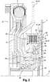
- the second example, presented at figure 2 differs in that the partition 53 forms a tight barrier between the springs 4 and the clutch 7.
- Such a partition 53 enables a wet clutch to be available without the wet clutch cooling oil polluting the environment of the springs.
- the partition 53 has an axial recess at the level of the clutch 5 making it possible to increase the space available for the clutch 5, in particular for the multi-disc assembly 22.
- the clutch 5 is therefore advantageously of the wet clutch type.
- the partition 53 can then define another supply network, comprising in particular a plurality of channels, for the passage of a cooling fluid of the clutch 5, such as gearbox oil. gears, intended to ensure the cooling and lubrication of the multidisc assembly.
- the channels can be evenly distributed around the X axis.
- the actuator 7 and the force transmission member 35 are also on the clutch side with respect to the partition 53.
- the intermediate element 6 bypasses the actuating member 7 and the force transmission member 35 from the inside to be fixed to the input disk holder 20 so that the element intermediate 6 does not interfere with the force transmission member 35.
- the intermediate element 6 comprises an arrangement different from that of the example of the figure 1 in that the web 8 extends radially as far as the hub portion 61 and in that the connection portion 9 is therefore not disposed between the web 8 and the hub portion 61.
- the connection portion 9 is disposed axially on the other side of the force transmission member 35 so that it is not necessary to provide an opening in the bearing surface on the assembly multidisk 22.
- the outer radial end 38 may be a continuous ring so that the bearing surface is continuous.
- the friction discs 23 are integral with the input disc holder 20 and they are radially outside the cylindrical skirt 27 and the plates are integral with the output disc holder 21 and they are radially inside the cylindrical skirt 28.
- the piston 43 has a “U” shape, in the plane of the figure.
- Such a piston makes it possible to act on the force transmission member radially outside the actuating chamber so that the actuator is extremely compact.
- the branches of the internal 65 and external 66 “U” radially frame the contour of the actuation chamber.
- the internal branch 65 is slidably mounted in the internal tube 46, the external branch 6 exerts an axial force oriented in the same direction as the force linked to the pressure on the internal branch 66.
- the rotating stop 49 is disposed radially outside the actuation chamber 48.
- the clutch 5 and its actuating member 7 are stacked radially towards the axis X.
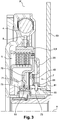
- the third example, presented at figure 3 differs from figure 1 by its mode of actuation.
- the actuator 7 also comprises the actuation chamber 48.
- the force transmission member 35 is moved by means of this actuation chamber which is delimited partly by said member 35.
- This actuator 7 is also called an actuator of the “piston” type.
- the actuating member 7 is integral in rotation with the intermediate element 6, via the hub portion 61.
- the actuating chamber 48 is sealed and filled with oil.
- the outline of the actuation chamber 48 is completed by an actuation chamber cover 69 integral in rotation with the force transmission member 35 by means of the hub portion 61 and fixed. axially so that the actuating chamber 48 and the oil it contains are in rotation.
- the actuating member 7 comprises a compensation chamber 70, sealed and filled with oil, delimited by the force transmission member 35 and by a cover balancing 71 integral in rotation with said transmission member 35.
- the balancing cover 71 is here defined by the connection portion 9 of the intermediate element 6.
- the force transmission member 35 forms a barrier between the two chambers 48, 70.
- the pressure chamber compensation 70 is intended to oppose the effects linked to the hydrodynamic oil pressure of the actuating chamber 48 on the transmission member 35.
- the force transmission member can thus be moved axially by varying the pressure d relative oil of the actuation 48 and compensation 70 chambers.
- the force transmission member 35, the actuating cover 69 and the balancing cover 71 are integral in rotation through the hub portion 61 of the intermediate element disposed radially inside and completing the contours of the two chambers 48, 70.
- the hub portion 61 can radially support the covers and the force transmission member.
- the hub portion 61 comprises slots 73 facing the bores, not shown, in at least one angular position of the actuating member 7.
- the bores can open radially.
- the holes are defined by the radial partition 53 for connecting the actuating chamber 48 and the compensation chamber 70, to the supply network.
- the intermediate element 6 is carried radially by means of two radial needle bearing bearings 55, mounted on the hub portion 61 and arranged axially on either side of the slots.
- the springs 4, the clutch 5 and the actuator 7 are stacked radially towards the axis X.
Description
La présente invention se rapporte au domaine des transmissions pour véhicule automobile. Elle se rapporte notamment à un dispositif de transmission destiné à être disposé, dans la chaine de transmission, entre un moteur thermique et une boîte de vitesses.The present invention relates to the field of transmissions for a motor vehicle. It relates in particular to a transmission device intended to be placed, in the transmission chain, between a heat engine and a gearbox.
Elle concerne notamment un dispositif de transmission pour un véhicule automobile de type hybride dans lequel une machine électrique est également disposée entre le moteur et la boîte de vitesses.It relates in particular to a transmission device for a hybrid type motor vehicle in which an electric machine is also placed between the engine and the gearbox.
Dans l'état de la technique, il est connu des ensembles de transmission, disposés entre la boîte de vitesses et le moteur thermique et comportant une machine électrique et un embrayage côté moteur permettant d'accoupler en rotation le vilebrequin du moteur thermique au rotor de la machine électrique. Ainsi, il est possible de couper le moteur thermique à chaque arrêt du véhicule et de le redémarrer grâce à la machine électrique. La machine électrique peut également constituer un frein électrique ou apporter un surplus d'énergie au moteur thermique pour l'assister ou éviter que celui-ci ne cale. La machine électrique peut également assurer l'entraînement du véhicule. Lorsque le moteur tourne, la machine électrique joue le rôle d'un alternateur. Un tel ensemble de transmission est notamment divulgué dans le document
Une telle machine électrique peut être en ligne avec l'axe de rotation de l'ensemble de transmission, comme décrit dans le document
Un moteur à explosion présente des acyclismes du fait des explosions se succédant dans les cylindres du moteur, la fréquence des acyclismes variant notamment en fonction du nombre de cylindres et de la vitesse de rotation du moteur. Afin de filtrer les vibrations engendrées par les acyclismes du moteur thermique, il est connu d'intégrer aux ensembles de transmission précités des amortisseurs d'oscillations de torsion à organes élastiques. A défaut de tels amortisseurs, des vibrations pénétrant dans la boîte de vitesses y provoqueraient en fonctionnement des chocs, bruits ou nuisances sonores particulièrement indésirables. De tels amortisseurs sont classiquement disposés entre le moteur thermique et la machine électrique et ils forment avec l'embrayage un dispositif de transmission de couple. Un tel dispositif est par exemple divulgué dans le document
Dans les développements actuels d'hybridation (« hybridisation » en anglais) des véhicules automobiles, il est demandé de disposer de chaine de transmission intégrant une source d'énergie électrique sans toutefois que cela n'impacte la compacité, notamment axiale, de ladite chaine de transmission. Cette recherche de compacité est à la base de l'invention.In the current developments of hybridization (“hybridization” in English) of motor vehicles, it is required to have a transmission chain incorporating a source of electrical energy without however this impacting the compactness, in particular axial, of said chain. transmission. This search for compactness is the basis of the invention.
Dans cette logique, le dispositif de transmission de couple entre le moteur thermique et la machine électrique décrit dans le document
L'invention vise à permettre de bénéficier d'un dispositif de transmission de couple permettant de concilier les exigences de compacité axiale sans toutefois dégrader la filtration des oscillations de torsion.The invention aims to make it possible to benefit from a torque transmission device making it possible to reconcile the requirements of axial compactness without, however, degrading the filtration of torsional oscillations.
L'invention y parvient à l'aide d'un dispositif de transmission de couple, notamment pour véhicule automobile, tel que défini par la revendication 1 et comprenant :
- un élément d'entrée de couple, apte à être couplé en rotation à un vilebrequin d'un moteur thermique,
- un élément de sortie de couple, apte à être couplé en rotation à au moins un arbre d'entrée d'une boîte de vitesses et/ou à une machine électrique tournante, l'élément d'entrée de couple étant apte à pivoter par rapport l'élément de sortie de couple autour d'un axe de rotation,
- au moins un organe de rappel élastique agissant à l'encontre de la rotation de l'élément de sortie par rapport à l'élément d'entrée,
- un embrayage, accouplant sélectivement et par friction les éléments d'entrée et de sortie,
- un élément intermédiaire agencé entre l'organe de rappel élastique et l'embrayage pour transmettre le couple, et
- un organe d'actionnement de l'embrayage,
- a torque input element, able to be coupled in rotation to a crankshaft of a heat engine,
- a torque output element, capable of being rotatably coupled to at least one input shaft of a gearbox and / or to a rotating electrical machine, the torque input element being capable of pivoting relative the torque output element around an axis of rotation,
- at least one elastic return member acting against the rotation of the output element with respect to the input element,
- a clutch, selectively and frictionally coupling the input and output elements,
- an intermediate element arranged between the elastic return member and the clutch to transmit the torque, and
- a clutch actuator,
Cet enchainement permet d'empiler les éléments radialement de sorte que l'on dispose d'un dispositif compact axialement. Cet enchainement permet donc de limiter l'impact du dispositif sur l'encombrement axial de la chaine de transmission. Disposer l'organe de rappel élastique le plus à l'extérieur radialement permet d'améliorer sa capacité de filtration.This sequence makes it possible to stack the elements radially so that there is an axially compact device. This sequence therefore makes it possible to limit the impact of the device on the axial size of the transmission chain. Having the radially outermost elastic return member improves its filtration capacity.
Au sens de l'invention, la succession radiale se comprend en terme de distance radiale.Within the meaning of the invention, the radial succession is understood in terms of radial distance.
Selon un aspect de l'invention, l'embrayage et l'organe d'actionnement peuvent être empilés radialement en rapprochement de l'axe de rotation. Selon cet aspect, il existe un plan perpendiculaire à l'axe de rotation qui coupe à la fois l'embrayage et l'organe d'actionnement de celui-ci. Cette disposition particulière participe à la compacité du dispositif.According to one aspect of the invention, the clutch and the actuating member can be stacked radially towards the axis of rotation. According to this aspect, there is a plane perpendicular to the axis of rotation which intersects both the clutch and the actuator thereof. This particular arrangement contributes to the compactness of the device.
Dans une disposition encore plus particulière, l'organe de rappel élastique, l'embrayage et l'organe d'actionnement peuvent être empilés radialement en rapprochement de l'axe de rotation. Selon cet aspect, il existe un plan perpendiculaire à l'axe de rotation qui coupe à la fois, l'organe de rappel élastique, l'embrayage et l'organe d'actionnement de celui-ci.In an even more particular arrangement, the elastic return member, the clutch and the actuator member can be stacked. radially in approach to the axis of rotation. According to this aspect, there is a plane perpendicular to the axis of rotation which intersects both the elastic return member, the clutch and the actuator thereof.
Une telle disposition permet de disposer les fonctions de filtration et de liaison sélective dans un même espace axial ce qui participe à la compacité du dispositif.Such an arrangement makes it possible to have the filtration and selective binding functions in the same axial space, which contributes to the compactness of the device.
Selon l'invention, l'embrayage comprend:
- un porte-disque d'entrée solidaire en rotation de l'élément intermédiaire,
- un porte-disque de sortie solidaire en rotation de l'élément de sortie,
- un ensemble multidisque comprenant au moins un disque de friction solidaire en rotation de l'un des porte-disques d'entrée et de sortie, au moins deux plateaux respectivement disposés de part et d'autre de chaque disque de friction, solidaires en rotation de l'autre des porte-disques d'entrée et de sortie et des garnitures de friction disposées entre les plateaux et un disque de friction, l'embrayage décrivant une position débrayée et une position embrayée dans laquelle lesdits plateaux et le disque de friction pincent les garnitures de friction de manière à transmettre un couple entre le porte-disque d'entrée et le porte-disque de sortie.
- an input disc holder rotatably secured to the intermediate element,
- an output disc holder rotatably attached to the output element,
- a multidisc assembly comprising at least one friction disc integral in rotation with one of the input and output disc carriers, at least two plates respectively placed on either side of each friction disc, integral in rotation with the other of the input and output disc carriers and the friction linings arranged between the plates and a friction disc, the clutch describing a disengaged position and an engaged position in which said plates and the friction disc clamp them. Friction linings so as to transmit torque between the input disc carrier and the output disc carrier.
Les garnitures peuvent être fixées sur les disques de friction, notamment par collage, notamment par rivetage, notamment par surmoulage. En variante, les garnitures sont fixées sur les plateaux.The linings can be fixed to the friction discs, in particular by gluing, in particular by riveting, in particular by overmolding. As a variant, the linings are fixed on the trays.
Chaque porte-disque peut synchroniser en rotation l'ensemble des plateaux ou l'ensemble des disques de friction. Les portes-disques peuvent comporter une jupe cylindrique sur lesquelles sont montées les plateaux et les disques de friction.Each disc holder can rotate all the plates or all the friction discs in rotation. The disc carriers may include a cylindrical skirt on which the plates and the friction discs are mounted.
Les plateaux et les disques peuvent coopérer avec les portes-disques selon une de leur périphérie radiale par complémentarité de forme. Les jupes cylindriques, les plateaux et les disques de friction peuvent par exemple être cannelés.The plates and the discs can cooperate with the disc holders along one of their radial periphery by form complementarity. The cylindrical skirts, the plates and the friction discs can for example be splined.
Selon un aspect non revendiqué, les plateaux peuvent être solidaires en rotation du porte-disque d'entrée et les disques de friction peuvent être solidaires du porte-disque de sortie. En variante, les plateaux peuvent être solidaires en rotation du porte-disque de sortie. Les disques peuvent être solidaires en rotation du porte-disque d'entrée.According to an unclaimed aspect, the plates may be integral in rotation with the input disk holder and the friction discs may be integral with the output disk carrier. As a variant, the plates may be integral in rotation with the output disc holder. The discs may be integral in rotation with the input disc holder.
Selon un aspect non revendiqué, les plateaux peuvent être radialement à l'intérieur de la jupe cylindrique du porte-disque d'entrée ou de sortie avec lequel ils sont solidaires en rotation. Les disques peuvent être radialement à l'extérieur de la jupe cylindrique du du porte-disque d'entrée ou de sortie avec lequel ils sont solidaires en rotation. En variante, les plateaux peuvent être radialement à l'extérieur de la jupe cylindrique du porte-disque d'entrée ou de sortie avec lequel ils sont solidaires en rotation. Les disques peuvent être radialement à l'intérieur de la jupe cylindrique du porte-disque d'entrée ou de sortie avec lequel ils sont solidaires en rotation.According to an aspect not claimed, the plates can be radially inside the cylindrical skirt of the input or output disc holder with which they are integral in rotation. The disks may be radially outside the cylindrical skirt of the input or output disk holder with which they are integral in rotation. As a variant, the plates may be radially outside the cylindrical skirt of the input or output disk holder with which they are integral in rotation. The disks can be radially inside the cylindrical skirt of the input or output disk holder with which they are integral in rotation.
L'embrayage peut être de type humide ou sec. De préférence, l'embrayage comporte entre 2 et 7 disques de friction, de préférence 4 disques de friction.The clutch can be wet or dry type. Preferably, the clutch comprises between 2 and 7 friction discs, preferably 4 friction discs.
Un tel embrayage multi-disques permet de limiter la hauteur radiale à laquelle il doit être disposé et de limiter son étendu axial. Cela permet de loger l'embrayage dans un espace intérieur à l'organe de rappel élastique.Such a multi-disc clutch makes it possible to limit the radial height at which it must be arranged and to limit its axial extent. This allows the clutch to be housed in a space inside the elastic return member.
Selon un autre aspect de l'invention, le dispositif peut comprendre un organe de transmission de force mobile axialement pour transmettre l'effort d'actionnement de l'organe d'actionnement vers l'embrayage, un organe de maintien en position débrayée étant interposé entre l'élément intermédiaire et l'organe de transmission de force.According to another aspect of the invention, the device may comprise a force transmission member axially movable to transmit the actuating force from the actuator member to the clutch, a member for maintaining in the disengaged position being interposed between the intermediate element and the force transmission member.
L'embrayage peut donc être de type « normalement ouvert ».The clutch can therefore be of the “normally open” type.
L'organe de transmission de force peut exercer un effort axial sur l'ensemble multidisque pour déplacer les plateaux vers les disques, notamment sur un plateau d'extrémité de l'ensemble multidisque. L'actionnement est ainsi de type « poussé ».The force transmission member can exert an axial force on the multi-disc assembly to move the plates towards the discs, in particular on an end plate of the multi-disc assembly. The actuation is thus of the “pushed” type.
L'organe de transmission de force peut présenter une extrémité radiale extérieure recourbée définissant une surface d'appui pour exercer l'effort axial sur l'ensemble multidisque. L'organe de transmission de force peut présenter une extrémité radiale intérieure avec lequel il coopère avec le reste de l'organe d'actionnement.The force transmission member may have a curved outer radial end defining a bearing surface for exerting the axial force on the multidisc assembly. The force transmission member may have an inner radial end with which it cooperates with the rest of the actuator member.
Cette surface d'appui peut venir en appui sur le plateau d'extrémité de l'ensemble multidisque. La surface d'appui peut être continue. L'extrémité radiale extérieure peut être une couronne continue de sorte que la surface d'appui est continue. L'extrémité radiale extérieure peut comporter une pluralité de doigts d'extension axiale et reparties autour de l'axe de sorte que la surface d'appui est discontinue.This support surface can come to rest on the end plate of the multidisc assembly. The bearing surface can be continuous. The outer radial end may be a continuous crown so that the bearing surface is continuous. The outer radial end may include a plurality of axially extending fingers and distributed around the axis so that the bearing surface is discontinuous.
Selon un aspect non revendiqué, chaque doigt de l'organe de transmission de force peut passer au travers d'ouvertures ménagées dans l'élément intermédiaire pour venir en contact de l'ensemble multidisque. Cela permet de disposer l'embrayage et son actionneur de part et d'autre de l'élément intermédiaire.According to an unclaimed aspect, each finger of the force transmission member can pass through openings made in the intermediate member to come into contact with the multidisc assembly. This allows the clutch and its actuator to be placed on either side of the intermediate element.
L'organe de transmission de force peut définir un espace intérieur dans lequel est disposé, au moins en partie, l'organe d'actionnement. Une telle forme permet de ne pas avoir à décaler axialement l'embrayage et son organe d'actionnement.The force transmission member may define an interior space in which the actuator is disposed, at least in part. Such a shape makes it possible not to have to axially offset the clutch and its actuator.
L'organe de transmission de force peut présenter trois coudes entre lesquelles sont interposées des portions planes.The force transmission member may have three bends between which are interposed flat portions.
L'organe de maintien peut être interposé entre deux portions planes de l'élément intermédiaire et de l'organe de transmission de force.The retaining member can be interposed between two flat portions of the intermediate element and of the force transmission member.
L'organe de maintien peut être une rondelle élastique, notamment une rondelle de type Belleville.The retaining member may be an elastic washer, in particular a Belleville type washer.
Selon un premier mode d'actionnement, l'organe d'actionnement peut comprendre une chambre d'actionnement. L'organe de transmission de force peut être déplacé au moyen de cette chambre d'actionnement délimitée en partie par ledit organe. Cet organe d'actionnement est aussi appelé actionneur de type « piston ».According to a first mode of actuation, the actuation member may comprise an actuation chamber. The force transmission member can be moved by means of this delimited actuation chamber partly by said organ. This actuator is also called an actuator of the “piston” type.
Dans ce mode d'actionnement, l'organe d'actionnement peut être solidaire en rotation de l'élément intermédiaire.In this mode of actuation, the actuating member may be integral in rotation with the intermediate element.
La chambre d'actionnement peut être étanche et remplie d'huile. L'organe de transmission de force peut être déplacé axialement par variation de pression d'huile dans la chambre d'actionnement.The actuation chamber can be sealed and filled with oil. The force transmission member can be moved axially by varying the oil pressure in the actuation chamber.
Le contour de la chambre d'actionnement peut être complété par un couvercle de chambre d'actionnement solidaire en rotation de l'organe de transmission de force et fixe axialement de sorte que la chambre et l'huile qu'elle contient sont en rotation.The outline of the actuation chamber may be completed by an actuation chamber cover integral in rotation with the force transmission member and fixed axially so that the chamber and the oil it contains are in rotation.
Associée à la chambre d'actionnement, l'organe d'actionnement peut comprendre une chambre de compensation délimitée par l'organe de transmission de force et par un couvercle d'équilibrage solidaire en rotation dudit l'organe de transmission. Cette chambre peut également être étanche et remplie d'huile. Le couvercle d'équilibrage peut être défini par l'élément intermédiaire.Associated with the actuating chamber, the actuating member may comprise a compensation chamber delimited by the force transmission member and by a balancing cover integral in rotation with said transmission member. This chamber can also be sealed and filled with oil. The balancing cover can be defined by the intermediate element.
L'organe de transmission de force peut former une barrière entre les deux chambres. La chambre de compensation est destinée à s'opposer aux effets liés à la pression d'huile hydrodynamique de la chambre d'actionnement sur l'organe de transmission. L'organe de transmission de force peut ainsi être déplacé axialement par variation de pression d'huile relative des chambres d'actionnement et de compensation.The force transmitting member can form a barrier between the two chambers. The compensation chamber is intended to oppose the effects related to the hydrodynamic oil pressure of the actuator chamber on the transmission member. The force transmission member can thus be moved axially by varying the relative oil pressure of the actuation and compensation chambers.
Les positions embrayée et débrayée de l'embrayage peuvent être associées respectivement à une position axiale du piston dite « embrayée » et à une pression fluidique relative dite « embrayée » respectivement à une position axiale du piston dite « débrayée » et à une pression fluidique relative dite « débrayée ».The engaged and disengaged positions of the clutch can be associated respectively with an axial position of the piston called “engaged” and with a relative fluidic pressure called “engaged” respectively with an axial position of the piston called “disengaged” and with a relative fluid pressure. called “disengaged”.
L'organe de transmission de force, le couvercle d'actionnement et le couvercle d'équilibrage peuvent être solidaires en rotation par l'intermédiaire d'une portion de moyeu, notamment de forme cylindrique, de l'élément intermédiaire disposée radialement à l'intérieur et complétant les contours des deux chambres. La portion de moyeu peut porter radialement les couvercles et l'organe de transmission de force.The force transmission member, the actuation cover and the balancing cover can be rotatably secured by means of of a hub portion, in particular of cylindrical shape, of the intermediate element disposed radially inside and completing the contours of the two chambers. The hub portion can radially support the covers and the force transmission member.
Selon un second mode d'actionnement conforme à l'invention, l'organe d'actionnement comprend un piston annulaire monté coulissant axialement à l'extérieur d'un tube interne, le piston et le tube formant une chambre d'actionnement. L'organe d'actionnement peut également comporter une butée tournante portée par le piston et coopérant avec l'organe de transmission de force. Cet organe d'actionnement est aussi appelé actionneur de type « CSC» (« Concentric Slave Cylinder » en anglais). La chambre d'actionnement peut être étanche et remplie d'huile.According to a second mode of actuation according to the invention, the actuating member comprises an annular piston mounted to slide axially outside an internal tube, the piston and the tube forming an actuation chamber. The actuating member may also include a rotating stop carried by the piston and cooperating with the force transmission member. This actuator is also called an actuator of the “CSC” type (“Concentric Slave Cylinder”). The actuation chamber can be sealed and filled with oil.
Dans ce mode d'actionnement, le piston et le tube sont fixes en rotation de sorte que la chambre d'actionnement et l'huile ne tourne pas.In this mode of actuation, the piston and the tube are fixed in rotation so that the actuation chamber and the oil do not rotate.
Selon un aspect non revendiqué, la butée tournante peut être un palier, notamment un palier à roulement. Le palier à roulement peut comporter une bague intérieure fixée au piston, une bague extérieure en appui contre l'organe de transmission de force et des corps roulants interposés entre la bague intérieure et la bague extérieure. De préférence, les corps roulants peuvent être des billes.According to an aspect not claimed, the rotary stop may be a bearing, in particular a rolling bearing. The rolling bearing may include an inner ring fixed to the piston, an outer ring bearing against the force transmission member and rolling bodies interposed between the inner ring and the outer ring. Preferably, the rolling bodies can be balls.
Le piston peut être de révolution autour de l'axe de rotation.The piston can be of revolution around the axis of rotation.
Selon un aspect de l'invention, le piston peut présenter une forme en « U », notamment dans un plan comprenant l'axe de rotation du dispositif.According to one aspect of the invention, the piston may have a “U” shape, in particular in a plane comprising the axis of rotation of the device.
Un tel piston permet d'agir sur l'organe de transmission de force radialement à l'extérieur de la chambre d'actionnement de sorte que l'actionneur est extrêmement compact.Such a piston makes it possible to act on the force transmission member radially outside the actuating chamber so that the actuator is extremely compact.
Selon cet aspect de l'invention, les branches du « U » peuvent encadrer radialement le contour de la chambre d'actionnement.According to this aspect of the invention, the branches of the “U” can radially frame the outline of the actuation chamber.
Selon cet aspect de l'invention, la butée tournante peut être disposée radialement à l'extérieur de la chambre d'actionnement. Il existe au moins un plan perpendiculaire à l'axe de rotation qui coupe la chambre d'actionnement et la butée tournante.According to this aspect of the invention, the rotating stopper can be disposed radially outside the actuation chamber. There is at least one plane perpendicular to the axis of rotation which intersects the actuation chamber and the rotating stop.
Les formes du piston et/ou de l'organe d'actionnement étant ainsi choisies de sorte que l'embrayage et son actionneur puissent s'empiler radialement ce qui contribue à la compacité axiale du dispositif.The shapes of the piston and / or of the actuating member thus being chosen so that the clutch and its actuator can be stacked radially, which contributes to the axial compactness of the device.
Dans ce mode de réalisation, les pressions fluidiques associées aux positions « embrayée » et « débrayée » sont les pressions de la chambre d'actionnement et non des pressions relatives entre deux chambres.In this embodiment, the fluid pressures associated with the “engaged” and “disengaged” positions are the pressures of the actuation chamber and not the relative pressures between two chambers.
Selon un autre aspect de l'invention, le dispositif peut comprendre un carter apte à être fixé sur la boîte de vitesses, notamment sur le carter de boîte de vitesses. Ce carter peut comprendre une cloison d'extension radiale. La cloison peut définir un réseau d'alimentation en fluide de l'organe d'actionnement. Le carter peut être fixe en rotation et en translation.According to another aspect of the invention, the device may comprise a casing capable of being fixed to the gearbox, in particular to the gearbox casing. This casing may include a radial extension partition. The partition may define a network for supplying fluid to the actuator. The housing can be fixed in rotation and in translation.
La cloison radiale, notamment son extrémité intérieure, peut comporter des perçages pour la connexion de la chambre d'actionnement, et éventuellement de la chambre de compensation, au réseau d'alimentation.The radial partition, in particular its inner end, may include holes for connecting the actuation chamber, and possibly the compensation chamber, to the supply network.
L'extrémité intérieure de la cloison peut comporter une portion cylindrique de sorte que la cloison radiale peut présenter un profil sensiblement en forme de « L ».The inner end of the partition may include a cylindrical portion so that the radial partition may have a profile that is substantially "L" shaped.
Selon le premier mode de réalisation d'actionnement, la portion de moyeu peut comporter des fentes en regard des perçages dans au moins une position angulaire de l'organe d'actionnement. Les perçages peuvent déboucher radialement.According to the first embodiment of actuation, the hub portion may include slots facing the bores in at least one angular position of the actuating member. The holes can open radially.
Selon le second mode d'actionnement, le tube interne peut être formé par l'extrémité intérieure de la cloison radiale. Le perçage peut déboucher axialement dans la chambre d'actionnement.According to the second mode of actuation, the inner tube can be formed by the inner end of the radial partition. The bore can open axially into the actuation chamber.
Selon un aspect de l'invention, la cloison peut former une barrière étanche entre l'organe de rappel élastique et l'embrayage.According to one aspect of the invention, the partition can form a tight barrier between the elastic return member and the clutch.
Une telle cloison permet de pouvoir disposer d'un embrayage humide sans que l'huile de refroidissement de l'embrayage humide ne vienne polluer l'environnement de l'organe de rappel élastique.Such a partition makes it possible to have a wet clutch without the cooling oil of the wet clutch polluting the environment of the elastic return member.
La cloison peut présenter un renfoncement axial au niveau de l'embrayage permettant d'augmenter l'espace disponible pour l'embrayage, notamment pour l'ensemble multidisque.The partition may have an axial recess at the level of the clutch making it possible to increase the space available for the clutch, in particular for the multi-disc assembly.
Selon un aspect de l'invention, l'élément intermédiaire peut être supporté radialement par le carter, notamment par la cloison, par l'intermédiaire d'au moins un palier d'appui radial.According to one aspect of the invention, the intermediate element can be supported radially by the casing, in particular by the partition, by means of at least one radial support bearing.
Le palier peut être à roulement, le palier peut être à aiguilles.The bearing may be rolling, the bearing may be needle bearing.
Le palier d'appui radial peut être disposé radialement à l'intérieur de l'organe d'actionnement, notamment radialement à l'intérieur de la chambre d'actionnement. Cet agencement permet de disposer les fonctions support et actionnement sur un même espace radial pour être compact axialement.The radial support bearing may be disposed radially inside the actuating member, in particular radially inside the actuating chamber. This arrangement makes it possible to arrange the support and actuation functions on the same radial space in order to be axially compact.
En particulier, dans le premier mode de réalisation, l'élément intermédiaire peut être porté radialement par l'intermédiaire d'au moins deux paliers d'appui radial, notamment à aiguilles, montée sur la portion de moyeu. Les paliers peuvent être disposés axialement de part et d'autre des perçages.In particular, in the first embodiment, the intermediate element can be carried radially by means of at least two radial support bearings, in particular needle bearings, mounted on the hub portion. The bearings can be arranged axially on either side of the bores.
L'élément d'entrée peut comporter deux rondelles de guidages encadrant axialement une pluralité de d'organes de rappel élastiques, tel que des ressorts courbes. Les rondelles de guidage peuvent se rapprocher localement entre les ressorts pour définir des zones d'appuis circonférentielles pour la coopération avec lesdits ressorts.The input element may include two guide washers axially framing a plurality of elastic return members, such as curved springs. The guide washers can come together locally between the springs to define circumferential support zones for cooperation with said springs.
L'élément d'entrée peut être centré sur l'élément de sortie par l'intermédiaire d'un roulement à aiguilles.The input element can be centered on the output element via a needle bearing.
L'élément d'entrée, notamment l'une des rondelles de guidages peut comporter une pluralité de trous pour le passage de rivets de fixation du vilebrequin. Sur cette même rondelle de guidage, radialement à l'extérieur, une couronne de démarrage peut être prévue.The input element, in particular one of the guide washers, may include a plurality of holes for the passage of crankshaft fixing rivets. On this same guide washer, radially on the outside, a starter ring can be provided.
L'élément intermédiaire peut comprendre un voile dont la périphérie radialement extérieure comporte des crans qui s'interposent circonférentiellement entre les ressorts. L'élément intermédiaire peut former un ensemble solidaire en rotation, notamment solidaire en rotation et en translation. Le voile et la portion de moyeu peuvent être directement reliés.The intermediate element may comprise a web, the radially outer periphery of which comprises notches which are interposed circumferentially between the springs. The intermediate element can form an integral unit in rotation, in particular integral in rotation and in translation. The web and the hub portion can be directly connected.
L'élément de sortie peut former une entrée en couple d'un double embrayage et/ou d'une machine électrique tournante.The output element can form a torque input of a double clutch and / or a rotating electrical machine.
L'invention sera mieux comprise, et d'autres buts, détails, caractéristiques et avantages de celle-ci apparaîtront plus clairement au cours de la description suivante de plusieurs modes de réalisation particuliers de l'invention, donnés uniquement à titre illustratif et non limitatif, en référence aux figures annexées.
- la
figure 1 est une vue en coupe axiale d'un exemple du dispositif selon l'invention dans un premier mode d'actionnement, - la
figure 2 est une vue en coupe axiale selon un deuxième exemple du dispositif dans le premier mode d'actionnement, et - la
figure 3 est une vue en coupe axiale selon un troisième exemple du dispositif selon l'invention dans un second mode d'actionnement.
- the
figure 1 is an axial sectional view of an example of the device according to the invention in a first mode of actuation, - the
figure 2 is an axial sectional view according to a second example of the device in the first mode of actuation, and - the
figure 3 is an axial sectional view according to a third example of the device according to the invention in a second mode of actuation.
En relation avec la
- un élément d'entrée de
couple 2, apte à être couplé en rotation à un vilebrequin d'un moteur thermique (non représenté), - un élément de sortie de
couple 3, apte à être couplé en rotation à au moins un arbre d'entrée d'une boîte de vitesses et/ou à une machine électrique tournante, l'élément d'entrée 2 étant apte à pivoter par rapport l'élément de sortie 3 autour d'un axe de rotation X,
- une pluralité d'organes de rappel élastique 4 agissant à l'encontre de la rotation de l'élément de sortie 3 par rapport à l'élément d'entrée 2,
un embrayage 5, accouplant sélectivement et par friction les éléments d'entrée et desortie un élément intermédiaire 6, solidaire en rotation et en translation, agencé entre les organes de rappel élastique 4et l'embrayage 5 pour transmettre le couple, et- un organe d'actionnement de l'embrayage 7.
- a
torque input element 2, able to be coupled in rotation to a crankshaft of a heat engine (not shown), - a
torque output element 3, capable of being coupled in rotation to at least one input shaft of a gearbox and / or to an electric machine rotating, theinput element 2 being able to pivot relative to theoutput element 3 about an axis of rotation X,
- a plurality of
elastic return members 4 acting against the rotation of theoutput element 3 with respect to theinput element 2, - a
clutch 5, selectively and frictionally coupling the input andoutput elements - an
intermediate element 6, integral in rotation and in translation, arranged between theelastic return members 4 and the clutch 5 to transmit the torque, and - a
clutch actuator 7.
Dans l'exemple considéré, l'élément d'entrée comporte deux rondelles de guidage, une rondelle de guidage avant 10 et une rondelle de guidage arrière 11. La rondelle de guidage 11 arrière est axialement disposée du côté du moteur thermique.In the example considered, the input element comprises two guide washers, a
Dans l'exemple considéré, les organes de rappel élastique 4 sont des ressorts courbes et ils sont encadrés par les rondelles de guidage 10, 11. Les rondelles de guidage sont fixées ensemble, par exemple par soudage, radialement à l'extérieur des ressorts 4.In the example considered, the
Dans l'exemple considéré, il est prévu une ou plusieurs gouttières qui s'interposent entre les rondelles de guidage et les ressorts lorsque ceux-ci sont centrifugés. Ces gouttières, par exemple en métal, épousent la forme des ressorts 4 et permettent d'en limiter l'usure.In the example considered, one or more gutters are provided which are interposed between the guide washers and the springs when the latter are centrifuged. These gutters, for example made of metal, follow the shape of the
Les rondelles de guidage 10, 11 peuvent se rapprocher localement entre les ressorts 4 pour définir des zones d'appuis circonférentielles pour la coopération avec lesdits ressorts. Ces zones d'appuis permettant de transmettre le couple entre l'élément d'entrée et les ressorts.The guide washers 10, 11 can come together locally between the
Une couronne de démarrage 15 est également fixée sur la rondelle de guidage arrière 11 au niveau de sa périphérie radialement extérieure. La rondelle de guidage arrière comporte aussi une pluralité de trous pour le passage de rivets ou de vis de fixation du vilebrequin. Ces vis 16 sont réparties tout autour de l'axe X.A
Enfin, l'extrémité radialement intérieure de la rondelle de guidage arrière 11 comprend une portion d'extension axiale pour coopérer avec l'élément de sortie par l'intermédiaire d'un roulement de centrage à aiguilles 18 afin d'assurer le centrage de l'élément d'entrée 2 sur l'élément de sortie 3.Finally, the radially inner end of the
Dans l'exemple considéré, l'élément intermédiaire 6 comprend un voile 8 dont la périphérie radialement extérieure comporte des crans (non visible dans le plan de coupe des figures) qui s'interposent circonférentiellement entre les ressorts. Ces crans définissent des zones d'appuis circonférentielles permettant de transmettre le couple entre les ressorts et l'élément de sortie.In the example considered, the
Toujours dans l'exemple considéré à la
Dans l'exemple considéré, l'embrayage 5 comprend:
- un porte-disque d'entrée 20 solidaire en rotation de l'élément intermédiaire 6, notamment d'une portion de
connexion 9 de l'élément intermédiaire 6, - un porte-disque de sortie 21 solidaire en rotation de l'élément de sortie 3, et
un ensemble multidisque 22 comprenant plusieurs disques defriction 23 solidaires en rotation du porte-disque de sortie 21, plusieursplateaux 24 disposés de part et d'autre de chaque disque defriction 23, solidaires en rotation du porte-disque d'entrée 20 et des garnitures de friction 25 disposées entre les plateaux 24 et les disques defriction 23.L'embrayage 5 décrit une position débrayée et une position embrayée dans laquelle les plateaux 24 et les disques defriction 23 pincent les garnitures de friction de manière à transmettre un couple entre le porte-disque d'entrée 20 et le porte-disque de sortie 21.
- an input disc holder 20 integral in rotation with the
intermediate element 6, in particular with aconnection portion 9 of theintermediate element 6, - an output disc holder 21 integral in rotation with the
output element 3, and - a
multi-disc assembly 22 comprisingseveral friction discs 23 integral in rotation with the output disc holder 21,several plates 24 arranged on either side of eachfriction disc 23, integral in rotation with the input disc holder 20 and friction linings 25 disposed between theplates 24 and thefriction discs 23. Theclutch 5 describes a disengaged position and an engaged position in which theplates 24 and thefriction discs 23 clamp the friction linings so as to transmit a torque between the input disc holder 20 and the output disc holder 21.
Les garnitures 25 sont fixées axialement de part et d'autres de chacun des disques de friction 23. Les garnitures 25 sont par exemple collées, par exemple rivetées, par exemple surmoulées. En variante, les garnitures peuvent être fixées sur les plateaux.The linings 25 are fixed axially on either side of each of the
Le porte-disque d'entrée 20 comporte également un élément de réaction 26 fixe axialement contre lequel est serré l'ensemble multidisque 22 en position embrayée. L'élément de réaction 26 prend la forme d'une couronne annulaire continue autour de l'axe X.The input disc carrier 20 also comprises a
Les porte-disques 20, 21 synchronisent en rotation respectivement l'ensemble des plateaux et l'ensemble des disques de friction. Les portes-disques comportent chacun une jupe cylindrique sur lesquelles sont montées les plateaux et les disques de friction.The disc carriers 20, 21 synchronize in rotation respectively all the plates and all the friction discs. The disc carriers each have a cylindrical skirt on which the plates and the friction discs are mounted.
Dans l'exemple considéré à la
Dans l'exemple considéré, la jupe cylindrique 27 est solidaire de l'élément intermédiaire 6, notamment de sa portion de connexion 9, par soudage.In the example considered, the cylindrical skirt 27 is secured to the
Les disques de friction 23 sont, quant à eux, radialement à l'extérieur de la jupe cylindrique 28 du porte-disque de sortie et ils sont solidaires en rotation par complémentarité de forme, par exemple par des cannelures.The
Dans l'exemple considéré à la
Dans l'exemple considéré, la jupe cylindrique de l'élément 28 de sortie est prolongée radialement vers l'intérieur par une paroi radial 29 de l'élément de sortie jusqu'à venir en prise avec un moyeu 30 de l'élément de sortie 3. Ce moyeu 30 porte le roulement de centrage 18.In the example considered, the cylindrical skirt of the output element 28 is extended radially inwards by a
Dans l'exemple considéré, un roulement, ici à aiguilles 31, est prévu entre la paroi 29 et l'élément intermédiaire 6 pour assurer le guidage axial de l'élément de sortie.In the example considered, a bearing, here with
Toujours dans l'exemple considéré à la
La rondelle élastique 36 est interposée entre deux portions planes de l'élément intermédiaire 6 et de l'organe de transmission de force 35. L'organe élastique 36 agit à l'encontre de l'organe d'actionnement 7 sur l'organe de transmission de force 35.The
L'organe de transmission de force 35 présente une extrémité radiale extérieure 38 recourbée définissant une surface d'appui pour exercer l'effort axial sur un plateau d'extrémité de l'ensemble multidisque 22 pour déplacer les plateaux vers les disques. L'actionnement est ainsi de type « poussé ».The
L'extrémité radiale 38 peut comporter une pluralité de doigts 39 d'extension axiale et reparties autour de l'axe de sorte que la surface d'appui est discontinue. Chaque doigt 39 peut passer au travers d'une ouverture 40 ménagée dans l'élément intermédiaire 6, en particulier dans la potion intermédiaire 9, pour venir en contact de l'ensemble multidisque 22, l'embrayage et son actionneur étant de part et d'autre de l'élément intermédiaire.The
L'organe de transmission de force 35 définit un espace intérieur 43 dans lequel est disposé, au moins en partie, l'organe d'actionnement 7. Cette espace intérieur est formé par un renfoncement 44 de l'organe de transmission de force 35. L'élément intermédiaire 6 et la paroi radiale 29 reproduisent la forme de ce renfoncement axial pour permettre un débattement axial suffisant au fonctionnement de l'organe d'actionnement 7.The
L'organe de transmission de force 35 présente trois coudes reliés par des portions planes.The
L'organe de transmission de force 35 présente une extrémité radiale intérieure 40 avec lequel il coopère avec l'organe d'actionnement, comme on le verra par la suite.The
Dans l'exemple considéré à la
L'organe d'actionnement 7 comprend un piston annulaire 45, qui peut être de révolution autour de l'axe X, monté coulissant axialement à l'extérieur d'un tube interne 46, le piston et le tube formant une chambre d'actionnement 48. L'organe d'actionnement comporte également une butée tournante 49 portée par le piston et coopérant avec l'organe de transmission de force 35. Cet organe d'actionnement est aussi appelé actionneur de type « CSC» (« Concentric Slave Cylinder » en anglais). La chambre d'actionnement 48 est étanche et remplie d'huile.The
Dans l'exemple considéré, la butée tournante 49 peut être un palier, notamment un palier à roulement. Le palier à roulement peut comporter une bague intérieure fixée au piston, une bague extérieure en appui contre l'organe de transmission de force et des corps roulants interposés entre la bague intérieure et la bague extérieure.In the example considered, the rotating
Dans l'exemple considéré, le dispositif 1 comprend aussi un carter 52 apte à être fixé sur la boîte de vitesses, notamment sur le carter de boîte de vitesses. Le carter est fixe en rotation et en translation.In the example considered, the device 1 also comprises a casing 52 capable of being fixed to the gearbox, in particular to the gearbox casing. The housing is fixed in rotation and in translation.
Le carter 52 comprend une cloison 53 d'extension radiale qui comportant une portion cylindrique à son extrémité radialement intérieure de sorte que la cloison radiale peut présenter un profil sensiblement en forme de « L ».The casing 52 comprises a
Dans l'exemple considéré à la
Dans l'exemple considéré, la cloison 53 définit un réseau d'alimentation en fluide, non représenté, de l'organe d'actionnement 7.In the example considered, the
Dans l'exemple considéré, l'extrémité intérieure de la cloison 53, comporte au moins un perçage, non représenté, pour la connexion de la chambre d'actionnement 48 au réseau d'alimentation. Ce perçage peut déboucher axialement dans la chambre d'actionnement 48.In the example considered, the inner end of the
Dans l'exemple considéré, l'élément intermédiaire 6 est supporté radialement par la cloison 53, par l'intermédiaire d'un palier d'appui radial 55, ici un palier à roulement. Le palier d'appui radial 55 peut être disposé radialement à l'intérieur de l'organe d'actionnement 7, en particulier de la chambre d'actionnement 48. Le palier d'appui radial 55 permet de reprendre le poids et le balourd radial de l'embrayage.In the example considered, the
Dans l'exemple considéré, le palier d'appui radial 55 comporte une bague externe 58 montée à l'intérieur de la cloison 53 et immobilisée axialement par un épaulement 59 formé par la portion cylindrique de ladite cloison 53, une bague interne 60 montée autour d'une portion de moyeu cylindrique 61 définie par l'extrémité radialement intérieure de l'organe intermédiaire 6 et immobilisée axialement, dans le sens opposé à la bague externe, par un anneau élastique 62, par exemple un jonc d'arrêt ou un « circlip », montée de façon amovible, dans une gorge 63 de la portion cylindrique de l'élément intermédiaire 6. Entre les bagues sont montés des moyens de roulement 64, ici des billes.In the example considered, the radial support bearing 55 comprises an
Dans l'exemple considéré, l'élément intermédiaire 6 comprend donc, en rapprochement de l'axe X, le voile 8 solidaire en rotation par exemple par cannelures à une portion de connexion 9 qui prend une forme sensiblement identique à celle de l'organe de transmission de force 35. Portion de connexion 9 elle-même fixée, par exemple par soudage, à la portion de moyeu 61.In the example considered, the
Dans l'exemple du dispositif 1 tel qu'il vient d'être décrit, les ressorts 4, l'embrayage 5 et l'organe d'actionnement 7 se succèdent radialement. Cet enchaînement permet d'empiler les éléments radialement de sorte que l'on dispose d'un dispositif compact axialement. Les ressorts sont plus éloignés de l'axe X que l'embrayage 5 et l'embrayage 5 est radialement plus éloigné que son organe d'actionnement 7.In the example of the device 1 as has just been described, the
En particulier, dans cet exemple de réalisation, les ressorts 4, l'embrayage 5 et l'organe d'actionnement 7 sont empilés radialement en rapprochement de l'axe X. Il existe un plan P perpendiculaire à l'axe X qui coupe à la fois, les ressorts 4, l'embrayage 5 et l'organe d'actionnement 7 de celui-ci. Une telle disposition permet de disposer les fonctions de filtration et de liaison sélective dans un même espace axial ce qui participe à la compacité du dispositif 1.In particular, in this exemplary embodiment, the
Le deuxième exemple, présenté à la
Une telle cloison 53 permet de pouvoir disposer d'un embrayage humide sans que l'huile de refroidissement de l'embrayage humide ne vienne polluer l'environnement des ressorts.Such a
La cloison 53 présente un renfoncement axial au niveau de l'embrayage 5 permettant d'augmenter l'espace disponible pour l'embrayage 5, notamment pour l'ensemble multidisque 22.The
Dans l'exemple de la
Dans l'exemple considéré, la cloison 53 peut alors définir un autre réseau d'alimentation, comportant notamment une pluralité de canaux, pour le passage d'un fluide de refroidissement de l'embrayage 5, tel que de l'huile de boîte de vitesses, destiné à assurer le refroidissement et la lubrification de l'ensemble multidisque. Les canaux peuvent être équitablement répartis autour de l'axe X.In the example considered, the
Dans l'exemple considéré, l'organe d'actionnement 7 et l'organe de transmission de force 35 sont également du côté de l'embrayage par rapport à la cloison 53.In the example considered, the
Dans l'exemple considéré, l'élément intermédiaire 6 contourne l'organe d'actionnement 7 et l'organe de transmission de force 35 par l'intérieur pour être fixé sur le porte-disque d'entrée 20 de sorte que l'élément intermédiaire 6 n'interfère pas avec l'organe de transmission de force 35.In the example considered, the
Dans l'exemple considéré, l'élément intermédiaire 6 comprend un agencement différent de celui de l'exemple de la
Dans l'exemple considéré, l'extrémité radiale extérieure 38 peut être une couronne continue de sorte que la surface d'appui est continue.In the example considered, the outer
Dans l'exemple considéré, les disques de friction 23 sont solidaires du porte-disque d'entrée 20 et ils sont radialement à l'extérieur de la jupe cylindrique 27 et les plateaux sont solidaires du porte-disque de sortie 21 et ils sont radialement à l'intérieur de la jupe cylindrique 28.In the example considered, the
Dans l'exemple considéré, le piston 43 présente une forme en « U », dans le plan de la figure. Un tel piston permet d'agir sur l'organe de transmission de force radialement à l'extérieur de la chambre d'actionnement de sorte que l'actionneur est extrêmement compact.In the example considered, the
Les branches du « U » interne 65 et externe 66 encadrent radialement le contour de la chambre d'actionnement. La branche interne 65 est montée coulissante dans le tube interne 46, la branche externe 6 exerce un effort axial orienté dans le même sens que l'effort lié à la pression sur la branche interne 66.The branches of the internal 65 and external 66 “U” radially frame the contour of the actuation chamber. The
La butée tournante 49 est disposée radialement à l'extérieur de la chambre d'actionnement 48.The rotating
Dans l'exemple considéré, l'embrayage 5 et son organe d'actionnement 7 sont empilés radialement en rapprochement de l'axe X.In the example considered, the
Le troisième exemple, présenté à la
Dans ce mode, défini comme le premier mode d'actionnement, l'organe d'actionnement 7 comprend également la chambre d'actionnement 48. L'organe de transmission de force 35 est déplacé au moyen de cette chambre d'actionnement qui est délimitée en partie par ledit organe 35. Cet organe d'actionnement 7 est aussi appelé actionneur de type « piston ».In this mode, defined as the first mode of actuation, the
Il n'existe pas de piston ni de butée tournante dans ce mode de réalisation dans ce mode d'actionnement.There is no piston or rotary stop in this embodiment in this mode of actuation.
Dans l'exemple considéré, l'organe d'actionnement 7 est solidaire en rotation de l'élément intermédiaire 6, par l'intermédiaire de la portion de moyeu 61. La chambre d'actionnement 48 est étanche et remplie d'huile.In the example considered, the actuating
Dans l'exemple considéré, le contour de la chambre d'actionnement 48 est complété par un couvercle de chambre d'actionnement 69 solidaire en rotation de l'organe de transmission de force 35 par l'intermédiaire de la portion de moyeu 61 et fixe axialement de sorte que la chambre d'actionnement 48 et l'huile qu'elle contient sont en rotation.In the example considered, the outline of the
Dans l'exemple considéré, associée à la chambre d'actionnement 48, l'organe d'actionnement 7 comprend une chambre de compensation 70, étanche et remplie d'huile, délimitée par l'organe de transmission de force 35 et par un couvercle d'équilibrage 71 solidaire en rotation dudit l'organe de transmission 35. Le couvercle d'équilibrage 71 est ici défini par la portion de connexion 9 de l'élément intermédiaire 6.In the example considered, associated with the
Dans l'exemple considéré, l'organe de transmission de force 35 forme une barrière entre les deux chambres 48, 70. La chambre de compensation 70 est destinée à s'opposer aux effets liés à la pression d'huile hydrodynamique de la chambre d'actionnement 48 sur l'organe de transmission 35. L'organe de transmission de force peut ainsi être déplacé axialement par variation de pression d'huile relative des chambres d'actionnement 48 et de compensation 70.In the example considered, the
L'organe de transmission de force 35, le couvercle d'actionnement 69 et le couvercle d'équilibrage 71 sont solidaires en rotation par l'intermédiaire de la portion de moyeu 61 de l'élément intermédiaire disposé radialement à l'intérieur et complétant les contours des deux chambres 48, 70. La portion de moyeu 61 peut porter radialement les couvercles et l'organe de transmission de force.The
Dans l'exemple considéré, la portion de moyeu 61 comporte des fentes 73 en regard des perçages, non représenté, dans au moins une position angulaire de l'organe d'actionnement 7. Les perçages peuvent déboucher radialement. Les perçages sont définis par la cloison radiale 53 pour la connexion de la chambre d'actionnement 48 et de la chambre de compensation 70, au réseau d'alimentation.In the example under consideration, the
Dans l'exemple considéré, l'élément intermédiaire 6 est porté radialement par l'intermédiaire de deux paliers d'appui radial à aiguilles 55, montée sur la portion de moyeu 61 et disposés axialement de part et d'autre des fentes.In the example considered, the
En particulier, dans cet exemple de réalisation, les ressorts 4, l'embrayage 5 et l'organe d'actionnement 7 sont empilés radialement en rapprochement de l'axe X. Il existe un plan P' perpendiculaire à l'axe X qui coupe à la fois, les ressorts 4, l'embrayage 5 et l'organe d'actionnement 7 de celui-ci. Une telle disposition permet de disposer les fonctions de filtration et de liaison sélective dans un même espace axial ce qui participe à la compacité du dispositif 1.In particular, in this exemplary embodiment, the
Claims (11)
- A torque transmission device (1), in particular for a motor vehicle, comprising:- a torque input element (2), which can be coupled in rotation to a crankshaft of an internal combustion engine;- a torque output element (3), which can be coupled in rotation to at least one input shaft of a gearbox and/or to a rotary electrical machine, the torque input element being able to pivot relative to the torque output element, around an axis of rotation;- at least one resilient return unit (4) which acts against the rotation of the output element relative to the input element;- a clutch (5), which couples the input and output elements selectively and by means of friction;- an intermediate element (6) arranged between the resilient return unit and the clutch for transmission of the torque; and- a clutch actuation unit (7),the resilient return unit, the clutch and the actuation unit succeed one another radially, characterized in that:
the clutch (5) comprises :- an input disk holder (20) which is integral in rotation with the intermediate element;- an output disk holder (21) which is integral in rotation with the output element;- a multi-disk assembly (22) comprising at least one friction disk (23) which is integral in rotation with one of the input and output disk holders, at least two plates (24) which are positioned respectively on both sides of each friction disk, and are integral in rotation with the other one of the input and output disk holders, and friction linings (25) which are positioned between the plates and a friction disk, with the clutch (5) describing a disengaged position and an engaged position in which said plates and the friction disk grip the friction linings, such as to transmit torque between the input disk holder (20) and the output disk holder (21),the actuation unit (7) comprises an annular piston (45) which is fitted such as to slide axially on the exterior of an inner tube (46), with the piston and the tube forming an actuation chamber (48), and a rotary stop (49) which is supported by the piston, and cooperates with the force transmission unit. - The device (1) as claimed in claim 1, the clutch (5) and the actuation unit (7) being stacked radially going towards the axis of rotation X.
- The device (1) as claimed in one of the preceding claims, the resilient return unit (4), the clutch (5) and the actuation unit (7) being stacked radially going towards the axis of rotation X.
- The device (1) as claimed in claim 1, comprising a force transmission unit (35) which is mobile axially in order to transmit the force of actuation of the actuation unit (7) towards the clutch (5), with a unit (36) for retention in the disengaged position being interposed between the intermediate element (6) and the force transmission unit (35).
- The device (1) as claimed in the preceding claim, the actuation unit (7) comprising an actuation chamber (48), the force transmission unit being displaced by means of this actuation chamber which is delimited partly by said force transmission unit.
- The device (1) as claimed in claim 1, the piston (45) having a form of a "U".
- The device (1) as claimed in one of claims 1 and 6, comprising a housing (52) which can be secured on the gearbox, comprising a radial extension partition (53), the partition defining at least one network for supply of the actuation chamber (48).
- The device (1) as claimed in the preceding claim, the partition (53) forming a sealed barrier between the resilient return unit (4) and the clutch (5).
- The device (1) as claimed in one of the preceding claims, the intermediate element (6) being supported radially by the housing (52), by means of at least one radial support bearing (55).
- The device (1) as claimed in the preceding claim, the radial support bearing (55) being positioned radially in the interior of the actuation unit (7).
- The device (1) as claimed in one of the preceding claims, the output element (3) forming a torque input of a double clutch and/or a rotary electrical machine.
Applications Claiming Priority (2)
| Application Number | Priority Date | Filing Date | Title |
|---|---|---|---|
| FR1660466A FR3058098B1 (en) | 2016-10-27 | 2016-10-27 | TRANSMISSION DEVICE FOR HYBRID VEHICLE |
| PCT/EP2017/077475 WO2018078029A1 (en) | 2016-10-27 | 2017-10-26 | Transmission device for a hybrid vehicle |
Publications (2)
| Publication Number | Publication Date |
|---|---|
| EP3532324A1 EP3532324A1 (en) | 2019-09-04 |
| EP3532324B1 true EP3532324B1 (en) | 2020-09-16 |
Family
ID=58314354
Family Applications (1)
| Application Number | Title | Priority Date | Filing Date |
|---|---|---|---|
| EP17787212.4A Active EP3532324B1 (en) | 2016-10-27 | 2017-10-26 | Transmission device for a hybrid vehicle |
Country Status (4)
| Country | Link |
|---|---|
| EP (1) | EP3532324B1 (en) |
| CN (1) | CN109890639B (en) |
| FR (1) | FR3058098B1 (en) |
| WO (1) | WO2018078029A1 (en) |
Families Citing this family (8)
| Publication number | Priority date | Publication date | Assignee | Title |
|---|---|---|---|---|
| FR3073784B1 (en) * | 2017-11-22 | 2020-08-28 | Valeo Embrayages | HYBRID VEHICLE TRANSMISSION DEVICE |
| FR3073787A1 (en) * | 2017-11-22 | 2019-05-24 | Valeo Embrayages | TRANSMISSION DEVICE FOR A HYBRID VEHICLE |
| CN111601727B (en) * | 2017-11-22 | 2024-02-20 | 法雷奥离合器公司 | Transmission for hybrid vehicle |
| WO2019102099A2 (en) * | 2017-11-22 | 2019-05-31 | Valeo Embrayages | Transmission device for a hybrid vehicle |
| DE102018222514B4 (en) * | 2018-12-20 | 2022-08-04 | Audi Ag | drive device |
| DE102020120523B4 (en) * | 2020-08-04 | 2023-09-07 | Schaeffler Technologies AG & Co. KG | Separating clutch with an axis of rotation for a drive train |
| FR3117954B1 (en) | 2020-12-17 | 2022-11-25 | Valeo Embrayages | TORQUE CUT CLUTCH |
| WO2022170464A1 (en) * | 2021-02-09 | 2022-08-18 | 舍弗勒技术股份两合公司 | Torsional vibration damper and motor vehicle |
Citations (11)
| Publication number | Priority date | Publication date | Assignee | Title |
|---|---|---|---|---|
| JP2000304065A (en) | 1999-08-24 | 2000-10-31 | Nsk Warner Kk | Starting clutch |
| FR2830589A1 (en) | 2001-10-08 | 2003-04-11 | Valeo | Hybrid vehicle twin clutch transmission assembly with rotating electrical machine, in which electrical machine is between the two clutches and its rotor and second clutch are supported and centered by a bearing on the machine casing |
| JP2003262236A (en) | 2002-03-07 | 2003-09-19 | Toyota Motor Corp | Clutch device |
| US20050205379A1 (en) | 2004-03-22 | 2005-09-22 | Tryon Eric S | Torsional damper for electrically-variable transmission with lock-out clutch assembly |
| US20080121488A1 (en) | 2006-11-27 | 2008-05-29 | Tomoyuki Miyazaki | Starting clutch |
| US20080142331A1 (en) | 2006-12-15 | 2008-06-19 | Tomoyuki Miyazaki | Starting clutch |
| WO2010081453A2 (en) | 2009-01-19 | 2010-07-22 | Luk Lamellen Und Kupplungsbau Beteiligungs Kg | Hybrid module for a drive train of a vehicle |
| DE102010051911A1 (en) | 2009-11-25 | 2011-06-01 | Schaeffler Technologies Gmbh & Co. Kg | Multiple coupling device, component, assemblies and methods of assembly |
| DE102010004711A1 (en) | 2010-01-11 | 2011-07-14 | GETRAG Getriebe- und Zahnradfabrik Hermann Hagenmeyer GmbH & Cie KG, 74199 | Hybrid drive strand for motor car, has electric machine assigned to partial gear box, and friction clutch arranged between another two friction clutches and drive unit i.e. combustion engine |
| DE102012220443A1 (en) | 2011-11-30 | 2013-06-06 | Schaeffler Technologies AG & Co. KG | Wet dual clutch for use in motor vehicle i.e. passenger car, has vibration damper comprising input side and output side that is arranged in wet area, and clutch systems arranged laterally to rod, where damper is connected with housing |
| FR3015380A1 (en) | 2013-12-19 | 2015-06-26 | Valeo Embrayages | TRANSMISSION ASSEMBLY FOR A HYBRID VEHICLE EQUIPPED WITH A PENDULAR SHOCK ABSORBER |
Family Cites Families (5)
| Publication number | Priority date | Publication date | Assignee | Title |
|---|---|---|---|---|
| EP1548313B2 (en) * | 2003-12-23 | 2016-09-28 | Schaeffler Technologies AG & Co. KG | Torque transmission device and drive train comprising such a device |
| US7489114B2 (en) * | 2004-11-19 | 2009-02-10 | Aisin Aw Co., Ltd. | Hybrid vehicle drive unit |
| US7926635B2 (en) * | 2006-12-27 | 2011-04-19 | Schaeffler Technologies Gmbh & Co. Kg | Piston assembly and a force transfer device, particularly a force transfer device with a piston assembly |
| US8434607B2 (en) * | 2010-02-23 | 2013-05-07 | GM Global Technology Operations LLC | Compact torque transmitting assembly |
| US9157495B2 (en) * | 2013-10-24 | 2015-10-13 | Ford Global Technologies, Llc | Torque converter having integrated flex plate for hybrid electric vehicle |
-
2016
- 2016-10-27 FR FR1660466A patent/FR3058098B1/en active Active
-
2017
- 2017-10-26 EP EP17787212.4A patent/EP3532324B1/en active Active
- 2017-10-26 WO PCT/EP2017/077475 patent/WO2018078029A1/en unknown
- 2017-10-26 CN CN201780067156.3A patent/CN109890639B/en active Active
Patent Citations (11)
| Publication number | Priority date | Publication date | Assignee | Title |
|---|---|---|---|---|
| JP2000304065A (en) | 1999-08-24 | 2000-10-31 | Nsk Warner Kk | Starting clutch |
| FR2830589A1 (en) | 2001-10-08 | 2003-04-11 | Valeo | Hybrid vehicle twin clutch transmission assembly with rotating electrical machine, in which electrical machine is between the two clutches and its rotor and second clutch are supported and centered by a bearing on the machine casing |
| JP2003262236A (en) | 2002-03-07 | 2003-09-19 | Toyota Motor Corp | Clutch device |
| US20050205379A1 (en) | 2004-03-22 | 2005-09-22 | Tryon Eric S | Torsional damper for electrically-variable transmission with lock-out clutch assembly |
| US20080121488A1 (en) | 2006-11-27 | 2008-05-29 | Tomoyuki Miyazaki | Starting clutch |
| US20080142331A1 (en) | 2006-12-15 | 2008-06-19 | Tomoyuki Miyazaki | Starting clutch |
| WO2010081453A2 (en) | 2009-01-19 | 2010-07-22 | Luk Lamellen Und Kupplungsbau Beteiligungs Kg | Hybrid module for a drive train of a vehicle |
| DE102010051911A1 (en) | 2009-11-25 | 2011-06-01 | Schaeffler Technologies Gmbh & Co. Kg | Multiple coupling device, component, assemblies and methods of assembly |
| DE102010004711A1 (en) | 2010-01-11 | 2011-07-14 | GETRAG Getriebe- und Zahnradfabrik Hermann Hagenmeyer GmbH & Cie KG, 74199 | Hybrid drive strand for motor car, has electric machine assigned to partial gear box, and friction clutch arranged between another two friction clutches and drive unit i.e. combustion engine |
| DE102012220443A1 (en) | 2011-11-30 | 2013-06-06 | Schaeffler Technologies AG & Co. KG | Wet dual clutch for use in motor vehicle i.e. passenger car, has vibration damper comprising input side and output side that is arranged in wet area, and clutch systems arranged laterally to rod, where damper is connected with housing |
| FR3015380A1 (en) | 2013-12-19 | 2015-06-26 | Valeo Embrayages | TRANSMISSION ASSEMBLY FOR A HYBRID VEHICLE EQUIPPED WITH A PENDULAR SHOCK ABSORBER |
Also Published As
| Publication number | Publication date |
|---|---|
| CN109890639A (en) | 2019-06-14 |
| CN109890639B (en) | 2022-10-21 |
| EP3532324A1 (en) | 2019-09-04 |
| FR3058098A1 (en) | 2018-05-04 |
| FR3058098B1 (en) | 2024-01-19 |
| WO2018078029A1 (en) | 2018-05-03 |
Similar Documents
| Publication | Publication Date | Title |
|---|---|---|
| EP3532324B1 (en) | Transmission device for a hybrid vehicle | |
| FR3069201B1 (en) | TRANSMISSION DEVICE FOR A HYBRID VEHICLE | |
| FR3069296A1 (en) | TRANSMISSION DEVICE FOR A HYBRID VEHICLE | |
| EP3757414A1 (en) | Torque transmission device | |
| FR3090774A1 (en) | Transmission device for motor vehicle | |
| FR2791405A1 (en) | Clutch unit with two clutch discs for vehicle engine has intermediate pressure plate between clutch discs, and counter pressure plate on clutch input part | |
| EP3899300A1 (en) | Transmission device for a motor vehicle | |
| WO2017149161A1 (en) | Torque transmission device | |
| FR3015605A1 (en) | TRANSMISSION ASSEMBLY EQUIPPED WITH A PENDULUM SHOCK ABSORBER EXTENDING RADIALLY OUTSIDE A CLUTCH DEVICE | |
| EP3710298A1 (en) | Transmission device for a hybrid vehicle | |
| WO2019102099A2 (en) | Transmission device for a hybrid vehicle | |
| FR3079572A1 (en) | TRANSMISSION DEVICE FOR MOTOR VEHICLE | |
| WO2018104139A1 (en) | Torsion damping device | |
| FR3079455A1 (en) | TRANSMISSION DEVICE FOR A HYBRID VEHICLE | |
| FR3069199A1 (en) | TRANSMISSION DEVICE FOR A HYBRID VEHICLE | |
| WO2018002500A1 (en) | Torque-transmission device, in particular for a motor vehicle | |
| FR3073784A1 (en) | TRANSMISSION DEVICE FOR A HYBRID VEHICLE | |
| FR3069200A1 (en) | TRANSMISSION DEVICE FOR A HYBRID VEHICLE | |
| FR3073788A1 (en) | TRANSMISSION DEVICE FOR A HYBRID VEHICLE | |
| WO2019211244A1 (en) | Transmission device for a motor vehicle | |
| FR3084024A1 (en) | TRANSMISSION DEVICE FOR HYBRID VEHICLE | |
| FR3078377A1 (en) | TRANSMISSION DEVICE FOR A HYBRID VEHICLE | |
| FR3080896A1 (en) | TRANSMISSION DEVICE FOR MOTOR VEHICLE | |
| FR3073914A1 (en) | TRANSMISSION DEVICE FOR A HYBRID VEHICLE | |
| FR3080898A1 (en) | TRANSMISSION DEVICE FOR MOTOR VEHICLE |
Legal Events
| Date | Code | Title | Description |
|---|---|---|---|
| STAA | Information on the status of an ep patent application or granted ep patent |
Free format text: STATUS: UNKNOWN |
|
| STAA | Information on the status of an ep patent application or granted ep patent |
Free format text: STATUS: THE INTERNATIONAL PUBLICATION HAS BEEN MADE |
|
| PUAI | Public reference made under article 153(3) epc to a published international application that has entered the european phase |
Free format text: ORIGINAL CODE: 0009012 |
|
| STAA | Information on the status of an ep patent application or granted ep patent |
Free format text: STATUS: REQUEST FOR EXAMINATION WAS MADE |
|
| 17P | Request for examination filed |
Effective date: 20190327 |
|
| AK | Designated contracting states |
Kind code of ref document: A1 Designated state(s): AL AT BE BG CH CY CZ DE DK EE ES FI FR GB GR HR HU IE IS IT LI LT LU LV MC MK MT NL NO PL PT RO RS SE SI SK SM TR |
|
| AX | Request for extension of the european patent |
Extension state: BA ME |
|
| DAV | Request for validation of the european patent (deleted) | ||
| DAX | Request for extension of the european patent (deleted) | ||
| GRAP | Despatch of communication of intention to grant a patent |
Free format text: ORIGINAL CODE: EPIDOSNIGR1 |
|
| STAA | Information on the status of an ep patent application or granted ep patent |
Free format text: STATUS: GRANT OF PATENT IS INTENDED |
|
| INTG | Intention to grant announced |
Effective date: 20200508 |
|
| RIN1 | Information on inventor provided before grant (corrected) |
Inventor name: DOLE, ARNAUD Inventor name: THIBAUT, FRANCOIS Inventor name: BACQ, VINCENT Inventor name: COMMEINE, EMMANUEL Inventor name: LEBAS, GILLES |
|
| GRAS | Grant fee paid |
Free format text: ORIGINAL CODE: EPIDOSNIGR3 |
|
| GRAA | (expected) grant |
Free format text: ORIGINAL CODE: 0009210 |
|
| STAA | Information on the status of an ep patent application or granted ep patent |
Free format text: STATUS: THE PATENT HAS BEEN GRANTED |
|
| AK | Designated contracting states |
Kind code of ref document: B1 Designated state(s): AL AT BE BG CH CY CZ DE DK EE ES FI FR GB GR HR HU IE IS IT LI LT LU LV MC MK MT NL NO PL PT RO RS SE SI SK SM TR |
|
| REG | Reference to a national code |
Ref country code: GB Ref legal event code: FG4D Free format text: NOT ENGLISH |
|
| REG | Reference to a national code |
Ref country code: CH Ref legal event code: EP |
|
| REG | Reference to a national code |
Ref country code: DE Ref legal event code: R096 Ref document number: 602017023839 Country of ref document: DE |
|
| REG | Reference to a national code |
Ref country code: IE Ref legal event code: FG4D Free format text: LANGUAGE OF EP DOCUMENT: FRENCH |
|
| REG | Reference to a national code |
Ref country code: AT Ref legal event code: REF Ref document number: 1313851 Country of ref document: AT Kind code of ref document: T Effective date: 20201015 |
|
| PG25 | Lapsed in a contracting state [announced via postgrant information from national office to epo] |
Ref country code: FI Free format text: LAPSE BECAUSE OF FAILURE TO SUBMIT A TRANSLATION OF THE DESCRIPTION OR TO PAY THE FEE WITHIN THE PRESCRIBED TIME-LIMIT Effective date: 20200916 Ref country code: HR Free format text: LAPSE BECAUSE OF FAILURE TO SUBMIT A TRANSLATION OF THE DESCRIPTION OR TO PAY THE FEE WITHIN THE PRESCRIBED TIME-LIMIT Effective date: 20200916 Ref country code: SE Free format text: LAPSE BECAUSE OF FAILURE TO SUBMIT A TRANSLATION OF THE DESCRIPTION OR TO PAY THE FEE WITHIN THE PRESCRIBED TIME-LIMIT Effective date: 20200916 Ref country code: GR Free format text: LAPSE BECAUSE OF FAILURE TO SUBMIT A TRANSLATION OF THE DESCRIPTION OR TO PAY THE FEE WITHIN THE PRESCRIBED TIME-LIMIT Effective date: 20201217 Ref country code: NO Free format text: LAPSE BECAUSE OF FAILURE TO SUBMIT A TRANSLATION OF THE DESCRIPTION OR TO PAY THE FEE WITHIN THE PRESCRIBED TIME-LIMIT Effective date: 20201216 Ref country code: BG Free format text: LAPSE BECAUSE OF FAILURE TO SUBMIT A TRANSLATION OF THE DESCRIPTION OR TO PAY THE FEE WITHIN THE PRESCRIBED TIME-LIMIT Effective date: 20201216 |
|
| REG | Reference to a national code |
Ref country code: AT Ref legal event code: MK05 Ref document number: 1313851 Country of ref document: AT Kind code of ref document: T Effective date: 20200916 |
|
| REG | Reference to a national code |
Ref country code: NL Ref legal event code: MP Effective date: 20200916 |
|
| PG25 | Lapsed in a contracting state [announced via postgrant information from national office to epo] |
Ref country code: LV Free format text: LAPSE BECAUSE OF FAILURE TO SUBMIT A TRANSLATION OF THE DESCRIPTION OR TO PAY THE FEE WITHIN THE PRESCRIBED TIME-LIMIT Effective date: 20200916 Ref country code: RS Free format text: LAPSE BECAUSE OF FAILURE TO SUBMIT A TRANSLATION OF THE DESCRIPTION OR TO PAY THE FEE WITHIN THE PRESCRIBED TIME-LIMIT Effective date: 20200916 |
|
| REG | Reference to a national code |
Ref country code: LT Ref legal event code: MG4D |
|
| PG25 | Lapsed in a contracting state [announced via postgrant information from national office to epo] |
Ref country code: SM Free format text: LAPSE BECAUSE OF FAILURE TO SUBMIT A TRANSLATION OF THE DESCRIPTION OR TO PAY THE FEE WITHIN THE PRESCRIBED TIME-LIMIT Effective date: 20200916 Ref country code: LT Free format text: LAPSE BECAUSE OF FAILURE TO SUBMIT A TRANSLATION OF THE DESCRIPTION OR TO PAY THE FEE WITHIN THE PRESCRIBED TIME-LIMIT Effective date: 20200916 Ref country code: CZ Free format text: LAPSE BECAUSE OF FAILURE TO SUBMIT A TRANSLATION OF THE DESCRIPTION OR TO PAY THE FEE WITHIN THE PRESCRIBED TIME-LIMIT Effective date: 20200916 Ref country code: PT Free format text: LAPSE BECAUSE OF FAILURE TO SUBMIT A TRANSLATION OF THE DESCRIPTION OR TO PAY THE FEE WITHIN THE PRESCRIBED TIME-LIMIT Effective date: 20210118 Ref country code: RO Free format text: LAPSE BECAUSE OF FAILURE TO SUBMIT A TRANSLATION OF THE DESCRIPTION OR TO PAY THE FEE WITHIN THE PRESCRIBED TIME-LIMIT Effective date: 20200916 Ref country code: EE Free format text: LAPSE BECAUSE OF FAILURE TO SUBMIT A TRANSLATION OF THE DESCRIPTION OR TO PAY THE FEE WITHIN THE PRESCRIBED TIME-LIMIT Effective date: 20200916 |
|
| PG25 | Lapsed in a contracting state [announced via postgrant information from national office to epo] |
Ref country code: ES Free format text: LAPSE BECAUSE OF FAILURE TO SUBMIT A TRANSLATION OF THE DESCRIPTION OR TO PAY THE FEE WITHIN THE PRESCRIBED TIME-LIMIT Effective date: 20200916 Ref country code: AL Free format text: LAPSE BECAUSE OF FAILURE TO SUBMIT A TRANSLATION OF THE DESCRIPTION OR TO PAY THE FEE WITHIN THE PRESCRIBED TIME-LIMIT Effective date: 20200916 Ref country code: AT Free format text: LAPSE BECAUSE OF FAILURE TO SUBMIT A TRANSLATION OF THE DESCRIPTION OR TO PAY THE FEE WITHIN THE PRESCRIBED TIME-LIMIT Effective date: 20200916 Ref country code: PL Free format text: LAPSE BECAUSE OF FAILURE TO SUBMIT A TRANSLATION OF THE DESCRIPTION OR TO PAY THE FEE WITHIN THE PRESCRIBED TIME-LIMIT Effective date: 20200916 Ref country code: IS Free format text: LAPSE BECAUSE OF FAILURE TO SUBMIT A TRANSLATION OF THE DESCRIPTION OR TO PAY THE FEE WITHIN THE PRESCRIBED TIME-LIMIT Effective date: 20210116 |
|
| REG | Reference to a national code |
Ref country code: CH Ref legal event code: PL |
|
| REG | Reference to a national code |
Ref country code: DE Ref legal event code: R026 Ref document number: 602017023839 Country of ref document: DE |
|
| PLBI | Opposition filed |
Free format text: ORIGINAL CODE: 0009260 |
|
| PG25 | Lapsed in a contracting state [announced via postgrant information from national office to epo] |
Ref country code: MC Free format text: LAPSE BECAUSE OF FAILURE TO SUBMIT A TRANSLATION OF THE DESCRIPTION OR TO PAY THE FEE WITHIN THE PRESCRIBED TIME-LIMIT Effective date: 20200916 Ref country code: LU Free format text: LAPSE BECAUSE OF NON-PAYMENT OF DUE FEES Effective date: 20201026 Ref country code: SK Free format text: LAPSE BECAUSE OF FAILURE TO SUBMIT A TRANSLATION OF THE DESCRIPTION OR TO PAY THE FEE WITHIN THE PRESCRIBED TIME-LIMIT Effective date: 20200916 |
|
| REG | Reference to a national code |
Ref country code: BE Ref legal event code: MM Effective date: 20201031 |
|
| 26 | Opposition filed |
Opponent name: SCHAEFFLER TECHNOLOGIES AG & CO. KG Effective date: 20210611 |
|
| PLAX | Notice of opposition and request to file observation + time limit sent |
Free format text: ORIGINAL CODE: EPIDOSNOBS2 |
|
| PG25 | Lapsed in a contracting state [announced via postgrant information from national office to epo] |
Ref country code: BE Free format text: LAPSE BECAUSE OF NON-PAYMENT OF DUE FEES Effective date: 20201031 Ref country code: CH Free format text: LAPSE BECAUSE OF NON-PAYMENT OF DUE FEES Effective date: 20201031 Ref country code: SI Free format text: LAPSE BECAUSE OF FAILURE TO SUBMIT A TRANSLATION OF THE DESCRIPTION OR TO PAY THE FEE WITHIN THE PRESCRIBED TIME-LIMIT Effective date: 20200916 Ref country code: DK Free format text: LAPSE BECAUSE OF FAILURE TO SUBMIT A TRANSLATION OF THE DESCRIPTION OR TO PAY THE FEE WITHIN THE PRESCRIBED TIME-LIMIT Effective date: 20200916 Ref country code: LI Free format text: LAPSE BECAUSE OF NON-PAYMENT OF DUE FEES Effective date: 20201031 |
|
| PG25 | Lapsed in a contracting state [announced via postgrant information from national office to epo] |
Ref country code: IT Free format text: LAPSE BECAUSE OF FAILURE TO SUBMIT A TRANSLATION OF THE DESCRIPTION OR TO PAY THE FEE WITHIN THE PRESCRIBED TIME-LIMIT Effective date: 20200916 Ref country code: IE Free format text: LAPSE BECAUSE OF NON-PAYMENT OF DUE FEES Effective date: 20201026 |
|
| PLBB | Reply of patent proprietor to notice(s) of opposition received |
Free format text: ORIGINAL CODE: EPIDOSNOBS3 |
|
| PG25 | Lapsed in a contracting state [announced via postgrant information from national office to epo] |
Ref country code: TR Free format text: LAPSE BECAUSE OF FAILURE TO SUBMIT A TRANSLATION OF THE DESCRIPTION OR TO PAY THE FEE WITHIN THE PRESCRIBED TIME-LIMIT Effective date: 20200916 Ref country code: MT Free format text: LAPSE BECAUSE OF FAILURE TO SUBMIT A TRANSLATION OF THE DESCRIPTION OR TO PAY THE FEE WITHIN THE PRESCRIBED TIME-LIMIT Effective date: 20200916 Ref country code: CY Free format text: LAPSE BECAUSE OF FAILURE TO SUBMIT A TRANSLATION OF THE DESCRIPTION OR TO PAY THE FEE WITHIN THE PRESCRIBED TIME-LIMIT Effective date: 20200916 |
|
| GBPC | Gb: european patent ceased through non-payment of renewal fee |
Effective date: 20211026 |
|
| PG25 | Lapsed in a contracting state [announced via postgrant information from national office to epo] |
Ref country code: MK Free format text: LAPSE BECAUSE OF FAILURE TO SUBMIT A TRANSLATION OF THE DESCRIPTION OR TO PAY THE FEE WITHIN THE PRESCRIBED TIME-LIMIT Effective date: 20200916 |
|
| PG25 | Lapsed in a contracting state [announced via postgrant information from national office to epo] |
Ref country code: GB Free format text: LAPSE BECAUSE OF NON-PAYMENT OF DUE FEES Effective date: 20211026 |
|
| APBM | Appeal reference recorded |
Free format text: ORIGINAL CODE: EPIDOSNREFNO |
|
| APBP | Date of receipt of notice of appeal recorded |
Free format text: ORIGINAL CODE: EPIDOSNNOA2O |
|
| PLAB | Opposition data, opponent's data or that of the opponent's representative modified |
Free format text: ORIGINAL CODE: 0009299OPPO |
|
| APAH | Appeal reference modified |
Free format text: ORIGINAL CODE: EPIDOSCREFNO |
|
| APBM | Appeal reference recorded |
Free format text: ORIGINAL CODE: EPIDOSNREFNO |
|
| APBP | Date of receipt of notice of appeal recorded |
Free format text: ORIGINAL CODE: EPIDOSNNOA2O |
|
| R26 | Opposition filed (corrected) |
Opponent name: SCHAEFFLER TECHNOLOGIES AG & CO. KG Effective date: 20210611 |
|
| APBQ | Date of receipt of statement of grounds of appeal recorded |
Free format text: ORIGINAL CODE: EPIDOSNNOA3O |
|
| PG25 | Lapsed in a contracting state [announced via postgrant information from national office to epo] |
Ref country code: NL Free format text: LAPSE BECAUSE OF NON-PAYMENT OF DUE FEES Effective date: 20200923 |
|
| P01 | Opt-out of the competence of the unified patent court (upc) registered |
Effective date: 20230528 |
|
| APAH | Appeal reference modified |
Free format text: ORIGINAL CODE: EPIDOSCREFNO |
|
| PGFP | Annual fee paid to national office [announced via postgrant information from national office to epo] |
Ref country code: FR Payment date: 20231023 Year of fee payment: 7 Ref country code: DE Payment date: 20231011 Year of fee payment: 7 |