EP3532324B1 - Getriebevorrichtung für hybridfahrzeug - Google Patents
Getriebevorrichtung für hybridfahrzeug Download PDFInfo
- Publication number
- EP3532324B1 EP3532324B1 EP17787212.4A EP17787212A EP3532324B1 EP 3532324 B1 EP3532324 B1 EP 3532324B1 EP 17787212 A EP17787212 A EP 17787212A EP 3532324 B1 EP3532324 B1 EP 3532324B1
- Authority
- EP
- European Patent Office
- Prior art keywords
- clutch
- rotation
- actuation
- input
- unit
- Prior art date
- Legal status (The legal status is an assumption and is not a legal conclusion. Google has not performed a legal analysis and makes no representation as to the accuracy of the status listed.)
- Active
Links
- 230000005540 biological transmission Effects 0.000 title claims description 74
- 238000005192 partition Methods 0.000 claims description 27
- 230000004888 barrier function Effects 0.000 claims description 5
- 238000002485 combustion reaction Methods 0.000 claims description 2
- 230000014759 maintenance of location Effects 0.000 claims 1
- 235000021183 entrée Nutrition 0.000 description 17
- 238000005096 rolling process Methods 0.000 description 10
- 239000000969 carrier Substances 0.000 description 5
- 238000001914 filtration Methods 0.000 description 5
- 239000012530 fluid Substances 0.000 description 4
- 238000001816 cooling Methods 0.000 description 3
- 210000000056 organ Anatomy 0.000 description 3
- 230000010355 oscillation Effects 0.000 description 3
- 238000003466 welding Methods 0.000 description 3
- 230000000712 assembly Effects 0.000 description 2
- 238000000429 assembly Methods 0.000 description 2
- 230000008901 benefit Effects 0.000 description 2
- 238000006243 chemical reaction Methods 0.000 description 2
- 230000008878 coupling Effects 0.000 description 2
- 238000010168 coupling process Methods 0.000 description 2
- 238000005859 coupling reaction Methods 0.000 description 2
- 230000000694 effects Effects 0.000 description 2
- 238000009396 hybridization Methods 0.000 description 2
- 230000035939 shock Effects 0.000 description 2
- 239000007858 starting material Substances 0.000 description 2
- 239000006096 absorbing agent Substances 0.000 description 1
- 238000004026 adhesive bonding Methods 0.000 description 1
- 239000012809 cooling fluid Substances 0.000 description 1
- 230000000593 degrading effect Effects 0.000 description 1
- 238000011161 development Methods 0.000 description 1
- 230000018109 developmental process Effects 0.000 description 1
- 238000004880 explosion Methods 0.000 description 1
- 238000009432 framing Methods 0.000 description 1
- 230000003116 impacting effect Effects 0.000 description 1
- 238000005461 lubrication Methods 0.000 description 1
- 239000002184 metal Substances 0.000 description 1
Images

Classifications
-
- B—PERFORMING OPERATIONS; TRANSPORTING
- B60—VEHICLES IN GENERAL
- B60K—ARRANGEMENT OR MOUNTING OF PROPULSION UNITS OR OF TRANSMISSIONS IN VEHICLES; ARRANGEMENT OR MOUNTING OF PLURAL DIVERSE PRIME-MOVERS IN VEHICLES; AUXILIARY DRIVES FOR VEHICLES; INSTRUMENTATION OR DASHBOARDS FOR VEHICLES; ARRANGEMENTS IN CONNECTION WITH COOLING, AIR INTAKE, GAS EXHAUST OR FUEL SUPPLY OF PROPULSION UNITS IN VEHICLES
- B60K6/00—Arrangement or mounting of plural diverse prime-movers for mutual or common propulsion, e.g. hybrid propulsion systems comprising electric motors and internal combustion engines ; Control systems therefor, i.e. systems controlling two or more prime movers, or controlling one of these prime movers and any of the transmission, drive or drive units Informative references: mechanical gearings with secondary electric drive F16H3/72; arrangements for handling mechanical energy structurally associated with the dynamo-electric machine H02K7/00; machines comprising structurally interrelated motor and generator parts H02K51/00; dynamo-electric machines not otherwise provided for in H02K see H02K99/00
- B60K6/20—Arrangement or mounting of plural diverse prime-movers for mutual or common propulsion, e.g. hybrid propulsion systems comprising electric motors and internal combustion engines ; Control systems therefor, i.e. systems controlling two or more prime movers, or controlling one of these prime movers and any of the transmission, drive or drive units Informative references: mechanical gearings with secondary electric drive F16H3/72; arrangements for handling mechanical energy structurally associated with the dynamo-electric machine H02K7/00; machines comprising structurally interrelated motor and generator parts H02K51/00; dynamo-electric machines not otherwise provided for in H02K see H02K99/00 the prime-movers consisting of electric motors and internal combustion engines, e.g. HEVs
- B60K6/42—Arrangement or mounting of plural diverse prime-movers for mutual or common propulsion, e.g. hybrid propulsion systems comprising electric motors and internal combustion engines ; Control systems therefor, i.e. systems controlling two or more prime movers, or controlling one of these prime movers and any of the transmission, drive or drive units Informative references: mechanical gearings with secondary electric drive F16H3/72; arrangements for handling mechanical energy structurally associated with the dynamo-electric machine H02K7/00; machines comprising structurally interrelated motor and generator parts H02K51/00; dynamo-electric machines not otherwise provided for in H02K see H02K99/00 the prime-movers consisting of electric motors and internal combustion engines, e.g. HEVs characterised by the architecture of the hybrid electric vehicle
- B60K6/48—Parallel type
-
- B—PERFORMING OPERATIONS; TRANSPORTING
- B60—VEHICLES IN GENERAL
- B60K—ARRANGEMENT OR MOUNTING OF PROPULSION UNITS OR OF TRANSMISSIONS IN VEHICLES; ARRANGEMENT OR MOUNTING OF PLURAL DIVERSE PRIME-MOVERS IN VEHICLES; AUXILIARY DRIVES FOR VEHICLES; INSTRUMENTATION OR DASHBOARDS FOR VEHICLES; ARRANGEMENTS IN CONNECTION WITH COOLING, AIR INTAKE, GAS EXHAUST OR FUEL SUPPLY OF PROPULSION UNITS IN VEHICLES
- B60K6/00—Arrangement or mounting of plural diverse prime-movers for mutual or common propulsion, e.g. hybrid propulsion systems comprising electric motors and internal combustion engines ; Control systems therefor, i.e. systems controlling two or more prime movers, or controlling one of these prime movers and any of the transmission, drive or drive units Informative references: mechanical gearings with secondary electric drive F16H3/72; arrangements for handling mechanical energy structurally associated with the dynamo-electric machine H02K7/00; machines comprising structurally interrelated motor and generator parts H02K51/00; dynamo-electric machines not otherwise provided for in H02K see H02K99/00
- B60K6/20—Arrangement or mounting of plural diverse prime-movers for mutual or common propulsion, e.g. hybrid propulsion systems comprising electric motors and internal combustion engines ; Control systems therefor, i.e. systems controlling two or more prime movers, or controlling one of these prime movers and any of the transmission, drive or drive units Informative references: mechanical gearings with secondary electric drive F16H3/72; arrangements for handling mechanical energy structurally associated with the dynamo-electric machine H02K7/00; machines comprising structurally interrelated motor and generator parts H02K51/00; dynamo-electric machines not otherwise provided for in H02K see H02K99/00 the prime-movers consisting of electric motors and internal combustion engines, e.g. HEVs
- B60K6/22—Arrangement or mounting of plural diverse prime-movers for mutual or common propulsion, e.g. hybrid propulsion systems comprising electric motors and internal combustion engines ; Control systems therefor, i.e. systems controlling two or more prime movers, or controlling one of these prime movers and any of the transmission, drive or drive units Informative references: mechanical gearings with secondary electric drive F16H3/72; arrangements for handling mechanical energy structurally associated with the dynamo-electric machine H02K7/00; machines comprising structurally interrelated motor and generator parts H02K51/00; dynamo-electric machines not otherwise provided for in H02K see H02K99/00 the prime-movers consisting of electric motors and internal combustion engines, e.g. HEVs characterised by apparatus, components or means specially adapted for HEVs
- B60K6/38—Arrangement or mounting of plural diverse prime-movers for mutual or common propulsion, e.g. hybrid propulsion systems comprising electric motors and internal combustion engines ; Control systems therefor, i.e. systems controlling two or more prime movers, or controlling one of these prime movers and any of the transmission, drive or drive units Informative references: mechanical gearings with secondary electric drive F16H3/72; arrangements for handling mechanical energy structurally associated with the dynamo-electric machine H02K7/00; machines comprising structurally interrelated motor and generator parts H02K51/00; dynamo-electric machines not otherwise provided for in H02K see H02K99/00 the prime-movers consisting of electric motors and internal combustion engines, e.g. HEVs characterised by apparatus, components or means specially adapted for HEVs characterised by the driveline clutches
- B60K6/387—Actuated clutches, i.e. clutches engaged or disengaged by electric, hydraulic or mechanical actuating means
-
- B—PERFORMING OPERATIONS; TRANSPORTING
- B60—VEHICLES IN GENERAL
- B60K—ARRANGEMENT OR MOUNTING OF PROPULSION UNITS OR OF TRANSMISSIONS IN VEHICLES; ARRANGEMENT OR MOUNTING OF PLURAL DIVERSE PRIME-MOVERS IN VEHICLES; AUXILIARY DRIVES FOR VEHICLES; INSTRUMENTATION OR DASHBOARDS FOR VEHICLES; ARRANGEMENTS IN CONNECTION WITH COOLING, AIR INTAKE, GAS EXHAUST OR FUEL SUPPLY OF PROPULSION UNITS IN VEHICLES
- B60K6/00—Arrangement or mounting of plural diverse prime-movers for mutual or common propulsion, e.g. hybrid propulsion systems comprising electric motors and internal combustion engines ; Control systems therefor, i.e. systems controlling two or more prime movers, or controlling one of these prime movers and any of the transmission, drive or drive units Informative references: mechanical gearings with secondary electric drive F16H3/72; arrangements for handling mechanical energy structurally associated with the dynamo-electric machine H02K7/00; machines comprising structurally interrelated motor and generator parts H02K51/00; dynamo-electric machines not otherwise provided for in H02K see H02K99/00
- B60K6/20—Arrangement or mounting of plural diverse prime-movers for mutual or common propulsion, e.g. hybrid propulsion systems comprising electric motors and internal combustion engines ; Control systems therefor, i.e. systems controlling two or more prime movers, or controlling one of these prime movers and any of the transmission, drive or drive units Informative references: mechanical gearings with secondary electric drive F16H3/72; arrangements for handling mechanical energy structurally associated with the dynamo-electric machine H02K7/00; machines comprising structurally interrelated motor and generator parts H02K51/00; dynamo-electric machines not otherwise provided for in H02K see H02K99/00 the prime-movers consisting of electric motors and internal combustion engines, e.g. HEVs
- B60K6/22—Arrangement or mounting of plural diverse prime-movers for mutual or common propulsion, e.g. hybrid propulsion systems comprising electric motors and internal combustion engines ; Control systems therefor, i.e. systems controlling two or more prime movers, or controlling one of these prime movers and any of the transmission, drive or drive units Informative references: mechanical gearings with secondary electric drive F16H3/72; arrangements for handling mechanical energy structurally associated with the dynamo-electric machine H02K7/00; machines comprising structurally interrelated motor and generator parts H02K51/00; dynamo-electric machines not otherwise provided for in H02K see H02K99/00 the prime-movers consisting of electric motors and internal combustion engines, e.g. HEVs characterised by apparatus, components or means specially adapted for HEVs
- B60K6/40—Arrangement or mounting of plural diverse prime-movers for mutual or common propulsion, e.g. hybrid propulsion systems comprising electric motors and internal combustion engines ; Control systems therefor, i.e. systems controlling two or more prime movers, or controlling one of these prime movers and any of the transmission, drive or drive units Informative references: mechanical gearings with secondary electric drive F16H3/72; arrangements for handling mechanical energy structurally associated with the dynamo-electric machine H02K7/00; machines comprising structurally interrelated motor and generator parts H02K51/00; dynamo-electric machines not otherwise provided for in H02K see H02K99/00 the prime-movers consisting of electric motors and internal combustion engines, e.g. HEVs characterised by apparatus, components or means specially adapted for HEVs characterised by the assembly or relative disposition of components
-
- F—MECHANICAL ENGINEERING; LIGHTING; HEATING; WEAPONS; BLASTING
- F16—ENGINEERING ELEMENTS AND UNITS; GENERAL MEASURES FOR PRODUCING AND MAINTAINING EFFECTIVE FUNCTIONING OF MACHINES OR INSTALLATIONS; THERMAL INSULATION IN GENERAL
- F16D—COUPLINGS FOR TRANSMITTING ROTATION; CLUTCHES; BRAKES
- F16D25/00—Fluid-actuated clutches
- F16D25/06—Fluid-actuated clutches in which the fluid actuates a piston incorporated in, i.e. rotating with the clutch
- F16D25/062—Fluid-actuated clutches in which the fluid actuates a piston incorporated in, i.e. rotating with the clutch the clutch having friction surfaces
- F16D25/063—Fluid-actuated clutches in which the fluid actuates a piston incorporated in, i.e. rotating with the clutch the clutch having friction surfaces with clutch members exclusively moving axially
- F16D25/0635—Fluid-actuated clutches in which the fluid actuates a piston incorporated in, i.e. rotating with the clutch the clutch having friction surfaces with clutch members exclusively moving axially with flat friction surfaces, e.g. discs
- F16D25/0638—Fluid-actuated clutches in which the fluid actuates a piston incorporated in, i.e. rotating with the clutch the clutch having friction surfaces with clutch members exclusively moving axially with flat friction surfaces, e.g. discs with more than two discs, e.g. multiple lamellae
-
- F—MECHANICAL ENGINEERING; LIGHTING; HEATING; WEAPONS; BLASTING
- F16—ENGINEERING ELEMENTS AND UNITS; GENERAL MEASURES FOR PRODUCING AND MAINTAINING EFFECTIVE FUNCTIONING OF MACHINES OR INSTALLATIONS; THERMAL INSULATION IN GENERAL
- F16D—COUPLINGS FOR TRANSMITTING ROTATION; CLUTCHES; BRAKES
- F16D25/00—Fluid-actuated clutches
- F16D25/08—Fluid-actuated clutches with fluid-actuated member not rotating with a clutching member
- F16D25/082—Fluid-actuated clutches with fluid-actuated member not rotating with a clutching member the line of action of the fluid-actuated members co-inciding with the axis of rotation
-
- F—MECHANICAL ENGINEERING; LIGHTING; HEATING; WEAPONS; BLASTING
- F16—ENGINEERING ELEMENTS AND UNITS; GENERAL MEASURES FOR PRODUCING AND MAINTAINING EFFECTIVE FUNCTIONING OF MACHINES OR INSTALLATIONS; THERMAL INSULATION IN GENERAL
- F16F—SPRINGS; SHOCK-ABSORBERS; MEANS FOR DAMPING VIBRATION
- F16F15/00—Suppression of vibrations in systems; Means or arrangements for avoiding or reducing out-of-balance forces, e.g. due to motion
- F16F15/10—Suppression of vibrations in rotating systems by making use of members moving with the system
- F16F15/12—Suppression of vibrations in rotating systems by making use of members moving with the system using elastic members or friction-damping members, e.g. between a rotating shaft and a gyratory mass mounted thereon
- F16F15/131—Suppression of vibrations in rotating systems by making use of members moving with the system using elastic members or friction-damping members, e.g. between a rotating shaft and a gyratory mass mounted thereon the rotating system comprising two or more gyratory masses
- F16F15/13121—Suppression of vibrations in rotating systems by making use of members moving with the system using elastic members or friction-damping members, e.g. between a rotating shaft and a gyratory mass mounted thereon the rotating system comprising two or more gyratory masses characterised by clutch arrangements, e.g. for activation; integrated with clutch members, e.g. pressure member
-
- B—PERFORMING OPERATIONS; TRANSPORTING
- B60—VEHICLES IN GENERAL
- B60K—ARRANGEMENT OR MOUNTING OF PROPULSION UNITS OR OF TRANSMISSIONS IN VEHICLES; ARRANGEMENT OR MOUNTING OF PLURAL DIVERSE PRIME-MOVERS IN VEHICLES; AUXILIARY DRIVES FOR VEHICLES; INSTRUMENTATION OR DASHBOARDS FOR VEHICLES; ARRANGEMENTS IN CONNECTION WITH COOLING, AIR INTAKE, GAS EXHAUST OR FUEL SUPPLY OF PROPULSION UNITS IN VEHICLES
- B60K6/00—Arrangement or mounting of plural diverse prime-movers for mutual or common propulsion, e.g. hybrid propulsion systems comprising electric motors and internal combustion engines ; Control systems therefor, i.e. systems controlling two or more prime movers, or controlling one of these prime movers and any of the transmission, drive or drive units Informative references: mechanical gearings with secondary electric drive F16H3/72; arrangements for handling mechanical energy structurally associated with the dynamo-electric machine H02K7/00; machines comprising structurally interrelated motor and generator parts H02K51/00; dynamo-electric machines not otherwise provided for in H02K see H02K99/00
- B60K6/20—Arrangement or mounting of plural diverse prime-movers for mutual or common propulsion, e.g. hybrid propulsion systems comprising electric motors and internal combustion engines ; Control systems therefor, i.e. systems controlling two or more prime movers, or controlling one of these prime movers and any of the transmission, drive or drive units Informative references: mechanical gearings with secondary electric drive F16H3/72; arrangements for handling mechanical energy structurally associated with the dynamo-electric machine H02K7/00; machines comprising structurally interrelated motor and generator parts H02K51/00; dynamo-electric machines not otherwise provided for in H02K see H02K99/00 the prime-movers consisting of electric motors and internal combustion engines, e.g. HEVs
- B60K6/42—Arrangement or mounting of plural diverse prime-movers for mutual or common propulsion, e.g. hybrid propulsion systems comprising electric motors and internal combustion engines ; Control systems therefor, i.e. systems controlling two or more prime movers, or controlling one of these prime movers and any of the transmission, drive or drive units Informative references: mechanical gearings with secondary electric drive F16H3/72; arrangements for handling mechanical energy structurally associated with the dynamo-electric machine H02K7/00; machines comprising structurally interrelated motor and generator parts H02K51/00; dynamo-electric machines not otherwise provided for in H02K see H02K99/00 the prime-movers consisting of electric motors and internal combustion engines, e.g. HEVs characterised by the architecture of the hybrid electric vehicle
- B60K6/48—Parallel type
- B60K2006/4825—Electric machine connected or connectable to gearbox input shaft
-
- B—PERFORMING OPERATIONS; TRANSPORTING
- B60—VEHICLES IN GENERAL
- B60Y—INDEXING SCHEME RELATING TO ASPECTS CROSS-CUTTING VEHICLE TECHNOLOGY
- B60Y2400/00—Special features of vehicle units
- B60Y2400/42—Clutches or brakes
- B60Y2400/424—Friction clutches
- B60Y2400/4244—Friction clutches of wet type, e.g. using multiple lamellae
-
- B—PERFORMING OPERATIONS; TRANSPORTING
- B60—VEHICLES IN GENERAL
- B60Y—INDEXING SCHEME RELATING TO ASPECTS CROSS-CUTTING VEHICLE TECHNOLOGY
- B60Y2400/00—Special features of vehicle units
- B60Y2400/48—Vibration dampers, e.g. dual mass flywheels
-
- F—MECHANICAL ENGINEERING; LIGHTING; HEATING; WEAPONS; BLASTING
- F16—ENGINEERING ELEMENTS AND UNITS; GENERAL MEASURES FOR PRODUCING AND MAINTAINING EFFECTIVE FUNCTIONING OF MACHINES OR INSTALLATIONS; THERMAL INSULATION IN GENERAL
- F16D—COUPLINGS FOR TRANSMITTING ROTATION; CLUTCHES; BRAKES
- F16D2300/00—Special features for couplings or clutches
- F16D2300/22—Vibration damping
-
- Y—GENERAL TAGGING OF NEW TECHNOLOGICAL DEVELOPMENTS; GENERAL TAGGING OF CROSS-SECTIONAL TECHNOLOGIES SPANNING OVER SEVERAL SECTIONS OF THE IPC; TECHNICAL SUBJECTS COVERED BY FORMER USPC CROSS-REFERENCE ART COLLECTIONS [XRACs] AND DIGESTS
- Y02—TECHNOLOGIES OR APPLICATIONS FOR MITIGATION OR ADAPTATION AGAINST CLIMATE CHANGE
- Y02T—CLIMATE CHANGE MITIGATION TECHNOLOGIES RELATED TO TRANSPORTATION
- Y02T10/00—Road transport of goods or passengers
- Y02T10/60—Other road transportation technologies with climate change mitigation effect
- Y02T10/62—Hybrid vehicles
Definitions
- the present invention relates to the field of transmissions for a motor vehicle. It relates in particular to a transmission device intended to be placed, in the transmission chain, between a heat engine and a gearbox.
- It relates in particular to a transmission device for a hybrid type motor vehicle in which an electric machine is also placed between the engine and the gearbox.
- transmission assemblies are known, arranged between the gearbox and the heat engine and comprising an electric machine and a clutch on the engine side making it possible to couple in rotation the crankshaft of the heat engine to the rotor of the electric machine.
- the electric machine can also constitute an electric brake or provide additional energy to the heat engine to assist it or prevent it from stalling.
- the electric machine can also drive the vehicle. When the engine is running, the electrical machine acts as an alternator.
- Such a transmission assembly is in particular disclosed in the document FR 2 830 589 .
- Such an electric machine can be in line with the axis of rotation of the transmission assembly, as described in the document FR 2 830 589 , or deported to a less congested location in the environment of the transmission chain.
- the electric machine can then be connected to the rest of the transmission chain, for example by a gear, for example by a pulley.
- An internal combustion engine exhibits acyclisms due to the successive explosions in the cylinders of the engine, the frequency of the acyclisms varying in particular as a function of the number of cylinders and the speed of rotation of the engine.
- torsional oscillation dampers with elastic members into the aforementioned transmission assemblies.
- vibrations entering the gearbox would cause particularly undesirable shocks, noise or noise pollution therein.
- shock absorbers are conventionally placed between the heat engine and the electric machine and together with the clutch they form a torque transmission device.
- Such a device is for example disclosed in the document FR 3 015 380 , on behalf of the Applicant.
- Other transmission devices are known from US 2008/121488 A1 , US 2005/205379 A1 , JP 200 304065 A and JP 2003 262236 A .
- hybridization in English
- hybridization in English
- a transmission chain incorporating a source of electrical energy without however this impacting the compactness, in particular axial, of said chain. transmission.
- This search for compactness is the basis of the invention.
- the torque transmission device between the heat engine and the electric machine described in the document FR 3 015 380 is not fully satisfactory. In fact, it comprises, over the same radial height, axially offset, the springs of a torsional oscillation damper and the linings of a friction clutch.
- the clutch actuator also axially offset from the friction linings, completes the device. This axial succession of elements of the transmission chain does not meet the expectations of compactness of the current market.
- the invention aims to make it possible to benefit from a torque transmission device making it possible to reconcile the requirements of axial compactness without, however, degrading the filtration of torsional oscillations.
- This sequence makes it possible to stack the elements radially so that there is an axially compact device. This sequence therefore makes it possible to limit the impact of the device on the axial size of the transmission chain. Having the radially outermost elastic return member improves its filtration capacity.
- the radial succession is understood in terms of radial distance.
- the clutch and the actuating member can be stacked radially towards the axis of rotation. According to this aspect, there is a plane perpendicular to the axis of rotation which intersects both the clutch and the actuator thereof. This particular arrangement contributes to the compactness of the device.
- the elastic return member, the clutch and the actuator member can be stacked. radially in approach to the axis of rotation. According to this aspect, there is a plane perpendicular to the axis of rotation which intersects both the elastic return member, the clutch and the actuator thereof.
- the linings can be fixed to the friction discs, in particular by gluing, in particular by riveting, in particular by overmolding.
- the linings are fixed on the trays.
- Each disc holder can rotate all the plates or all the friction discs in rotation.
- the disc carriers may include a cylindrical skirt on which the plates and the friction discs are mounted.
- the plates and the discs can cooperate with the disc holders along one of their radial periphery by form complementarity.
- the cylindrical skirts, the plates and the friction discs can for example be splined.
- the plates may be integral in rotation with the input disk holder and the friction discs may be integral with the output disk carrier.
- the plates may be integral in rotation with the output disc holder.
- the discs may be integral in rotation with the input disc holder.
- the plates can be radially inside the cylindrical skirt of the input or output disc holder with which they are integral in rotation.
- the disks may be radially outside the cylindrical skirt of the input or output disk holder with which they are integral in rotation.
- the plates may be radially outside the cylindrical skirt of the input or output disk holder with which they are integral in rotation.
- the disks can be radially inside the cylindrical skirt of the input or output disk holder with which they are integral in rotation.
- the clutch can be wet or dry type.
- the clutch comprises between 2 and 7 friction discs, preferably 4 friction discs.
- Such a multi-disc clutch makes it possible to limit the radial height at which it must be arranged and to limit its axial extent. This allows the clutch to be housed in a space inside the elastic return member.
- the device may comprise a force transmission member axially movable to transmit the actuating force from the actuator member to the clutch, a member for maintaining in the disengaged position being interposed between the intermediate element and the force transmission member.
- the clutch can therefore be of the “normally open” type.
- the force transmission member can exert an axial force on the multi-disc assembly to move the plates towards the discs, in particular on an end plate of the multi-disc assembly.
- the actuation is thus of the “pushed” type.
- the force transmission member may have a curved outer radial end defining a bearing surface for exerting the axial force on the multidisc assembly.
- the force transmission member may have an inner radial end with which it cooperates with the rest of the actuator member.
- This support surface can come to rest on the end plate of the multidisc assembly.
- the bearing surface can be continuous.
- the outer radial end may be a continuous crown so that the bearing surface is continuous.
- the outer radial end may include a plurality of axially extending fingers and distributed around the axis so that the bearing surface is discontinuous.
- each finger of the force transmission member can pass through openings made in the intermediate member to come into contact with the multidisc assembly. This allows the clutch and its actuator to be placed on either side of the intermediate element.
- the force transmission member may define an interior space in which the actuator is disposed, at least in part. Such a shape makes it possible not to have to axially offset the clutch and its actuator.
- the force transmission member may have three bends between which are interposed flat portions.
- the retaining member can be interposed between two flat portions of the intermediate element and of the force transmission member.
- the retaining member may be an elastic washer, in particular a Belleville type washer.
- the actuation member may comprise an actuation chamber.
- the force transmission member can be moved by means of this delimited actuation chamber partly by said organ.
- This actuator is also called an actuator of the “piston” type.
- the actuating member may be integral in rotation with the intermediate element.
- the actuation chamber can be sealed and filled with oil.
- the force transmission member can be moved axially by varying the oil pressure in the actuation chamber.
- the outline of the actuation chamber may be completed by an actuation chamber cover integral in rotation with the force transmission member and fixed axially so that the chamber and the oil it contains are in rotation.
- the actuating member may comprise a compensation chamber delimited by the force transmission member and by a balancing cover integral in rotation with said transmission member.
- This chamber can also be sealed and filled with oil.
- the balancing cover can be defined by the intermediate element.
- the force transmitting member can form a barrier between the two chambers.
- the compensation chamber is intended to oppose the effects related to the hydrodynamic oil pressure of the actuator chamber on the transmission member.
- the force transmission member can thus be moved axially by varying the relative oil pressure of the actuation and compensation chambers.
- the engaged and disengaged positions of the clutch can be associated respectively with an axial position of the piston called “engaged” and with a relative fluidic pressure called “engaged” respectively with an axial position of the piston called “disengaged” and with a relative fluid pressure. called “disengaged”.
- the force transmission member, the actuation cover and the balancing cover can be rotatably secured by means of of a hub portion, in particular of cylindrical shape, of the intermediate element disposed radially inside and completing the contours of the two chambers.
- the hub portion can radially support the covers and the force transmission member.
- the actuating member comprises an annular piston mounted to slide axially outside an internal tube, the piston and the tube forming an actuation chamber.
- the actuating member may also include a rotating stop carried by the piston and cooperating with the force transmission member.
- This actuator is also called an actuator of the “CSC” type (“Concentric Slave Cylinder”).
- the actuation chamber can be sealed and filled with oil.
- the rotary stop may be a bearing, in particular a rolling bearing.
- the rolling bearing may include an inner ring fixed to the piston, an outer ring bearing against the force transmission member and rolling bodies interposed between the inner ring and the outer ring.
- the rolling bodies can be balls.
- the piston can be of revolution around the axis of rotation.
- the piston may have a “U” shape, in particular in a plane comprising the axis of rotation of the device.
- Such a piston makes it possible to act on the force transmission member radially outside the actuating chamber so that the actuator is extremely compact.
- the branches of the “U” can radially frame the outline of the actuation chamber.
- the rotating stopper can be disposed radially outside the actuation chamber. There is at least one plane perpendicular to the axis of rotation which intersects the actuation chamber and the rotating stop.
- the fluid pressures associated with the “engaged” and “disengaged” positions are the pressures of the actuation chamber and not the relative pressures between two chambers.
- the device may comprise a casing capable of being fixed to the gearbox, in particular to the gearbox casing.
- This casing may include a radial extension partition.
- the partition may define a network for supplying fluid to the actuator.
- the housing can be fixed in rotation and in translation.
- the radial partition in particular its inner end, may include holes for connecting the actuation chamber, and possibly the compensation chamber, to the supply network.
- the inner end of the partition may include a cylindrical portion so that the radial partition may have a profile that is substantially "L" shaped.
- the hub portion may include slots facing the bores in at least one angular position of the actuating member.
- the holes can open radially.
- the inner tube can be formed by the inner end of the radial partition.
- the bore can open axially into the actuation chamber.
- the partition can form a tight barrier between the elastic return member and the clutch.
- Such a partition makes it possible to have a wet clutch without the cooling oil of the wet clutch polluting the environment of the elastic return member.
- the partition may have an axial recess at the level of the clutch making it possible to increase the space available for the clutch, in particular for the multi-disc assembly.
- the intermediate element can be supported radially by the casing, in particular by the partition, by means of at least one radial support bearing.
- the bearing may be rolling, the bearing may be needle bearing.
- the radial support bearing may be disposed radially inside the actuating member, in particular radially inside the actuating chamber. This arrangement makes it possible to arrange the support and actuation functions on the same radial space in order to be axially compact.
- the intermediate element can be carried radially by means of at least two radial support bearings, in particular needle bearings, mounted on the hub portion.
- the bearings can be arranged axially on either side of the bores.
- the input element may include two guide washers axially framing a plurality of elastic return members, such as curved springs.
- the guide washers can come together locally between the springs to define circumferential support zones for cooperation with said springs.
- the input element can be centered on the output element via a needle bearing.
- the input element in particular one of the guide washers, may include a plurality of holes for the passage of crankshaft fixing rivets.
- a starter ring can be provided on this same guide washer, radially on the outside.
- the intermediate element may comprise a web, the radially outer periphery of which comprises notches which are interposed circumferentially between the springs.
- the intermediate element can form an integral unit in rotation, in particular integral in rotation and in translation.
- the web and the hub portion can be directly connected.
- the output element can form a torque input of a double clutch and / or a rotating electrical machine.
- the input element comprises two guide washers, a front guide washer 10 and a rear guide washer 11.
- the rear guide washer 11 is arranged axially on the side of the heat engine.
- the elastic return members 4 are curved springs and they are framed by the guide washers 10, 11.
- the guide washers are fixed together, for example by welding, radially outside the springs 4 .
- one or more gutters are provided which are interposed between the guide washers and the springs when the latter are centrifuged.
- These gutters for example made of metal, follow the shape of the springs 4 and make it possible to limit wear.
- the guide washers 10, 11 can come together locally between the springs 4 to define circumferential support zones for cooperation with said springs. These support zones make it possible to transmit the torque between the input element and the springs.
- a starter ring 15 is also fixed to the rear guide washer 11 at its radially outer periphery.
- the rear guide washer also has a plurality of holes for the passage of rivets or crankshaft fixing screws. These screws 16 are distributed all around the X axis.
- the radially inner end of the rear guide washer 11 comprises an axially extending portion to cooperate with the output element via a needle centering bearing 18 in order to ensure the centering of the 'input element 2 on output element 3.
- the intermediate element 6 comprises a web 8 whose radially outer periphery comprises notches (not visible in the section plane of the figures) which are interposed circumferentially between the springs. These notches define circumferential support zones making it possible to transmit the torque between the springs and the output element.
- the output element 3 can form a torque input of a clutch, in particular of a double clutch and / or of a rotating electrical machine.
- the linings 25 are fixed axially on either side of each of the friction discs 23.
- the linings 25 are for example glued, for example riveted, for example overmolded. Alternatively, the linings can be attached to the trays.
- the input disc carrier 20 also comprises a reaction element 26 fixed axially against which the multidisc assembly 22 is clamped in the engaged position.
- the reaction element 26 takes the form of a continuous annular ring around the X axis.
- the disc carriers 20, 21 synchronize in rotation respectively all the plates and all the friction discs.
- the disc carriers each have a cylindrical skirt on which the plates and the friction discs are mounted.
- the plates 24 are radially inside the cylindrical skirt 27 of the input disc holder and they are integral in rotation by complementarity of shape, for example by grooves.
- cylindrical skirt 27 is secured to the intermediate element 6, in particular to its connection portion 9, by welding.
- the friction discs 23 are, for their part, radially outside the cylindrical skirt 28 of the output disc holder and they are integral in rotation by complementarity of shape, for example by grooves.
- the clutch may be of the dry type.
- the clutch comprises between 2 and 7 friction discs, preferably 4 friction discs.
- the cylindrical skirt of the output element 28 is extended radially inwards by a radial wall 29 of the output element until it engages with a hub 30 of the output element. 3.
- This hub 30 carries the centering bearing 18.
- a bearing here with needles 31, is provided between the wall 29 and the intermediate element 6 to ensure the axial guidance of the output element.
- the device 1 also comprises a force transmission member 35 axially movable to transmit the actuating force of said actuating member to the clutch and a holding member 36 in the disengaged position, here a spring washer, interposed between the 'intermediate element 6 and the force transmission member 35.
- the clutch 5 is therefore of the “normally open” type.
- the elastic washer 36 is interposed between two flat portions of the intermediate element 6 and of the force transmission member 35.
- the elastic member 36 acts against the actuating member 7 on the control member. force transmission 35.
- the force transmitting member 35 has a curved outer radial end 38 defining a bearing surface for exerting the axial force on an end plate of the multi-disc assembly 22 to move the plates towards the discs.
- the actuation is thus of the “pushed” type.
- the radial end 38 may comprise a plurality of fingers 39 of axial extension and distributed around the axis so that the bearing surface is discontinuous.
- Each finger 39 can pass through an opening 40 formed in the intermediate element 6, in particular in the intermediate potion 9, to come into contact with the multidisc assembly 22, the clutch and its actuator being on either side. other of the intermediate element.
- the force transmission member 35 defines an interior space 43 in which is disposed, at least partially, the actuating member 7. This interior space is formed by a recess 44 of the force transmission member 35.
- the intermediate element 6 and the radial wall 29 reproduce the shape of this axial recess to allow sufficient axial movement for the operation of the actuator 7.
- the force transmission member 35 has three bends connected by flat portions.
- the force transmission member 35 has an inner radial end 40 with which it cooperates with the actuator member, as will be seen below.
- the actuator 7 is in a second actuation mode.
- the actuator 7 comprises an annular piston 45, which may be of revolution about the X axis, mounted to slide axially outside an internal tube 46, the piston and the tube forming an actuation chamber. 48.
- the actuator also comprises a rotating stop 49 carried by the piston and cooperating with the force transmission member 35.
- This actuator is also called an actuator of the “CSC” type (“Concentric Slave Cylinder”). in English).
- the actuation chamber 48 is sealed and filled with oil.
- the rotating stop 49 may be a bearing, in particular a rolling bearing.
- the rolling bearing may include an inner ring fixed to the piston, an outer ring bearing against the force transmission member and rolling bodies interposed between the inner ring and the outer ring.
- the device 1 also comprises a casing 52 capable of being fixed to the gearbox, in particular to the gearbox casing.
- the housing is fixed in rotation and in translation.
- the casing 52 comprises a radially extending partition 53 which has a cylindrical portion at its radially inner end so that the radial partition may have a profile substantially "L" shaped.
- the inner tube 46 is formed by the inner end of the partition 53.
- the partition 53 defines a fluid supply network, not shown, for the actuator 7.
- the inner end of the partition 53 comprises at least one bore, not shown, for connecting the actuating chamber 48 to the supply network. This bore can open axially into the actuation chamber 48.
- the intermediate element 6 is supported radially by the partition 53, by means of a radial support bearing 55, here a rolling bearing.
- the radial support bearing 55 can be disposed radially inside the actuating member 7, in particular of the actuating chamber 48.
- the radial support bearing 55 makes it possible to take up the weight and the radial unbalance. of the clutch.
- the radial support bearing 55 comprises an outer ring 58 mounted inside the partition 53 and immobilized axially by a shoulder 59 formed by the cylindrical portion of said partition 53, an internal ring 60 mounted around of a cylindrical hub portion 61 defined by the radially inner end of the intermediate member 6 and immobilized axially, in the direction opposite to the outer ring, by an elastic ring 62, for example a stop ring or a " circlip ", removably mounted, in a groove 63 of the cylindrical portion of the intermediate element 6. Between the rings are mounted rolling means 64, here balls.
- the intermediate element 6 therefore comprises, when approaching the axis X, the web 8 integral in rotation, for example by grooves to a connection portion 9 which takes a shape substantially identical to that of the member. transmission of force 35.
- Connection portion 9 itself fixed, for example by welding, to the hub portion 61.
- the springs 4, the clutch 5 and the actuator 7 follow one another radially. This sequence makes it possible to stack the elements radially so that there is an axially compact device.
- the springs are further from the X axis than the clutch 5 and the clutch 5 is radially further away than its actuator 7.
- the springs 4, the clutch 5 and the actuator 7 are stacked radially towards the X axis.
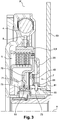
- the second example, presented at figure 2 differs in that the partition 53 forms a tight barrier between the springs 4 and the clutch 7.
- Such a partition 53 enables a wet clutch to be available without the wet clutch cooling oil polluting the environment of the springs.
- the partition 53 has an axial recess at the level of the clutch 5 making it possible to increase the space available for the clutch 5, in particular for the multi-disc assembly 22.
- the clutch 5 is therefore advantageously of the wet clutch type.
- the partition 53 can then define another supply network, comprising in particular a plurality of channels, for the passage of a cooling fluid of the clutch 5, such as gearbox oil. gears, intended to ensure the cooling and lubrication of the multidisc assembly.
- the channels can be evenly distributed around the X axis.
- the actuator 7 and the force transmission member 35 are also on the clutch side with respect to the partition 53.
- the intermediate element 6 bypasses the actuating member 7 and the force transmission member 35 from the inside to be fixed to the input disk holder 20 so that the element intermediate 6 does not interfere with the force transmission member 35.
- the intermediate element 6 comprises an arrangement different from that of the example of the figure 1 in that the web 8 extends radially as far as the hub portion 61 and in that the connection portion 9 is therefore not disposed between the web 8 and the hub portion 61.
- the connection portion 9 is disposed axially on the other side of the force transmission member 35 so that it is not necessary to provide an opening in the bearing surface on the assembly multidisk 22.
- the outer radial end 38 may be a continuous ring so that the bearing surface is continuous.
- the friction discs 23 are integral with the input disc holder 20 and they are radially outside the cylindrical skirt 27 and the plates are integral with the output disc holder 21 and they are radially inside the cylindrical skirt 28.
- the piston 43 has a “U” shape, in the plane of the figure.
- Such a piston makes it possible to act on the force transmission member radially outside the actuating chamber so that the actuator is extremely compact.
- the branches of the internal 65 and external 66 “U” radially frame the contour of the actuation chamber.
- the internal branch 65 is slidably mounted in the internal tube 46, the external branch 6 exerts an axial force oriented in the same direction as the force linked to the pressure on the internal branch 66.
- the rotating stop 49 is disposed radially outside the actuation chamber 48.
- the clutch 5 and its actuating member 7 are stacked radially towards the axis X.
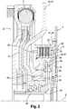
- the third example, presented at figure 3 differs from figure 1 by its mode of actuation.
- the actuator 7 also comprises the actuation chamber 48.
- the force transmission member 35 is moved by means of this actuation chamber which is delimited partly by said member 35.
- This actuator 7 is also called an actuator of the “piston” type.
- the actuating member 7 is integral in rotation with the intermediate element 6, via the hub portion 61.
- the actuating chamber 48 is sealed and filled with oil.
- the outline of the actuation chamber 48 is completed by an actuation chamber cover 69 integral in rotation with the force transmission member 35 by means of the hub portion 61 and fixed. axially so that the actuating chamber 48 and the oil it contains are in rotation.
- the actuating member 7 comprises a compensation chamber 70, sealed and filled with oil, delimited by the force transmission member 35 and by a cover balancing 71 integral in rotation with said transmission member 35.
- the balancing cover 71 is here defined by the connection portion 9 of the intermediate element 6.
- the force transmission member 35 forms a barrier between the two chambers 48, 70.
- the pressure chamber compensation 70 is intended to oppose the effects linked to the hydrodynamic oil pressure of the actuating chamber 48 on the transmission member 35.
- the force transmission member can thus be moved axially by varying the pressure d relative oil of the actuation 48 and compensation 70 chambers.
- the force transmission member 35, the actuating cover 69 and the balancing cover 71 are integral in rotation through the hub portion 61 of the intermediate element disposed radially inside and completing the contours of the two chambers 48, 70.
- the hub portion 61 can radially support the covers and the force transmission member.
- the hub portion 61 comprises slots 73 facing the bores, not shown, in at least one angular position of the actuating member 7.
- the bores can open radially.
- the holes are defined by the radial partition 53 for connecting the actuating chamber 48 and the compensation chamber 70, to the supply network.
- the intermediate element 6 is carried radially by means of two radial needle bearing bearings 55, mounted on the hub portion 61 and arranged axially on either side of the slots.
- the springs 4, the clutch 5 and the actuator 7 are stacked radially towards the axis X.
Landscapes
- Engineering & Computer Science (AREA)
- General Engineering & Computer Science (AREA)
- Mechanical Engineering (AREA)
- Chemical & Material Sciences (AREA)
- Combustion & Propulsion (AREA)
- Transportation (AREA)
- Physics & Mathematics (AREA)
- Acoustics & Sound (AREA)
- Aviation & Aerospace Engineering (AREA)
- Hydraulic Clutches, Magnetic Clutches, Fluid Clutches, And Fluid Joints (AREA)
- Mechanical Operated Clutches (AREA)
- Hybrid Electric Vehicles (AREA)
Claims (11)
- Vorrichtung (1) zur Drehmomentübertragung, insbesondere für ein Kraftfahrzeug, welche umfasst:- ein Drehmomenteingangselement (2), das mit einer Kurbelwelle einer Brennkraftmaschine drehgekoppelt werden kann,- ein Drehmomentausgangselement (3), das mit wenigstens einer Antriebswelle eines Getriebes und/oder mit einer rotierenden elektrischen Maschine drehgekoppelt werden kann, wobei das Drehmomenteingangselement in Bezug auf das Drehmomentausgangselement um eine Drehachse (X) schwenkbar ist,- wenigstens ein elastisches Rückholorgan (4), das der Drehung des Ausgangselements in Bezug auf das Eingangselement entgegenwirkt,- eine Kupplung (5), welche das Eingangs- und das Ausgangselement selektiv und durch Reibung koppelt,- ein Zwischenelement (6), das zwischen dem elastischen Rückholorgan und der Kupplung angeordnet ist, um das Drehmoment zu übertragen, und- ein Organ zur Betätigung (7) der Kupplung,wobei das elastische Rückholorgan, die Kupplung und das Betätigungsorgan radial aufeinanderfolgen, dadurch gekennzeichnet, dass:
die Kupplung (5) umfasst:- einen Eingangslamellenträger (20), der mit dem Zwischenelement drehfest verbunden ist,- einen Ausgangslamellenträger (21), der mit dem Ausgangselement drehfest verbunden ist,- eine Lamellenanordnung (22), die wenigstens eine Reibscheibe (23), die mit einem von dem Eingangs- und dem Ausgangslamellenträger drehfest verbunden ist, wenigstens zwei Platten (24), die jeweils beiderseits jeder Reibscheibe angeordnet sind und mit dem anderen von dem Eingangs- und dem Ausgangslamellenträger drehfest verbunden sind, und Reibbeläge (25), die zwischen den Platten und einer Reibscheibe angeordnet sind, umfasst, wobei die Kupplung (5) eine ausgekuppelte Position und eine eingekuppelte Position, in welcher die Platten und die Reibscheibe die Reibbeläge so festklemmen, dass ein Drehmoment zwischen dem Eingangslamellenträger (20) und dem Ausgangslamellenträger (21) übertragen wird, einnimmt,das Betätigungsorgan (7) einen ringförmigen Kolben (45), der axial gleitend außerhalb eines inneren Rohres (46) angebracht ist, wobei der Kolben und das Rohr eine Betätigungskammer (48) bilden, und einen drehenden Anschlag (49), der von dem Kolben getragen wird und mit dem Kraftübertragungsorgan zusammenwirkt, umfasst. - Vorrichtung (1) nach Anspruch 1, wobei die Kupplung (5) und das Betätigungsorgan (7) in Richtung zur Drehachse X hin radial gestapelt sind.
- Vorrichtung (1) nach einem der vorhergehenden Ansprüche, wobei das elastische Rückholorgan (4), die Kupplung (5) und das Betätigungsorgan (7) in Richtung zur Drehachse X hin radial gestapelt sind.
- Vorrichtung (1) nach Anspruch 1, welche ein Kraftübertragungsorgan (35) umfasst, das axial beweglich ist, um die Betätigungskraft des Betätigungsorgans (7) auf die Kupplung (5) zu übertragen, wobei ein Organ zum Halten in der ausgekuppelten Position (36) zwischen dem Zwischenelement (6) und dem Kraftübertragungsorgan (35) angeordnet ist.
- Vorrichtung (1) nach dem vorhergehenden Anspruch, wobei das Betätigungsorgan (7) eine Betätigungskammer (48) umfasst, wobei das Kraftübertragungsorgan mittels dieser Betätigungskammer verschoben wird, die teilweise von dem Kraftübertragungsorgan begrenzt wird.
- Vorrichtung (1) nach Anspruch 1, wobei der Kolben (45) eine U-Form aufweist.
- Vorrichtung (1) nach einem der Ansprüche 1 und 6, welche ein am Getriebe befestigbares Gehäuse (52) umfasst, das eine sich radial erstreckende Trennwand (53) umfasst, wobei die Trennwand wenigstens ein Versorgungsnetz der Betätigungskammer (48) definiert.
- Vorrichtung (1) nach dem vorhergehenden Anspruch, wobei die Trennwand (53) eine dichte Barriere zwischen dem elastischen Rückholorgan (4) und der Kupplung (5) bildet.
- Vorrichtung (1) nach einem der vorhergehenden Ansprüche, wobei das Zwischenelement (6) über wenigstens ein radiales Stützlager (55) von dem Gehäuse (52) radial gestützt wird.
- Vorrichtung (1) nach dem vorhergehenden Anspruch, wobei das radiale Stützlager (55) radial innerhalb des Betätigungsorgans (7) angeordnet ist.
- Vorrichtung (1) nach einem der vorhergehenden Ansprüche, wobei das Ausgangselement (3) einen Drehmomenteingang einer Doppelkupplung und/oder einer rotierenden elektrischen Maschine bildet.
Applications Claiming Priority (2)
| Application Number | Priority Date | Filing Date | Title |
|---|---|---|---|
| FR1660466A FR3058098B1 (fr) | 2016-10-27 | 2016-10-27 | Dispositif de transmission pour vehicule hybride |
| PCT/EP2017/077475 WO2018078029A1 (fr) | 2016-10-27 | 2017-10-26 | Dispositif de transmission pour vehicule hybride |
Publications (2)
| Publication Number | Publication Date |
|---|---|
| EP3532324A1 EP3532324A1 (de) | 2019-09-04 |
| EP3532324B1 true EP3532324B1 (de) | 2020-09-16 |
Family
ID=58314354
Family Applications (1)
| Application Number | Title | Priority Date | Filing Date |
|---|---|---|---|
| EP17787212.4A Active EP3532324B1 (de) | 2016-10-27 | 2017-10-26 | Getriebevorrichtung für hybridfahrzeug |
Country Status (4)
| Country | Link |
|---|---|
| EP (1) | EP3532324B1 (de) |
| CN (1) | CN109890639B (de) |
| FR (1) | FR3058098B1 (de) |
| WO (1) | WO2018078029A1 (de) |
Families Citing this family (8)
| Publication number | Priority date | Publication date | Assignee | Title |
|---|---|---|---|---|
| FR3073784B1 (fr) * | 2017-11-22 | 2020-08-28 | Valeo Embrayages | Dispositif de transmission pour vehicule hybride |
| DE112018005972T5 (de) * | 2017-11-22 | 2020-08-06 | Valeo Embrayages | Übertragungsvorrichtung für ein Hybridfahrzeug |
| FR3073787A1 (fr) * | 2017-11-22 | 2019-05-24 | Valeo Embrayages | Dispositif de transmission pour vehicule hybride |
| WO2019102099A2 (fr) * | 2017-11-22 | 2019-05-31 | Valeo Embrayages | Dispositif de transmission pour véhicule hybride |
| DE102018222514B4 (de) * | 2018-12-20 | 2022-08-04 | Audi Ag | Antriebseinrichtung |
| DE102020120523B4 (de) | 2020-08-04 | 2023-09-07 | Schaeffler Technologies AG & Co. KG | Trennkupplung mit einer Rotationsachse für einen Antriebsstrang |
| FR3117954B1 (fr) | 2020-12-17 | 2022-11-25 | Valeo Embrayages | Embrayage de coupure de couple |
| WO2022170464A1 (zh) * | 2021-02-09 | 2022-08-18 | 舍弗勒技术股份两合公司 | 扭转振动减振器和机动车 |
Citations (11)
| Publication number | Priority date | Publication date | Assignee | Title |
|---|---|---|---|---|
| JP2000304065A (ja) | 1999-08-24 | 2000-10-31 | Nsk Warner Kk | 発進クラッチ |
| FR2830589A1 (fr) | 2001-10-08 | 2003-04-11 | Valeo | Ensemble de transmission pour vehicule automobile comprenant deux embrayages et une machine electrique |
| JP2003262236A (ja) | 2002-03-07 | 2003-09-19 | Toyota Motor Corp | クラッチ装置 |
| US20050205379A1 (en) | 2004-03-22 | 2005-09-22 | Tryon Eric S | Torsional damper for electrically-variable transmission with lock-out clutch assembly |
| US20080121488A1 (en) | 2006-11-27 | 2008-05-29 | Tomoyuki Miyazaki | Starting clutch |
| US20080142331A1 (en) | 2006-12-15 | 2008-06-19 | Tomoyuki Miyazaki | Starting clutch |
| WO2010081453A2 (de) | 2009-01-19 | 2010-07-22 | Luk Lamellen Und Kupplungsbau Beteiligungs Kg | Hybridmodul für einen antriebsstrang eines fahrzeuges |
| DE102010051911A1 (de) | 2009-11-25 | 2011-06-01 | Schaeffler Technologies Gmbh & Co. Kg | Mehrfachkupplungsvorrichtung, Bauteil, Baugruppen und Verfahren zur Montage |
| DE102010004711A1 (de) | 2010-01-11 | 2011-07-14 | GETRAG Getriebe- und Zahnradfabrik Hermann Hagenmeyer GmbH & Cie KG, 74199 | Hybrid-Antriebsstrang und Verfahren zum Ansteuern desselben |
| DE102012220443A1 (de) | 2011-11-30 | 2013-06-06 | Schaeffler Technologies AG & Co. KG | Nasse Doppelkupplung |
| FR3015380A1 (fr) | 2013-12-19 | 2015-06-26 | Valeo Embrayages | Ensemble de transmission pour vehicule hybride equipe d'un amortisseur pendulaire |
Family Cites Families (5)
| Publication number | Priority date | Publication date | Assignee | Title |
|---|---|---|---|---|
| EP1548313B2 (de) * | 2003-12-23 | 2016-09-28 | Schaeffler Technologies AG & Co. KG | Drehmomentübertragungseinrichtung |
| DE112005002200B4 (de) * | 2004-11-19 | 2011-04-28 | Aisin AW Co., Ltd., Anjo-shi | Hybridfahrzeugantriebseinheit |
| US7926635B2 (en) * | 2006-12-27 | 2011-04-19 | Schaeffler Technologies Gmbh & Co. Kg | Piston assembly and a force transfer device, particularly a force transfer device with a piston assembly |
| US8434607B2 (en) * | 2010-02-23 | 2013-05-07 | GM Global Technology Operations LLC | Compact torque transmitting assembly |
| US9157495B2 (en) * | 2013-10-24 | 2015-10-13 | Ford Global Technologies, Llc | Torque converter having integrated flex plate for hybrid electric vehicle |
-
2016
- 2016-10-27 FR FR1660466A patent/FR3058098B1/fr active Active
-
2017
- 2017-10-26 EP EP17787212.4A patent/EP3532324B1/de active Active
- 2017-10-26 CN CN201780067156.3A patent/CN109890639B/zh active Active
- 2017-10-26 WO PCT/EP2017/077475 patent/WO2018078029A1/fr unknown
Patent Citations (11)
| Publication number | Priority date | Publication date | Assignee | Title |
|---|---|---|---|---|
| JP2000304065A (ja) | 1999-08-24 | 2000-10-31 | Nsk Warner Kk | 発進クラッチ |
| FR2830589A1 (fr) | 2001-10-08 | 2003-04-11 | Valeo | Ensemble de transmission pour vehicule automobile comprenant deux embrayages et une machine electrique |
| JP2003262236A (ja) | 2002-03-07 | 2003-09-19 | Toyota Motor Corp | クラッチ装置 |
| US20050205379A1 (en) | 2004-03-22 | 2005-09-22 | Tryon Eric S | Torsional damper for electrically-variable transmission with lock-out clutch assembly |
| US20080121488A1 (en) | 2006-11-27 | 2008-05-29 | Tomoyuki Miyazaki | Starting clutch |
| US20080142331A1 (en) | 2006-12-15 | 2008-06-19 | Tomoyuki Miyazaki | Starting clutch |
| WO2010081453A2 (de) | 2009-01-19 | 2010-07-22 | Luk Lamellen Und Kupplungsbau Beteiligungs Kg | Hybridmodul für einen antriebsstrang eines fahrzeuges |
| DE102010051911A1 (de) | 2009-11-25 | 2011-06-01 | Schaeffler Technologies Gmbh & Co. Kg | Mehrfachkupplungsvorrichtung, Bauteil, Baugruppen und Verfahren zur Montage |
| DE102010004711A1 (de) | 2010-01-11 | 2011-07-14 | GETRAG Getriebe- und Zahnradfabrik Hermann Hagenmeyer GmbH & Cie KG, 74199 | Hybrid-Antriebsstrang und Verfahren zum Ansteuern desselben |
| DE102012220443A1 (de) | 2011-11-30 | 2013-06-06 | Schaeffler Technologies AG & Co. KG | Nasse Doppelkupplung |
| FR3015380A1 (fr) | 2013-12-19 | 2015-06-26 | Valeo Embrayages | Ensemble de transmission pour vehicule hybride equipe d'un amortisseur pendulaire |
Also Published As
| Publication number | Publication date |
|---|---|
| CN109890639A (zh) | 2019-06-14 |
| WO2018078029A1 (fr) | 2018-05-03 |
| FR3058098A1 (fr) | 2018-05-04 |
| CN109890639B (zh) | 2022-10-21 |
| EP3532324A1 (de) | 2019-09-04 |
| FR3058098B1 (fr) | 2024-01-19 |
Similar Documents
| Publication | Publication Date | Title |
|---|---|---|
| EP3532324B1 (de) | Getriebevorrichtung für hybridfahrzeug | |
| FR3069201B1 (fr) | Dispositif de transmission pour vehicule hybride | |
| FR3069296A1 (fr) | Dispositif de transmission pour vehicule hybride | |
| FR3090774A1 (fr) | Dispositif de transmission pour véhicule automobile | |
| EP3757414A1 (de) | Vorrichtung zur drehmomentübertragung | |
| EP3899300A1 (de) | Getriebevorrichtung für ein kraftfahrzeug | |
| WO2017149161A1 (fr) | Systeme de transmission de couple | |
| FR3015605A1 (fr) | Ensemble de transmission equipe d'un amortisseur pendulaire s'etendant radialement a l'exterieur d'un dispositif d'embrayage | |
| EP3710298A1 (de) | Getriebevorrichtung für hybridfahrzeug | |
| WO2018002500A1 (fr) | Dispositif de transmission de couple, notamment pour véhicule automobile | |
| WO2019211244A1 (fr) | Dispositif de transmission pour vehicule automobile | |
| WO2019102099A2 (fr) | Dispositif de transmission pour véhicule hybride | |
| FR3079572A1 (fr) | Dispositif de transmission pour vehicule automobile | |
| FR3079455A1 (fr) | Dispositif de transmission pour vehicule hybride | |
| FR3069199A1 (fr) | Dispositif de transmission pour vehicule hybride | |
| FR3073784A1 (fr) | Dispositif de transmission pour vehicule hybride | |
| FR3069200A1 (fr) | Dispositif de transmission pour vehicule hybride | |
| FR3073788A1 (fr) | Dispositif de transmission pour vehicule hybride | |
| WO2018104139A1 (fr) | Dispositif d'amortissement de torsion | |
| FR3084024A1 (fr) | Dispositif de transmission pour vehicule hybride | |
| FR3078377A1 (fr) | Dispositif de transmission pour vehicule hybride | |
| FR3080896A1 (fr) | Dispositif de transmission pour vehicule automobile | |
| FR3073914A1 (fr) | Dispositif de transmission pour vehicule hybride | |
| FR3078376A1 (fr) | Dispositif de transmission pour vehicule hybride | |
| FR3080898A1 (fr) | Dispositif de transmission pour vehicule automobile |
Legal Events
| Date | Code | Title | Description |
|---|---|---|---|
| STAA | Information on the status of an ep patent application or granted ep patent |
Free format text: STATUS: UNKNOWN |
|
| STAA | Information on the status of an ep patent application or granted ep patent |
Free format text: STATUS: THE INTERNATIONAL PUBLICATION HAS BEEN MADE |
|
| PUAI | Public reference made under article 153(3) epc to a published international application that has entered the european phase |
Free format text: ORIGINAL CODE: 0009012 |
|
| STAA | Information on the status of an ep patent application or granted ep patent |
Free format text: STATUS: REQUEST FOR EXAMINATION WAS MADE |
|
| 17P | Request for examination filed |
Effective date: 20190327 |
|
| AK | Designated contracting states |
Kind code of ref document: A1 Designated state(s): AL AT BE BG CH CY CZ DE DK EE ES FI FR GB GR HR HU IE IS IT LI LT LU LV MC MK MT NL NO PL PT RO RS SE SI SK SM TR |
|
| AX | Request for extension of the european patent |
Extension state: BA ME |
|
| DAV | Request for validation of the european patent (deleted) | ||
| DAX | Request for extension of the european patent (deleted) | ||
| GRAP | Despatch of communication of intention to grant a patent |
Free format text: ORIGINAL CODE: EPIDOSNIGR1 |
|
| STAA | Information on the status of an ep patent application or granted ep patent |
Free format text: STATUS: GRANT OF PATENT IS INTENDED |
|
| INTG | Intention to grant announced |
Effective date: 20200508 |
|
| RIN1 | Information on inventor provided before grant (corrected) |
Inventor name: DOLE, ARNAUD Inventor name: THIBAUT, FRANCOIS Inventor name: BACQ, VINCENT Inventor name: COMMEINE, EMMANUEL Inventor name: LEBAS, GILLES |
|
| GRAS | Grant fee paid |
Free format text: ORIGINAL CODE: EPIDOSNIGR3 |
|
| GRAA | (expected) grant |
Free format text: ORIGINAL CODE: 0009210 |
|
| STAA | Information on the status of an ep patent application or granted ep patent |
Free format text: STATUS: THE PATENT HAS BEEN GRANTED |
|
| AK | Designated contracting states |
Kind code of ref document: B1 Designated state(s): AL AT BE BG CH CY CZ DE DK EE ES FI FR GB GR HR HU IE IS IT LI LT LU LV MC MK MT NL NO PL PT RO RS SE SI SK SM TR |
|
| REG | Reference to a national code |
Ref country code: GB Ref legal event code: FG4D Free format text: NOT ENGLISH |
|
| REG | Reference to a national code |
Ref country code: CH Ref legal event code: EP |
|
| REG | Reference to a national code |
Ref country code: DE Ref legal event code: R096 Ref document number: 602017023839 Country of ref document: DE |
|
| REG | Reference to a national code |
Ref country code: IE Ref legal event code: FG4D Free format text: LANGUAGE OF EP DOCUMENT: FRENCH |
|
| REG | Reference to a national code |
Ref country code: AT Ref legal event code: REF Ref document number: 1313851 Country of ref document: AT Kind code of ref document: T Effective date: 20201015 |
|
| PG25 | Lapsed in a contracting state [announced via postgrant information from national office to epo] |
Ref country code: FI Free format text: LAPSE BECAUSE OF FAILURE TO SUBMIT A TRANSLATION OF THE DESCRIPTION OR TO PAY THE FEE WITHIN THE PRESCRIBED TIME-LIMIT Effective date: 20200916 Ref country code: HR Free format text: LAPSE BECAUSE OF FAILURE TO SUBMIT A TRANSLATION OF THE DESCRIPTION OR TO PAY THE FEE WITHIN THE PRESCRIBED TIME-LIMIT Effective date: 20200916 Ref country code: SE Free format text: LAPSE BECAUSE OF FAILURE TO SUBMIT A TRANSLATION OF THE DESCRIPTION OR TO PAY THE FEE WITHIN THE PRESCRIBED TIME-LIMIT Effective date: 20200916 Ref country code: GR Free format text: LAPSE BECAUSE OF FAILURE TO SUBMIT A TRANSLATION OF THE DESCRIPTION OR TO PAY THE FEE WITHIN THE PRESCRIBED TIME-LIMIT Effective date: 20201217 Ref country code: NO Free format text: LAPSE BECAUSE OF FAILURE TO SUBMIT A TRANSLATION OF THE DESCRIPTION OR TO PAY THE FEE WITHIN THE PRESCRIBED TIME-LIMIT Effective date: 20201216 Ref country code: BG Free format text: LAPSE BECAUSE OF FAILURE TO SUBMIT A TRANSLATION OF THE DESCRIPTION OR TO PAY THE FEE WITHIN THE PRESCRIBED TIME-LIMIT Effective date: 20201216 |
|
| REG | Reference to a national code |
Ref country code: AT Ref legal event code: MK05 Ref document number: 1313851 Country of ref document: AT Kind code of ref document: T Effective date: 20200916 |
|
| REG | Reference to a national code |
Ref country code: NL Ref legal event code: MP Effective date: 20200916 |
|
| PG25 | Lapsed in a contracting state [announced via postgrant information from national office to epo] |
Ref country code: LV Free format text: LAPSE BECAUSE OF FAILURE TO SUBMIT A TRANSLATION OF THE DESCRIPTION OR TO PAY THE FEE WITHIN THE PRESCRIBED TIME-LIMIT Effective date: 20200916 Ref country code: RS Free format text: LAPSE BECAUSE OF FAILURE TO SUBMIT A TRANSLATION OF THE DESCRIPTION OR TO PAY THE FEE WITHIN THE PRESCRIBED TIME-LIMIT Effective date: 20200916 |
|
| REG | Reference to a national code |
Ref country code: LT Ref legal event code: MG4D |
|
| PG25 | Lapsed in a contracting state [announced via postgrant information from national office to epo] |
Ref country code: SM Free format text: LAPSE BECAUSE OF FAILURE TO SUBMIT A TRANSLATION OF THE DESCRIPTION OR TO PAY THE FEE WITHIN THE PRESCRIBED TIME-LIMIT Effective date: 20200916 Ref country code: LT Free format text: LAPSE BECAUSE OF FAILURE TO SUBMIT A TRANSLATION OF THE DESCRIPTION OR TO PAY THE FEE WITHIN THE PRESCRIBED TIME-LIMIT Effective date: 20200916 Ref country code: CZ Free format text: LAPSE BECAUSE OF FAILURE TO SUBMIT A TRANSLATION OF THE DESCRIPTION OR TO PAY THE FEE WITHIN THE PRESCRIBED TIME-LIMIT Effective date: 20200916 Ref country code: PT Free format text: LAPSE BECAUSE OF FAILURE TO SUBMIT A TRANSLATION OF THE DESCRIPTION OR TO PAY THE FEE WITHIN THE PRESCRIBED TIME-LIMIT Effective date: 20210118 Ref country code: RO Free format text: LAPSE BECAUSE OF FAILURE TO SUBMIT A TRANSLATION OF THE DESCRIPTION OR TO PAY THE FEE WITHIN THE PRESCRIBED TIME-LIMIT Effective date: 20200916 Ref country code: EE Free format text: LAPSE BECAUSE OF FAILURE TO SUBMIT A TRANSLATION OF THE DESCRIPTION OR TO PAY THE FEE WITHIN THE PRESCRIBED TIME-LIMIT Effective date: 20200916 |
|
| PG25 | Lapsed in a contracting state [announced via postgrant information from national office to epo] |
Ref country code: ES Free format text: LAPSE BECAUSE OF FAILURE TO SUBMIT A TRANSLATION OF THE DESCRIPTION OR TO PAY THE FEE WITHIN THE PRESCRIBED TIME-LIMIT Effective date: 20200916 Ref country code: AL Free format text: LAPSE BECAUSE OF FAILURE TO SUBMIT A TRANSLATION OF THE DESCRIPTION OR TO PAY THE FEE WITHIN THE PRESCRIBED TIME-LIMIT Effective date: 20200916 Ref country code: AT Free format text: LAPSE BECAUSE OF FAILURE TO SUBMIT A TRANSLATION OF THE DESCRIPTION OR TO PAY THE FEE WITHIN THE PRESCRIBED TIME-LIMIT Effective date: 20200916 Ref country code: PL Free format text: LAPSE BECAUSE OF FAILURE TO SUBMIT A TRANSLATION OF THE DESCRIPTION OR TO PAY THE FEE WITHIN THE PRESCRIBED TIME-LIMIT Effective date: 20200916 Ref country code: IS Free format text: LAPSE BECAUSE OF FAILURE TO SUBMIT A TRANSLATION OF THE DESCRIPTION OR TO PAY THE FEE WITHIN THE PRESCRIBED TIME-LIMIT Effective date: 20210116 |
|
| REG | Reference to a national code |
Ref country code: CH Ref legal event code: PL |
|
| REG | Reference to a national code |
Ref country code: DE Ref legal event code: R026 Ref document number: 602017023839 Country of ref document: DE |
|
| PLBI | Opposition filed |
Free format text: ORIGINAL CODE: 0009260 |
|
| PG25 | Lapsed in a contracting state [announced via postgrant information from national office to epo] |
Ref country code: MC Free format text: LAPSE BECAUSE OF FAILURE TO SUBMIT A TRANSLATION OF THE DESCRIPTION OR TO PAY THE FEE WITHIN THE PRESCRIBED TIME-LIMIT Effective date: 20200916 Ref country code: LU Free format text: LAPSE BECAUSE OF NON-PAYMENT OF DUE FEES Effective date: 20201026 Ref country code: SK Free format text: LAPSE BECAUSE OF FAILURE TO SUBMIT A TRANSLATION OF THE DESCRIPTION OR TO PAY THE FEE WITHIN THE PRESCRIBED TIME-LIMIT Effective date: 20200916 |
|
| REG | Reference to a national code |
Ref country code: BE Ref legal event code: MM Effective date: 20201031 |
|
| 26 | Opposition filed |
Opponent name: SCHAEFFLER TECHNOLOGIES AG & CO. KG Effective date: 20210611 |
|
| PLAX | Notice of opposition and request to file observation + time limit sent |
Free format text: ORIGINAL CODE: EPIDOSNOBS2 |
|
| PG25 | Lapsed in a contracting state [announced via postgrant information from national office to epo] |
Ref country code: BE Free format text: LAPSE BECAUSE OF NON-PAYMENT OF DUE FEES Effective date: 20201031 Ref country code: CH Free format text: LAPSE BECAUSE OF NON-PAYMENT OF DUE FEES Effective date: 20201031 Ref country code: SI Free format text: LAPSE BECAUSE OF FAILURE TO SUBMIT A TRANSLATION OF THE DESCRIPTION OR TO PAY THE FEE WITHIN THE PRESCRIBED TIME-LIMIT Effective date: 20200916 Ref country code: DK Free format text: LAPSE BECAUSE OF FAILURE TO SUBMIT A TRANSLATION OF THE DESCRIPTION OR TO PAY THE FEE WITHIN THE PRESCRIBED TIME-LIMIT Effective date: 20200916 Ref country code: LI Free format text: LAPSE BECAUSE OF NON-PAYMENT OF DUE FEES Effective date: 20201031 |
|
| PG25 | Lapsed in a contracting state [announced via postgrant information from national office to epo] |
Ref country code: IT Free format text: LAPSE BECAUSE OF FAILURE TO SUBMIT A TRANSLATION OF THE DESCRIPTION OR TO PAY THE FEE WITHIN THE PRESCRIBED TIME-LIMIT Effective date: 20200916 Ref country code: IE Free format text: LAPSE BECAUSE OF NON-PAYMENT OF DUE FEES Effective date: 20201026 |
|
| PLBB | Reply of patent proprietor to notice(s) of opposition received |
Free format text: ORIGINAL CODE: EPIDOSNOBS3 |
|
| PG25 | Lapsed in a contracting state [announced via postgrant information from national office to epo] |
Ref country code: TR Free format text: LAPSE BECAUSE OF FAILURE TO SUBMIT A TRANSLATION OF THE DESCRIPTION OR TO PAY THE FEE WITHIN THE PRESCRIBED TIME-LIMIT Effective date: 20200916 Ref country code: MT Free format text: LAPSE BECAUSE OF FAILURE TO SUBMIT A TRANSLATION OF THE DESCRIPTION OR TO PAY THE FEE WITHIN THE PRESCRIBED TIME-LIMIT Effective date: 20200916 Ref country code: CY Free format text: LAPSE BECAUSE OF FAILURE TO SUBMIT A TRANSLATION OF THE DESCRIPTION OR TO PAY THE FEE WITHIN THE PRESCRIBED TIME-LIMIT Effective date: 20200916 |
|
| GBPC | Gb: european patent ceased through non-payment of renewal fee |
Effective date: 20211026 |
|
| PG25 | Lapsed in a contracting state [announced via postgrant information from national office to epo] |
Ref country code: MK Free format text: LAPSE BECAUSE OF FAILURE TO SUBMIT A TRANSLATION OF THE DESCRIPTION OR TO PAY THE FEE WITHIN THE PRESCRIBED TIME-LIMIT Effective date: 20200916 |
|
| PG25 | Lapsed in a contracting state [announced via postgrant information from national office to epo] |
Ref country code: GB Free format text: LAPSE BECAUSE OF NON-PAYMENT OF DUE FEES Effective date: 20211026 |
|
| APBM | Appeal reference recorded |
Free format text: ORIGINAL CODE: EPIDOSNREFNO |
|
| APBP | Date of receipt of notice of appeal recorded |
Free format text: ORIGINAL CODE: EPIDOSNNOA2O |
|
| PLAB | Opposition data, opponent's data or that of the opponent's representative modified |
Free format text: ORIGINAL CODE: 0009299OPPO |
|
| APAH | Appeal reference modified |
Free format text: ORIGINAL CODE: EPIDOSCREFNO |
|
| APBM | Appeal reference recorded |
Free format text: ORIGINAL CODE: EPIDOSNREFNO |
|
| APBP | Date of receipt of notice of appeal recorded |
Free format text: ORIGINAL CODE: EPIDOSNNOA2O |
|
| R26 | Opposition filed (corrected) |
Opponent name: SCHAEFFLER TECHNOLOGIES AG & CO. KG Effective date: 20210611 |
|
| APBQ | Date of receipt of statement of grounds of appeal recorded |
Free format text: ORIGINAL CODE: EPIDOSNNOA3O |
|
| PG25 | Lapsed in a contracting state [announced via postgrant information from national office to epo] |
Ref country code: NL Free format text: LAPSE BECAUSE OF NON-PAYMENT OF DUE FEES Effective date: 20200923 |
|
| P01 | Opt-out of the competence of the unified patent court (upc) registered |
Effective date: 20230528 |
|
| APAH | Appeal reference modified |
Free format text: ORIGINAL CODE: EPIDOSCREFNO |
|
| PGFP | Annual fee paid to national office [announced via postgrant information from national office to epo] |
Ref country code: FR Payment date: 20231023 Year of fee payment: 7 Ref country code: DE Payment date: 20231011 Year of fee payment: 7 |