EP3532004B1 - Modulares therapeutisches vibrationssystem für rehabilitation - Google Patents
Modulares therapeutisches vibrationssystem für rehabilitation Download PDFInfo
- Publication number
- EP3532004B1 EP3532004B1 EP17864579.2A EP17864579A EP3532004B1 EP 3532004 B1 EP3532004 B1 EP 3532004B1 EP 17864579 A EP17864579 A EP 17864579A EP 3532004 B1 EP3532004 B1 EP 3532004B1
- Authority
- EP
- European Patent Office
- Prior art keywords
- user
- foot plate
- foot
- force
- support
- Prior art date
- Legal status (The legal status is an assumption and is not a legal conclusion. Google has not performed a legal analysis and makes no representation as to the accuracy of the status listed.)
- Active
Links
Images


Classifications
-
- A—HUMAN NECESSITIES
- A61—MEDICAL OR VETERINARY SCIENCE; HYGIENE
- A61H—PHYSICAL THERAPY APPARATUS, e.g. DEVICES FOR LOCATING OR STIMULATING REFLEX POINTS IN THE BODY; ARTIFICIAL RESPIRATION; MASSAGE; BATHING DEVICES FOR SPECIAL THERAPEUTIC OR HYGIENIC PURPOSES OR SPECIFIC PARTS OF THE BODY
- A61H1/00—Apparatus for passive exercising; Vibrating apparatus; Chiropractic devices, e.g. body impacting devices, external devices for briefly extending or aligning unbroken bones
- A61H1/005—Moveable platforms, e.g. vibrating or oscillating platforms for standing, sitting, laying or leaning
-
- A—HUMAN NECESSITIES
- A61—MEDICAL OR VETERINARY SCIENCE; HYGIENE
- A61H—PHYSICAL THERAPY APPARATUS, e.g. DEVICES FOR LOCATING OR STIMULATING REFLEX POINTS IN THE BODY; ARTIFICIAL RESPIRATION; MASSAGE; BATHING DEVICES FOR SPECIAL THERAPEUTIC OR HYGIENIC PURPOSES OR SPECIFIC PARTS OF THE BODY
- A61H23/00—Percussion or vibration massage, e.g. using supersonic vibration; Suction-vibration massage; Massage with moving diaphragms
- A61H23/02—Percussion or vibration massage, e.g. using supersonic vibration; Suction-vibration massage; Massage with moving diaphragms with electric or magnetic drive
-
- A—HUMAN NECESSITIES
- A61—MEDICAL OR VETERINARY SCIENCE; HYGIENE
- A61H—PHYSICAL THERAPY APPARATUS, e.g. DEVICES FOR LOCATING OR STIMULATING REFLEX POINTS IN THE BODY; ARTIFICIAL RESPIRATION; MASSAGE; BATHING DEVICES FOR SPECIAL THERAPEUTIC OR HYGIENIC PURPOSES OR SPECIFIC PARTS OF THE BODY
- A61H1/00—Apparatus for passive exercising; Vibrating apparatus; Chiropractic devices, e.g. body impacting devices, external devices for briefly extending or aligning unbroken bones
- A61H1/02—Stretching or bending or torsioning apparatus for exercising
- A61H1/0237—Stretching or bending or torsioning apparatus for exercising for the lower limbs
-
- A—HUMAN NECESSITIES
- A61—MEDICAL OR VETERINARY SCIENCE; HYGIENE
- A61H—PHYSICAL THERAPY APPARATUS, e.g. DEVICES FOR LOCATING OR STIMULATING REFLEX POINTS IN THE BODY; ARTIFICIAL RESPIRATION; MASSAGE; BATHING DEVICES FOR SPECIAL THERAPEUTIC OR HYGIENIC PURPOSES OR SPECIFIC PARTS OF THE BODY
- A61H23/00—Percussion or vibration massage, e.g. using supersonic vibration; Suction-vibration massage; Massage with moving diaphragms
- A61H23/02—Percussion or vibration massage, e.g. using supersonic vibration; Suction-vibration massage; Massage with moving diaphragms with electric or magnetic drive
- A61H23/0254—Percussion or vibration massage, e.g. using supersonic vibration; Suction-vibration massage; Massage with moving diaphragms with electric or magnetic drive with rotary motor
- A61H23/0263—Percussion or vibration massage, e.g. using supersonic vibration; Suction-vibration massage; Massage with moving diaphragms with electric or magnetic drive with rotary motor using rotating unbalanced masses
-
- A—HUMAN NECESSITIES
- A63—SPORTS; GAMES; AMUSEMENTS
- A63B—APPARATUS FOR PHYSICAL TRAINING, GYMNASTICS, SWIMMING, CLIMBING, OR FENCING; BALL GAMES; TRAINING EQUIPMENT
- A63B21/00—Exercising apparatus for developing or strengthening the muscles or joints of the body by working against a counterforce, with or without measuring devices
- A63B21/00196—Exercising apparatus for developing or strengthening the muscles or joints of the body by working against a counterforce, with or without measuring devices using pulsed counterforce, e.g. vibrating resistance means
-
- A—HUMAN NECESSITIES
- A61—MEDICAL OR VETERINARY SCIENCE; HYGIENE
- A61H—PHYSICAL THERAPY APPARATUS, e.g. DEVICES FOR LOCATING OR STIMULATING REFLEX POINTS IN THE BODY; ARTIFICIAL RESPIRATION; MASSAGE; BATHING DEVICES FOR SPECIAL THERAPEUTIC OR HYGIENIC PURPOSES OR SPECIFIC PARTS OF THE BODY
- A61H2201/00—Characteristics of apparatus not provided for in the preceding codes
- A61H2201/16—Physical interface with patient
- A61H2201/1602—Physical interface with patient kind of interface, e.g. head rest, knee support or lumbar support
- A61H2201/164—Feet or leg, e.g. pedal
-
- A—HUMAN NECESSITIES
- A61—MEDICAL OR VETERINARY SCIENCE; HYGIENE
- A61H—PHYSICAL THERAPY APPARATUS, e.g. DEVICES FOR LOCATING OR STIMULATING REFLEX POINTS IN THE BODY; ARTIFICIAL RESPIRATION; MASSAGE; BATHING DEVICES FOR SPECIAL THERAPEUTIC OR HYGIENIC PURPOSES OR SPECIFIC PARTS OF THE BODY
- A61H2201/00—Characteristics of apparatus not provided for in the preceding codes
- A61H2201/16—Physical interface with patient
- A61H2201/1657—Movement of interface, i.e. force application means
- A61H2201/1671—Movement of interface, i.e. force application means rotational
-
- A—HUMAN NECESSITIES
- A61—MEDICAL OR VETERINARY SCIENCE; HYGIENE
- A61H—PHYSICAL THERAPY APPARATUS, e.g. DEVICES FOR LOCATING OR STIMULATING REFLEX POINTS IN THE BODY; ARTIFICIAL RESPIRATION; MASSAGE; BATHING DEVICES FOR SPECIAL THERAPEUTIC OR HYGIENIC PURPOSES OR SPECIFIC PARTS OF THE BODY
- A61H2201/00—Characteristics of apparatus not provided for in the preceding codes
- A61H2201/50—Control means thereof
- A61H2201/5058—Sensors or detectors
-
- A—HUMAN NECESSITIES
- A61—MEDICAL OR VETERINARY SCIENCE; HYGIENE
- A61H—PHYSICAL THERAPY APPARATUS, e.g. DEVICES FOR LOCATING OR STIMULATING REFLEX POINTS IN THE BODY; ARTIFICIAL RESPIRATION; MASSAGE; BATHING DEVICES FOR SPECIAL THERAPEUTIC OR HYGIENIC PURPOSES OR SPECIFIC PARTS OF THE BODY
- A61H2201/00—Characteristics of apparatus not provided for in the preceding codes
- A61H2201/50—Control means thereof
- A61H2201/5058—Sensors or detectors
- A61H2201/5061—Force sensors
-
- A—HUMAN NECESSITIES
- A61—MEDICAL OR VETERINARY SCIENCE; HYGIENE
- A61H—PHYSICAL THERAPY APPARATUS, e.g. DEVICES FOR LOCATING OR STIMULATING REFLEX POINTS IN THE BODY; ARTIFICIAL RESPIRATION; MASSAGE; BATHING DEVICES FOR SPECIAL THERAPEUTIC OR HYGIENIC PURPOSES OR SPECIFIC PARTS OF THE BODY
- A61H2201/00—Characteristics of apparatus not provided for in the preceding codes
- A61H2201/50—Control means thereof
- A61H2201/5058—Sensors or detectors
- A61H2201/5084—Acceleration sensors
-
- A—HUMAN NECESSITIES
- A61—MEDICAL OR VETERINARY SCIENCE; HYGIENE
- A61H—PHYSICAL THERAPY APPARATUS, e.g. DEVICES FOR LOCATING OR STIMULATING REFLEX POINTS IN THE BODY; ARTIFICIAL RESPIRATION; MASSAGE; BATHING DEVICES FOR SPECIAL THERAPEUTIC OR HYGIENIC PURPOSES OR SPECIFIC PARTS OF THE BODY
- A61H2201/00—Characteristics of apparatus not provided for in the preceding codes
- A61H2201/50—Control means thereof
- A61H2201/5097—Control means thereof wireless
-
- A—HUMAN NECESSITIES
- A61—MEDICAL OR VETERINARY SCIENCE; HYGIENE
- A61H—PHYSICAL THERAPY APPARATUS, e.g. DEVICES FOR LOCATING OR STIMULATING REFLEX POINTS IN THE BODY; ARTIFICIAL RESPIRATION; MASSAGE; BATHING DEVICES FOR SPECIAL THERAPEUTIC OR HYGIENIC PURPOSES OR SPECIFIC PARTS OF THE BODY
- A61H2203/00—Additional characteristics concerning the patient
- A61H2203/04—Position of the patient
- A61H2203/0425—Sitting on the buttocks
- A61H2203/0431—Sitting on the buttocks in 90°/90°-position, like on a chair
-
- A—HUMAN NECESSITIES
- A61—MEDICAL OR VETERINARY SCIENCE; HYGIENE
- A61H—PHYSICAL THERAPY APPARATUS, e.g. DEVICES FOR LOCATING OR STIMULATING REFLEX POINTS IN THE BODY; ARTIFICIAL RESPIRATION; MASSAGE; BATHING DEVICES FOR SPECIAL THERAPEUTIC OR HYGIENIC PURPOSES OR SPECIFIC PARTS OF THE BODY
- A61H2203/00—Additional characteristics concerning the patient
- A61H2203/04—Position of the patient
- A61H2203/0425—Sitting on the buttocks
- A61H2203/0437—Sitting on the buttocks with stretched legs, like in a bed
-
- A—HUMAN NECESSITIES
- A61—MEDICAL OR VETERINARY SCIENCE; HYGIENE
- A61H—PHYSICAL THERAPY APPARATUS, e.g. DEVICES FOR LOCATING OR STIMULATING REFLEX POINTS IN THE BODY; ARTIFICIAL RESPIRATION; MASSAGE; BATHING DEVICES FOR SPECIAL THERAPEUTIC OR HYGIENIC PURPOSES OR SPECIFIC PARTS OF THE BODY
- A61H2230/00—Measuring physical parameters of the user
- A61H2230/08—Other bio-electrical signals
-
- A—HUMAN NECESSITIES
- A61—MEDICAL OR VETERINARY SCIENCE; HYGIENE
- A61H—PHYSICAL THERAPY APPARATUS, e.g. DEVICES FOR LOCATING OR STIMULATING REFLEX POINTS IN THE BODY; ARTIFICIAL RESPIRATION; MASSAGE; BATHING DEVICES FOR SPECIAL THERAPEUTIC OR HYGIENIC PURPOSES OR SPECIFIC PARTS OF THE BODY
- A61H2230/00—Measuring physical parameters of the user
- A61H2230/65—Impedance, e.g. skin conductivity; capacitance, e.g. galvanic skin response [GSR]
-
- A—HUMAN NECESSITIES
- A63—SPORTS; GAMES; AMUSEMENTS
- A63B—APPARATUS FOR PHYSICAL TRAINING, GYMNASTICS, SWIMMING, CLIMBING, OR FENCING; BALL GAMES; TRAINING EQUIPMENT
- A63B21/00—Exercising apparatus for developing or strengthening the muscles or joints of the body by working against a counterforce, with or without measuring devices
- A63B21/02—Exercising apparatus for developing or strengthening the muscles or joints of the body by working against a counterforce, with or without measuring devices using resilient force-resisters
- A63B21/04—Exercising apparatus for developing or strengthening the muscles or joints of the body by working against a counterforce, with or without measuring devices using resilient force-resisters attached to static foundation, e.g. a user
- A63B21/0442—Anchored at one end only, the other end being manipulated by the user
-
- A—HUMAN NECESSITIES
- A63—SPORTS; GAMES; AMUSEMENTS
- A63B—APPARATUS FOR PHYSICAL TRAINING, GYMNASTICS, SWIMMING, CLIMBING, OR FENCING; BALL GAMES; TRAINING EQUIPMENT
- A63B21/00—Exercising apparatus for developing or strengthening the muscles or joints of the body by working against a counterforce, with or without measuring devices
- A63B21/02—Exercising apparatus for developing or strengthening the muscles or joints of the body by working against a counterforce, with or without measuring devices using resilient force-resisters
- A63B21/055—Exercising apparatus for developing or strengthening the muscles or joints of the body by working against a counterforce, with or without measuring devices using resilient force-resisters extension element type
- A63B21/0552—Elastic ropes or bands
-
- A—HUMAN NECESSITIES
- A63—SPORTS; GAMES; AMUSEMENTS
- A63B—APPARATUS FOR PHYSICAL TRAINING, GYMNASTICS, SWIMMING, CLIMBING, OR FENCING; BALL GAMES; TRAINING EQUIPMENT
- A63B2208/00—Characteristics or parameters related to the user or player
- A63B2208/02—Characteristics or parameters related to the user or player posture
- A63B2208/0228—Sitting on the buttocks
- A63B2208/0238—Sitting on the buttocks with stretched legs, like on a bed
-
- A—HUMAN NECESSITIES
- A63—SPORTS; GAMES; AMUSEMENTS
- A63B—APPARATUS FOR PHYSICAL TRAINING, GYMNASTICS, SWIMMING, CLIMBING, OR FENCING; BALL GAMES; TRAINING EQUIPMENT
- A63B2220/00—Measuring of physical parameters relating to sporting activity
- A63B2220/18—Inclination, slope or curvature
-
- A—HUMAN NECESSITIES
- A63—SPORTS; GAMES; AMUSEMENTS
- A63B—APPARATUS FOR PHYSICAL TRAINING, GYMNASTICS, SWIMMING, CLIMBING, OR FENCING; BALL GAMES; TRAINING EQUIPMENT
- A63B2220/00—Measuring of physical parameters relating to sporting activity
- A63B2220/40—Acceleration
-
- A—HUMAN NECESSITIES
- A63—SPORTS; GAMES; AMUSEMENTS
- A63B—APPARATUS FOR PHYSICAL TRAINING, GYMNASTICS, SWIMMING, CLIMBING, OR FENCING; BALL GAMES; TRAINING EQUIPMENT
- A63B2220/00—Measuring of physical parameters relating to sporting activity
- A63B2220/50—Force related parameters
- A63B2220/51—Force
-
- A—HUMAN NECESSITIES
- A63—SPORTS; GAMES; AMUSEMENTS
- A63B—APPARATUS FOR PHYSICAL TRAINING, GYMNASTICS, SWIMMING, CLIMBING, OR FENCING; BALL GAMES; TRAINING EQUIPMENT
- A63B2220/00—Measuring of physical parameters relating to sporting activity
- A63B2220/80—Special sensors, transducers or devices therefor
- A63B2220/801—Contact switches
-
- A—HUMAN NECESSITIES
- A63—SPORTS; GAMES; AMUSEMENTS
- A63B—APPARATUS FOR PHYSICAL TRAINING, GYMNASTICS, SWIMMING, CLIMBING, OR FENCING; BALL GAMES; TRAINING EQUIPMENT
- A63B2225/00—Miscellaneous features of sport apparatus, devices or equipment
- A63B2225/50—Wireless data transmission, e.g. by radio transmitters or telemetry
-
- A—HUMAN NECESSITIES
- A63—SPORTS; GAMES; AMUSEMENTS
- A63B—APPARATUS FOR PHYSICAL TRAINING, GYMNASTICS, SWIMMING, CLIMBING, OR FENCING; BALL GAMES; TRAINING EQUIPMENT
- A63B2230/00—Measuring physiological parameters of the user
- A63B2230/65—Measuring physiological parameters of the user skin conductivity
-
- A—HUMAN NECESSITIES
- A63—SPORTS; GAMES; AMUSEMENTS
- A63B—APPARATUS FOR PHYSICAL TRAINING, GYMNASTICS, SWIMMING, CLIMBING, OR FENCING; BALL GAMES; TRAINING EQUIPMENT
- A63B23/00—Exercising apparatus specially adapted for particular parts of the body
- A63B23/035—Exercising apparatus specially adapted for particular parts of the body for limbs, i.e. upper or lower limbs, e.g. simultaneously
- A63B23/03516—For both arms together or both legs together; Aspects related to the co-ordination between right and left side limbs of a user
- A63B23/03533—With separate means driven by each limb, i.e. performing different movements
- A63B23/03541—Moving independently from each other
Definitions
- the present invention provides an apparatus for applying a vibratory force to a limb of a user of the apparatus.
- deconditioning During periods of disuse (physical inactivity), the body "deconditions" at a rapid rate, a phenomenon known as disuse atrophy. In deconditioning, muscle fibers reduce in strength and size, muscles shorten and denervate, tendons and ligaments develop adhesions and permanently lose their flexibility resulting in loss of range of motion and bones may lose their strength. Such deconditioning can result in an increased fall injury risk and secondary complications such as obesity, cardiovascular disease, diabetes, and other life-threatening ailments can arise.
- Weight-bearing physical activity is the best-known method for reducing or reversing disuse atrophy, but the underlying causes of disuse atrophy often limit one's ability to perform the necessary exercises.
- Harness-based treadmills and aquatic therapy pools are capable of enabling persons with reduced mobility to perform physical activity under partial bodyweight loading.
- these modalities are costly to acquire, require significant space in a rehabilitation facility, are difficult to operate and may also be impractical for weakened individuals.
- Electrical stimulation is an alternative means of inducing muscle activation in users who are unable to perform physical activity on their own.
- electrical muscle stimulation is site-specific, meaning it affects tissue(s) only in the vicinity of the electrode supplying electricity to the muscle, and it can cause discomfort and pain if used as a sole means to maintain muscle strength in the absence of physical activity.
- vibration therapy An alternative to the above techniques is vibration therapy.
- Typical vibration therapy provides whole body vibration with the user standing on a vibrating platform. This also can be impractical for users with limited mobility.
- US patent 7,662,115 ; US patent 9,283,134 ; US patent publication 2012/0209156 ; and US patent publication 2014/0276273 to the present inventor describe vibration therapy systems that may be applied to user limbs, such as the legs, with a recumbent or supine individual.
- US 3 712 613 A discloses an exercising machine having a frame with a chair mounted therein.
- the chair includes a seating portion with back rest and front leg rest portions pivotably mounted with respect thereto and means carried within the frame for independently pivoting the back rest and leg rest portions between raised and lowered portions.
- US 2 845 063 A discloses an exercise mechanism of portable type having pivotally secured vibrating pedals.
- the pedals may be alternately tilted laterally.
- WO 2004/103484 A1 discloses a training device comprising a moving actuating element, via which a training force produced by an individual who is training can be introduced into the training device.
- the training device also comprises a force producing device via which a counterforce that works against the training force can be produced by means of a training weight that can be composed of one or a number of individual weights.
- an oscillation producing device is provided via which an oscillation can be produced that influences and modulates the counterforce.
- the oscillation producing device is provided in the form of an individual weight.
- US 3 841 320 A discloses a kinesitherapy appliance for use in demonstrating motor operated vibratory devices having a panel structure that includes a base panel member for supporting a pad-type vibratory device.
- the panel member is equipped with pivotally mounted end panel members at its opposite ends and a hand manipulatable vibratory device is mounted on one of these panels.
- Biasing means are employed during use of the appliance to urge the end panel against the foot end of a participant in the demonstration.
- an apparatus for applying a vibratory force to a limb of a user of the apparatus as defined in claim 1 is provided. It is a feature of this apparatus to increase the loads on the extremities to assist with transmission of vibrations across the joints.
- the center of gravity of the weight may be lifted along a vertical axis when the limb support is displaced.
- the weight may be provided by a rocker providing rocking movement to the limb support toward and away from the user whereby displacement of the limb support occurs when rocking away from the user and the restoring force is applied to the limb support when rocking toward the user.
- the rocker may be a modular unit interchangeable to change a radius of curvature of the rocker.
- the limb support may be two separately displaceable foot supports receiving each of the user's feet separately and the restoring force is generated by the displacement of the opposite foot support.
- a user interface may display a graphic display of a program providing a user assessment.
- Displacement of the limb support may be along at least two orthogonal directions.
- an apparatus applying an axial vibratory force to a limb of a user of the apparatus, the limb having at least first and second segments each having axes and communicating by a joint.
- the modular apparatus may have a modular seat; a modular limb support separate from and positioned in front of the seat to receive the limb of a user when the user is in a position sitting in the seat; a vibration system communicating with the limb support to provide a vibration force to the feet within a first excursion range; a restoring element communicating with the limb support to provide a restoring force to the limb support over a second excursion range larger than the first excursion range wherein the restoring force is dependent on displacement of the limb support from a neutral position; and a modular user joint restraint constraining motion of the user's limb against force exerted on the user's limb by the vibration system and restoring force.
- the modular limb support and modular user joint restraint may be removably coupled to the modular apparatus and interchangeably replaceable.
- the modular limb support may be interchangeable to change a dimension of the limb support.
- the limb support may further comprise a modular heel rest to receive a heel of a user when the user is in a position sitting in the seat.
- the modular heel rest may be interchangeable to change a length of the heel rest.
- a connecting structure may magnetically couple the limb support and the restoring element.
- the restoring force of the limb support may be substantially linear.
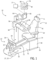
- a musculoskeletal stimulation device 10 may provide for a seat 12 presenting a substantially horizontal seating surface 14 extending along a horizontal plane 15 and a back support 16 extending upward from a rear edge 13 of the seating surface 14 along a vertical plane 17.
- the seat 12 may be positioned on an upstanding pedestal 18 comprising a box frame supported on a pedestal support structure 19.
- the pedestal support structure 19 supports the pedestal 18 above the floor 74 and may provide supporting feet extending vertically downward from the four corners of the pedestal support structure 19 or a horizontally extending rectangular platform supported substantially beneath the pedestal support structure 19.
- the back support 16 may be adjustable in inclination (reclining) to deviate from the vertical plane 17 as is generally understood in the art and may provide left and right arm supports 20 extending horizontally forward so that a seated user on the seat 12 may rest his or her forearms on the arm supports 20.
- the arm supports 20 may be pivotable upward against the sides of the back support 16 to facilitate ingress and egress from the seat 12.
- the back support 16 may provide a headrest 11 extending vertically upward along vertical plane 17 so that the seated user on the seat 12 may rest the back of his or her head on a support surface 21 of the headrest 11.
- the seat 12 may swivel about a vertical axis to facilitate ingress and egress.
- the seat 12, back support 16, arm supports 20, headrest 11, pedestal 18, and pedestal support 19 are each integrally constructed modular components which may be connected and disconnected from each other as desired to assemble or disassemble the device 10. Connection mechanisms between modular components may cooperate to form joined components as is generally understood in the art.
- the modular components may be joined by pins and sockets, interlocking fasteners, clamps, etc.
- Each of the modular components may be interchangeable with a variety of different sized components adopting to the various uses of the device 10 and its users.
- the height or width of the seat 12, pedestal 18, or pedestal support 19 may be adjusted by interchanging seat 12, pedestal 18, or pedestal support 19 components of varying dimensions.
- the modular components may include interchangeable components having different shapes, sizes, weights, material composition and aesthetic qualities.
- the pedestal 18 and pedestal support 19 support the seat 12 above the floor 74 and may be located relative to a force unit 22 so that the force unit 22 is positioned in front of the seat 12.
- Relative fixation between the seat 12 and the force unit 22 may be provided either by means of a connecting structure 24 communicating between the pedestal 18 or pedestal support 19 and the force unit 22 or by connection of both the pedestal 18 or pedestal support 19 and the force unit 22 directly to the floor 74 which then provides for this mechanical communication.
- relative fixation between the seat 12 and the force unit 22 may be provided for by sufficiently high friction forces between the floor 74 and the force unit 22 as well as between the floor 74 and the pedestal 18 or pedestal support 19 that exceed the force generated or applied through a user's legs.
- the force unit 22 supports a foot plate 26a facing the seat 12, for example, a textured foot plate 26a providing high friction forces between the user's feet and the textured foot plate 26a.
- the foot plate 26a is positioned to receive the feet of the user on a support surface 27 when the user is positioned in the seat 12 with his or her feet slightly elevated with bent knees.
- the top of the foot plate 26a may angle away from the user by about 30 degrees from vertical. Pressure by the feet and legs of the user against the foot plate 26a is resisted by the structure of the force unit 22 communicating through the connecting structure 24 or floor 74 to the pedestal 18 and the back support 16.
- the foot plate 26a may be a modular component that may be interchanged to provide a thinner foot plate 26b or otherwise different dimensions of foot plate 26a. Other variations may include different textures of the foot plate 26a surface and foot plates including at least two separate foot plates for each user foot which may be separately vibrated or force applied.
- the foot plate 26a supports a heel support 29a extending toward the user generally normal to the support surface 27 of the foot plate 26a so that heels of the feet of the user when the user is positioned in the seat 12 are supported below by the heel support 29a.
- a support surface 38 of the heel support 29a may angle away from the user by about 30 degrees from horizontal or an angle generally corresponding with the sloping angle of the top of the foot plate 26a.
- the heel support 29a may be a modular component that may be optionally installed or interchanged to provide a thicker heel support 29b or otherwise different dimensions of heel support 29a.
- the foot plate 26a may include mounting holes for attachment of the heel support 29a and other modular attachments such as upper extremity attachments and exercise attachments.
- a rear surface of the foot plate 26a may attach to a plate adapter 31a of the force unit 22.
- the plate adapter 31a may assist with desired angulation of the foot plate 26a to support the user's feet at the desired angle.
- the plate adapter 31a may provide angulation to the foot plate 26a by increasing or decreasing the thickness of the plate adapter 31a.
- the plate adapter 31a may be a wedge having a thick end tapering to a thin end whereby the thin end supports a bottom of the foot plate 26a and the thick end supports the top of the foot plate 26a.
- the plate adapter 31a may be a modular component that may be interchanged to provide a thicker wedge 31b or thinner wedge 31c.
- the thickness of the thick end may be decreased to increase the slope of the foot plate 26a from vertical and the thickness of the thick end may be increased to decrease the slope of the foot plate 26a from vertical.
- the plate adapter 31a may be magnetic to attach to magnetic components of the foot plate 26a and housing 33a for ease of attachment.
- the plate adapter 31 may articulate about a jointed component, such as a hinge for lateral side to side rocking motion, a ball joint for 360 degree rolling motion, or another articulating surface that maintains a controlled relative motion between the footplate 26 and the housing 22.
- a jointed component such as a hinge for lateral side to side rocking motion, a ball joint for 360 degree rolling motion, or another articulating surface that maintains a controlled relative motion between the footplate 26 and the housing 22.
- Adjustable articulation forces can be achieved whereby articulation is completely free and very little effort is required to articulate the jointed component or whereby an increased resistance makes it more difficult to articulate the joint.
- a rear surface of the plate adapter 31a may attach to a housing 33a supported above the floor 74 by a housing support 23a defined by bearings extending downwardly from the corners of the housing 33a and sliding along a rail, for example, provided by connecting structure 24 to change the relative location of the force unit 22 with respect to the seat 12. Movement of the force unit 22 along the rail may be facilitated by a magnetic load transfer assembly utilizing magnets to transmit the housing 33a along the rail.
- the housing support 23a may also be a horizontally extending platform supported beneath the housing 33a and providing an attachment surface for the restoring element 37, as further described below, or providing high friction forces between the floor 74.
- the housing 33a may have a beveled top edge 35 receiving the plate adapter 31a and promoting rearward sloping of the foot plate 26a by providing a beveled edge having an angle away from the user of about 40° from vertical and receiving the plate adapter 31a to decrease the angle of inclination.
- the plate adapter 31a may decrease the angle of the beveled top edge 35 to angle the foot plate 26a at an angle away from the user of about 30° from vertical.
- the housing 33a and the housing support 23a may be modular components that may be interchanged to provide components 33b, 33c and 23b, 23c, respectively, of different shapes or sizes.
- the housing support may take various constructions providing varied angled positioning of the foot plate 26a. It is also contemplated that the housing support 23a may be omitted and instead the housing 33a supported directly on the floor 74 or supported by a restoring element 37 as further described below.
- a base housing 70 may extend over the housing 33a and housing support 23a and further extend to cover the connecting structure 24, pedestal 18 and pedestal support 19 as desired to protect its contents from ingress of dirt and debris.
- Longitudinally extending slots 72 may allow the plate adapter 31a to extend through the base housing 70 allowing the foot plate 26a to reside outside of the base housing 70 while still communicating with the interior housing 33a.
- the slots 72 may extend between the force unit 22 and the seat 12 and allow the force unit 22 to be moved closer or farther away from the seat 12 depending on the length of the user's legs and the desired bend of the user's legs.
- the housing 33a may support or hold an actuator assembly 28 of the force unit 22 communicating with the foot plate 26a to impart a vibration motion 30 to the foot plate 26a along an actuation axis 34 generally normal to the support surface 27 of the foot plate 26a and aligned with the lower leg of the user.
- the vibration motion 30 may impart time-varying oscillations to the foot plate 26a at a temporal frequency which may be periodic or random.
- the oscillations may have a response magnitude defined by an excursion range about an equilibrium point that is less than the magnitude generally needed to compress the muscles of the legs.
- the vibration motion 30 may be provided by a vibrating motor (e.g., eccentric rotating mass vibration motor (ERM)) communicating with the foot plate 26a.
- EEM eccentric rotating mass vibration motor
- the vibration motion 30 may be provided by a pump that when pressed initiates spinning of a rotational component with an off-center mass. Spinning of the eccentrically-weighted rotational component causes vibration motion 30 which is translated to the pump and the foot plate 26a.
- the pump may be pressed by applying a force on the foot plate 26a, for example, by the user's feet applying force to the foot plate 26a.
- the pump may be adapter 31 or a part of plate adapter 31.
- the force unit 22 may further include a restoring element 37 imparting a restoring force 32 to the foot plate 26a substantially along the actuation axis 34.
- the restoring force 32 is greater than the forces applied by the vibration motion 30 to provide greater compression and expansion forces on the user's legs, not provided by the vibration motion 30 alone.
- An excursion range of the restoring force 32 is greater than the excursion range of the vibration motion 30 to provide a greater range of compression and expansion forces on the user's legs not provided by the vibration motion 30 only.
- the vibration motion 30 and the restoring force 32 may be actively resisted by conscious muscular action of the user in a dynamic mode or passively resisted by structure of the legs of the user as braced against knee bolsters 54 limiting the bending of the knees of the user in a passive mode.
- the restoring force may be resisted by the weight of the user's legs without a supporting structure for the knees.
- the muscles of the legs of the user are contracted by the vibration motion 30 through a natural stretch reflex of the muscles. Due to motion of the restoring element 37, the restoring force 32 is applied at a range of motion that articulates the joints and enables the muscles of the legs to pass through their optimal length for greatest force generation capacity.
- the restoring element 37 imparts the restoring force 32 against the foot plate 26a toward the user as the lower leg of the user extends to displace the foot plate 26a away from the user.
- the restoring force 32 decreases as the displacement of the foot plate 26a is increased and the restoring force 32 increases as the displacement of the foot plate 26a is decreased.
- the restoring element 37 is provided by a rocker 25a supporting the housing support 23a above a floor 74.
- the rocker 25a may be one or more arched structures extending between a front 41 of the housing 33a supporting the foot plate 26a and proximate the user, and a back 43 of the housing 33a away from the user, and providing a curved contact surface contacting the floor 74 at a point or along a line of points between the front 41 and back 43 of the housing 33a and allowing for forward rocking toward the user and backward rocking away from the user generally along a horizontal displacement axis 39.
- a center of mass 45 is located in a forward position with respect to a centerline 47 of the force unit 22 centered between the front 41 and back 43 of the housing 33a.
- a weight 42 of the force unit 22 is directed downwardly at the center of mass 45 causing an instantaneous point of rotation 44 to be located in a forward position on the curved contact surface such that the rocker 25a is tilted toward the user in the neutral position.
- the rocker 25a may be rocked backward causing the instantaneous point of rotation 44 to move backward along the curved contact surface such that the rocker 25a is tiled away from the user.
- the instantaneous point of rotation 44 is positioned along the centerline 47 such that the rocker 25a is in an upright, non-tilted position.
- the rocker 25a is tilted away from the user and the foot plate 26a and center of mass 45 are displaced along horizontal displacement axis 39 away from the user and raised along a vertical displacement axis 68.
- the displacement along the horizontal displacement axis 39 and vertical displacement axis 68 causes the joint range of motion of the user's leg to change throughout the displacement.
- the moment arm 48 between the center of mass 45 and the applied forward force 40 is greater as the rocker 25a is tilted away from the user if the line of action of force 40 is above center of mass 45.
- the moment arm 50 between the instantaneous point of rotation 44 and the applied weight 42 (weight of the force unit 22) is lower as the rocker 25a is tilted away from the user.
- the restoring force 32 decreases as the rocker 25a is tilted away from the user and displacement is greatest and the restoring force 32 increases as the rocker 25a is tilted toward the user and displacement is smallest.
- Adjusting the position of center of gravity 45 and changing the contour of rocker 25 and changing the position of applied force 40 has the effect of modifying restoring force 32 as the rocker tilts toward and away from the user.
- the rocker 25a may be a modular component and may be interchangeable to provide rockers 25b, 25c of varying radius of curvature, including a curve made of any number of connecting lines such that there are a finite number of points along the floor 74 about which the force unit tilts.
- the forward force 40 may be imparted by the user as separate forces on each respective foot.
- the foot plate 26a may include separate plates receiving each of the user's feet.
- the forward force 40 of one foot may generate the restoring force 32 on the opposite foot and vice versa.
- the restoring element 37 may include weights in cooperating operation with the separate vibration plates 26a.
- bolsters 54 may be generally padded cylinders extending across actuation axis 34 to fit on either side of the knees as separated by an equalizer arm 56.
- the equalizer arm 56 extending between the bolsters 54 may pivot at a pivot 58 midway along the equalizer arm 56 and join the equalizer arm 56 to one and of a swing arm 60.
- the swing arm 60 may communicate to its opposite end with the connecting structure 24 through a second pivot 62. In this way, the bolsters 54 may be moved down against the knees of the user by downward rotation of the swing arm 60 with rotation of the bolsters 54 about the pivot 58 equalizing force above and below the knees of the user.
- the swing arm 60 may be moved upward to move the bolsters 54 away from the knees of the user to allow the user to freely exit the device 10.
- the swing arm is not attached to the connecting structure 24 but is a free-standing structure that is supported on the floor 74 by locking rollers that allow the bolsters 54 to be rolled to the desired location but is not fixed to the device 10.
- the swing arm 60 may also support a device arm 64 supporting a user interface 66, for example, providing a touchscreen for receiving commands from the user and providing a display to the user. It is understood that the commands may also be received through physical buttons or virtual buttons shown on the user interface 66.
- the various components of the device 10 may be controlled by a controller 77 providing one or more electronic computer 78 processors communicating with electronic memory 80 for storing a program 82 to be executed by the electronic computer 78 according to data and the program 82 in the memory 80.
- the memory 80 provides a non-transient storage medium for the program 82.
- the controller 77 may communicate with the user interface 66, the actuator assembly 28, and the restoring element 37 for electronically controlling the vibration motion 30 and restoring force 32.
- the controller 77 may operate to change the vibration motion 30 and restoring force 32 depending on the operating program 82 to provide strength assessments, range of motion assessments, and other assessments.
- the operating program 82 may monitor the amount of forward force 40 acting on the foot plate 26a and provide feedback to the patient, therapist, or other third party through the user interface 66 or other monitor to show force versus time for varying amounts of vibration motion 30 and restoring force 32.
- the patient is instructed to maintain a constant forward force 40 as the amounts of vibration motion 30 and restoring force 32 applied changes.
- the amount of forward force 40 applied by the user may be indicated on the user interface 66.
- a score is provided to the user at the end of the session.
- the operating program 82 may monitor the amount of movement 32 of the foot plate 26a and provide feedback to the patient, therapist, or other third party through the user interface 66 or other monitor to show the range of motion of the user's limb and the restoring force 32 as a function of range of motion.
- the program 82 may further provide instructions to the user interface 66 in order to communicate passive range of motion exercises, active exercises, cognitive exercises, team competitive and collaborative exercises, remote competitive and collaborative exercises to the user in connection with use of the device 10.
- the program 82 may also provide assessment tools such as range of motion testing (via stepper motor count), strength testing (via load cell), circulation testing (via thermal imaging), stress testing (via skin conductance), cognitive testing (via on-screen assessments), and vibro-tactile sensation testing.
- Other programs 82 may include educational and training software and service and maintenance programs 82.
- Results of the program 82 may be reported to the user and/or outside third parties customized to each particular user. Third parties receiving the reporting information may use the information to gather global data, make comparisons between users, and assess the progress of the user. Results of the program 82 may also be communicated through social media.
- Additional modular components may be optionally attached to the device 10 including body positioning mechanisms, for example, knee supports (manual or automatic), posture alignment supports, cushions; exercise attachments, for example, seated row via foot braces plus handles attached to the foot plate 26a), bench press (via push bar attached to the foot plate 26a) and straps 76 or handles; and sensors, for example, load cells, limit switches, tilt sensors, accelerometers, biosensors.
- body positioning mechanisms for example, knee supports (manual or automatic), posture alignment supports, cushions; exercise attachments, for example, seated row via foot braces plus handles attached to the foot plate 26a), bench press (via push bar attached to the foot plate 26a) and straps 76 or handles; and sensors, for example, load cells, limit switches, tilt sensors, accelerometers, biosensors.
- the force unit 22 may be a standalone exercise device whereby the foot plate 26a is supported by a rocking or pivotable housing 33a (similar to the housing 33a shown in figures 3 through 5 ) whereby the restoring force 32 is applied by gravity (without straps 76).
- the foot plate 26a may be integral with the housing 33a such that an angled foot plate 26a provides a side of the housing 33a as shown.
- the housing 33a when the force unit 22 is at a neutral position without any application of forward force 40, the housing 33a may be substantially horizontal and extending along displacement axis 39.
- the forward force 40 When the forward force 40 is imparted by conscious muscular action of the user when he or she pushes against the foot plate 26a, the housing 33a pivots upward away from the user.
- the forward force 40 causes displacement of the foot plate 26a along the displacement axis 39 away from the user and raised along the vertical displacement axis 68.
- the restoring force 32 can be the force of gravity when the location of the center of gravity 45 of force unit 22 is proximal the point about which force unit 22 rocks on floor 74.
- references to "a controller” can be understood to include one or more microprocessors that can communicate in a stand-alone and/or a distributed environment(s), and can thus be configured to communicate via wired or wireless communications with other processors, where such one or more processor can be configured to operate on one or more processor-controlled devices that can be similar or different devices.
- references to memory can include one or more processor-readable and accessible memory elements and/or components that can be internal to the processor-controlled device, external to the processor-controlled device, and can be accessed via a wired or wireless network.
Landscapes
- Health & Medical Sciences (AREA)
- Life Sciences & Earth Sciences (AREA)
- General Health & Medical Sciences (AREA)
- Physical Education & Sports Medicine (AREA)
- Animal Behavior & Ethology (AREA)
- Rehabilitation Therapy (AREA)
- Pain & Pain Management (AREA)
- Epidemiology (AREA)
- Public Health (AREA)
- Veterinary Medicine (AREA)
- Biophysics (AREA)
- Orthopedic Medicine & Surgery (AREA)
- Rehabilitation Tools (AREA)
Claims (8)
- Vorrichtung (10) zum Aufbringen einer Vibrationskraft auf ein Glied eines Benutzers der Vorrichtung (10), wobei die Vorrichtung Folgendes umfasst:eine Fußplatte (26a) zur Aufnahme des Fußes eines Benutzers;ein Vibrationssystem (28), das mit der Fußplatte (26a) in Verbindung steht, um eine Vibrationskraft auf den Fuß innerhalb eines ersten Auslenkungsbereichs auszuüben, wobei die Vibrationskraft entlang einer Betätigungsachse senkrecht zu einer Stützfläche (27) der Fußplatte (26a) verläuft; undein Rückstellelement, das über einen zweiten Auslenkungsbereich, der größer als der erste Auslenkungsbereich ist, eine Rückstellkraft auf die Fußplatte (26a) ausübt, dadurch gekennzeichnet, dass:
das Rückstellelement ein Gewicht mit einem Schwerpunkt ist, wobei das Gewicht die Rückstellkraft in Abhängigkeit von einer Verschiebung der Fußplatte (26a) aus einer neutralen Position durch ein Wippen oder Schwenken der Fußplatte (26a) bereitstellt. - Vorrichtung (10) nach Anspruch 1, die so konfiguriert ist, dass der Schwerpunkt des Gewichts bei einer Verschiebung der Fußplatte (26a) entlang einer vertikalen Achse angehoben wird.
- Vorrichtung (10) nach Anspruch 2, wobei das Gewicht durch eine Wippe bereitgestellt wird, die eine wippende Bewegung der Fußplatte (26a) zum Benutzer hin und von ihm weg ermöglicht, wobei eine Verschiebung der Fußplatte (26a) erfolgt, wenn sie von dem Benutzer weg gewippt wird, und die Rückstellkraft auf die Fußplatte (26a) ausgeübt wird, wenn sie zu dem Benutzer hin gewippt wird.
- Vorrichtung (10) nach Anspruch 3, wobei die Wippe austauschbar ist, um einen Krümmungsradius der Wippe zu verändern.
- Vorrichtung (10) nach Anspruch 1, die zwei der Fußplatten (26a) umfasst, wobei die beiden Fußplatten (26a) zwei separat verschiebbare Fußplatten (26a) zur separaten Aufnahme der Füße des Benutzers sind und die Rückstellkraft für jede Fußplatte durch Verschieben der anderen Fußplatte erzeugt wird.
- Vorrichtung (10) nach Anspruch 1, wobei die Fußplatte (26a) austauschbar ist, um eine Abmessung der Fußplatte (26a) zu ändern.
- Vorrichtung (10) nach Anspruch 1, wobei die Fußplatte (26a) ferner eine Fersenstütze (29a) umfasst, um eine Ferse eines Benutzers aufzunehmen, wenn sich der Benutzer in einer Sitzposition befindet.
- Vorrichtung (10) nach Anspruch 1, wobei die Verschiebung der Fußplatte (26a) entlang mindestens zweier orthogonaler Richtungen erfolgt.
Applications Claiming Priority (2)
| Application Number | Priority Date | Filing Date | Title |
|---|---|---|---|
| US201662414387P | 2016-10-28 | 2016-10-28 | |
| PCT/US2017/058967 WO2018081680A1 (en) | 2016-10-28 | 2017-10-30 | Modular therapeutic vibration rehabilitation system |
Publications (4)
| Publication Number | Publication Date |
|---|---|
| EP3532004A1 EP3532004A1 (de) | 2019-09-04 |
| EP3532004A4 EP3532004A4 (de) | 2020-06-03 |
| EP3532004B1 true EP3532004B1 (de) | 2023-06-07 |
| EP3532004C0 EP3532004C0 (de) | 2023-06-07 |
Family
ID=62024074
Family Applications (1)
| Application Number | Title | Priority Date | Filing Date |
|---|---|---|---|
| EP17864579.2A Active EP3532004B1 (de) | 2016-10-28 | 2017-10-30 | Modulares therapeutisches vibrationssystem für rehabilitation |
Country Status (3)
| Country | Link |
|---|---|
| US (1) | US20200046591A1 (de) |
| EP (1) | EP3532004B1 (de) |
| WO (1) | WO2018081680A1 (de) |
Families Citing this family (6)
| Publication number | Priority date | Publication date | Assignee | Title |
|---|---|---|---|---|
| US20200238131A1 (en) * | 2019-01-28 | 2020-07-30 | Zhejiang Ciapo Sporting Goods Co., Ltd | Walking Machine |
| US11446191B2 (en) | 2019-04-19 | 2022-09-20 | Hill-Rom Services, Inc. | Patient bed having exercise therapy apparatus |
| CN111803332B (zh) * | 2020-08-24 | 2022-02-22 | 深圳市艾利特医疗科技有限公司 | 一种小儿脑瘫康复使用装置 |
| CN112043558B (zh) * | 2020-09-14 | 2022-05-10 | 西安理工大学 | 一种兼具康复训练和助力行走的下肢外骨骼康复机器人 |
| CN112618255B (zh) * | 2020-12-14 | 2022-11-29 | 山东欣悦健康科技有限公司 | 一种医疗腿骨康复理疗机构 |
| US20240148606A1 (en) * | 2022-11-03 | 2024-05-09 | Vibetech, Inc. | Apparatus for providing automatically dosed activity |
Family Cites Families (10)
| Publication number | Priority date | Publication date | Assignee | Title |
|---|---|---|---|---|
| US2845063A (en) * | 1957-01-03 | 1958-07-29 | Charles S Allen | Exercising device |
| US3712613A (en) * | 1971-05-05 | 1973-01-23 | J Feather | Exercising machine |
| US3841320A (en) * | 1973-08-30 | 1974-10-15 | J Brown | Kinesitherapy appliance |
| US6152855A (en) * | 1999-02-03 | 2000-11-28 | Synergy Innovations, Inc. | In-bed exercise machine and method of use |
| WO2003088888A2 (en) | 2002-04-18 | 2003-10-30 | University Of Florida | Musculoskeletal loading device |
| DE10323273A1 (de) | 2003-05-21 | 2004-12-16 | Egger, Norbert, Dr. | Nachrüstsatz für Trainingsgerät und Trainingsgerät |
| EP1656921B1 (de) * | 2004-11-10 | 2007-04-25 | IBFK GmbH International Biotechnological Future Knowledge | Trainingsgerät |
| US8485945B2 (en) * | 2009-10-02 | 2013-07-16 | Duodesk Llc | Fully adjustable integrated exercise workstation |
| US9283134B2 (en) | 2011-02-15 | 2016-03-15 | Wisys Technology Foundation, Inc. | Vibration unit for musculoskeletal vibrations system for jointed limbs |
| US10123928B2 (en) | 2013-03-15 | 2018-11-13 | Wisys Technology Foundation, Inc. | Musculoskeletal vibration system providing independent vibration and bias control |
-
2017
- 2017-10-30 EP EP17864579.2A patent/EP3532004B1/de active Active
- 2017-10-30 WO PCT/US2017/058967 patent/WO2018081680A1/en not_active Ceased
- 2017-10-30 US US16/345,916 patent/US20200046591A1/en not_active Abandoned
Also Published As
| Publication number | Publication date |
|---|---|
| EP3532004A1 (de) | 2019-09-04 |
| WO2018081680A1 (en) | 2018-05-03 |
| US20200046591A1 (en) | 2020-02-13 |
| EP3532004A4 (de) | 2020-06-03 |
| EP3532004C0 (de) | 2023-06-07 |
Similar Documents
| Publication | Publication Date | Title |
|---|---|---|
| US20200046591A1 (en) | Modular Therapeutic Vibration Rehabilitation System | |
| US11590045B2 (en) | Apparatus for stimulating synchronized body motions of a user | |
| JP3988642B2 (ja) | バランス訓練装置 | |
| US9895282B2 (en) | Exercise and gait-training apparatus | |
| US20080020911A1 (en) | Squatting apparatus without spinal column compression | |
| KR20040029963A (ko) | 운동기구 | |
| US7452308B2 (en) | Cross-crawl chair | |
| CN101909572A (zh) | 立姿用被动锻炼设备 | |
| CA2906579A1 (en) | Musculoskeletal vibration system providing independent vibration and bias control | |
| US11696864B2 (en) | Upper body attachment apparatus for whole body vibration equipment | |
| US10130835B1 (en) | Three exercise combination device to alleviate sciatica and low back pain | |
| KR101556833B1 (ko) | 앉음용 가구 유닛 | |
| WO2008026336A1 (en) | Sporting device | |
| EP2369957A2 (de) | Gymnastikstuhl zur stimulierung des muskel-skelett-systems | |
| KR100943968B1 (ko) | 하지기능평가 재활운동기기 | |
| JP6612386B2 (ja) | 健康器具 | |
| JP2005168514A (ja) | 運動用器具の腰掛けおよび運動用器具 | |
| JP3255423U (ja) | 腰部位改善運動用具 | |
| KR20080109500A (ko) | 등받이 조절장치를 갖는 허리운동기구 | |
| RU2843218C1 (ru) | Тренажер для поясничного отдела позвоночника и тазобедренных суставов | |
| TWI620557B (zh) | Inclined spine swing machine | |
| RU2837297C1 (ru) | Роботизированное кресло-тренажер | |
| KR102714458B1 (ko) | 재활 운동용 좌우 가변 회전 페달형 운동기구 | |
| JP3254736U (ja) | 腕・背の運動用具 | |
| KR102071359B1 (ko) | 환자 재활치료용 운동기구 |
Legal Events
| Date | Code | Title | Description |
|---|---|---|---|
| STAA | Information on the status of an ep patent application or granted ep patent |
Free format text: STATUS: THE INTERNATIONAL PUBLICATION HAS BEEN MADE |
|
| PUAI | Public reference made under article 153(3) epc to a published international application that has entered the european phase |
Free format text: ORIGINAL CODE: 0009012 |
|
| STAA | Information on the status of an ep patent application or granted ep patent |
Free format text: STATUS: REQUEST FOR EXAMINATION WAS MADE |
|
| 17P | Request for examination filed |
Effective date: 20190528 |
|
| AK | Designated contracting states |
Kind code of ref document: A1 Designated state(s): AL AT BE BG CH CY CZ DE DK EE ES FI FR GB GR HR HU IE IS IT LI LT LU LV MC MK MT NL NO PL PT RO RS SE SI SK SM TR |
|
| AX | Request for extension of the european patent |
Extension state: BA ME |
|
| DAV | Request for validation of the european patent (deleted) | ||
| DAX | Request for extension of the european patent (deleted) | ||
| A4 | Supplementary search report drawn up and despatched |
Effective date: 20200504 |
|
| RIC1 | Information provided on ipc code assigned before grant |
Ipc: A63B 21/04 20060101ALI20200427BHEP Ipc: A63B 23/035 20060101ALI20200427BHEP Ipc: A61H 1/00 20060101ALI20200427BHEP Ipc: A61H 23/02 20060101AFI20200427BHEP Ipc: A63B 21/055 20060101ALI20200427BHEP Ipc: A63B 21/00 20060101ALI20200427BHEP |
|
| STAA | Information on the status of an ep patent application or granted ep patent |
Free format text: STATUS: EXAMINATION IS IN PROGRESS |
|
| 17Q | First examination report despatched |
Effective date: 20210607 |
|
| GRAP | Despatch of communication of intention to grant a patent |
Free format text: ORIGINAL CODE: EPIDOSNIGR1 |
|
| STAA | Information on the status of an ep patent application or granted ep patent |
Free format text: STATUS: GRANT OF PATENT IS INTENDED |
|
| INTG | Intention to grant announced |
Effective date: 20211208 |
|
| RIN1 | Information on inventor provided before grant (corrected) |
Inventor name: LEISMER, JEFFREY, M. |
|
| GRAJ | Information related to disapproval of communication of intention to grant by the applicant or resumption of examination proceedings by the epo deleted |
Free format text: ORIGINAL CODE: EPIDOSDIGR1 |
|
| STAA | Information on the status of an ep patent application or granted ep patent |
Free format text: STATUS: EXAMINATION IS IN PROGRESS |
|
| INTC | Intention to grant announced (deleted) | ||
| GRAP | Despatch of communication of intention to grant a patent |
Free format text: ORIGINAL CODE: EPIDOSNIGR1 |
|
| STAA | Information on the status of an ep patent application or granted ep patent |
Free format text: STATUS: GRANT OF PATENT IS INTENDED |
|
| INTG | Intention to grant announced |
Effective date: 20220902 |
|
| GRAS | Grant fee paid |
Free format text: ORIGINAL CODE: EPIDOSNIGR3 |
|
| GRAA | (expected) grant |
Free format text: ORIGINAL CODE: 0009210 |
|
| STAA | Information on the status of an ep patent application or granted ep patent |
Free format text: STATUS: THE PATENT HAS BEEN GRANTED |
|
| AK | Designated contracting states |
Kind code of ref document: B1 Designated state(s): AL AT BE BG CH CY CZ DE DK EE ES FI FR GB GR HR HU IE IS IT LI LT LU LV MC MK MT NL NO PL PT RO RS SE SI SK SM TR |
|
| REG | Reference to a national code |
Ref country code: GB Ref legal event code: FG4D |
|
| REG | Reference to a national code |
Ref country code: CH Ref legal event code: EP Ref country code: AT Ref legal event code: REF Ref document number: 1572685 Country of ref document: AT Kind code of ref document: T Effective date: 20230615 |
|
| REG | Reference to a national code |
Ref country code: DE Ref legal event code: R096 Ref document number: 602017069966 Country of ref document: DE |
|
| U01 | Request for unitary effect filed |
Effective date: 20230707 |
|
| U07 | Unitary effect registered |
Designated state(s): AT BE BG DE DK EE FI FR IT LT LU LV MT NL PT SE SI Effective date: 20230802 |
|
| REG | Reference to a national code |
Ref country code: LT Ref legal event code: MG9D |
|
| PG25 | Lapsed in a contracting state [announced via postgrant information from national office to epo] |
Ref country code: NO Free format text: LAPSE BECAUSE OF FAILURE TO SUBMIT A TRANSLATION OF THE DESCRIPTION OR TO PAY THE FEE WITHIN THE PRESCRIBED TIME-LIMIT Effective date: 20230907 Ref country code: ES Free format text: LAPSE BECAUSE OF FAILURE TO SUBMIT A TRANSLATION OF THE DESCRIPTION OR TO PAY THE FEE WITHIN THE PRESCRIBED TIME-LIMIT Effective date: 20230607 |
|
| PG25 | Lapsed in a contracting state [announced via postgrant information from national office to epo] |
Ref country code: RS Free format text: LAPSE BECAUSE OF FAILURE TO SUBMIT A TRANSLATION OF THE DESCRIPTION OR TO PAY THE FEE WITHIN THE PRESCRIBED TIME-LIMIT Effective date: 20230607 Ref country code: HR Free format text: LAPSE BECAUSE OF FAILURE TO SUBMIT A TRANSLATION OF THE DESCRIPTION OR TO PAY THE FEE WITHIN THE PRESCRIBED TIME-LIMIT Effective date: 20230607 Ref country code: GR Free format text: LAPSE BECAUSE OF FAILURE TO SUBMIT A TRANSLATION OF THE DESCRIPTION OR TO PAY THE FEE WITHIN THE PRESCRIBED TIME-LIMIT Effective date: 20230908 |
|
| PG25 | Lapsed in a contracting state [announced via postgrant information from national office to epo] |
Ref country code: SK Free format text: LAPSE BECAUSE OF FAILURE TO SUBMIT A TRANSLATION OF THE DESCRIPTION OR TO PAY THE FEE WITHIN THE PRESCRIBED TIME-LIMIT Effective date: 20230607 |
|
| PG25 | Lapsed in a contracting state [announced via postgrant information from national office to epo] |
Ref country code: IS Free format text: LAPSE BECAUSE OF FAILURE TO SUBMIT A TRANSLATION OF THE DESCRIPTION OR TO PAY THE FEE WITHIN THE PRESCRIBED TIME-LIMIT Effective date: 20231007 |
|
| PG25 | Lapsed in a contracting state [announced via postgrant information from national office to epo] |
Ref country code: SM Free format text: LAPSE BECAUSE OF FAILURE TO SUBMIT A TRANSLATION OF THE DESCRIPTION OR TO PAY THE FEE WITHIN THE PRESCRIBED TIME-LIMIT Effective date: 20230607 Ref country code: SK Free format text: LAPSE BECAUSE OF FAILURE TO SUBMIT A TRANSLATION OF THE DESCRIPTION OR TO PAY THE FEE WITHIN THE PRESCRIBED TIME-LIMIT Effective date: 20230607 Ref country code: RO Free format text: LAPSE BECAUSE OF FAILURE TO SUBMIT A TRANSLATION OF THE DESCRIPTION OR TO PAY THE FEE WITHIN THE PRESCRIBED TIME-LIMIT Effective date: 20230607 Ref country code: IS Free format text: LAPSE BECAUSE OF FAILURE TO SUBMIT A TRANSLATION OF THE DESCRIPTION OR TO PAY THE FEE WITHIN THE PRESCRIBED TIME-LIMIT Effective date: 20231007 Ref country code: CZ Free format text: LAPSE BECAUSE OF FAILURE TO SUBMIT A TRANSLATION OF THE DESCRIPTION OR TO PAY THE FEE WITHIN THE PRESCRIBED TIME-LIMIT Effective date: 20230607 |
|
| PG25 | Lapsed in a contracting state [announced via postgrant information from national office to epo] |
Ref country code: PL Free format text: LAPSE BECAUSE OF FAILURE TO SUBMIT A TRANSLATION OF THE DESCRIPTION OR TO PAY THE FEE WITHIN THE PRESCRIBED TIME-LIMIT Effective date: 20230607 |
|
| REG | Reference to a national code |
Ref country code: DE Ref legal event code: R097 Ref document number: 602017069966 Country of ref document: DE |
|
| PLBE | No opposition filed within time limit |
Free format text: ORIGINAL CODE: 0009261 |
|
| STAA | Information on the status of an ep patent application or granted ep patent |
Free format text: STATUS: NO OPPOSITION FILED WITHIN TIME LIMIT |
|
| 26N | No opposition filed |
Effective date: 20240308 |
|
| U21 | Renewal fee for the european patent with unitary effect paid with additional fee |
Year of fee payment: 7 Effective date: 20240422 |
|
| PG25 | Lapsed in a contracting state [announced via postgrant information from national office to epo] |
Ref country code: MC Free format text: LAPSE BECAUSE OF FAILURE TO SUBMIT A TRANSLATION OF THE DESCRIPTION OR TO PAY THE FEE WITHIN THE PRESCRIBED TIME-LIMIT Effective date: 20230607 |
|
| REG | Reference to a national code |
Ref country code: CH Ref legal event code: PL |
|
| GBPC | Gb: european patent ceased through non-payment of renewal fee |
Effective date: 20231030 |
|
| PG25 | Lapsed in a contracting state [announced via postgrant information from national office to epo] |
Ref country code: GB Free format text: LAPSE BECAUSE OF NON-PAYMENT OF DUE FEES Effective date: 20231030 |
|
| PG25 | Lapsed in a contracting state [announced via postgrant information from national office to epo] |
Ref country code: CH Free format text: LAPSE BECAUSE OF NON-PAYMENT OF DUE FEES Effective date: 20231031 |
|
| PG25 | Lapsed in a contracting state [announced via postgrant information from national office to epo] |
Ref country code: GB Free format text: LAPSE BECAUSE OF NON-PAYMENT OF DUE FEES Effective date: 20231030 Ref country code: CH Free format text: LAPSE BECAUSE OF NON-PAYMENT OF DUE FEES Effective date: 20231031 |
|
| PG25 | Lapsed in a contracting state [announced via postgrant information from national office to epo] |
Ref country code: IE Free format text: LAPSE BECAUSE OF NON-PAYMENT OF DUE FEES Effective date: 20231030 |
|
| PG25 | Lapsed in a contracting state [announced via postgrant information from national office to epo] |
Ref country code: IE Free format text: LAPSE BECAUSE OF NON-PAYMENT OF DUE FEES Effective date: 20231030 |
|
| U90 | Renewal fees not paid: noting of loss of rights |
Free format text: RENEWAL FEE NOT PAID FOR YEAR 08 Effective date: 20250521 |
|
| PG25 | Lapsed in a contracting state [announced via postgrant information from national office to epo] |
Ref country code: CY Free format text: LAPSE BECAUSE OF FAILURE TO SUBMIT A TRANSLATION OF THE DESCRIPTION OR TO PAY THE FEE WITHIN THE PRESCRIBED TIME-LIMIT; INVALID AB INITIO Effective date: 20171030 |
|
| PG25 | Lapsed in a contracting state [announced via postgrant information from national office to epo] |
Ref country code: HU Free format text: LAPSE BECAUSE OF FAILURE TO SUBMIT A TRANSLATION OF THE DESCRIPTION OR TO PAY THE FEE WITHIN THE PRESCRIBED TIME-LIMIT; INVALID AB INITIO Effective date: 20171030 |
|
| REG | Reference to a national code |
Ref country code: GB Ref legal event code: S28 Free format text: APPLICATION FILED |
|
| U93 | Unitary patent lapsed |
Free format text: RENEWAL FEE NOT PAID Effective date: 20241031 |
|
| PG25 | Lapsed in a contracting state [announced via postgrant information from national office to epo] |
Ref country code: TR Free format text: LAPSE BECAUSE OF FAILURE TO SUBMIT A TRANSLATION OF THE DESCRIPTION OR TO PAY THE FEE WITHIN THE PRESCRIBED TIME-LIMIT Effective date: 20230607 |
|
| REG | Reference to a national code |
Ref country code: GB Ref legal event code: S28 Free format text: RESTORATION ALLOWED Effective date: 20251215 |
|
| PG25 | Lapsed in a contracting state [announced via postgrant information from national office to epo] |
Ref country code: GB Free format text: LAPSE BECAUSE OF NON-PAYMENT OF DUE FEES Effective date: 20231030 |
|
| PGFP | Annual fee paid to national office [announced via postgrant information from national office to epo] |
Ref country code: GB Payment date: 20251201 Year of fee payment: 9 |
|
| PGRI | Patent reinstated in contracting state [announced from national office to epo] |
Ref country code: GB Effective date: 20251215 |