EP3530857B1 - Procédé de commande en fonctionnement d'un dispositif d'entraînement motorisé d'une fenêtre pour un bâtiment, fenêtre et installation domotique associés - Google Patents
Procédé de commande en fonctionnement d'un dispositif d'entraînement motorisé d'une fenêtre pour un bâtiment, fenêtre et installation domotique associés Download PDFInfo
- Publication number
- EP3530857B1 EP3530857B1 EP19159562.8A EP19159562A EP3530857B1 EP 3530857 B1 EP3530857 B1 EP 3530857B1 EP 19159562 A EP19159562 A EP 19159562A EP 3530857 B1 EP3530857 B1 EP 3530857B1
- Authority
- EP
- European Patent Office
- Prior art keywords
- frame
- respect
- fixed frame
- openable part
- window
- Prior art date
- Legal status (The legal status is an assumption and is not a legal conclusion. Google has not performed a legal analysis and makes no representation as to the accuracy of the status listed.)
- Active
Links
Images


Classifications
-
- E—FIXED CONSTRUCTIONS
- E05—LOCKS; KEYS; WINDOW OR DOOR FITTINGS; SAFES
- E05F—DEVICES FOR MOVING WINGS INTO OPEN OR CLOSED POSITION; CHECKS FOR WINGS; WING FITTINGS NOT OTHERWISE PROVIDED FOR, CONCERNED WITH THE FUNCTIONING OF THE WING
- E05F15/00—Power-operated mechanisms for wings
- E05F15/60—Power-operated mechanisms for wings using electrical actuators
- E05F15/603—Power-operated mechanisms for wings using electrical actuators using rotary electromotors
- E05F15/632—Power-operated mechanisms for wings using electrical actuators using rotary electromotors for horizontally-sliding wings
- E05F15/643—Power-operated mechanisms for wings using electrical actuators using rotary electromotors for horizontally-sliding wings operated by flexible elongated pulling elements, e.g. belts, chains or cables
-
- E—FIXED CONSTRUCTIONS
- E05—LOCKS; KEYS; WINDOW OR DOOR FITTINGS; SAFES
- E05Y—INDEXING SCHEME ASSOCIATED WITH SUBCLASSES E05D AND E05F, RELATING TO CONSTRUCTION ELEMENTS, ELECTRIC CONTROL, POWER SUPPLY, POWER SIGNAL OR TRANSMISSION, USER INTERFACES, MOUNTING OR COUPLING, DETAILS, ACCESSORIES, AUXILIARY OPERATIONS NOT OTHERWISE PROVIDED FOR, APPLICATION THEREOF
- E05Y2400/00—Electronic control; Electrical power; Power supply; Power or signal transmission; User interfaces
- E05Y2400/10—Electronic control
- E05Y2400/30—Electronic control of motors
- E05Y2400/3013—Electronic control of motors during manual wing operation
- E05Y2400/3014—Back driving the transmission or motor
-
- E—FIXED CONSTRUCTIONS
- E05—LOCKS; KEYS; WINDOW OR DOOR FITTINGS; SAFES
- E05Y—INDEXING SCHEME ASSOCIATED WITH SUBCLASSES E05D AND E05F, RELATING TO CONSTRUCTION ELEMENTS, ELECTRIC CONTROL, POWER SUPPLY, POWER SIGNAL OR TRANSMISSION, USER INTERFACES, MOUNTING OR COUPLING, DETAILS, ACCESSORIES, AUXILIARY OPERATIONS NOT OTHERWISE PROVIDED FOR, APPLICATION THEREOF
- E05Y2400/00—Electronic control; Electrical power; Power supply; Power or signal transmission; User interfaces
- E05Y2400/10—Electronic control
- E05Y2400/32—Position control, detection or monitoring
-
- E—FIXED CONSTRUCTIONS
- E05—LOCKS; KEYS; WINDOW OR DOOR FITTINGS; SAFES
- E05Y—INDEXING SCHEME ASSOCIATED WITH SUBCLASSES E05D AND E05F, RELATING TO CONSTRUCTION ELEMENTS, ELECTRIC CONTROL, POWER SUPPLY, POWER SIGNAL OR TRANSMISSION, USER INTERFACES, MOUNTING OR COUPLING, DETAILS, ACCESSORIES, AUXILIARY OPERATIONS NOT OTHERWISE PROVIDED FOR, APPLICATION THEREOF
- E05Y2400/00—Electronic control; Electrical power; Power supply; Power or signal transmission; User interfaces
- E05Y2400/10—Electronic control
- E05Y2400/32—Position control, detection or monitoring
- E05Y2400/334—Position control, detection or monitoring by using pulse generators
- E05Y2400/336—Position control, detection or monitoring by using pulse generators of the angular type
-
- E—FIXED CONSTRUCTIONS
- E05—LOCKS; KEYS; WINDOW OR DOOR FITTINGS; SAFES
- E05Y—INDEXING SCHEME ASSOCIATED WITH SUBCLASSES E05D AND E05F, RELATING TO CONSTRUCTION ELEMENTS, ELECTRIC CONTROL, POWER SUPPLY, POWER SIGNAL OR TRANSMISSION, USER INTERFACES, MOUNTING OR COUPLING, DETAILS, ACCESSORIES, AUXILIARY OPERATIONS NOT OTHERWISE PROVIDED FOR, APPLICATION THEREOF
- E05Y2900/00—Application of doors, windows, wings or fittings thereof
- E05Y2900/10—Application of doors, windows, wings or fittings thereof for buildings or parts thereof
- E05Y2900/13—Type of wing
- E05Y2900/132—Doors
-
- E—FIXED CONSTRUCTIONS
- E05—LOCKS; KEYS; WINDOW OR DOOR FITTINGS; SAFES
- E05Y—INDEXING SCHEME ASSOCIATED WITH SUBCLASSES E05D AND E05F, RELATING TO CONSTRUCTION ELEMENTS, ELECTRIC CONTROL, POWER SUPPLY, POWER SIGNAL OR TRANSMISSION, USER INTERFACES, MOUNTING OR COUPLING, DETAILS, ACCESSORIES, AUXILIARY OPERATIONS NOT OTHERWISE PROVIDED FOR, APPLICATION THEREOF
- E05Y2900/00—Application of doors, windows, wings or fittings thereof
- E05Y2900/10—Application of doors, windows, wings or fittings thereof for buildings or parts thereof
- E05Y2900/13—Type of wing
- E05Y2900/148—Windows
Definitions
- the present invention relates to a method of operating a motorized drive device of a window for a building, so as to move an opening relative to a fixed frame and to lock the opening relative to the fixed frame in at least one predetermined locked position.
- the present invention also relates to a window for a building incorporating such a motorized drive device, as well as a home automation installation comprising such a window.
- the present invention relates to the field of windows comprising a motorized drive device setting an opening leaf in motion relative to a fixed frame, between at least a first position and at least a second position.
- a motorized drive device for such a window comprises an electromechanical actuator.
- the motorized drive device comprises an electromechanical actuator, an electronic control unit, a flexible element and a drive arm.
- the electromechanical actuator includes an electric motor.
- the flexible element is configured to drive the opening leaf relative to the fixed frame, when the electromechanical actuator is electrically activated.
- the drive arm is connected, on the one hand, to a lateral upright of a frame of the opening and, on the other hand, to the flexible element.
- the locking device is arranged inside a side post of a frame of the opening.
- the lateral upright of the opening frame is configured to cooperate with the fixed frame in a closed position of the opening relative to the fixed frame.
- the drive arm is integral with a shaft of the locking device and mounted to be movable in rotation about an axis of rotation of the shaft of the locking device.
- the object of the present invention is to resolve the aforementioned drawbacks and to propose a method for controlling in operation a motorized drive device for a window for a building, a window for a building comprising such a motorized drive device, as well as a home automation installation comprising such a window, making it possible to determine a current position of the opening relative to the fixed frame during a movement of the opening relative to the fixed frame, both motorized and manually, all by guaranteeing the safety of a user, in particular when reaching an end-of-travel position or a predetermined position, and by limiting the consumption of electrical energy by the motorized drive device.
- the motorized drive device also comprises a counting device.
- the counting device includes at least one sensor.
- the counting device is configured to cooperate with the electronic control unit.
- the counting device and the electronic control unit are configured to determine a position of the opening relative to the fixed frame.
- the predetermined frequency has at least a first value.
- the predetermined frequency has a zero value or a second value, the second value of the predetermined frequency being less than the first value of the predetermined frequency.
- the monitoring step is implemented according to a third value of the predetermined frequency, the third value of the predetermined frequency being greater than the first value of the predetermined frequency.
- the motorized drive device makes it possible to determine a current position of the opening relative to the fixed frame, by means of the counting device and the electronic control unit, during a movement of the opening relative to the fixed frame.
- the fixed frame implemented either by means of the motorized drive device or manually by a user, that is to say without electrically activating the electromechanical actuator, while ensuring the safety of the user, in particular during of reaching an end-of-travel position or a predetermined position, and by limiting the consumption of electrical energy of the motorized drive device.
- the counting device and the electronic control unit are configured to determine a position of the opening relative to the fixed frame at any time, by means of the sensor (s) of the counting device, so as to guarantee the safety of the user.
- monitoring of the signal from the counting device by the electronic control unit is operated according to the first value of the predetermined frequency.
- the monitoring of the signal from the counting device by the electronic control unit is either deactivated, i.e. the predetermined frequency of monitoring of the signal from the counting device by the electronic control unit is zero, or implemented according to the second value of the predetermined frequency.
- the method comprises a first step of resetting the position of the opening relative to the fixed frame by the counting device and the electronic control unit.
- the first resetting step corresponds to detection of a closed position of the first leaf relative to the fixed frame.
- the first resetting step corresponds to detection of the locked ajar position.
- the method comprises a first step of driving the opening relative to the fixed frame by means of the motorized drive device.
- the first step of driving the first leaf with respect to the fixed frame is implemented in the opposite direction of movement with respect to the direction of movement of the first leaf with respect to the determined fixed frame, during the step of determining the direction of shifting manual.
- the method comprises a step of triggering an alarm signal.
- the method comprises a second step of driving the opening relative to the fixed frame by means of the motorized drive device.
- the method comprises a step of detecting a cut in the supply of electrical energy to the motorized drive device.
- the method comprises a second step of resetting the position of the device. 'opening with respect to the fixed frame by the counting device and the electronic control unit.
- the second resetting step corresponds to detection of a closed position of the first opening relative to the fixed frame.
- the predetermined period of time is defined from a duration of discharge of a rechargeable energy reserve of the electronic control unit.
- the electric motor of the electromechanical actuator is configured to operate at at least one first speed setpoint and at least one second speed setpoint.
- the second speed reference is lower than the first speed reference.
- the first drive step is implemented by controlling the electric motor of the electromechanical actuator according to the first speed setpoint.
- the first resetting step, the second resetting step or each of the first and second resetting steps are implemented at the second speed setpoint of the electric motor.
- the motorized drive device also comprises a counting device.
- the counting device includes at least one sensor.
- the counting device is configured to cooperate with the electronic control unit.
- the counting device and the electronic control unit are configured to determine a position of the opening relative to the fixed frame.
- the electronic control unit is configured to monitor at least one signal from the counting device at a predetermined frequency depending on the position of the sash relative to the fixed frame.
- the electronic control unit and the counting device are configured to determine a manual movement of the opening relative to the fixed frame.
- the predetermined frequency has at least a first value.
- the predetermined frequency has a zero value or a second value, the second value of the predetermined frequency being less than the first value of the predetermined frequency.
- the predetermined frequency has a third value, the third value of the predetermined frequency being greater than the first value of the predetermined frequency.
- This window has characteristics and advantages similar to those described above, in relation to the method of operating a motorized drive device for a window according to the invention.
- the locked position of the opening relative to the fixed frame corresponds to a locked closed position of the opening relative to the fixed frame, by means of a first locking device.
- the locked position of the opening relative to the fixed frame corresponds to an open position. locked of the opening with respect to the fixed frame, by means of a second locking device.
- the electromechanical actuator is of the reversible type.
- the present invention is aimed at a home automation installation comprising a window according to the invention.
- This home automation installation has characteristics and advantages similar to those described above, in relation to the window according to the invention.
- a home automation installation in accordance with the invention and installed in a building comprising an opening 1, in which is disposed a window 2, in particular a sliding window, in accordance with one embodiment of the invention.
- the window 2 can be a sliding window, which can be, in particular, sliding only or sliding and lifting, a casement window, an oscillating window or a tilt and turn window.
- the present invention applies to all types of window.
- the sliding window 2 can also be called a sliding bay.
- the present invention applies to sliding windows and sliding patio doors, whether or not equipped with transparent glazing.
- the window 2 comprises at least one sash 3a, 3b and a fixed frame 4.
- the window 2 comprises a first opening 3a and a second opening 3b.
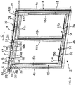
- the window 2 also comprises a motorized drive device 5 for slidingly moving an opening 3a relative to the fixed frame 4, as illustrated in figure 2 .
- the motorized drive device 5 is configured to slide only one of the first and second opening elements 3a, 3b relative to the fixed frame 4, in particular the first opening 3a.
- the second opening 3b is manually movable, in particular by the action of a user exerting a force on a handle, not shown, of the second opening 3b.
- the second opening 3b is fixed.
- the number of openings in the window is not limiting and may be different, in particular equal to one or three.
- Each opening 3a, 3b comprises a frame 15.
- Each opening 3a, 3b can also include at least one window 16 arranged in the frame 15.
- the number of panes of the opening is not limiting and may be different, in particular equal to two or more.
- the frame 15 of each opening 3a, 3b comprises an upper cross member 15a, a lower cross member 15b and first and second lateral uprights 15c, in an assembled configuration of the window 2 relative to the building, as illustrated in figures 1 and 2 .
- the first lateral upright 15c of the frame 15 of the first opening 3a is the lateral upright 15c located on the right of the first opening 3a, in the representation of figures 1 and 2 .
- the second side post 15c of the frame 15 of the first sash 3a is the side upright 15c located on the left of the first sash 3a, in the representation of figures 1 and 2 .
- the first lateral upright 15c of the frame 15 of the first opening 3a is opposed to the second lateral upright 15c of the frame 15 of the first opening 3a.
- the fixed frame 4 comprises an upper cross member 4a, a lower cross member 4b and first and second lateral uprights 4c, in the assembled configuration of the window 2 relative to the building, as illustrated in figures 1 and 2 .
- the first lateral upright 4c of the fixed frame 4 is the lateral upright 4c located on the right of the fixed frame 4, in the representation of figures 1 and 2 .
- the second lateral upright 4c of the fixed frame 4 is the lateral upright 4c located on the left of the fixed frame 4, in the representation of figures 1 and 2 .
- the first lateral upright 4c of the fixed frame 4 is opposed to the second lateral upright 4c of the fixed frame 4.
- the upper cross member 4a, the lower cross member 4b and the two lateral uprights 4c of the fixed frame 4 respectively have an inner face and at least one outer face.
- the inner faces of the upper cross member 4a, of the lower cross member 4b and of the two side uprights 4c of the fixed frame 4 are oriented towards the inside of the window 2 and, in particular, towards an outer edge of the frame 15 of each leaf 3a. , 3b.
- the outer faces of the upper cross member 4a, of the lower cross member 4b and of the two side uprights 4c of the fixed frame 4 are oriented towards the outside of the window 2.
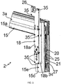
- the window 2 also comprises a fitting system 20 formed between the fixed frame 4 and each opening 3a, 3b, as illustrated in figure 3 .
- the fitting system 20 of the sliding window 2 makes it possible to slide each sash 3a, 3b relative to the fixed frame 4 in a sliding direction D, in the horizontal example, in the assembled configuration of the window 2 relative to the building , as shown in figures 1 and 2 .
- the upper cross member 4a of the fixed frame 4 comprises a first sliding rail, not shown, of the first opening 3a and a second sliding rail, not shown, of the second opening 3b.
- the lower cross member 4b of the fixed frame 4 comprises a first sliding rail 11a of the first opening 3a and a second sliding rail 11b of the second opening 3b.
- each of the upper 4a and lower 4b cross members of the fixed frame 4 comprises a first sliding rail 11a or equivalent of the first opening 3a and a second sliding rail 11b or equivalent of the second opening 3b.
- first and second openings 3a, 3b are configured to move respectively along the first and second sliding rails 11a, 11b and the like.
- first and second sliding rails 11a, 11b and the like are arranged parallel to one another.
- first and second sliding rails 11a, 11b and the like are offset with respect to each other along a thickness E of the fixed frame 4.
- the window 2 comprises sliding elements, not shown, allowing the movement of each leaf 3a, 3b relative to the fixed frame 4.
- the sliding elements are arranged at the level of the first and second sliding rails 11a, 11b of the lower cross member 4b.
- the sliding elements comprise rollers arranged under the first and second opening elements 3a, 3b.
- the casters are configured to roll on the first and second sliding rails 11a, 11b of the lower cross member 4b.
- An opening position by sliding, partial or maximum, of each opening 3a, 3b relative to the fixed frame 4 corresponds to a ventilation position of the building.
- the motorized drive device 5 makes it possible to automatically move the first leaf 3a by sliding relative to the fixed frame 4, in particular between the maximum opening position by sliding of the first leaf 3a relative to the fixed frame 4 and the closed position of the first sash 3a in relation to the fixed frame 4.
- the motorized drive device 5 comprises an electromechanical actuator 6.
- the electromechanical actuator 6 comprises an electric motor 7.
- the electromechanical actuator 6 can also include an output shaft 8.
- an axis of rotation X of the output shaft 8 is parallel to the sliding direction D of the first leaf 3a with respect to the fixed frame 4 and, in the present case, of the second leaf 3b with respect to the fixed frame 4.
- the window 2 comprises at least one locking device 21, 22 of the first opening 3a with respect to the fixed frame 4 in at least one locked position.
- the window 2 comprises two locking devices 21, 22 of the first opening 3a relative to the fixed frame 4 in two distinct locked positions.
- a first locked position of the first leaf 3a relative to the fixed frame 4 corresponds to a locked closed position of the first leaf 3a relative to the fixed frame 4, by means of a first locking device 21.
- the first locking device 21 is an integral part of the fitting system 20, as illustrated in figures 3 and 4 .
- the electromechanical actuator 6 is configured to drive the first leaf 3a in movement relative to the fixed frame 4 and to actuate the first locking device 21 in the locked closed position of the first leaf 3a relative to the fixed frame 4.
- a second locked position of the first opening 3a with respect to the fixed frame 4 corresponds to a locked ajar position of the first opening 3a with respect to the fixed frame 4, by means of a second locking device 22, shown in FIG. figure 2 .
- the locked ajar position is positioned between the closed position and an open position.
- the electromechanical actuator 6 is configured to drive the first leaf 3a in movement relative to the fixed frame 4 and to actuate the second locking device 22 in the half-open locked position of the first leaf 3a relative to the fixed frame 4.
- the first opening 3a can be locked relative to the fixed frame 4 in the closed position locked by means of the first locking device 21 or in the half-open position locked by means of the second locking device 22 or in each of the locked positions, closed and ajar, by means of the first and second locking devices 21, 22.
- the electric motor 7 of the electromechanical actuator 6 is of the variable speed type.
- the electric motor 7 of the electromechanical actuator 6 is configured to operate at at least one first speed setpoint V1 and at least one second speed setpoint V2.
- the second speed reference V2 is lower than the first speed reference V1.
- the displacement of the first leaf 3a relative to the frame dormant 4 is implemented either at a first speed or at a second speed.
- the electric motor 7 is of the electronically commutated brushless type, also called “BLDC” (acronym for the English term BrushLess Direct Current) or “synchronous with permanent magnets”.
- BLDC electronically commutated brushless type
- the electric motor 7 of the electromechanical actuator 6 is configured to adapt its speed of rotation as a function of the position of the first leaf 3a relative to the fixed frame 4.
- the electric motor 7 of the electromechanical actuator 6 is controlled at the second speed setpoint V2 when at least one end-of-travel position is reached, which can be, in particular, the closed position of the first opening 3a by relative to the fixed frame 4 and the fully open position of the first leaf 3a relative to the fixed frame 4, and, optionally, when at least one predetermined position is reached, which may be, in particular, the half-open locked position.
- the electric motor 7 of the electromechanical actuator 6 is configured to reduce its speed of rotation when at least one end-of-travel position or at least one predetermined position is reached.
- the electromechanical actuator 6 is placed on a part which is fixed relative to the window 2, in particular relative to the fixed frame 4.
- the electromechanical actuator 6 is of the reversible type.
- the electromechanical actuator 6 does not have a brake.
- the electromechanical actuator 6 can also include a reduction gear, not shown.
- the reducer comprises at least one reduction stage.
- Said at least one reduction stage may be an epicyclic type gear train.
- the type and number of reduction stages of the reducer are not limiting.
- the reducer is of the reversible type.
- the electromechanical actuator 6 comprises a clutch device.
- the device for disengaging the electromechanical actuator 6 makes it possible to separate the output shaft 8 from the electromechanical actuator 6 with respect to the electric motor 7 and, optionally, to the reduction gear.
- the disengaging device may be a mechanical transmission device, in particular a geared transmission device.
- the clutch device is configured to disengage a first pinion with respect to a second pinion.
- the first pinion is mounted on an arm.
- the arm is movable about an axis of rotation relative to the second pinion.
- the electric motor 7 and, optionally, the reduction gear are arranged inside a casing 17 of the electromechanical actuator 6.
- the electromechanical actuator 6 is of the tubular type.
- the electromechanical actuator 6 can also include an end-of-travel and / or obstacle detection device, not shown. This detection device is electronic.
- this detection device can be mechanical.
- the motorized drive device 5 also comprises a flexible element 9.
- the flexible element 9 is driven in movement by the electromechanical actuator 6.
- the flexible element 9 is configured to drive the first opening 3a in movement relative to the fixed frame 4, when the electromechanical actuator 6 is electrically activated.
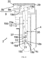
- the flexible element 9 comprises a first strand 9a and a second strand 9b, as illustrated in figure 4 .
- the flexible element 9 can be of circular section.
- the section of the flexible element is not limiting and may be different, in particular square, rectangular or even oval.
- the flexible element 9 is a cable or a cord.
- It can be made from a synthetic material, such as for example nylon or polyethylene of very high molar mass.
- the material of the flexible element is not limiting and may be different. In particular, it can be a steel.
- the motorized drive device 5 also comprises a drive arm 18 illustrated in figures 1 to 4 .
- the drive arm 18 is connected, on the one hand, to the frame 15 of the first opening 3a and, more particularly, to the first lateral upright 15c of the frame 15 of the first opening 3a and, on the other hand, to the flexible element 9.
- the drive arm 18 is configured to secure the flexible element 9 to the first opening 3a.
- the flexible element 9 is connected to the drive arm 18, regardless of the state of the locking elements of the fitting system 20, that is to say both in the locked state and in the unlocked state of the first leaf 3a in relation to the fixed frame 4.
- the flexible element 9 is permanently connected to the drive arm 18, in an assembled configuration of the motorized drive device 5 on the window 2.
- connection between the flexible element 9 and the drive arm 18 is simplified and makes it possible to minimize the costs of obtaining the window 2.
- the motorized drive device 5 comprises a winding pulley 19 of the flexible element 9.
- the winding pulley 19 is driven in rotation by the output shaft 8 of the electromechanical actuator 6.
- a first end of the first strand 9a of the flexible element 9 is connected to a first part of the winding pulley 19.
- a first end of the second strand 9b of the flexible element 9 is connected to a second part of the pulley d winding 19.
- first end of each of the first and second strands 9a, 9b of the flexible element 9 is hooked respectively to the first part or to the second part of the winding pulley 19 by means of fixing elements, not shown. .
- each of the first and second strands 9a, 9b of the flexible element 9 is respectively fixed directly to the first part or to the second part of the winding pulley 19.
- the elements for fixing the end of each of the first and second strands 9a, 9b of the flexible element 9 are elements of the cable clamp type.
- these fixing elements are screws, in particular of the self-tapping type, screwed into the winding pulley 19, so as to fix the first and second strands 9a, 9b of the flexible element 9 by wedging between the screw head and the winding surface of the flexible element 9 of the winding pulley 19.
- the direction of winding, respectively of unwinding, of the first strand 9a of the flexible element 9 around the first part of the winding pulley 19 is opposite to the direction of winding, respectively of unwinding, of the second strand 9b of the flexible element 9 around the second part of the winding pulley 19.
- the first strand 9a of the flexible element 9 wraps around the first part of the winding pulley 19, while the second strand 9b of the flexible element 9 unwinds around the second part of the winding pulley 19.
- the second sliding direction of the first opening 3a relative to the fixed frame 4 is opposite to the first sliding direction.
- the direction of sliding of the first leaf 3a relative to the fixed frame 4 is determined as a function of the direction of rotation of the output shaft 8 of the electromechanical actuator 6.
- the direction of rotation of the drive. Winding pulley 19 is determined by the direction of rotation of the output shaft 8 of the electromechanical actuator 6.
- the direction of drive in rotation of the first strand 9a and of the second strand 9b of the flexible element 9 around the first and second parts of the winding pulley 19 is a function of the direction of rotation of the output shaft 8. of the electromechanical actuator 6.
- the direction of rotation of the winding pulley 19 is identical to the direction of rotation of the output shaft 8 of the electromechanical actuator 6.
- Control means of the electromechanical actuator 6 allow the movement by sliding of the first leaf 3a relative to the fixed frame 4.
- These control means comprise at least one electronic control unit 10.
- the electronic control unit 10 is configured for start the electric motor 7 of the electromechanical actuator 6 and, in particular, allow the supply of electric energy to the electric motor 7.
- the electronic control unit 10 controls, in particular, the electric motor 7, so as to open or close by sliding the first opening 3a relative to the fixed frame 4.
- the window 2 comprises the electronic control unit 10. More particularly, the electronic control unit 10 is integrated in the motorized drive device 5 and, more particularly, in the electromechanical actuator 6.
- the control means of the electromechanical actuator 6 and, more particularly, the electronic control unit 10 comprise hardware and / or software means.
- the hardware means can comprise at least one microcontroller 36.
- the motorized drive device 5 and, more particularly, the electromechanical actuator 6 comprises a counting device 24.
- the counting device 24 comprises at least one sensor 32, in particular of position.
- the counting device 24 is configured to cooperate with the electronic control unit 10. Furthermore, the counting device 24 and the electronic control unit 10 are configured to determine a position, which can be called "current", of the first. opening 3a in relation to the fixed frame 4.
- the electronic control unit 10 is configured to monitor at least one signal S coming from the counting device 24 at a predetermined frequency F as a function of the position of the first leaf 3a relative to the fixed frame 4.
- the counting device 24 comprises two sensors.
- the number of sensors of the counting device is not limiting and may be different, in particular one or greater than or equal to three.
- the counting device 24 is of the magnetic type, for example an encoder equipped with one or more Hall effect sensors.
- the counting device 24 makes it possible to determine the number of revolutions made by a rotor of the electric motor 7.
- the counting device 24 makes it possible to determine the number of revolutions made by the output shaft 8 of the electromechanical actuator 6.
- the type of counting device is not limiting and may be different, in particular of the optical type, for example an encoder equipped with one or more optical sensors.
- the electronic control unit 10 and, more particularly, the microcontroller 36 of the electronic control unit 10 comprises at least one memory configured to store the current position of the first leaf 3a with respect to the fixed frame 4 determined by means of the counting device 24.
- the memory of the electronic control unit 10 is also configured to store at least one end-of-travel position, which may be, in particular, the closed position of the first leaf 3a relative to the fixed frame 4 or the fully open position of the first opening 3a relative to the fixed frame 4, and, optionally, at least one predetermined position, which can be, in particular, the half-open locked position of the first opening 3a relative to the fixed frame 4.
- the electronic control unit 10 and the counting device 24 are configured to determine the position of the first leaf 3a relative to the fixed frame 4 as a function of one or more last control commands previously executed by the electronic control unit. control 10.
- the electronic control unit 10 comprises a rechargeable energy reserve 38.
- the rechargeable energy reserve 38 of the electronic control unit 10 is configured to guarantee the monitoring of the signal S coming from the counting device 24 for a predetermined duration T, which can also be called the discharge duration, during which the supply of electrical energy to the motorized drive device 5 and, more particularly, to the electromechanical actuator 6 and to the electronic control unit 10 is cut off.
- the predetermined duration T is of the order of thirty seconds.
- the rechargeable energy reserve 38 of the electronic control unit 10 is a capacitor.
- the capacitor is mounted on an electronic card 39 of the electronic control unit 10.
- the motorized drive device 5 is a sub-assembly pre-assembled before assembly, in the example inside a box 30, which comprises at least the electromechanical actuator 6, the winding pulley 19. , the flexible element 9 and the electronic control unit 10.
- the second locking device 22 is also mounted inside the box 30 and, more particularly, fixed inside the box 30, in particular on a wall 29 of the box 30, by means of fixing elements, not shown, which may be, for example, elements for fixing by screwing or riveting.
- the motorized drive device 5 is controlled by a control unit.
- the control unit can be, for example, a local control unit 12.
- the local control unit 12 can be wired or wirelessly connected to a central control unit 13.
- the central control unit 13 controls the local control unit 12, as well as other similar local control units. and distributed throughout the building.
- the electronic control unit 10 also comprises a communication module 23, in particular for receiving control orders, the control orders being sent by a command transmitter, such as the local control unit 12 or the central control unit 13, these orders being intended to control the motorized drive device 5.
- a command transmitter such as the local control unit 12 or the central control unit 13
- the communication module 23 of the electronic control unit 10 is of the wireless type.
- the control orders can be, for example, radio orders.
- the communication module 23 can also allow the reception of orders transmitted by wired means.
- the electronic control unit 10, the local control unit 12 and / or the central control unit 13 can be in communication with one or more sensors configured to determine, for example, a temperature, a humidity, a speed of wind, a measurement of an indoor or outdoor air quality parameter or even a presence.
- the local control unit 12 and / or the central control unit 13 can also be in communication with a server 14, so as to control the electromechanical actuator 6 according to data made available remotely by means of a communication network, in particular an internet network which can be connected to the server 14.
- a communication network in particular an internet network which can be connected to the server 14.
- the electronic control unit 10 can be controlled from the local control unit 12.
- the local control unit 12 is provided with a control keyboard.
- the control keyboard of the local control unit 12 comprises selection elements and, optionally, display elements.
- the selection elements can be pushbuttons or sensitive keys
- the display elements can be light-emitting diodes
- an LCD display (acronym for the English term “Liquid Crystal Display”) or TFT (acronym of the Anglo-Saxon term “Thin Film Transistor”).
- the Selection and display elements can also be achieved by means of a touch screen.
- the local control unit 12 can be a fixed or nomadic control point.
- a fixed control point corresponds to a control box intended to be fixed on a facade of a building wall, on one face of the frame 15 of the first sash 3a of the window 2 or else on one face of the fixed frame 4 of the window 2.
- a nomadic control point corresponds to a remote control.
- the local control unit 12 makes it possible to directly control the electronic control unit 10 according to a selection made by the user.
- the local control unit 12 allows the user to intervene directly on the electromechanical actuator 6 of the motorized drive device 5 via the electronic control unit 10 associated with this motorized drive device 5 , or to intervene indirectly on the electromechanical actuator 6 of the motorized drive device 5 via the central control unit 13.
- the motorized drive device 5 in particular the electronic control unit 10, is preferably configured to execute control commands for closing by sliding as well as opening by sliding of the first leaf 3a with respect to the fixed frame. 4, these control orders being able to be issued, in particular, by the local control unit 12 or by the central control unit 13.
- the electronic control unit 10 is thus able to put into operation the electromechanical actuator 6 of the motorized drive device 5 and, in particular, allow the supply of electrical energy to the electromechanical actuator 6.
- the electronic control unit 10 is placed inside the casing 17 of the electromechanical actuator 6.
- the local control unit 12 comprises a sensor measuring at least one parameter of the environment inside the building and integrated into this unit.
- the local control unit 12 can communicate with the central control unit 13, and the central control unit 13 can control the electronic control unit 10 associated with the motorized drive device 5 according to data coming from of the sensor measuring the parameter of the environment inside the building.
- the local control unit 12 can directly control the electronic control unit 10 associated with the motorized drive device 5 as a function of data coming from the sensor measuring the parameter of the environment inside. of the building.
- a parameter of the environment inside the building measured by the sensor integrated into the local control unit 12 is the humidity, the temperature, the carbon dioxide level or the rate. of a volatile organic compound in the air.
- the activation of the local control unit 12 by the user has priority over the activation of the central control unit 13, so as to control the closing and opening by sliding of the first leaf 3a. in relation to the fixed frame 4.
- the activation of the local control unit 12 directly controls the electronic control unit 10 associated with the motorized drive device 5 according to a selection made by the user, possibly by inhibiting a control command that can be emitted by the central control unit 13 or by ignoring a value measured by a sensor measuring at least one parameter of the environment inside the building or outside the building, or a presence detection signal at inside the building.
- the motorized drive device 5 can be controlled by the user, for example by receiving a control command corresponding to pressing a selection element of the local control unit 12, such as a remote control or a fixed control point.
- the motorized drive device 5 can also be controlled automatically, for example by receiving a control command corresponding to at least one signal originating from at least one sensor and / or to a signal originating from a clock.
- the sensor and / or the clock can be integrated into the local control unit 12 or into the central control unit 13.
- the motorized drive device 5 makes it possible to automatically move the first leaf 3a by sliding relative to the fixed frame 4 to a predetermined position, between the closed position and the maximum open position.
- the sliding movement of the first leaf 3a relative to the fixed frame 4 to the predetermined position, in particular partial opening or closing, is implemented following receipt of a control command issued by the unit. local control unit 12, the central control unit 13 or a sensor.
- a sliding movement of the first leaf 3 relative to the fixed frame 4 in the sliding direction D is implemented by supplying electrical energy to the electromechanical actuator 6, so as to unwind or wind the first and second strands 9a, 9b of the flexible element 9 around the first and second parts of the winding pulley 19.
- the unwinding or winding of the first and second strands 9a, 9b of the flexible element 9 around the first and second parts of the winding pulley 19 is controlled by the supply of electrical energy to the electromechanical actuator 6. .
- the electrical energy supply to the electromechanical actuator 6 is controlled by a control command received by the electronic control unit 10 from the local control unit 12, from the central control unit 13 or of a sensor.
- the motorized drive device 5, in particular the electromechanical actuator 6, is supplied with electrical energy from a mains electricity supply network, in particular by the commercial AC network.
- the electromechanical actuator 6 comprises an electrical supply cable, not shown, allowing it to be supplied with electrical energy from the mains electrical supply network.
- the motorized drive device 5, in particular the electromechanical actuator 6, is supplied with electrical energy by means of a battery, not shown.
- the battery can be recharged, for example, by a photovoltaic panel or any other energy recovery system, in particular of the thermal type.
- the motorized drive device 5, in particular the electromechanical actuator 6, is supplied with electrical energy by means of the battery or from the mains electricity supply network, in particular according to the state of charge. drums.
- the winding pulley 19 and the output shaft 8 of the electromechanical actuator 6 have the same axis of rotation X.
- the axis of rotation of the winding pulley 19 coincides with the axis of rotation X of the output shaft 8 of the electromechanical actuator 6.
- the winding pulley 19 is arranged in the extension of the output shaft 8 of the electromechanical actuator 6 and is driven in rotation about the same axis of rotation X as the output shaft 8 of the electromechanical actuator 6.
- the flexible element 9 is in the form of a so-called open loop, at least between the first end of the first strand 9a connected to the first part of the winding pulley 19 and the first end of the second strand. 9b connected to the second part of the winding pulley 19.
- first and second strands 9a, 9b of the flexible element 9 are connected to the winding pulley 19 and separated at the first and second parts thereof.
- the electromechanical actuator 6 is fixed inside the box 30 by means of fixing elements 28, as illustrated in figure 2 .
- winding pulley 19 is held inside the box 30 by means of these same fasteners 28.
- the fixing elements 28 of the electromechanical actuator 6 inside the box 30 comprise supports, in particular fixing brackets.
- these supports 28 are fixed to the wall 29 of the box 30 by screwing.
- each support 28 comprises at least one passage hole, not shown, for a fixing screw.
- each support 28 may include two holes for passing a fixing screw.
- a fixing screw passing through a passage hole is screwed into the wall 29 of the box 30, in particular into a screw opening made in the wall 29 of the box 30.
- the fixing elements 28 of the electromechanical actuator 6 inside the box 30 comprise three supports.
- a first support 28 is assembled at a first end 6a of the electromechanical actuator 6.
- a second support 28 is assembled at a second end 6b of the electromechanical actuator 6 and, more particularly, between the second end 6b of the electromechanical actuator. 6 and a first end 19a of the winding pulley 19.
- the first end 6a of the electromechanical actuator 6 is opposite the second end 6b of the electromechanical actuator 6.
- a third support 28 is assembled at a second end 19b of the winding pulley 19.
- the first end 19a of the winding pulley 19 is opposite the second end 19b of the winding pulley 19.
- each support 28 comprises at least one pin configured to cooperate with a groove formed in the wall 29 of the box 30.
- each support 28 comprises two pins.
- each support 28 is oriented and positioned relative to the wall 29 of the box 30.
- the fixing of the electromechanical actuator 6, as well as of the winding pulley 19, on the supports 28 is implemented by fixing elements, in particular by screwing.
- the fixing elements of the electromechanical actuator 6, as well as of the winding pulley 19, on the supports 28 are elastic snap fastening elements.
- the flexible element 9 of the motorized drive device 5 extends inside the box 30, from the first part of the winding pulley 19 to the second part of the winding pulley 19 .
- the motorized drive device 5 comprises at least one angle transmission element, not shown, configured to cooperate with the flexible element 9, which may be, for example, a pulley or a guide element.
- the number of angle transmission elements is not limitative.
- the angular transmission element is a pulley
- the latter can be produced, for example, by an idler pulley, in other words mounted freely in rotation, in particular with respect to a wall of the box 30, or by a fixed pulley, in other words integral with its axis, in particular fixed relative to a wall of the box 30.
- the electromechanical actuator 6 and the flexible element 9 are arranged in the box 30 formed in the upper part of the window 2, in particular extending at least in part above the upper cross member 4a of the fixed frame 4.
- winding pulley 19 is placed in the box 30 provided in the upper part of the window 2.
- box 30 extends completely in front of the fixed frame 4, in the assembled configuration of the window 2 with respect to the building.
- the safe 30 is arranged opposite the upper cross member 4a of the fixed frame 4, that is to say in the prominence towards the interior of the building, in the assembled configuration of the window 2 relative to the building.
- the box 30 extends partially in front of the fixed frame 4, in the assembled configuration of the window 2 with respect to the building.
- the box 30 extends in part projecting from the fixed frame 4.
- the box 30 is above the upper cross member 4a of the frame. sleeper 4 and facing this upper cross member 4a, that is to say in prominence towards the interior of the building, in the assembled configuration of the window 2 with respect to the building.
- the box 30 comprises a fixed part 30a and a removable part 30b, so as to allow access to the electromechanical actuator 6 and to the flexible element 9, as well as to the winding pulley 19.
- the removable part 30b of the box 30 makes it possible to carry out a maintenance operation on the motorized drive device 5 and / or a repair operation thereof.
- the latter can be moved by the user independently of the first opening 3a, in particular in the event of an absence of electrical energy supply to the motorized drive device 5 or motorized drive device failure 5.
- the motorized drive device 5 makes it possible to automatically slide the first leaf 3a relative to the fixed frame 4 in the sliding direction D, by winding, respectively unwinding, the first strand 9a of the flexible element 9 around the first part of the winding pulley 19 and unwinding, respectively winding, the second strand 9b of the flexible element 9 around the second part of the winding pulley 19.
- the motorized drive device 5 makes it possible to close and open in a motorized manner the first leaf 3a relative to the fixed frame 4, by sliding in the sliding direction D.
- Such a manual movement of the first opening 3a relative to the fixed frame 4 can also be implemented following the separation of the flexible element 9 from the first opening 3a or following the separation of the drive arm 18. relative to the first sash 3a.
- the use of the flexible element 9 to move the first opening 3a relative to the fixed frame 4 makes it possible to minimize the costs of obtaining the motorized drive device 5, as well as to minimize the size of the device. motorized drive 5, in particular with respect to a belt.
- the window 2 comprises a covering element 31, as illustrated in figures 1 and 2 .
- the covering element 31 is configured to cover at least the drive arm 18 and, optionally, at least part of the first lateral upright 15c of the frame 15 of the first opening 3a, in particular according to the height of the frame 15, in the assembled configuration of window 2 relative to the building.
- the covering element 31 is fixed relative to the first opening 3a by means of fixing elements, not shown, following the assembly of the drive arm 18 on the frame 15 of the first opening 3a.
- the fixing elements of the covering element 31 are configured to cooperate with the drive arm 18 and / or with the first lateral upright 15c of the frame 15 of the first opening 3a.
- the elements for fixing the covering element 31 relative to the first leaf 3a can be, in particular, elements for fixing by elastic snap-fastening or by screwing.
- the drive arm 18 comprises a cover 18a and a body 18b, as illustrated in figure 3 .
- the cover 18a is configured to cover the body 18b of the drive arm 18.
- the cover 18a is fixed to the body 18b of the drive arm 18 by means of fixing elements 35, in an assembled configuration of the drive arm 18.
- the fixing of the cover 18a on the body 18b of the drive arm 18 is implemented by screwing.
- the cover 18a comprises passage holes, not shown, configured to cooperate with fixing screws 35.
- the body 18b of the drive arm 18 comprises fixing holes 18d configured to cooperate with the fixing screws 35, as shown in figure 4 .
- the window 2 also comprises a locking control device 26 of the first locking device 21, as illustrated in figures 3 and 4 .
- the locking control device 26 is configured, on the one hand, to cooperate with the first locking device 21 and, on the other hand, to be actuated by means of the flexible element 9, when the actuator electromechanical 6 is electrically activated.
- the drive arm 18 supports the locking control device 26.
- the drive arm 18 and the locking control device 26 form an integral mechanical sub-assembly.
- the locking control device 26 is disposed in part inside the drive arm 18 and, in particular, outside the frame 15 of the first opening 3a.
- the locking control device 26 is concealed behind the drive arm 18, so as to improve the aesthetic appearance of the window 2.
- the drive arm 18 covers the locking control device 26, like a cover, so as to hide the various elements making up the latter and to improve the aesthetics of the window 2.
- the drive arm 18 is connected to the flexible element 9 via the locking control device 26.
- the box 30 comprises a slot, not shown and configured to allow the passage of an upper part of the drive arm 18 and / or of the locking control device 26, during a movement of the first opening 3a relative to to the fixed frame 4 in the sliding direction D.
- the drive arm 18 and the locking control device 26 can be driven to move along the box 30, in particular at least partially facing an outer face of the box 30 oriented towards the side. inside the building, in the assembled configuration of the window 2 with respect to the building, while being connected to the flexible element 9.
- the upper part of the drive arm 18 and / or the upper part of the locking control device 26 are configured to move inside the slot made in the trunk 30.
- the slot in the safe 30 is provided in a lower face of the safe 30, in the assembled configuration of the window 2 with respect to the building.
- a lower part of the drive arm 18 and a lower part of the locking control device 26 are arranged outside the trunk 30.
- the arrangement formed by the motorized drive device 5, the fitting system 20 and the locking control device 26 of the window 2 makes it possible to dispense with a handle for operating the first leaf 3a, generally arranged halfway up the window 2.
- the first opening 3a can be moved only by means of the motorized drive device 5 following receipt of a control command by the electronic control unit 10 coming from one of the control units 12, 13.
- the fitting system 20 is now described in more detail.
- the fitting system 20 also comprises a lock, not shown, and at least one locking element, not shown, of the first opening 3a with respect to the fixed frame 4.
- the fitting system 20 is mounted along the first lateral upright 15c of the frame 15 of the first opening 3a.
- the cremone bolt is placed inside the first lateral upright 15c of the frame 15 of the first opening 3a.
- the cremone bolt can also be placed in part inside the upper cross member 15a or the lower cross member 15b of the frame 15 of the first opening 3a.
- the lock comprises at least one rod.
- the lock also includes a body.
- the body of the lock is fixed relative to the first lateral upright 15c of the frame 15 of the first opening 3a.
- the rod is configured to move relative to the body of the lock.
- the rod is made in several parts connected together, in particular by means of retaining elements.
- the movement of the rod of the lock is implemented along the first lateral upright 15c of the frame 15 of the first opening 3a, in particular in a vertical direction, in the assembled configuration of the window 2 with respect to the building.
- the rod of the lock comprises at least one hook, not shown, forming a locking element of the first opening 3a with respect to the fixed frame 4, as mentioned above, and, preferably, a plurality of hooks.
- the fixed frame 4, in particular the first lateral upright 4c of the fixed frame 4, comprises at least one keeper, not shown, and, preferably, a plurality of keeps.
- Each hook of the rod is configured to cooperate with a keeper of the fixed frame 4.
- the first leaf 3a is in a closed and locked position with respect to the fixed frame 4.
- the first leaf 3a is in an unlocked position with respect to the fixed frame 4, this unlocked position being able to be further closed or open.
- the first locking device 21 is arranged inside the frame 15 of the first opening 3a and, more particularly, inside the first lateral upright 15c of the frame 15 of the first opening 3a.
- the first locking device 21 comprises at least one housing 37, as illustrated in figure 4 , a tree 33, commonly called a "square" and illustrated on figure 4 , a drive bell, not shown, and at least one bolt 25, as illustrated in figure 3 .
- the first locking device 21 comprises two bolts 25.
- the drive bell comprises a housing.
- a first end of the shaft 33 is disposed inside the housing of the drive bell.
- each bolt 25 of the first locking device 21 is configured to cooperate with a hole made in the rod of the lock.
- the drive bell is rotated inside the housing 37 of the first locking device 21, then each bolt 25 of the first locking device 21 is driven in translation, so in moving the rod along the first lateral upright 15c of the frame 15 of the first opening 3a, in particular in a vertical direction, in the assembled configuration of the window 2 with respect to the building.
- the first locking device 21 has screw holes, not shown, and a housing, not shown, configured to receive the drive bell as well as the shaft 33, similar to those of a lock of a handle. standard manual, in particular with regard to their location and dimensioning.
- a standard manual handle can be arranged as a replacement for the drive arm 18, so as to manually close and lock the first opening 3a with respect to the fixed frame 4.
- the drive arm 18 can be replaced by a standard manual handle, so as to manually moving the first leaf 3a relative to the fixed frame 4 and manually locking the first leaf 3a relative to the fixed frame 4 by actuating the first locking device 21.
- the fitting system 20 can also include an anti-mishandling system 27, as illustrated on figure 3 .
- the locking control device 26 actuates the first locking device 21.
- window 2 makes it possible to lock and unlock the first leaf 3a with respect to the fixed frame 4 by means of the fitting system 20, when the closed position of the first leaf is reached. 3a with respect to the fixed frame 4, while maintaining the traditional techniques for installing windows, in particular for adjusting the fitting systems.
- this arrangement of the window 2 makes it possible to use a fitting system comprising standard elements, in particular the first locking device 21 having standard characteristics.
- first locking device 21 is associated with the drive arm 18 via the locking control device 26, so as to secure the first opening 3a to the motorized drive device 5 provided with the flexible element.
- the movement transmitted by the motorized drive device 5 along the sliding direction D is transformed into a rotational movement at the level of the first locking device 21 via the locking control device 26.
- the first strand 9a of the flexible element 9 comprises a second end connected to the locking control device 26.
- the second strand 9b of the flexible element 9 comprises a second end connected to the locking control device 26.
- the second end of the first strand 9a of the flexible element 9 is opposite the first end of the first strand 9a of the flexible element 9 connected to the first part of the winding pulley 19.
- the second end of the second strand 9b of the flexible element 9 is opposite the first end of the second strand 9b of the flexible element 9 connected to the second part of the winding pulley 19.
- the flexible element 9 is made in two parts.
- the first part of the flexible element 9 is formed by the first strand 9a extending between the first part of the winding pulley 19 and the locking control device 26.
- the second part of the flexible member 9 is formed by the second strand 9b extending between the second part of the winding pulley 19 and the locking control device 26.
- the anti-false maneuver system 27 comprises a retractable pin 34.
- the retractable pin 34 is configured to be moved between a rest position, in which the locking gear is blocked, and an activated position, in which the locking gear is released.
- the anti-mishandling system 27 is activated when the retractable pin 34 is driven inside a housing, not shown, provided in the frame 15 of the first opening 3a.
- the insertion of the retractable pin 34 in the aforementioned housing is implemented by the resting of the retractable pin 34 against the fixed frame 4, in particular the first lateral upright 4c of the fixed frame 4, that is to say - say when the first leaf 3a is in the closed position relative to the fixed frame 4.
- the rod of the gear is configured to move relative to the body of the gear between a first position, called the unlocking position of the first opening 3a relative to the frame frame 4, and a second position, called the locking of the first leaf 3a relative to the frame 4, and vice versa.
- the anti-mishandling system 27 is configured to prevent movement of the rod of the locking gear relative to the body of the locking mechanism, between its unlocking position and its locking position, as long as the retractable pin 34 is held in its position. rest position.
- the retractable pin 34 extends in a direction perpendicular to the cremone bolt.
- the fitting system 20 can be devoid of the anti-mishandling system 27.
- the drive arm 18 and the first locking device 21 are arranged in the upper part of the first lateral upright 15c of the frame 15 of the first opening 3a, in the assembled configuration of the window 2 with respect to the building.
- the drive arm 18 is configured to hook onto the flexible element 9 arranged above the fixed frame 4, in particular the upper cross member 4a of the fixed frame 4.
- the drive arm 18 and the first locking device 21 are arranged closest to the flexible element 9, since the flexible element 9 extends along the upper cross member 4a of the fixed frame 4.
- the drive arm 18 is fixed, and therefore immobile, relative to the frame 15 of the first opening 3a.
- connection between the drive arm 18 and the frame 15 of the first leaf 3a is simplified and makes it possible to minimize the costs of obtaining the window 2.
- the method for controlling the motorized drive device 5 in operation comprises a monitoring step E20, by means of the electronic control unit 10, of the signal S coming from the counting device 24 at the predetermined frequency F as a function of the position of the first leaf 3a relative to the fixed frame 4.
- the predetermined frequency F has at least a first value F1.
- the predetermined frequency F has a zero value or a second value F2, the second value F2 of the predetermined frequency F being less than the predetermined frequency F.
- first value F1 of the predetermined frequency F is a monitoring step E20, by means of the electronic control unit 10, of the signal S coming from the counting device 24 at the predetermined frequency F as a function of the position of the first leaf 3a relative to the fixed frame 4.
- the predetermined frequency F has at least a first value F1.
- the predetermined frequency F has a zero value or a second value F2, the second value F2 of the predetermined frequency F being less than the predetermined frequency F.
- the motorized drive device 5 makes it possible to determine a current position of the first sash 3a relative to the fixed frame 4, by means of the counting device 24 and of the electronic control unit 10, during a movement of the first. opening 3a with respect to the fixed frame 4, implemented either by means of the motorized drive device 5 or manually by the user, that is to say without electrically activating the electromechanical actuator 6, while ensuring safety of the user, in particular when reaching an end-of-travel position, which may be, in particular, the closed position of the first leaf 3a with respect to the fixed frame 4 or the fully open position of the first leaf 3a with respect to to the fixed frame 4, or to a predetermined position, which may be, in particular, the half-open locked position of the first leaf 3a relative to the fixed frame 4, and by limiting a electrical energy consumption of the motorized drive device 5.
- the counting device 24 and the electronic control unit 10 are configured to determine a position of the first sash 3a with respect to the fixed frame 4 at any time, by means of the sensor (s) 32 of the counting device. 24, so as to guarantee the safety of the user.
- the monitoring of the signal S coming from the counting device 24 by the electronic control unit 10 is implemented according to the first value F1 of the predetermined frequency F.
- the monitoring of the signal S coming from the counting device 24 by the electronic control unit 10 is either deactivated, that is to say that the predetermined frequency F for monitoring the signal S coming from the counting device 24 by the electronic control unit 10 is zero, or implemented according to the second value F2 of the predetermined frequency F.
- the first value F1 of the predetermined frequency F is dependent on a frequency of the microcontroller of the electronic control unit 10, in particular of a clock of the microcontroller, and, more particularly, corresponds to a frequency of the microcontroller.
- the first value F1 of the predetermined frequency F is independent of the frequency of the microcontroller.
- the first value F1 of the predetermined frequency F may be of the order of 100 kilohertz.
- the second value F2 of the frequency F predetermined may be of the order of one Hertz.
- the electronic control unit 10 is informed of a change of state of the counting device 24 and, more particularly, of the one of the sensors 32 of the counting device 24, as a function of the first value F1 of the predetermined frequency F.
- the counting device 24 and, more particularly, the sensors 32 are continuously supplied with electrical energy.
- the electronic control unit 10 determines a change of state of the counting device 24 and, more particularly, of one of the sensors 32 of the counting device 24, as a function of the second value F2 of the predetermined frequency F.
- the counting device 24 and, more particularly, the sensors 32 are supplied with electrical energy periodically, in particular according to the second value F2 of the predetermined frequency F.
- the method comprises a step of determining the position E10 of the first opening 3a relative to the fixed frame 4.
- the monitoring step E20 is implemented as a function of the determined position of the first leaf 3a relative to the fixed frame 4.
- the monitoring step E20 is implemented according to the first value F1 of the predetermined frequency F.
- the monitoring step E20 is either temporarily inhibited, in particular by temporarily interrupting the monitoring of the signal S coming from the counting device. 24, or implemented according to the second value F2 of the predetermined frequency F.
- step E10 of determining the position of the first opening 3a relative to the fixed frame 4 is implemented by means of the electronic control unit 10 and the counting device 24.
- the method comprises a step of determining a manual displacement E30 of the first leaf 3a relative to the fixed frame 4.
- the step of determining a manual displacement E30 is implemented, on the one hand, when the first leaf 3a is positioned outside the locked position relative to the fixed frame 4 and, on the other hand, when the first sash 3a is positioned in the locked position relative to the fixed frame 4.
- the step of determining a manual displacement E30 of the first leaf 3a relative to the fixed frame 4 is implemented by means of the electronic control unit 10 and the counting device 24.
- the method comprises a step of determining the direction of manual movement E40 of the first leaf. 3a in relation to the fixed frame 4.
- the step of determining the direction of manual movement E40 of the first leaf 3a relative to the fixed frame 4 is implemented by means of the electronic control unit 10 and the counting device 24.
- the method comprises a first step E50 for resetting the position of the first leaf 3a with respect to the fixed frame 4 by the counting device 24 and the electronic control unit 10.
- the method implements the first step of resetting E50 of the position of the first leaf 3a relative to the fixed frame 4.
- the first resetting step E50 corresponds to a detection of the closed position of the first leaf 3a relative to the fixed frame 4 and, optionally, the fully open position of the first sash 3a in relation to the fixed frame 4.
- the first resetting step E50 corresponds to detection of the locked half-open position.
- the first resetting step E50 is implemented by means of the electronic control unit 10 and the counting device 24.
- the first resetting step E50 is implemented by controlling the electric motor 7 of the electromechanical actuator 6 according to the second speed setpoint V2.
- the electric motor 7 of the electromechanical actuator 6 is controlled at a reduced speed setpoint relative to a nominal speed setpoint of the electric motor 7, so as to protect the window 2 and, more particularly, the motorized drive device 5.
- the first resetting step E50 can be implemented following the step of determining a manual displacement E30 or following the step of determining the direction of manual displacement E40.
- the method again implements the step of determining a manual displacement E30 of the first leaf 3a relative to the fixed frame 4, which is shown in figure 5 .
- the first resetting step E50 is particularly advantageous in the case where the predetermined frequency F for monitoring the signal S coming from the counting device 24 by the electronic control unit 10 is zero.
- the method comprises a first E60 drive step of the first opening 3a relative to the fixed frame 4 by means of the motorized drive device 5, in other words by the electrical activation of the electromechanical actuator 6.
- the method can implement the first resetting step E50 then the first training step E60, as shown in figure 5 , Or vice versa.
- the first drive step E60 of the first opening 3a relative to the fixed frame 4 is implemented in the opposite direction of movement with respect to the direction of movement of the first opening 3a relative to the determined fixed frame 4, during the 'step for determining the direction of manual movement E40.
- the first drive step E60 is implemented following the step of determining the direction of manual movement E40.
- the method can implement the first drive step E60 of the first opening 3a relative to the fixed frame 4 in combination with the monitoring step E20 according to the first value F1 of the predetermined frequency F.
- the method again implements the step of determining the position E10 of the first leaf 3a with respect to the fixed frame 4.
- the method makes it possible to determine the current position of the first leaf 3a relative to the fixed frame 4, during the movement of the first leaf 3a relative to the fixed frame 4 by means of the motorized drive device 5.
- the first drive step E60 is implemented by controlling the electric motor 7 of the electromechanical actuator 6 according to the first speed setpoint V1.
- the electric motor 7 of the electromechanical actuator 6 is controlled at a nominal speed setpoint of the electric motor 7, so as to reach the locked position, in particular closed, as quickly as possible. possible.
- the method comprises a step of E70 triggering of an alarm signal A.
- the triggering step E70 of an alarm signal A is implemented by means of the electronic control unit 10.
- the method can implement the triggering step E70 of an alarm signal A in combination with at least the first resetting step E50 or the first training step E60.
- the alarm signal A is emitted by means of a device alarm, not shown, receiving a message from the means of the communication module 23 of the electronic control unit 10.
- the alarm signal A is emitted by means of the motorized drive device 5 and, more particularly, of the electromechanical actuator 6 configured to emit the alarm signal A, which may be, in particular, audible or vibratory.
- the monitoring step E20 is implemented according to a third value F3 of the predetermined frequency F.
- the third value F3 of the predetermined frequency F is greater than the first value F1 of the predetermined frequency F.
- the monitoring step E20 is also implemented as a function of the determined type of movement of the first leaf 3a relative to the fixed frame 4, either manual or motorized.
- the increase in the predetermined frequency F of monitoring the signal S coming from the counting device 24 is particularly advantageous since the speed of a manual movement of the first leaf 3a relative to the fixed frame 4 can be greater than the speed of a movement of the first leaf 3a relative to the fixed frame 4 implemented by the motorized drive device 5.
- the method again implements the step of determining the position E10 of the first leaf 3a with respect to the fixed frame 4 .
- the method makes it possible to determine whether the first leaf 3a is positioned in the locked, closed or ajar position, with respect to the fixed frame 4, following the determined manual movement, during the step of determining a manual movement E30.
- the method comprises a second step E80 for driving the first leaf 3a relative to the frame 4 by means of the motorized drive device 5, in other words by the electrical activation of the electromechanical actuator 6.
- the method can implement the second drive step E80 of the first opening 3a relative to the fixed frame 4 in combination with the monitoring step E20 according to the third value F3 of the predetermined frequency F.
- the second drive step E80 of the first opening 3a relative to the fixed frame 4 is implemented in the same direction of movement as the direction of movement of the first leaf 3a relative to the determined fixed frame 4, during the step for determining the direction of manual movement E40.
- the implementation of the second drive step E80 of the first sash 3a relative to the fixed frame 4 in the same direction of movement of the first sash 3a relative to the determined fixed frame 4, during the step of determining the direction of manual movement E40, makes it possible to accompany the movement of the first leaf 3a relative to the fixed frame 4 by means of the motorized drive device 5, as well as to facilitate the handling of the first leaf 3a relative to the fixed frame 4 by the 'user.
- such an implementation of the second drive step E80 of the first leaf 3a relative to the fixed frame 4 makes it possible to provide a function of assisting a movement of the first leaf 3a relative to the fixed frame 4, by by means of the motorized drive device 5, in particular in the case where only part of a displacement force of the first leaf 3a relative to the fixed frame 4 is produced by the motorized drive device 5.
- the second training step E80 is implemented following the step of determining the direction of manual movement E40.
- the method again implements the step of determining the position E10 of the first opening 3a with respect to the fixed frame 4.
- the method makes it possible to determine whether or not the first sash 3a reaches the locked, closed or ajar position, relative to the fixed frame 4, during the movement of the first sash 3a relative to the fixed frame 4 by means of the drive device. motorized 5.
- the second drive step E80 is implemented by controlling the electric motor 7 of the electromechanical actuator 6 according to the first speed setpoint V1 or according to the second speed setpoint V2, depending on the position of the first leaf 3a by relative to the fixed frame 4.
- the method can also comprise a step of controlling a manual displacement E100 of the first leaf 3a relative to the fixed frame 4 implemented automatically by the electronic control unit 10.
- L 'step of controlling a manual movement E100 of the first leaf 3a relative to the fixed frame 4 corresponds to an attempt to move the first leaf 3a relative to the fixed frame 4 from the current position, by performing a command order of the first opening 3a relative to the fixed frame 4 towards a stop.
- the movement control command executed, during the control step E100 is a closing command order to the locked closed position.
- the stopper corresponds to the closed locked position.
- the movement control command executed, during the control step E100 is an opening control command to the fully open position.
- the stopper corresponds to the half-open locked position.
- the electronic control unit 10 determines that the stop has been reached before the expiration of a first predetermined period of time P, from The instant of execution of the movement command order.
- the electronic control unit 10 determines that the stopper has not been detected during the elapse of the first predetermined period of time P. Furthermore, in the event that the electronic control unit 10 determines that the stopper has not been detected during the elapse of the first predetermined period of time P, the electronic control unit 10 determines that a manual movement of the first opening 3a relative to the fixed frame 4 has been produced.
- the electronic control unit 10 deduces that the current position of the first opening 3a with respect to the fixed frame 4 is no longer known.
- the first predetermined period of time P can be identical or different depending on the known initial position of the first leaf 3a with respect to the fixed frame 4 by the electronic control unit 10, which is either the locked closed position or the position half-open locked.
- the step of controlling a manual displacement E100 of the first opening 3a relative to the fixed frame 4 is implemented prior to the first resetting step E50, which is shown in figure 5 .
- the method implements the first resetting step E50.
- the method comprises a step of detecting a cut in the supply of electrical energy E110 to the motorized drive device 5.
- the step of detecting a cut in the supply of electrical energy E110 is implemented by means of the electronic control unit 10.
- the method comprises a second step of resetting E120 of the position of the first opening 3a with respect to the fixed frame 4 by the counting device 24 and the electronic control unit 10.
- the method implements the second step E120 of resetting the position of the first opening leaf. 3a relative to the fixed frame 4.
- the second resetting step E120 corresponds to a detection of the closed position of the first leaf 3a relative to the fixed frame 4 and, optionally, of the fully open position of the first. opening 3a with respect to the fixed frame 4, as well as, possibly, from the half-open locked position, in particular by means of the electronic control unit 10.
- the second predetermined time period L is of the order of twenty seconds.
- the second resetting step E120 is implemented by means of the electronic control unit 10 and the counting device 24.
- the second predetermined time period L is defined on the basis of the discharge duration T of the rechargeable energy reserve 38 of the electronic control unit 10.
- the second resetting step E120 is implemented by controlling the electric motor 7 of the electromechanical actuator 6 according to the second speed setpoint V2.
- the electric motor 7 of the electromechanical actuator 6 is controlled at a speed setpoint reduced with respect to a nominal speed setpoint of the electric motor 7, so as to protect the window 2 and , more particularly, the motorized drive device 5.
- the second step E120 of resetting the position of the first leaf 3a relative to the fixed frame 4 is implemented as soon as the electrical energy supply to the motorized drive device 5 is put back into operation.
- the second step of resetting E120 of the position of the first leaf 3a relative to the fixed frame 4 is implemented following a restart of the electrical energy supply of the motorized drive device 5 and a reception a control order from one of the local 12 or central 13 control units.
- the first resetting step E50, the second resetting step E120 or each of the first and second resetting steps E50, E120 correspond to a step of determining at least one end-of-travel position, which may be, in particular the position. closed of the first leaf 3a relative to the fixed frame 4 and the fully open position of the first leaf 3a relative to the fixed frame 4, and, optionally, at least one predetermined position of the first leaf 3a relative to the fixed frame 4, which can be, in particular, the half-open locked position.
- the method comprises a step of deactivation E130 of the communication module 23 of the electronic control unit 10.
- the discharge of the rechargeable energy reserve 38 of the electronic control unit 10 is slower, since the communication module 23 of the electronic control unit 10 can no longer receive a control command from the one of the local 12 or central 13 control units and, optionally, send a signal to one of the local 12 or central 13 control units.
- the method comprises a step of detecting a restart of the electric power supply E140 of the motorized drive device 5.
- the method comprises a step of reactivation E150 of the communication module 23 of the electronic control unit 10.
- the motorized drive device makes it possible to determine a current position of the opening with respect to the fixed frame, by means of the counting device and of the electronic control unit, during a movement of the window. '' opening with respect to the fixed frame, implemented either by means of the motorized drive device or manually by a user, that is to say without electrically activating the electromechanical actuator, while ensuring the safety of the user , in particular when reaching an end-of-travel position or a predetermined position, and by limiting electrical energy consumption of the motorized drive device.
- the motorized drive device 5 can be configured to slide several openings 3a, 3b by means of the flexible element 9, in the same direction of movement or in an opposite direction of movement.
- the electric motor 7 of the electromechanical actuator 6 can be of the asynchronous or direct current type.
Landscapes
- Power-Operated Mechanisms For Wings (AREA)
Priority Applications (1)
| Application Number | Priority Date | Filing Date | Title |
|---|---|---|---|
| PL19159562T PL3530857T3 (pl) | 2018-02-27 | 2019-02-27 | Sposób sterowania działaniem urządzenia z napędem silnikowym okna do budynku, powiązane okno i instalacja automatyki domowej |
Applications Claiming Priority (1)
| Application Number | Priority Date | Filing Date | Title |
|---|---|---|---|
| FR1851686A FR3078357B1 (fr) | 2018-02-27 | 2018-02-27 | Procede de commande en fonctionnement d'un dispositif d'entrainement motorise d'une fenetre pour un batiment, fenetre et installation domotique associes |
Publications (2)
| Publication Number | Publication Date |
|---|---|
| EP3530857A1 EP3530857A1 (fr) | 2019-08-28 |
| EP3530857B1 true EP3530857B1 (fr) | 2021-06-16 |
Family
ID=62749096
Family Applications (1)
| Application Number | Title | Priority Date | Filing Date |
|---|---|---|---|
| EP19159562.8A Active EP3530857B1 (fr) | 2018-02-27 | 2019-02-27 | Procédé de commande en fonctionnement d'un dispositif d'entraînement motorisé d'une fenêtre pour un bâtiment, fenêtre et installation domotique associés |
Country Status (3)
| Country | Link |
|---|---|
| EP (1) | EP3530857B1 (pl) |
| FR (1) | FR3078357B1 (pl) |
| PL (1) | PL3530857T3 (pl) |
Families Citing this family (2)
| Publication number | Priority date | Publication date | Assignee | Title |
|---|---|---|---|---|
| FR3101904B1 (fr) | 2019-10-09 | 2021-10-29 | Somfy Activites Sa | Procédé de commande en fonctionnement d’un dispositif d’entraînement motorisé d’une fenêtre coulissante pour un bâtiment, fenêtre et installation domotique associées |
| TWI725905B (zh) * | 2020-08-06 | 2021-04-21 | 晟鈺智能全球有限公司 | 具透氣功能之智能鎖固式門窗 |
Family Cites Families (3)
| Publication number | Priority date | Publication date | Assignee | Title |
|---|---|---|---|---|
| JPS58110778A (ja) * | 1981-12-23 | 1983-07-01 | ワイケイケイ株式会社 | 自動開閉扉の制御装置 |
| US5867940A (en) * | 1996-04-04 | 1999-02-09 | Mitsui Kinzoku Kogyo Kabushiki Kaisha | Powered sliding device for a vehicle sliding door |
| DE102011007369A1 (de) * | 2011-04-14 | 2012-10-18 | Siemens Aktiengesellschaft | Vorrichtung und Verfahren zum Antrieb einer Tür |
-
2018
- 2018-02-27 FR FR1851686A patent/FR3078357B1/fr not_active Expired - Fee Related
-
2019
- 2019-02-27 EP EP19159562.8A patent/EP3530857B1/fr active Active
- 2019-02-27 PL PL19159562T patent/PL3530857T3/pl unknown
Non-Patent Citations (1)
| Title |
|---|
| None * |
Also Published As
| Publication number | Publication date |
|---|---|
| EP3530857A1 (fr) | 2019-08-28 |
| PL3530857T3 (pl) | 2021-12-06 |
| FR3078357B1 (fr) | 2022-05-06 |
| FR3078357A1 (fr) | 2019-08-30 |
Similar Documents
| Publication | Publication Date | Title |
|---|---|---|
| EP3722547B1 (fr) | Dispositif d'entraînement motorisé, fenêtre coulissante pour un bâtiment et installation domotique associées | |
| EP3571368B1 (fr) | Fenêtre coulissante pour un bâtiment, installation domotique comprenant une telle fenêtre coulissante et procédé de commande en fonctionnement d'un dispositif d'entraînement motorisé d'une telle fenêtre | |
| EP3510227B1 (fr) | Fenêtre coulissante pour un bâtiment et installation domotique comprenant une telle fenêtre coulissante | |
| EP3530857A1 (fr) | Procédé de commande en fonctionnement d'un dispositif d'entraînement motorisé d'une fenêtre pour un bâtiment, fenêtre et installation domotique associés | |
| FR3069008A1 (fr) | Fenetre coulissante pour un batiment et installation domotique comprenant une telle fenetre coulissante, ainsi que procede de commande associe | |
| EP3529439B1 (fr) | Procédé de commande en fonctionnement d'un dispositif d'entraînement motorisé d'une fenêtre coulissante pour un bâtiment | |
| EP3216963B1 (fr) | Fenêtre oscillo-battante pour un bâtiment et installation domotique comprenant une telle fenêtre oscillo-battante | |
| EP4008866B1 (fr) | Procédé de commande en fonctionnement d'un dispositif d'entraînement motorisé d'une fenêtre coulissante pour un bâtiment, fenêtre coulissante et installation domotique associées | |
| EP3805503B1 (fr) | Procédé de commande en fonctionnement d'un dispositif d'entraînement motorisé d'une fenêtre coulissante pour un bâtiment, fenêtre et installation domotique associées | |
| EP3805505B1 (fr) | Procédé de commande en fonctionnement d'un dispositif d'entraînement motorisé d'une fenêtre coulissante pour un bâtiment, fenêtre et installation domotique associées | |
| EP3333349B1 (fr) | Fenêtre oscillo-battante pour un bâtiment, installation domotique comprenant une telle fenêtre et procédé de commande en fonctionnement d'un dispositif d'entraînement motorisé d'une telle fenêtre | |
| EP3517721B1 (fr) | Fenêtre coulissante pour un bâtiment et installation domotique comprenant une telle fenêtre coulissante | |
| EP3805492B1 (fr) | Procédé de commande en fonctionnement d'un dispositif d'entraînement motorisé d'une fenêtre coulissante pour un bâtiment, fenêtre et installation domotique associées | |
| EP4116535B1 (fr) | Procédé de commande en fonctionnement d'un dispositif d'entraînement motorisé d'une fenêtre coulissante pour un bâtiment, fenêtre et installation domotique associées | |
| EP3190253B1 (fr) | Fenêtre oscillo-battante pour un bâtiment et installation domotique comprenant une telle fenêtre oscillo-battante | |
| FR3079259A1 (fr) | Fenetre coulissante pour un batiment et installation domotique comprenant une telle fenetre coulissante | |
| FR3095000A1 (fr) | Dispositif d’entraînement motorisé, fenêtre coulissante pour un bâtiment et installation domotique associées | |
| EP3473792B1 (fr) | Dispositif de fermeture hydraulique d'une obturation à ouverture electrique et obturation équipée dudit dispositif |
Legal Events
| Date | Code | Title | Description |
|---|---|---|---|
| PUAI | Public reference made under article 153(3) epc to a published international application that has entered the european phase |
Free format text: ORIGINAL CODE: 0009012 |
|
| STAA | Information on the status of an ep patent application or granted ep patent |
Free format text: STATUS: THE APPLICATION HAS BEEN PUBLISHED |
|
| AK | Designated contracting states |
Kind code of ref document: A1 Designated state(s): AL AT BE BG CH CY CZ DE DK EE ES FI FR GB GR HR HU IE IS IT LI LT LU LV MC MK MT NL NO PL PT RO RS SE SI SK SM TR |
|
| AX | Request for extension of the european patent |
Extension state: BA ME |
|
| STAA | Information on the status of an ep patent application or granted ep patent |
Free format text: STATUS: REQUEST FOR EXAMINATION WAS MADE |
|
| 17P | Request for examination filed |
Effective date: 20200220 |
|
| RBV | Designated contracting states (corrected) |
Designated state(s): AL AT BE BG CH CY CZ DE DK EE ES FI FR GB GR HR HU IE IS IT LI LT LU LV MC MK MT NL NO PL PT RO RS SE SI SK SM TR |
|
| GRAP | Despatch of communication of intention to grant a patent |
Free format text: ORIGINAL CODE: EPIDOSNIGR1 |
|
| STAA | Information on the status of an ep patent application or granted ep patent |
Free format text: STATUS: GRANT OF PATENT IS INTENDED |
|
| RIC1 | Information provided on ipc code assigned before grant |
Ipc: E05F 15/643 20150101AFI20200623BHEP |
|
| INTG | Intention to grant announced |
Effective date: 20200722 |
|
| GRAJ | Information related to disapproval of communication of intention to grant by the applicant or resumption of examination proceedings by the epo deleted |
Free format text: ORIGINAL CODE: EPIDOSDIGR1 |
|
| STAA | Information on the status of an ep patent application or granted ep patent |
Free format text: STATUS: REQUEST FOR EXAMINATION WAS MADE |
|
| GRAS | Grant fee paid |
Free format text: ORIGINAL CODE: EPIDOSNIGR3 |
|
| STAA | Information on the status of an ep patent application or granted ep patent |
Free format text: STATUS: GRANT OF PATENT IS INTENDED |
|
| INTC | Intention to grant announced (deleted) | ||
| GRAP | Despatch of communication of intention to grant a patent |
Free format text: ORIGINAL CODE: EPIDOSNIGR1 |
|
| INTG | Intention to grant announced |
Effective date: 20210118 |
|
| GRAA | (expected) grant |
Free format text: ORIGINAL CODE: 0009210 |
|
| STAA | Information on the status of an ep patent application or granted ep patent |
Free format text: STATUS: THE PATENT HAS BEEN GRANTED |
|
| AK | Designated contracting states |
Kind code of ref document: B1 Designated state(s): AL AT BE BG CH CY CZ DE DK EE ES FI FR GB GR HR HU IE IS IT LI LT LU LV MC MK MT NL NO PL PT RO RS SE SI SK SM TR |
|
| REG | Reference to a national code |
Ref country code: GB Ref legal event code: FG4D Free format text: NOT ENGLISH |
|
| RIN1 | Information on inventor provided before grant (corrected) |
Inventor name: EICHLER, MICKAEL Inventor name: CAVAREC, PIERRE-EMMANUEL Inventor name: JACQUIN, CHRISTOPHE |
|
| REG | Reference to a national code |
Ref country code: CH Ref legal event code: EP |
|
| REG | Reference to a national code |
Ref country code: DE Ref legal event code: R096 Ref document number: 602019005308 Country of ref document: DE |
|
| REG | Reference to a national code |
Ref country code: AT Ref legal event code: REF Ref document number: 1402466 Country of ref document: AT Kind code of ref document: T Effective date: 20210715 |
|
| REG | Reference to a national code |
Ref country code: IE Ref legal event code: FG4D Free format text: LANGUAGE OF EP DOCUMENT: FRENCH |
|
| REG | Reference to a national code |
Ref country code: LT Ref legal event code: MG9D |
|
| PG25 | Lapsed in a contracting state [announced via postgrant information from national office to epo] |
Ref country code: BG Free format text: LAPSE BECAUSE OF FAILURE TO SUBMIT A TRANSLATION OF THE DESCRIPTION OR TO PAY THE FEE WITHIN THE PRESCRIBED TIME-LIMIT Effective date: 20210916 Ref country code: FI Free format text: LAPSE BECAUSE OF FAILURE TO SUBMIT A TRANSLATION OF THE DESCRIPTION OR TO PAY THE FEE WITHIN THE PRESCRIBED TIME-LIMIT Effective date: 20210616 Ref country code: HR Free format text: LAPSE BECAUSE OF FAILURE TO SUBMIT A TRANSLATION OF THE DESCRIPTION OR TO PAY THE FEE WITHIN THE PRESCRIBED TIME-LIMIT Effective date: 20210616 Ref country code: LT Free format text: LAPSE BECAUSE OF FAILURE TO SUBMIT A TRANSLATION OF THE DESCRIPTION OR TO PAY THE FEE WITHIN THE PRESCRIBED TIME-LIMIT Effective date: 20210616 |
|
| REG | Reference to a national code |
Ref country code: AT Ref legal event code: MK05 Ref document number: 1402466 Country of ref document: AT Kind code of ref document: T Effective date: 20210616 |
|
| REG | Reference to a national code |
Ref country code: NL Ref legal event code: MP Effective date: 20210616 |
|
| PG25 | Lapsed in a contracting state [announced via postgrant information from national office to epo] |
Ref country code: GR Free format text: LAPSE BECAUSE OF FAILURE TO SUBMIT A TRANSLATION OF THE DESCRIPTION OR TO PAY THE FEE WITHIN THE PRESCRIBED TIME-LIMIT Effective date: 20210917 Ref country code: LV Free format text: LAPSE BECAUSE OF FAILURE TO SUBMIT A TRANSLATION OF THE DESCRIPTION OR TO PAY THE FEE WITHIN THE PRESCRIBED TIME-LIMIT Effective date: 20210616 Ref country code: NO Free format text: LAPSE BECAUSE OF FAILURE TO SUBMIT A TRANSLATION OF THE DESCRIPTION OR TO PAY THE FEE WITHIN THE PRESCRIBED TIME-LIMIT Effective date: 20210916 Ref country code: SE Free format text: LAPSE BECAUSE OF FAILURE TO SUBMIT A TRANSLATION OF THE DESCRIPTION OR TO PAY THE FEE WITHIN THE PRESCRIBED TIME-LIMIT Effective date: 20210616 Ref country code: RS Free format text: LAPSE BECAUSE OF FAILURE TO SUBMIT A TRANSLATION OF THE DESCRIPTION OR TO PAY THE FEE WITHIN THE PRESCRIBED TIME-LIMIT Effective date: 20210616 |
|
| PG25 | Lapsed in a contracting state [announced via postgrant information from national office to epo] |
Ref country code: SK Free format text: LAPSE BECAUSE OF FAILURE TO SUBMIT A TRANSLATION OF THE DESCRIPTION OR TO PAY THE FEE WITHIN THE PRESCRIBED TIME-LIMIT Effective date: 20210616 Ref country code: EE Free format text: LAPSE BECAUSE OF FAILURE TO SUBMIT A TRANSLATION OF THE DESCRIPTION OR TO PAY THE FEE WITHIN THE PRESCRIBED TIME-LIMIT Effective date: 20210616 Ref country code: ES Free format text: LAPSE BECAUSE OF FAILURE TO SUBMIT A TRANSLATION OF THE DESCRIPTION OR TO PAY THE FEE WITHIN THE PRESCRIBED TIME-LIMIT Effective date: 20210616 Ref country code: SM Free format text: LAPSE BECAUSE OF FAILURE TO SUBMIT A TRANSLATION OF THE DESCRIPTION OR TO PAY THE FEE WITHIN THE PRESCRIBED TIME-LIMIT Effective date: 20210616 Ref country code: NL Free format text: LAPSE BECAUSE OF FAILURE TO SUBMIT A TRANSLATION OF THE DESCRIPTION OR TO PAY THE FEE WITHIN THE PRESCRIBED TIME-LIMIT Effective date: 20210616 Ref country code: PT Free format text: LAPSE BECAUSE OF FAILURE TO SUBMIT A TRANSLATION OF THE DESCRIPTION OR TO PAY THE FEE WITHIN THE PRESCRIBED TIME-LIMIT Effective date: 20211018 Ref country code: RO Free format text: LAPSE BECAUSE OF FAILURE TO SUBMIT A TRANSLATION OF THE DESCRIPTION OR TO PAY THE FEE WITHIN THE PRESCRIBED TIME-LIMIT Effective date: 20210616 Ref country code: CZ Free format text: LAPSE BECAUSE OF FAILURE TO SUBMIT A TRANSLATION OF THE DESCRIPTION OR TO PAY THE FEE WITHIN THE PRESCRIBED TIME-LIMIT Effective date: 20210616 Ref country code: AT Free format text: LAPSE BECAUSE OF FAILURE TO SUBMIT A TRANSLATION OF THE DESCRIPTION OR TO PAY THE FEE WITHIN THE PRESCRIBED TIME-LIMIT Effective date: 20210616 |
|
| REG | Reference to a national code |
Ref country code: DE Ref legal event code: R097 Ref document number: 602019005308 Country of ref document: DE |
|
| PLBE | No opposition filed within time limit |
Free format text: ORIGINAL CODE: 0009261 |
|
| STAA | Information on the status of an ep patent application or granted ep patent |
Free format text: STATUS: NO OPPOSITION FILED WITHIN TIME LIMIT |
|
| PG25 | Lapsed in a contracting state [announced via postgrant information from national office to epo] |
Ref country code: DK Free format text: LAPSE BECAUSE OF FAILURE TO SUBMIT A TRANSLATION OF THE DESCRIPTION OR TO PAY THE FEE WITHIN THE PRESCRIBED TIME-LIMIT Effective date: 20210616 |
|
| 26N | No opposition filed |
Effective date: 20220317 |
|
| PG25 | Lapsed in a contracting state [announced via postgrant information from national office to epo] |
Ref country code: AL Free format text: LAPSE BECAUSE OF FAILURE TO SUBMIT A TRANSLATION OF THE DESCRIPTION OR TO PAY THE FEE WITHIN THE PRESCRIBED TIME-LIMIT Effective date: 20210616 |
|
| PG25 | Lapsed in a contracting state [announced via postgrant information from national office to epo] |
Ref country code: IT Free format text: LAPSE BECAUSE OF FAILURE TO SUBMIT A TRANSLATION OF THE DESCRIPTION OR TO PAY THE FEE WITHIN THE PRESCRIBED TIME-LIMIT Effective date: 20210616 |
|
| PG25 | Lapsed in a contracting state [announced via postgrant information from national office to epo] |
Ref country code: MC Free format text: LAPSE BECAUSE OF FAILURE TO SUBMIT A TRANSLATION OF THE DESCRIPTION OR TO PAY THE FEE WITHIN THE PRESCRIBED TIME-LIMIT Effective date: 20210616 |
|
| REG | Reference to a national code |
Ref country code: CH Ref legal event code: PL |
|
| REG | Reference to a national code |
Ref country code: BE Ref legal event code: MM Effective date: 20220228 |
|
| PG25 | Lapsed in a contracting state [announced via postgrant information from national office to epo] |
Ref country code: LU Free format text: LAPSE BECAUSE OF NON-PAYMENT OF DUE FEES Effective date: 20220227 |
|
| PG25 | Lapsed in a contracting state [announced via postgrant information from national office to epo] |
Ref country code: LI Free format text: LAPSE BECAUSE OF NON-PAYMENT OF DUE FEES Effective date: 20220228 Ref country code: IE Free format text: LAPSE BECAUSE OF NON-PAYMENT OF DUE FEES Effective date: 20220227 Ref country code: CH Free format text: LAPSE BECAUSE OF NON-PAYMENT OF DUE FEES Effective date: 20220228 |
|
| PG25 | Lapsed in a contracting state [announced via postgrant information from national office to epo] |
Ref country code: BE Free format text: LAPSE BECAUSE OF NON-PAYMENT OF DUE FEES Effective date: 20220228 |
|
| GBPC | Gb: european patent ceased through non-payment of renewal fee |
Effective date: 20230227 |
|
| PG25 | Lapsed in a contracting state [announced via postgrant information from national office to epo] |
Ref country code: GB Free format text: LAPSE BECAUSE OF NON-PAYMENT OF DUE FEES Effective date: 20230227 |
|
| PG25 | Lapsed in a contracting state [announced via postgrant information from national office to epo] |
Ref country code: GB Free format text: LAPSE BECAUSE OF NON-PAYMENT OF DUE FEES Effective date: 20230227 |
|
| PG25 | Lapsed in a contracting state [announced via postgrant information from national office to epo] |
Ref country code: MK Free format text: LAPSE BECAUSE OF FAILURE TO SUBMIT A TRANSLATION OF THE DESCRIPTION OR TO PAY THE FEE WITHIN THE PRESCRIBED TIME-LIMIT Effective date: 20210616 Ref country code: CY Free format text: LAPSE BECAUSE OF FAILURE TO SUBMIT A TRANSLATION OF THE DESCRIPTION OR TO PAY THE FEE WITHIN THE PRESCRIBED TIME-LIMIT Effective date: 20210616 |
|
| PG25 | Lapsed in a contracting state [announced via postgrant information from national office to epo] |
Ref country code: HU Free format text: LAPSE BECAUSE OF FAILURE TO SUBMIT A TRANSLATION OF THE DESCRIPTION OR TO PAY THE FEE WITHIN THE PRESCRIBED TIME-LIMIT; INVALID AB INITIO Effective date: 20190227 |
|
| PG25 | Lapsed in a contracting state [announced via postgrant information from national office to epo] |
Ref country code: TR Free format text: LAPSE BECAUSE OF FAILURE TO SUBMIT A TRANSLATION OF THE DESCRIPTION OR TO PAY THE FEE WITHIN THE PRESCRIBED TIME-LIMIT Effective date: 20210616 |
|
| PG25 | Lapsed in a contracting state [announced via postgrant information from national office to epo] |
Ref country code: MT Free format text: LAPSE BECAUSE OF FAILURE TO SUBMIT A TRANSLATION OF THE DESCRIPTION OR TO PAY THE FEE WITHIN THE PRESCRIBED TIME-LIMIT Effective date: 20210616 |
|
| PGFP | Annual fee paid to national office [announced via postgrant information from national office to epo] |
Ref country code: FR Payment date: 20251219 Year of fee payment: 8 |
|
| PGFP | Annual fee paid to national office [announced via postgrant information from national office to epo] |
Ref country code: DE Payment date: 20260206 Year of fee payment: 8 |
|
| PGFP | Annual fee paid to national office [announced via postgrant information from national office to epo] |
Ref country code: PL Payment date: 20260119 Year of fee payment: 8 |