EP3530833A1 - Support d'angle universel pour panneaux de toits mobiles - Google Patents
Support d'angle universel pour panneaux de toits mobiles Download PDFInfo
- Publication number
- EP3530833A1 EP3530833A1 EP18382111.5A EP18382111A EP3530833A1 EP 3530833 A1 EP3530833 A1 EP 3530833A1 EP 18382111 A EP18382111 A EP 18382111A EP 3530833 A1 EP3530833 A1 EP 3530833A1
- Authority
- EP
- European Patent Office
- Prior art keywords
- corner bracket
- sheet
- sections
- supporting body
- sheets
- Prior art date
- Legal status (The legal status is an assumption and is not a legal conclusion. Google has not performed a legal analysis and makes no representation as to the accuracy of the status listed.)
- Granted
Links
Images


Classifications
-
- E—FIXED CONSTRUCTIONS
- E04—BUILDING
- E04B—GENERAL BUILDING CONSTRUCTIONS; WALLS, e.g. PARTITIONS; ROOFS; FLOORS; CEILINGS; INSULATION OR OTHER PROTECTION OF BUILDINGS
- E04B7/00—Roofs; Roof construction with regard to insulation
- E04B7/16—Roof structures with movable roof parts
- E04B7/166—Roof structures with movable roof parts characterised by a translation movement of the movable roof part, with or without additional movements
-
- E—FIXED CONSTRUCTIONS
- E04—BUILDING
- E04F—FINISHING WORK ON BUILDINGS, e.g. STAIRS, FLOORS
- E04F10/00—Sunshades, e.g. Florentine blinds or jalousies; Outside screens; Awnings or baldachins
- E04F10/08—Sunshades, e.g. Florentine blinds or jalousies; Outside screens; Awnings or baldachins of a plurality of similar rigid parts, e.g. slabs, lamellae
- E04F10/10—Sunshades, e.g. Florentine blinds or jalousies; Outside screens; Awnings or baldachins of a plurality of similar rigid parts, e.g. slabs, lamellae collapsible or extensible; metallic Florentine blinds; awnings with movable parts such as louvres
-
- E—FIXED CONSTRUCTIONS
- E06—DOORS, WINDOWS, SHUTTERS, OR ROLLER BLINDS IN GENERAL; LADDERS
- E06B—FIXED OR MOVABLE CLOSURES FOR OPENINGS IN BUILDINGS, VEHICLES, FENCES OR LIKE ENCLOSURES IN GENERAL, e.g. DOORS, WINDOWS, BLINDS, GATES
- E06B3/00—Window sashes, door leaves, or like elements for closing wall or like openings; Layout of fixed or moving closures, e.g. windows in wall or like openings; Features of rigidly-mounted outer frames relating to the mounting of wing frames
- E06B3/96—Corner joints or edge joints for windows, doors, or the like frames or wings
- E06B3/964—Corner joints or edge joints for windows, doors, or the like frames or wings using separate connection pieces, e.g. T-connection pieces
- E06B3/9642—Butt type joints with at least one frame member cut off square; T-shape joints
Definitions
- the present invention a universal corner bracket for sheets of movable roofs, relates to a corner bracket used to join the sections that make up a sheet of a movable sun roof, each corner bracket joining two sections.
- the corner bracket has a particular structure that enables the use thereof to join the sections independently of the function or use that the sheet should have, such that the different sheets that make up the sun roof can be constructed with a single corner bracket model.
- the field of application of the present invention is the sector of enclosures, and specifically those enclosures known as movable sun roofs, in which sheets, usually made of glass, slide between two guides that are slightly tilted.
- movable sun roofs that mainly comprise two parallel guide sections that incorporate grooves for movement between both sections of sheets that are guided by said grooves are known.
- the movable roof usually rests on two points, on one, the rear point, fixed on one end of the guide sections to a wall, and on the other, the front point, on the opposite end of the guide sections that rest on a portal frame also formed by sections.
- Each pair of guide sections forms a lane along which the sheets run. Said sheets can move along the guide sections in a motorized or manual way.
- At least one of the two guide sections incorporates a toothed belt that will be coupled by the corresponding means to one of the sheets of the lane (which is the farthest from the wall when the roof and the sheets are extended) which will be the drive sheet that will pull the other sheets, and the belt will also be coupled to a motor responsible for moving said belt.
- the sheets are moved manually by using a pole.
- the sheets known in the state of the art are usually formed by four sections that form a rectangular or square frame to support, between the four sections, a panel, preferably made of glass although it can also be made of plastic, which is preferably transparent or translucent. Said sections are directly joined together by means of different joining parts and by mechanizing them based on the specific needs of each section of the sheet, needs that are determined by the sheet type and specifically by the use or function that the sheet carries out in each lane of the movable roof.
- said machining operations can consist of perforating the sections in multiple shapes or making chamfer cuts on the ends of the sections in order to be able to join them, in addition to being mechanized to be able to join different sections as well as provide access to the different joining screws or to accommodate or provide an outlet for stop parts.
- the sections must be adapted to the function of each sheet.
- This type of structure of the sections of the sheets entail an expense in tools for adapting and joining the sections that make up each sheet of the movable roof, in addition to making it more difficult and costly to assemble the sheets.
- the present invention proposes a universal corner bracket that is independent of the function and type of sheet and only requires the cutting of the sections that make up the frame of the sheet and the subsequent joining thereof to the corner bracket as an alternative and a solution to the problems existing in the manufacture and assembly of sheets for movable roofs.
- the object of the present invention is a universal corner bracket for sheets of movable roofs of the type that joins two sections together in a way that four corner brackets join four sections making up the sheet of the movable roof, in other words, a frame that supports the panel made of glass or another material, which will bw preferably transparent or translucent.
- Said universal corner bracket comprises:
- the universal corner bracket of the present invention By using the aforementioned structure of the universal corner bracket of the present invention, it is possible that a single corner bracket could be used to join the sections that make up the frame of the sheet, independently of the function of said sheet in the movable roof. Specifically, the first attachment and the second attachment will be inserted inside the sections, having complementary shapes for that reason, and suitable retention means will be used to ensure fastening between the corner bracket and the section of the sheet, which will preferably be screws that pass through through channels arranged in the corner bracket and are screwed onto the sections, although said means can also be adhesive.
- said corner bracket will comprise a first through channel for the insertion of fastening means, preferably a screw, that will be screwed onto the section of the sheet and a second through channel in the rear part of the front face of the second side and in the lower face of the supporting body for the insertion of fastening means, preferably a screw, which will be screwed onto the section of the sheet.
- fastening means preferably a screw
- this bracket can comprise different elements based on the functions of each sheet that makes up the movable roof.
- they will have at least two corner brackets that have:
- corner brackets with wheels or bushings preferably needle roller bearings or brass bushings with Teflon, are used to guide the sheets along the grooves of the guide sections, when the second wheels roll along a horizontal plane and when the first wheels roll on a vertical plane.
- the sliding of the sheets as well as the positioning thereof between the two guide sections is ensured.
- the intermediate sheets will have these wheels on their four corner brackets since they are pulled by the drive sheet, which will also have, wheels on their four corner brackets in the case that the roof is motorized.
- the pull part is formed by an elongated body with a first hole in one end and protrusions similar to teeth on the other end, which will couple to the teeth of the toothed belt. Said pull part is between the front face of the first side and the second retention means that pass through the first hole of the pull part, such that it is parallel to said front face of the first side, protruding from the corner bracket through the second side thereof.
- One of the ends of one side of the body rests on the horizontal wall of the groove of the guide sections, while the end of the other side rests on the vertical wall of the groove of the guide section in order to position the sheet between both guide sections.
- the ends of the brake part protrude with respect to the sides of the corner bracket, preventing them from striking the guide sections.
- the brake part is fastened to the lower face of the supporting body of the corner bracket by means of third retention means.
- the corner bracket does not have any wheels, but instead it has a retention part in the corner brackets farthest from the wall and the aforementioned brake part in the corner brackets closest to the wall.
- Said retention part is preferably formed by a rectangular prismatic block with a lower slit in one end and at least one upper groove in the opposite end.
- the slit is used for the fixing thereof by means of second retention means to the first hole of the first side of the supporting body of the corner bracket, and the at least one upper groove, preferably two, is used for the fastening thereof by means of suitable retention means, preferably screws, to the guide sections, the position thereof thus being immobilized in said sections.
- Said retention part is parallel to said front face of the first side in a direction opposite to the coupling direction of the section of the sheet, protruding from the corner bracket through the second side thereof.
- the placement of the different parts on the universal corner bracket of the present invention will depend on the needs of each movable roof, the aforementioned parts in corner brackets of sheets with other functions being able to be included in the universal corner bracket, such as, for example, two corner brackets with wheels and two with the brake parts could be included in an intermediate sheet.
- this corner bracket comprises a third projection or attachment perpendicular to the front face of the first side and between the front hole and located the first attachment of the supporting body.
- Said third attachment therein comprises the vertical hole in the upper face of the third attachment and said first through channel passing through the third attachment and joining the lateral faces thereof.
- the sheets of the movable roof comprise the usual components that enable the correct stepped movement of the drive sheet and intermediate sheet or sheets.
- Said components can be, among others, projections in the sections in order to pull the sheets, or rubber seals to prevent noise and impacts between the metals, or elements to remove water, although they are usually incorporated in the design of the sections among others.
- the present invention includes the following figures that show, in a non-limiting way, several embodiments of the invention object of the present patent application.
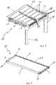
- Figure 1 shows a movable roof 100 formed by two lanes of five sheets, 1.1, 1.2, 1.3 that rest on the grooves 111 of three guide sections 110, each sheet 1.1 located between two sections 110.
- the movable roof has an upper section 101, usually resting on a wall and a lower portal frame 102 formed by a horizontal section and two vertical sections where the horizontal section rests.
- the guide sections 110 are arranged between the upper section 101 and the horizontal section of the portal frame 102.
- the upper sheet 1.2 of each lane, the closest to the upper section 101 of the movable roof 100, when all the sheets are extended is a fixed sheet 1.2 without movement; the sheet farthest from the upper section 102 when all the sheets are extended is a drive sheet 1.3, which can move from an extended position next to the horizontal section of the portal frame to a position under the fixed sheet 1.2; and the sheets 1.1 between the two previous sheets 1.2, 1.3 are intermediate sheets 1.1 that move only when the drive sheet 1.3 which pulls said intermediate sheets 1.1 moves.
- the sections of the movable roof are preferably made of aluminum.
- the sun roof 100 can have two sheets, a fixed sheet 1.2 and a drive sheet 1.3 or a fixed sheet 1.2, a drive sheet 1.3 and one or more intermediate sheets 1.1.
- the movable roof 100 can be manual or motorized, and in the latter, the drive sheet 1.3 is the one that preferably moves by means of a toothed belt 112 pulled by a motor that is preferably in the upper section 101.
- Figure 2 shows an example of a sheet 1.1 of a movable roof, in this case, an intermediate sheet 1.1 of a motorized movable roof 100, which is formed by four corner brackets 10, object of the present invention, that join four sections 2, 3 together, such that each corner bracket 10 joins a longitudinal section 2 to a transverse section 3.
- the transverse sections 3 are parallel to each other, the longitudinal sections 2 are parallel to each other, and each transverse section 3 forms a 90° angle with a longitudinal section 2 when it joins the corner bracket 10.
- the longitudinal sections can be equal to or different from each other, like the transverse sections, although the longitudinal sections will be preferably different from each other, while the transverse sections will preferably be equal.
- the transverse sections 3 are those that are inserted into the grooves 111 of the guide sections 110 of the movable roof 100, being parallel to said guide sections 110, And they are usually shorter than the longitudinal sections 2.
- the sections of the sheet 2, 3 are preferably made of aluminum like the corner brackets 10.
- Figure 3 shows a detailed cross section of the sun roof 100, which shows the previously described elements and how the sheets are located on the guide sections 110, the corner brackets 10 resting on the grooves 111 of said guide sections 110.
- FIG. 4 shows an upper perspective view of a universal corner bracket 10 according to the present invention
- Figure 5 shows a lower perspective view of the corner bracket 10.
- Said corner bracket 10 preferably comprises a supporting body 13 with a first side 131 and a second side 132 forming a 90° angle, each side having an upper face that makes up the upper face of the supporting body 13, a lower face 135 that makes up the lower face of the supporting body 13, a rear face and a front face, a first front face 134 of the first side 131 and a second front face 133 of the second side 134 of the supporting body 13, and having two attachments, a first attachment 12 after the first side 131 and a second attachment 11 after the second side 132, which are inserted into the sections 2, 3 that make up the sheet, and therefore have a shape that is complementary to the inside of said sections 2, 3.
- Said hole 16 passes through a wall in the lower face 135 of the supporting body 13 to access the housing 16.2, and after said housing, there is another hole 16.1 in the supporting body 13.
- Said second hole 15 is preferably a through hole and reaches the lower face 135, 174 of the supporting body 13 where there is another hole 15.1.
- said second hole 15 is in a third projection or attachment 17 that perpendicular to the front face 134 of the first side 131 of the supporting body 13. Said attachment 17 is between the front hole 16 and the first attachment 12.
- the second vertical hole 15 is in the upper face 171 of the attachment 17 and the lower hole 15.1 corresponding to said vertical hole 15 is in the lower face 173 of said attachment 17.
- the attachments 11, 12 of the corner bracket 10 that are inserted into the sections 2, 3 that make up the sheet can be joined to said sections 2, 3 by means of different fastening means, such as, for example, adhesive or other mechanical fastening means, such as, for example and preferably, screws.
- the corner bracket 10 has through channels 18, 19 that pass through the supporting body 13 of the corner bracket 10 to be subsequently inserted into housings for said purpose made in the section 2, 3 of the sheet.
- the third attachment 17 comprises a first through channel 18, which passes through said attachment 17 and joins the lateral faces 172, 173 thereof for the insertion of said fastening means.
- the fastening means joins the corner bracket 10 to the transverse section 3.
- the supporting body 13 comprises a second through channel 19 in the lower face 135 of the supporting body 13 for the insertion of other fastening means, preferably a screw 5, that will join the corner bracket 10 to the longitudinal section 2 of the sheet.
- Said second through channel 19 Is more specifically located in the rear part of the second front face 133 of the second side 132 and in the lower face 135 of the supporting body 13.
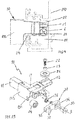
- Figure 6 shows an exploded view of a first example of a universal corner bracket 10 that incorporates wheels 21, 24 to make it easier for the sheet to roll along the grooves 111 of the guide sections 110. Specifically, it has a first wheel 21 fixed on the vertical hole 15 by means of first retention means 22 and which rotates with respect to the second vertical axis (a) of said vertical hole 15, and a second wheel 24 arranged in the housing 16.2 and fixed by means of second retention means 25 and which rotates with respect to the first axis (b) of the front hole 16.
- the retention means are preferably screws 22, 25 that are inserted into said holes and can interact with other elements to ensure the positioning thereof or ensure the correct functioning thereof, such as a washer 26 that is placed between the head of the screw 25 and the supporting body 13 to ensure correct fastening of the screw 25 between the aluminum of the supporting body 13 of the corner bracket 10 and the steel screw 25, or a bushing 23 that ensures that the wheel 21 rotates.
- These wheels 21, 24 roll on the grooves 111 of the guide sections 110, the first wheel 21 on the vertical wall of the groove 111 and the second wheel 24 on the lower or horizontal wall of the groove 111. It must be understood that the horizontal wall of the groove 111 is tilted in the installation position thereof.
- Figure 7 shows a corner bracket with the wheels 21, 24 already installed in the holes 15, 16 thereof and retained in the supporting body 13 by means of the screws 22, 25.
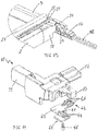
- Figure 8 shows an exploded perspective view of a universal corner bracket 10 with the installed wheels 21, 24 prior to being assembled in the sections 2, 3 of the sheet with the panel 4. The fastening screws 5, 6 of the corner bracket 10 to the sections 2, 3 are shown.
- the upper face of the first side 131 of the supporting body 13 of the corner bracket 10 can have a circular notch 137 in the place where the first wheel 21 is located that allows for the placement and rotation of said wheel 21.
- corner bracket 10 which incorporates the wheels 21, 24 is applied to the motorized movable roofs, where the intermediate sheets 1.1 will have four corner brackets 10 of this type which allows them to slide "uncontrollably” or “in a crazy manner" when the drive sheet 1.3 moves.
- corner brackets 10 of the drive sheet 1.3 that are farthest from the upper section 101 will also include these wheels 21, 24 to facilitate the sliding thereof along the grooves 111.
- Figure 9 shows a cross section of a guide section 10 that comprises a corner bracket 10 with the sliding wheels 21, 24 in one of the grooves 111 thereof, such that the first wheel 21 rests on the vertical wall of the groove and the second wheel 24 rests on the lower surface or horizontal surface thereof.
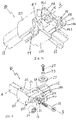
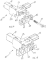
- Figure 10 shows an exploded view of a second type of corner bracket 10 according to the present invention.
- a corner bracket 10 that, in addition to the previously described wheels 21, 24, comprises a pull part 31.
- This pull part 31 is in the corner brackets 10 of the drive sheets 1.3 in motorized movable roofs and specifically in the two corner brackets 10 closest to the upper section 101 of the movable roof 100, while the two farthest corner brackets 10 will only have the wheels 21, 24 as mentioned above.
- Said pull part 31 is formed by an elongated body with a first hole 34 in one end and protrusions 32 similar to teeth on the other end to couple to another part 38 that is placed between the pull part 31 and the toothed belt 112.
- the pull part 31 is between the front face 134 of the first side 131 and second fastening means 33 that pass through the first hole 34 of the pull part 31. These second fastening means 33 are also used to fasten the second wheel 24 to the supporting body 13 of the corner bracket 10. As shown in Figure 11 , the pull part 31 is parallel to the front face 134 of the first side 131 of the supporting body 13, protruding from the corner bracket 10 through the second side 132 of the supporting body 13.
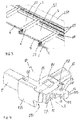
- Figure 12 shows a drive corner bracket 1.3 located with respect to a toothed belt 112 of a movable roof 100, wherein the pull part 31 coupled to the belt 112 through the intermediate grip part 38 is shown.
- Figure 13 shows a detailed view of said coupling, in which the pull part 31 is fixed to a grip part 38 of the toothed belt 112 through a hole 35 in the pull part 31 in order to insert a fastening means 39, preferably a screw, that adjusts to the grip part 38.
- a fastening means 39 preferably a screw
- Figure 14 shows another construction of a corner bracket 10 according to the present invention, in which a brake part 43 is added to the previously described universal corner bracket 10 ( Figures 4 and 5 ), the objective of which is to provide the intermediate sheets 1.1 and drive sheets 1.3 of manual movable roofs with a controlled movement, such that the sheet can move and slide along the guide sections 110 in a controlled manner since they brake by friction when the brake part 43 rests on the grooves 111 of the guide sections 110.
- These brake parts 43 are in the four corner brackets 10 of the intermediate sheets 1.1 and drive sheets 1.2 of the manual movable roofs. Furthermore, these brake parts are in the two corner brackets 10 closest to the upper section 101 of the movable roof 100 of the fixed sheets 1.2.
- Said brake part 43 has an essentially flat body with an approximate L shape and with first ribs 44 in the first end 41 and second ribs 45 in the second end 42, and it is fastened to the lower face 135 of the supporting body 13 by means of third retention means 46 that pass through a hole 47 in the part 43.
- the ribs 44, 45 arranged in the ends of the ends 41, 42 of the part 43 aim to reinforce the brake part 43 and in turn facilitate the positioning of said part 43 in the corner bracket 10 as well as act as a stop between the corner bracket 10 and the guide section 110.
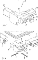
- Figure 15 shows the part 43 assembled on the corner bracket 10, such that the ribs 44 of the first end 41 face the first hole 16 of the corner bracket 10, while the ribs 45 of the second end 42 are in the side of the corner bracket 10 to which the transverse section 3 is coupled.
- Figure 16 shows a cross section of a guide section 110 where the first end 41 of the brake part 43 close to the vertical wall of the groove 111 and the second end 42 of said brake part 43 resting on the horizontal wall of the groove 111 of the guide section 110 are shown.
- Figure 17 shows another element that can join to the universal corner bracket described.
- This element is a retention part 50 which aims to retain the corner bracket 10 and the corresponding sheet to the guide section 110 or to the groove 111 therein in order to prevent the movement thereof, therefore leading to a fixed sheet 1.2 that are those closest to the upper section 101 of the movable roof 100, either manual or motorized.
- these retention parts 50 are in the two corner brackets 10 of the fixed sheet 1.2 that are farthest from the upper section 101 of the movable roof 100.
- said retention part 50 is formed by a rectangular prismatic body with an arched lower slit 51 in one end and at least one arched upper slit 52 in the opposite end, preferably two arched grooves 52.
- the retention part is between the front face 134 of the first side 131 of the supporting body 13 of the corner bracket 10 and the second retention means 25, preferably a screw, that pass through the lower slit 51 and are inserted into the first hole 16 of the front face 134 of the supporting body 13.
- the upper arched grooves 52 are used so that retention means 55, preferably screws, pass through them to fasten or retain the retention part 50 in the groove 111 of the guide section 110, specifically in the vertical wall of the groove 111.
- Figure 18 shows the retention part 50 already assembled in the corner bracket and it shows how it protrudes through the second side 132 of the corner bracket 10. This can also be seen in Figure 19 which shows a corner bracket 10 fastened to the vertical wall of the groove 111 of the guide section 110 through the retention part 50.
- the different elements 21, 24, 31, 43, 50 and additional components, which can be assembled on the universal corner bracket 10 depend on the function that this corner bracket 10 as well as the sheet 1.1, 1.2, 1.3 of which said corner bracket 10 is formed is to carry out.
Landscapes
- Engineering & Computer Science (AREA)
- Architecture (AREA)
- Civil Engineering (AREA)
- Structural Engineering (AREA)
- Physics & Mathematics (AREA)
- Electromagnetism (AREA)
- Roof Covering Using Slabs Or Stiff Sheets (AREA)
- Tents Or Canopies (AREA)
- Joining Of Corner Units Of Frames Or Wings (AREA)
Priority Applications (2)
| Application Number | Priority Date | Filing Date | Title |
|---|---|---|---|
| ES18382111T ES2866414T3 (es) | 2018-02-26 | 2018-02-26 | Esquinero universal de hojas de techos móviles |
| EP18382111.5A EP3530833B1 (fr) | 2018-02-26 | 2018-02-26 | Support d'angle universel pour panneaux de toits mobiles |
Applications Claiming Priority (1)
| Application Number | Priority Date | Filing Date | Title |
|---|---|---|---|
| EP18382111.5A EP3530833B1 (fr) | 2018-02-26 | 2018-02-26 | Support d'angle universel pour panneaux de toits mobiles |
Publications (2)
| Publication Number | Publication Date |
|---|---|
| EP3530833A1 true EP3530833A1 (fr) | 2019-08-28 |
| EP3530833B1 EP3530833B1 (fr) | 2020-12-30 |
Family
ID=61569199
Family Applications (1)
| Application Number | Title | Priority Date | Filing Date |
|---|---|---|---|
| EP18382111.5A Not-in-force EP3530833B1 (fr) | 2018-02-26 | 2018-02-26 | Support d'angle universel pour panneaux de toits mobiles |
Country Status (2)
| Country | Link |
|---|---|
| EP (1) | EP3530833B1 (fr) |
| ES (1) | ES2866414T3 (fr) |
Citations (4)
| Publication number | Priority date | Publication date | Assignee | Title |
|---|---|---|---|---|
| US3299575A (en) * | 1965-09-07 | 1967-01-24 | Universal Molding Co | Combined corner and roller for screen frames |
| US6813862B2 (en) * | 2002-01-03 | 2004-11-09 | Patio Enclosures, Inc. | Corner bracket assembly |
| US20070297854A1 (en) * | 2006-06-20 | 2007-12-27 | Ohrstrom Rolf J | Corner bracket |
| US8851787B2 (en) * | 2011-08-23 | 2014-10-07 | Andersen Corporation | Corner joint and method of manufacturing |
-
2018
- 2018-02-26 ES ES18382111T patent/ES2866414T3/es active Active
- 2018-02-26 EP EP18382111.5A patent/EP3530833B1/fr not_active Not-in-force
Patent Citations (4)
| Publication number | Priority date | Publication date | Assignee | Title |
|---|---|---|---|---|
| US3299575A (en) * | 1965-09-07 | 1967-01-24 | Universal Molding Co | Combined corner and roller for screen frames |
| US6813862B2 (en) * | 2002-01-03 | 2004-11-09 | Patio Enclosures, Inc. | Corner bracket assembly |
| US20070297854A1 (en) * | 2006-06-20 | 2007-12-27 | Ohrstrom Rolf J | Corner bracket |
| US8851787B2 (en) * | 2011-08-23 | 2014-10-07 | Andersen Corporation | Corner joint and method of manufacturing |
Also Published As
| Publication number | Publication date |
|---|---|
| EP3530833B1 (fr) | 2020-12-30 |
| ES2866414T3 (es) | 2021-10-19 |
Similar Documents
| Publication | Publication Date | Title |
|---|---|---|
| US4456049A (en) | Spring biased tilt rod control system | |
| PT1867824E (pt) | Um método para montar um elemento auxiliar no caixilho de uma porta ou janela | |
| US9915075B2 (en) | Adjustment device, system and methods | |
| WO2015093285A1 (fr) | Leve-vitre et procede pour la fabrication de leve-vitre | |
| EP3530833B1 (fr) | Support d'angle universel pour panneaux de toits mobiles | |
| EP2799653B1 (fr) | Ensemble d'entraînement motorisé pour une porte coulissante automatique | |
| AU2006205960A1 (en) | An adjustment element | |
| KR200425100Y1 (ko) | 창틀 고정용 브래키트 | |
| CN1892930B (zh) | 电机驱动式滑动型可变电阻器 | |
| JP5427098B2 (ja) | レール装置 | |
| JP2762182B2 (ja) | 建物の外壁用ガラス板等の取付け構造 | |
| US4846248A (en) | Strap winder, in particular for skylight roller blinds | |
| JP6543749B1 (ja) | 吊り下げ式ドアのドアガイド機構 | |
| KR101031097B1 (ko) | 장력조절기구를 구비한 자동문 | |
| GB2343475A (en) | An adjustable frame comprising a latching arrangement | |
| WO2020218604A1 (fr) | Dispositif de déplacement d'objet cible | |
| KR200428811Y1 (ko) | 창틀 고정용 브래키트 | |
| JP5622425B2 (ja) | レール装置 | |
| CN218522522U (zh) | 一种门窗用辅助安装装置 | |
| JP3904382B2 (ja) | アーム式ウインドレギュレータ及びその組立方法 | |
| JP2014037672A (ja) | ウインドレギュレータ | |
| NZ530730A (en) | Latch assembly | |
| JPH085853Y2 (ja) | サンルーフ装置のガイドパイプ取付構造 | |
| DE602005004212D1 (de) | Schiebeelement für Fensterheberantrieb in Kraftfahrzeugen | |
| KR19990083683A (ko) | 이중마루의다공판넬용댐퍼조절장치 |
Legal Events
| Date | Code | Title | Description |
|---|---|---|---|
| PUAI | Public reference made under article 153(3) epc to a published international application that has entered the european phase |
Free format text: ORIGINAL CODE: 0009012 |
|
| STAA | Information on the status of an ep patent application or granted ep patent |
Free format text: STATUS: THE APPLICATION HAS BEEN PUBLISHED |
|
| AK | Designated contracting states |
Kind code of ref document: A1 Designated state(s): AL AT BE BG CH CY CZ DE DK EE ES FI FR GB GR HR HU IE IS IT LI LT LU LV MC MK MT NL NO PL PT RO RS SE SI SK SM TR |
|
| AX | Request for extension of the european patent |
Extension state: BA ME |
|
| STAA | Information on the status of an ep patent application or granted ep patent |
Free format text: STATUS: REQUEST FOR EXAMINATION WAS MADE |
|
| 17P | Request for examination filed |
Effective date: 20200227 |
|
| RAV | Requested validation state of the european patent: fee paid |
Extension state: MA Effective date: 20200227 |
|
| RBV | Designated contracting states (corrected) |
Designated state(s): AL AT BE BG CH CY CZ DE DK EE ES FI FR GB GR HR HU IE IS IT LI LT LU LV MC MK MT NL NO PL PT RO RS SE SI SK SM TR |
|
| GRAP | Despatch of communication of intention to grant a patent |
Free format text: ORIGINAL CODE: EPIDOSNIGR1 |
|
| STAA | Information on the status of an ep patent application or granted ep patent |
Free format text: STATUS: GRANT OF PATENT IS INTENDED |
|
| INTG | Intention to grant announced |
Effective date: 20200717 |
|
| GRAS | Grant fee paid |
Free format text: ORIGINAL CODE: EPIDOSNIGR3 |
|
| GRAA | (expected) grant |
Free format text: ORIGINAL CODE: 0009210 |
|
| STAA | Information on the status of an ep patent application or granted ep patent |
Free format text: STATUS: THE PATENT HAS BEEN GRANTED |
|
| AK | Designated contracting states |
Kind code of ref document: B1 Designated state(s): AL AT BE BG CH CY CZ DE DK EE ES FI FR GB GR HR HU IE IS IT LI LT LU LV MC MK MT NL NO PL PT RO RS SE SI SK SM TR |
|
| REG | Reference to a national code |
Ref country code: GB Ref legal event code: FG4D |
|
| REG | Reference to a national code |
Ref country code: DE Ref legal event code: R096 Ref document number: 602018011337 Country of ref document: DE |
|
| REG | Reference to a national code |
Ref country code: AT Ref legal event code: REF Ref document number: 1350052 Country of ref document: AT Kind code of ref document: T Effective date: 20210115 |
|
| REG | Reference to a national code |
Ref country code: IE Ref legal event code: FG4D |
|
| PG25 | Lapsed in a contracting state [announced via postgrant information from national office to epo] |
Ref country code: RS Free format text: LAPSE BECAUSE OF FAILURE TO SUBMIT A TRANSLATION OF THE DESCRIPTION OR TO PAY THE FEE WITHIN THE PRESCRIBED TIME-LIMIT Effective date: 20201230 Ref country code: FI Free format text: LAPSE BECAUSE OF FAILURE TO SUBMIT A TRANSLATION OF THE DESCRIPTION OR TO PAY THE FEE WITHIN THE PRESCRIBED TIME-LIMIT Effective date: 20201230 Ref country code: NO Free format text: LAPSE BECAUSE OF FAILURE TO SUBMIT A TRANSLATION OF THE DESCRIPTION OR TO PAY THE FEE WITHIN THE PRESCRIBED TIME-LIMIT Effective date: 20210330 Ref country code: GR Free format text: LAPSE BECAUSE OF FAILURE TO SUBMIT A TRANSLATION OF THE DESCRIPTION OR TO PAY THE FEE WITHIN THE PRESCRIBED TIME-LIMIT Effective date: 20210331 |
|
| REG | Reference to a national code |
Ref country code: AT Ref legal event code: MK05 Ref document number: 1350052 Country of ref document: AT Kind code of ref document: T Effective date: 20201230 |
|
| PG25 | Lapsed in a contracting state [announced via postgrant information from national office to epo] |
Ref country code: BG Free format text: LAPSE BECAUSE OF FAILURE TO SUBMIT A TRANSLATION OF THE DESCRIPTION OR TO PAY THE FEE WITHIN THE PRESCRIBED TIME-LIMIT Effective date: 20210330 Ref country code: LV Free format text: LAPSE BECAUSE OF FAILURE TO SUBMIT A TRANSLATION OF THE DESCRIPTION OR TO PAY THE FEE WITHIN THE PRESCRIBED TIME-LIMIT Effective date: 20201230 Ref country code: SE Free format text: LAPSE BECAUSE OF FAILURE TO SUBMIT A TRANSLATION OF THE DESCRIPTION OR TO PAY THE FEE WITHIN THE PRESCRIBED TIME-LIMIT Effective date: 20201230 |
|
| REG | Reference to a national code |
Ref country code: NL Ref legal event code: MP Effective date: 20201230 |
|
| PG25 | Lapsed in a contracting state [announced via postgrant information from national office to epo] |
Ref country code: HR Free format text: LAPSE BECAUSE OF FAILURE TO SUBMIT A TRANSLATION OF THE DESCRIPTION OR TO PAY THE FEE WITHIN THE PRESCRIBED TIME-LIMIT Effective date: 20201230 |
|
| REG | Reference to a national code |
Ref country code: LT Ref legal event code: MG9D |
|
| PG25 | Lapsed in a contracting state [announced via postgrant information from national office to epo] |
Ref country code: SK Free format text: LAPSE BECAUSE OF FAILURE TO SUBMIT A TRANSLATION OF THE DESCRIPTION OR TO PAY THE FEE WITHIN THE PRESCRIBED TIME-LIMIT Effective date: 20201230 Ref country code: EE Free format text: LAPSE BECAUSE OF FAILURE TO SUBMIT A TRANSLATION OF THE DESCRIPTION OR TO PAY THE FEE WITHIN THE PRESCRIBED TIME-LIMIT Effective date: 20201230 Ref country code: CZ Free format text: LAPSE BECAUSE OF FAILURE TO SUBMIT A TRANSLATION OF THE DESCRIPTION OR TO PAY THE FEE WITHIN THE PRESCRIBED TIME-LIMIT Effective date: 20201230 Ref country code: LT Free format text: LAPSE BECAUSE OF FAILURE TO SUBMIT A TRANSLATION OF THE DESCRIPTION OR TO PAY THE FEE WITHIN THE PRESCRIBED TIME-LIMIT Effective date: 20201230 Ref country code: RO Free format text: LAPSE BECAUSE OF FAILURE TO SUBMIT A TRANSLATION OF THE DESCRIPTION OR TO PAY THE FEE WITHIN THE PRESCRIBED TIME-LIMIT Effective date: 20201230 Ref country code: PT Free format text: LAPSE BECAUSE OF FAILURE TO SUBMIT A TRANSLATION OF THE DESCRIPTION OR TO PAY THE FEE WITHIN THE PRESCRIBED TIME-LIMIT Effective date: 20210430 |
|
| PG25 | Lapsed in a contracting state [announced via postgrant information from national office to epo] |
Ref country code: AT Free format text: LAPSE BECAUSE OF FAILURE TO SUBMIT A TRANSLATION OF THE DESCRIPTION OR TO PAY THE FEE WITHIN THE PRESCRIBED TIME-LIMIT Effective date: 20201230 Ref country code: PL Free format text: LAPSE BECAUSE OF FAILURE TO SUBMIT A TRANSLATION OF THE DESCRIPTION OR TO PAY THE FEE WITHIN THE PRESCRIBED TIME-LIMIT Effective date: 20201230 |
|
| REG | Reference to a national code |
Ref country code: DE Ref legal event code: R119 Ref document number: 602018011337 Country of ref document: DE |
|
| PG25 | Lapsed in a contracting state [announced via postgrant information from national office to epo] |
Ref country code: MC Free format text: LAPSE BECAUSE OF FAILURE TO SUBMIT A TRANSLATION OF THE DESCRIPTION OR TO PAY THE FEE WITHIN THE PRESCRIBED TIME-LIMIT Effective date: 20201230 Ref country code: IS Free format text: LAPSE BECAUSE OF FAILURE TO SUBMIT A TRANSLATION OF THE DESCRIPTION OR TO PAY THE FEE WITHIN THE PRESCRIBED TIME-LIMIT Effective date: 20210430 |
|
| REG | Reference to a national code |
Ref country code: ES Ref legal event code: FG2A Ref document number: 2866414 Country of ref document: ES Kind code of ref document: T3 Effective date: 20211019 |
|
| REG | Reference to a national code |
Ref country code: BE Ref legal event code: MM Effective date: 20210228 |
|
| PG25 | Lapsed in a contracting state [announced via postgrant information from national office to epo] |
Ref country code: CH Free format text: LAPSE BECAUSE OF NON-PAYMENT OF DUE FEES Effective date: 20210228 Ref country code: AL Free format text: LAPSE BECAUSE OF FAILURE TO SUBMIT A TRANSLATION OF THE DESCRIPTION OR TO PAY THE FEE WITHIN THE PRESCRIBED TIME-LIMIT Effective date: 20201230 Ref country code: LU Free format text: LAPSE BECAUSE OF NON-PAYMENT OF DUE FEES Effective date: 20210226 Ref country code: LI Free format text: LAPSE BECAUSE OF NON-PAYMENT OF DUE FEES Effective date: 20210228 |
|
| PLBE | No opposition filed within time limit |
Free format text: ORIGINAL CODE: 0009261 |
|
| STAA | Information on the status of an ep patent application or granted ep patent |
Free format text: STATUS: NO OPPOSITION FILED WITHIN TIME LIMIT |
|
| PG25 | Lapsed in a contracting state [announced via postgrant information from national office to epo] |
Ref country code: DK Free format text: LAPSE BECAUSE OF FAILURE TO SUBMIT A TRANSLATION OF THE DESCRIPTION OR TO PAY THE FEE WITHIN THE PRESCRIBED TIME-LIMIT Effective date: 20201230 |
|
| 26N | No opposition filed |
Effective date: 20211001 |
|
| PG25 | Lapsed in a contracting state [announced via postgrant information from national office to epo] |
Ref country code: FR Free format text: LAPSE BECAUSE OF NON-PAYMENT OF DUE FEES Effective date: 20210228 Ref country code: DE Free format text: LAPSE BECAUSE OF NON-PAYMENT OF DUE FEES Effective date: 20210901 Ref country code: IE Free format text: LAPSE BECAUSE OF NON-PAYMENT OF DUE FEES Effective date: 20210226 |
|
| PG25 | Lapsed in a contracting state [announced via postgrant information from national office to epo] |
Ref country code: SI Free format text: LAPSE BECAUSE OF FAILURE TO SUBMIT A TRANSLATION OF THE DESCRIPTION OR TO PAY THE FEE WITHIN THE PRESCRIBED TIME-LIMIT Effective date: 20201230 |
|
| PG25 | Lapsed in a contracting state [announced via postgrant information from national office to epo] |
Ref country code: IS Free format text: LAPSE BECAUSE OF FAILURE TO SUBMIT A TRANSLATION OF THE DESCRIPTION OR TO PAY THE FEE WITHIN THE PRESCRIBED TIME-LIMIT Effective date: 20210430 |
|
| PG25 | Lapsed in a contracting state [announced via postgrant information from national office to epo] |
Ref country code: BE Free format text: LAPSE BECAUSE OF NON-PAYMENT OF DUE FEES Effective date: 20210228 |
|
| GBPC | Gb: european patent ceased through non-payment of renewal fee |
Effective date: 20220226 |
|
| PG25 | Lapsed in a contracting state [announced via postgrant information from national office to epo] |
Ref country code: GB Free format text: LAPSE BECAUSE OF NON-PAYMENT OF DUE FEES Effective date: 20220226 |
|
| PGFP | Annual fee paid to national office [announced via postgrant information from national office to epo] |
Ref country code: ES Payment date: 20230301 Year of fee payment: 6 |
|
| PGFP | Annual fee paid to national office [announced via postgrant information from national office to epo] |
Ref country code: IT Payment date: 20230321 Year of fee payment: 6 |
|
| PG25 | Lapsed in a contracting state [announced via postgrant information from national office to epo] |
Ref country code: NL Free format text: LAPSE BECAUSE OF NON-PAYMENT OF DUE FEES Effective date: 20201230 Ref country code: CY Free format text: LAPSE BECAUSE OF FAILURE TO SUBMIT A TRANSLATION OF THE DESCRIPTION OR TO PAY THE FEE WITHIN THE PRESCRIBED TIME-LIMIT Effective date: 20201230 |
|
| PG25 | Lapsed in a contracting state [announced via postgrant information from national office to epo] |
Ref country code: SM Free format text: LAPSE BECAUSE OF FAILURE TO SUBMIT A TRANSLATION OF THE DESCRIPTION OR TO PAY THE FEE WITHIN THE PRESCRIBED TIME-LIMIT Effective date: 20201230 Ref country code: HU Free format text: LAPSE BECAUSE OF FAILURE TO SUBMIT A TRANSLATION OF THE DESCRIPTION OR TO PAY THE FEE WITHIN THE PRESCRIBED TIME-LIMIT; INVALID AB INITIO Effective date: 20180226 |
|
| PG25 | Lapsed in a contracting state [announced via postgrant information from national office to epo] |
Ref country code: MK Free format text: LAPSE BECAUSE OF FAILURE TO SUBMIT A TRANSLATION OF THE DESCRIPTION OR TO PAY THE FEE WITHIN THE PRESCRIBED TIME-LIMIT Effective date: 20201230 |
|
| VS25 | Lapsed in a validation state [announced via postgrant information from nat. office to epo] |
Ref country code: MA Free format text: LAPSE BECAUSE OF FAILURE TO SUBMIT A TRANSLATION OF THE DESCRIPTION OR TO PAY THE FEE WITHIN THE PRESCRIBED TIME-LIMIT Effective date: 20201230 |
|
| PG25 | Lapsed in a contracting state [announced via postgrant information from national office to epo] |
Ref country code: MT Free format text: LAPSE BECAUSE OF FAILURE TO SUBMIT A TRANSLATION OF THE DESCRIPTION OR TO PAY THE FEE WITHIN THE PRESCRIBED TIME-LIMIT Effective date: 20201230 |
|
| PG25 | Lapsed in a contracting state [announced via postgrant information from national office to epo] |
Ref country code: IT Free format text: LAPSE BECAUSE OF NON-PAYMENT OF DUE FEES Effective date: 20240226 |
|
| REG | Reference to a national code |
Ref country code: ES Ref legal event code: FD2A Effective date: 20250331 |
|
| PG25 | Lapsed in a contracting state [announced via postgrant information from national office to epo] |
Ref country code: ES Free format text: LAPSE BECAUSE OF NON-PAYMENT OF DUE FEES Effective date: 20240227 |
|
| PG25 | Lapsed in a contracting state [announced via postgrant information from national office to epo] |
Ref country code: TR Free format text: LAPSE BECAUSE OF FAILURE TO SUBMIT A TRANSLATION OF THE DESCRIPTION OR TO PAY THE FEE WITHIN THE PRESCRIBED TIME-LIMIT Effective date: 20201230 |