EP3530491A1 - Luftreifen - Google Patents
Luftreifen Download PDFInfo
- Publication number
- EP3530491A1 EP3530491A1 EP18206704.1A EP18206704A EP3530491A1 EP 3530491 A1 EP3530491 A1 EP 3530491A1 EP 18206704 A EP18206704 A EP 18206704A EP 3530491 A1 EP3530491 A1 EP 3530491A1
- Authority
- EP
- European Patent Office
- Prior art keywords
- side ring
- decoupling
- pneumatic tire
- grooves
- groove
- Prior art date
- Legal status (The legal status is an assumption and is not a legal conclusion. Google has not performed a legal analysis and makes no representation as to the accuracy of the status listed.)
- Pending
Links
Images


Classifications
-
- B—PERFORMING OPERATIONS; TRANSPORTING
- B60—VEHICLES IN GENERAL
- B60C—VEHICLE TYRES; TYRE INFLATION; TYRE CHANGING; CONNECTING VALVES TO INFLATABLE ELASTIC BODIES IN GENERAL; DEVICES OR ARRANGEMENTS RELATED TO TYRES
- B60C11/00—Tyre tread bands; Tread patterns; Anti-skid inserts
- B60C11/01—Shape of the shoulders between tread and sidewall, e.g. rounded, stepped or cantilevered
-
- B—PERFORMING OPERATIONS; TRANSPORTING
- B60—VEHICLES IN GENERAL
- B60C—VEHICLE TYRES; TYRE INFLATION; TYRE CHANGING; CONNECTING VALVES TO INFLATABLE ELASTIC BODIES IN GENERAL; DEVICES OR ARRANGEMENTS RELATED TO TYRES
- B60C13/00—Tyre sidewalls; Protecting, decorating, marking, or the like, thereof
- B60C13/02—Arrangement of grooves or ribs
-
- B—PERFORMING OPERATIONS; TRANSPORTING
- B60—VEHICLES IN GENERAL
- B60C—VEHICLE TYRES; TYRE INFLATION; TYRE CHANGING; CONNECTING VALVES TO INFLATABLE ELASTIC BODIES IN GENERAL; DEVICES OR ARRANGEMENTS RELATED TO TYRES
- B60C23/00—Devices for measuring, signalling, controlling, or distributing tyre pressure or temperature, specially adapted for mounting on vehicles; Arrangement of tyre inflating devices on vehicles, e.g. of pumps or of tanks; Tyre cooling arrangements
- B60C23/18—Tyre cooling arrangements, e.g. heat shields
- B60C23/19—Tyre cooling arrangements, e.g. heat shields for dissipating heat
-
- B—PERFORMING OPERATIONS; TRANSPORTING
- B60—VEHICLES IN GENERAL
- B60C—VEHICLE TYRES; TYRE INFLATION; TYRE CHANGING; CONNECTING VALVES TO INFLATABLE ELASTIC BODIES IN GENERAL; DEVICES OR ARRANGEMENTS RELATED TO TYRES
- B60C11/00—Tyre tread bands; Tread patterns; Anti-skid inserts
- B60C11/01—Shape of the shoulders between tread and sidewall, e.g. rounded, stepped or cantilevered
- B60C2011/013—Shape of the shoulders between tread and sidewall, e.g. rounded, stepped or cantilevered provided with a recessed portion
-
- B—PERFORMING OPERATIONS; TRANSPORTING
- B60—VEHICLES IN GENERAL
- B60C—VEHICLE TYRES; TYRE INFLATION; TYRE CHANGING; CONNECTING VALVES TO INFLATABLE ELASTIC BODIES IN GENERAL; DEVICES OR ARRANGEMENTS RELATED TO TYRES
- B60C11/00—Tyre tread bands; Tread patterns; Anti-skid inserts
- B60C11/03—Tread patterns
- B60C2011/0337—Tread patterns characterised by particular design features of the pattern
- B60C2011/0339—Grooves
- B60C2011/0358—Lateral grooves, i.e. having an angle of 45 to 90 degees to the equatorial plane
-
- B—PERFORMING OPERATIONS; TRANSPORTING
- B60—VEHICLES IN GENERAL
- B60C—VEHICLE TYRES; TYRE INFLATION; TYRE CHANGING; CONNECTING VALVES TO INFLATABLE ELASTIC BODIES IN GENERAL; DEVICES OR ARRANGEMENTS RELATED TO TYRES
- B60C2200/00—Tyres specially adapted for particular applications
- B60C2200/04—Tyres specially adapted for particular applications for road vehicles, e.g. passenger cars
-
- B—PERFORMING OPERATIONS; TRANSPORTING
- B60—VEHICLES IN GENERAL
- B60C—VEHICLE TYRES; TYRE INFLATION; TYRE CHANGING; CONNECTING VALVES TO INFLATABLE ELASTIC BODIES IN GENERAL; DEVICES OR ARRANGEMENTS RELATED TO TYRES
- B60C2200/00—Tyres specially adapted for particular applications
- B60C2200/06—Tyres specially adapted for particular applications for heavy duty vehicles
Definitions
- the present invention relates to a pneumatic tire, and more particularly, to a pneumatic tire having an improved decoupling groove in a shoulder.
- Heavy-duty tires require durability and wear performance represented as mileage. This mileage performance is again classified into two parts: the first is absolute wear performance and the second is abnormal wear resistance performance. There are many techniques for improving the abnormal wear resistance performance, but a typical technique of them is to install a decoupling groove, which is an abnormal wear prevention mechanism, at a shoulder end, as illustrated in FIG. 1 .
- the decoupling groove is widely employed for tires running at high speed/for long distance.
- the principle of the decoupling groove is to form a sacrificial rib separated by the decoupling groove at the shoulder end, to concentrate the frictional energy generated in the outermost rib on the intentionally separated sacrificial rib to accelerate the wear of the sacrificial rib and suppress the wear of the outermost rib, and to prevent irregular wear from spreading to the main rib when the irregular wear occurs on the sacrificial rib.
- Korean Patent No. 10-1053904 entitled “Heavy-duty Vehicle Tire with Decoupling Groove", relates to a heavy-duty vehicle tire, and more particularly, to a tire in which a decoupling groove is installed in a shoulder portion.
- Korean Patent No. 10-1053904 discloses a tire in which a decoupling groove is installed at a tread corner and the angle (a) formed by the depth direction of the decoupling groove 5 and the tread ground plane is 97 to 100 degrees.
- This technology allows a sacrificial rib to be formed outside the decoupling groove to protect an inner tread edge rib while allowing a sufficiently deep decoupling groove to be installed between the sacrificial rib and the tread edge rib to fully block the abnormal wear of the sacrificial rib from transferring to the tread edge rib, allows the sufficiently deep decoupling groove to block the vibration transmission of a sidewall, and allows the decoupling groove to be installed close to a belt edge to increase an effect of dissipating heat from the belt edge.
- US 2009/0065115 A1 is a patent related to the Continental's decoupling groove.
- the Continental patent has a circumferential decoupling rib.
- US 2009/0065115 A1 has an effect of suppressing irregular wear by a shoulder-side rib bearing more weight.
- US 8074690 B2 ( US 2010/0116390 A1 ) is a technology applied by the Goodyear Tire & Rubber Company and aims to prevent cracks from growing from a side wall to a tread.
- US 8074690 B2 discloses a rib having a rounded edge to reduce irregular wear and adopts a decoupling groove.
- US 8074690 B2 also discloses a shoulder-side rib providing a protection function.
- EP 0 996 551 B1 is a patent related to the Michelin's decoupling groove.
- the decoupling groove of EP 0 996 551 B1 differs from those of the related arts in shape and length, and increases wear reduction and lateral safety by the shoulder rib of this shape.
- an aspect of the present invention provides a pneumatic tire including a tread (100), a sidewall (200), and a bead (300).
- the pneumatic tire includes one or more side ring decoupling grooves (400) formed along the circumference of the tire at an upper portion of the sidewall (200), and the side ring decoupling grooves (400) are formed in a direction parallel with the ground.
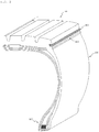
- FIG. 2 is a perspective view illustrating a main portion of a pneumatic tire according to an embodiment of the present invention.
- FIG. 3 is a cross-sectional view illustrating the main portion of the pneumatic tire according to the embodiment of the present invention.
- the present invention provides a pneumatic tire including a tread 100, a sidewall 200, and a bead 300.
- the pneumatic tire includes one or more side ring decoupling grooves 400 formed along the circumference of the tire at the upper portion of the sidewall 200, and the side ring decoupling grooves 400 are formed in a direction parallel with the ground coming into contact with the tire.
- the side ring decoupling grooves 400 expand the surface area of the upper portion of the sidewall 200 to improve the heat dissipation performance of the end of the tread 100, namely of a tread shoulder, thereby enhancing the durability of the tire. In addition, it is possible to expect an effect of improving the wear resistance performance of the tread 100 by relieving the contact pressure applied to the shoulder. That is, the side ring decoupling grooves 400 of the present invention perform the function of the sacrificial rib of the conventional decoupling groove and improve heat dissipation performance through an increase in surface area.
- the ground comes into contact with the tire in a horizontal direction x while the tire is running, and the depth direction of each of the side ring decoupling grooves 400 is parallel with the horizontal direction x.
- the depth direction of the side ring decoupling groove 400 forms an angle of ⁇ 15° with the horizontal direction x according to the shape and structure of the tire.
- Only one side ring decoupling groove 400 may be installed, but three side ring decoupling grooves 400 are preferably installed as illustrated in FIGS. 2 and 3 . If the number of side ring decoupling grooves is less than three, the surface area is not sufficient, which may lead to a poor heat dissipation effect. On the other hand, if it is more than three, the stiffness of the corresponding part may be excessively weakened.
- the limitation of the number of side ring decoupling grooves is significant in view of the fact that one of the main purposes of the decoupling groove is to dissipate heat from the shoulder to prevent a decrease in durability due to thermal fatigue.
- the distance w3 between the side ring decoupling grooves 400 is preferably equal to or greater than the width w2 of each of the side ring decoupling grooves 400. If the distance w3 between the side ring decoupling grooves 400 is smaller than the width w2 of the side ring decoupling groove 400, the stiffness of the corresponding part may be excessively weakened to cause cracks. On the other hand, if the same number of side ring decoupling grooves 400 is installed, the thermal conductivity of the corresponding part is lowered as the distance w3 between the side ring decoupling grooves 400 beomces small, which may lead to a decrease in heat dissipation efficiency. For this reason, it is configured that the distance w3 between the side ring decoupling grooves 400 is equal to or greater than the width w2 of the side ring decoupling groove 400.
- each of the side ring decoupling grooves 400 has a depth w1 of 1 to 10 mm and a width w2 of 1 to 5 mm.
- the stiffness of the upper end of the sidewall may be decreased and cracks may be caused.
- the depth w1 of the side ring decoupling groove 400 is too small, it is impossible to expect a sufficient heat dissipation effect since a sufficient surface area is not obtained and to expect a sufficient buffering effect on the upper portion of the sidewall. For this reason, the above numerical limitation is significant.
- the present invention provides a configuration in which a mold distribution protrusion 500 is formed beneath the side ring decoupling grooves 400.
- the mold distribution protrusion 500 is formed at a portion where a tread mold for forming the tread 100 touches a sidewall mold for forming the sidewall 200 at the time of forming the tire.
- the side ring decoupling grooves 400 of the present invention are to enhance the durability of the upper portion of the sidewall 200, i.e., the durability of the shoulder, and are installed at the upper portion of the sidewall 200. However, this installation position is adjacent to a position where the tread mold and sidewall mold as vulcanized molds touch each other. Thus, tension may be applied to the side ring decoupling grooves 400 in the process of separating the molds from each other after the tire is formed, which may lead to breakage such as tearing the side ring decoupling grooves 400.
- the present invention provides a configuration in which the mold distribution protrusion 500 is formed at a position where the tread mold and sidewall mold as vulcanized molds touch each other to minimize the tension applied to the side ring decoupling grooves 400 in the process of separating the molds from each other.
- the mold distribution protrusion 500 preferably has a triangular shape having a vertex in cross section, and more preferably forms a curved surface at both sides leading from the vertex.
- the distance w4 between the center of the mold distribution protrusion 500 and the associated side ring decoupling groove 400 is preferably 4 to 10 mm.
- the distance w4 between the center of the mold distribution protrusion 500 and the side ring decoupling groove 400 is too small, a step is formed to apply rather a larger tension to the side ring decoupling groove 400, which causes cracks.
- the distance w4 between the center of the mold distribution protrusion 500 and the side ring decoupling groove 400 is too great, a tension cancellation effect may be less than expected. For this reason, the numerical limitation of the distance w4 between the center of the mold distribution protrusion 500 and the side ring decoupling groove 400 is significant.
- FIG. 4 is a cross-sectional view illustrating a main portion in an implementation example to which a shoulder decoupling groove is additionally applied.
- a shoulder decoupling groove 600 is formed above the side ring decoupling grooves 400, and includes an inlet 610 formed at the outer side thereof and an inner groove 620 formed at the inner side thereof. This configuration provides additional heat dissipation performance of the shoulder, and enables a sacrificial rib 630 formed by the shoulder decoupling groove 600 to further distribute concentration of stress while the tire is running.
- the side ring decoupling grooves 400 distribute the force applied to the sacrificial rib 630.
- the distance w5 between the shoulder decoupling groove 600 and the associated side ring decoupling groove 400 is preferably 0 to 20 mm.
- the side ring decoupling groove 400 does not sufficiently perform the buffering action of the sacrificial rib 630.
- the distance w5 between the shoulder decoupling groove 600 and the side ring decoupling groove 400 is less than "0" and the side ring decoupling groove 400 approaches the sacrificial rib 630, the stiffness of the sacrificial rib 630 may be excessively lowered. For this reason, the numerical limitation of the distance w5 between the shoulder decoupling groove 600 and the side ring decoupling groove 400 is significant.
- the distance w6 between the outermost end of each of the side ring decoupling grooves 400 and the inner groove 620 is greater than the depth w1 of the side ring decoupling groove 400. This is to prevent the stiffness of the sacrificial rib 630 from being excessively lowered.
- the side ring decoupling groove enlarges the surface area of the upper portion of the sidewall, it is possible to improve the heat dissipation performance of the end of the tread, namely of the tread shoulder, and enhance the durability of the tire. In addition, it is possible to expect an effect of improving the wear resistance performance of the tread by relieving the contact pressure applied to the shoulder.
Landscapes
- Engineering & Computer Science (AREA)
- Mechanical Engineering (AREA)
- Tires In General (AREA)
Applications Claiming Priority (1)
| Application Number | Priority Date | Filing Date | Title |
|---|---|---|---|
| KR1020180023172A KR102051856B1 (ko) | 2018-02-26 | 2018-02-26 | 공기입타이어 |
Publications (1)
| Publication Number | Publication Date |
|---|---|
| EP3530491A1 true EP3530491A1 (de) | 2019-08-28 |
Family
ID=64331900
Family Applications (1)
| Application Number | Title | Priority Date | Filing Date |
|---|---|---|---|
| EP18206704.1A Pending EP3530491A1 (de) | 2018-02-26 | 2018-11-16 | Luftreifen |
Country Status (5)
| Country | Link |
|---|---|
| US (1) | US20190263185A1 (de) |
| EP (1) | EP3530491A1 (de) |
| JP (1) | JP6782753B2 (de) |
| KR (1) | KR102051856B1 (de) |
| CN (1) | CN110194031A (de) |
Families Citing this family (3)
| Publication number | Priority date | Publication date | Assignee | Title |
|---|---|---|---|---|
| KR102371143B1 (ko) * | 2020-08-12 | 2022-03-07 | 금호타이어 주식회사 | 공기입 타이어 |
| US20220396102A1 (en) * | 2021-06-15 | 2022-12-15 | Cooper Tire & Rubber Company | Decoupling groove for tire |
| KR102576910B1 (ko) | 2021-07-19 | 2023-09-12 | 금호타이어 주식회사 | 보강된 디커플링 그루브가 적용된 중하중용 공기입 타이어 |
Citations (8)
| Publication number | Priority date | Publication date | Assignee | Title |
|---|---|---|---|---|
| EP1184206A1 (de) * | 2000-08-31 | 2002-03-06 | The Goodyear Tire & Rubber Company | LKW-Reifen |
| EP0996551B1 (de) | 1998-01-26 | 2003-04-23 | Michelin Recherche Et Technique S.A. | Reifen mit verbessertem laufflächenteil zur vermindung der fehlerbildung am laufflächenteil die die unzufriedenheit des kunden hervorruft |
| EP1314581A1 (de) * | 2001-11-27 | 2003-05-28 | Sumitomo Rubber Industries, Ltd. | Fahrzeugluftreifen mit Umfangsrillen in der äusseren Seitenwand |
| EP1400375A2 (de) * | 2002-09-19 | 2004-03-24 | The Goodyear Tire & Rubber Company | LKW Lenkreifen, Reifenformwerkzeug und Verfahren zum Formen |
| US20040060628A1 (en) * | 2002-09-30 | 2004-04-01 | Grimm John H.W. | Heavy duty pneumatic tire |
| US20090065115A1 (en) | 2007-09-11 | 2009-03-12 | Continental Tire North America, Inc. | Pneumatic tire with decoupling groove |
| US20100116390A1 (en) | 2008-11-11 | 2010-05-13 | Jeffrey Leon Sevart | Decoupling groove for pneumatic tire tread |
| KR101053904B1 (ko) | 2008-12-15 | 2011-08-04 | 한국타이어 주식회사 | 디커플링 그루브를 가지는 중하중 차량용 타이어 |
Family Cites Families (7)
| Publication number | Priority date | Publication date | Assignee | Title |
|---|---|---|---|---|
| JP2829859B2 (ja) * | 1988-08-10 | 1998-12-02 | 横浜ゴム株式会社 | 空気入りラジアルタイヤ |
| BRPI0400172A (pt) * | 2003-02-11 | 2004-12-28 | Goodyear Tire & Rubber | Pneumáticos papa eixos de direção de caminhão, um molde e um método de moldagem |
| KR100711621B1 (ko) * | 2005-09-05 | 2007-04-30 | 금호타이어 주식회사 | 중하중용 공기입 래디알 타이어 |
| JP5101114B2 (ja) * | 2007-01-19 | 2012-12-19 | 東洋ゴム工業株式会社 | 空気入りタイヤ |
| JP4996288B2 (ja) * | 2007-03-07 | 2012-08-08 | 株式会社ブリヂストン | 空気入りタイヤ、及び、それを製造する加硫成形装置 |
| JP2010132042A (ja) * | 2008-12-02 | 2010-06-17 | Bridgestone Corp | タイヤ |
| JP2013107545A (ja) * | 2011-11-22 | 2013-06-06 | Bridgestone Corp | 空気入りラジアルタイヤ |
-
2018
- 2018-02-26 KR KR1020180023172A patent/KR102051856B1/ko active IP Right Grant
- 2018-11-16 EP EP18206704.1A patent/EP3530491A1/de active Pending
- 2018-11-19 JP JP2018216552A patent/JP6782753B2/ja active Active
- 2018-11-20 US US16/197,161 patent/US20190263185A1/en not_active Abandoned
- 2018-11-20 CN CN201811384886.9A patent/CN110194031A/zh active Pending
Patent Citations (9)
| Publication number | Priority date | Publication date | Assignee | Title |
|---|---|---|---|---|
| EP0996551B1 (de) | 1998-01-26 | 2003-04-23 | Michelin Recherche Et Technique S.A. | Reifen mit verbessertem laufflächenteil zur vermindung der fehlerbildung am laufflächenteil die die unzufriedenheit des kunden hervorruft |
| EP1184206A1 (de) * | 2000-08-31 | 2002-03-06 | The Goodyear Tire & Rubber Company | LKW-Reifen |
| EP1314581A1 (de) * | 2001-11-27 | 2003-05-28 | Sumitomo Rubber Industries, Ltd. | Fahrzeugluftreifen mit Umfangsrillen in der äusseren Seitenwand |
| EP1400375A2 (de) * | 2002-09-19 | 2004-03-24 | The Goodyear Tire & Rubber Company | LKW Lenkreifen, Reifenformwerkzeug und Verfahren zum Formen |
| US20040060628A1 (en) * | 2002-09-30 | 2004-04-01 | Grimm John H.W. | Heavy duty pneumatic tire |
| US20090065115A1 (en) | 2007-09-11 | 2009-03-12 | Continental Tire North America, Inc. | Pneumatic tire with decoupling groove |
| US20100116390A1 (en) | 2008-11-11 | 2010-05-13 | Jeffrey Leon Sevart | Decoupling groove for pneumatic tire tread |
| US8074690B2 (en) | 2008-11-11 | 2011-12-13 | The Goodyear Tire & Rubber Company | Decoupling groove for pneumatic tire tread |
| KR101053904B1 (ko) | 2008-12-15 | 2011-08-04 | 한국타이어 주식회사 | 디커플링 그루브를 가지는 중하중 차량용 타이어 |
Also Published As
| Publication number | Publication date |
|---|---|
| KR102051856B1 (ko) | 2019-12-04 |
| JP2019147541A (ja) | 2019-09-05 |
| US20190263185A1 (en) | 2019-08-29 |
| JP6782753B2 (ja) | 2020-11-11 |
| CN110194031A (zh) | 2019-09-03 |
| KR20190102604A (ko) | 2019-09-04 |
Similar Documents
| Publication | Publication Date | Title |
|---|---|---|
| EP3530491A1 (de) | Luftreifen | |
| US8955568B2 (en) | Tire for construction vehicle | |
| JP2009166762A (ja) | 空気入りタイヤ | |
| KR101656345B1 (ko) | 림 프로텍터를 구비한 타이어 | |
| US11325430B2 (en) | Tire | |
| CN108349306B (zh) | 充气轮胎 | |
| CN108136831B (zh) | 充气轮胎 | |
| JP5697868B2 (ja) | 運搬車両用タイヤ | |
| CN108367632B (zh) | 用于保护轮胎侧壁的连续装置 | |
| KR101053904B1 (ko) | 디커플링 그루브를 가지는 중하중 차량용 타이어 | |
| JP4305632B2 (ja) | 重荷重用空気入りラジアルタイヤ | |
| KR101503576B1 (ko) | 비드부 및 림이 개선된 공기입 타이어 | |
| KR20130050015A (ko) | 벨트 엣지부의 내구성을 향상시킨 중하중용 공기입 타이어 | |
| KR101519736B1 (ko) | 비드슬립 방지 구조를 갖는 공기입 타이어 | |
| KR101486749B1 (ko) | 공기입 타이어 | |
| JP4966749B2 (ja) | 空気入りタイヤ | |
| KR101433161B1 (ko) | 중하중용 타이어 | |
| KR20190056591A (ko) | 비드부 내구성이 향상된 공기입 타이어 | |
| US20200189329A1 (en) | Tire | |
| KR101843295B1 (ko) | 공기입타이어 | |
| JP2002337515A (ja) | タイヤ | |
| KR100910714B1 (ko) | 내구성이 향상된 공기입 타이어 | |
| KR20220142767A (ko) | 림 프로텍터가 구비된 공기입 타이어 | |
| CN108602385B (zh) | 充气轮胎 | |
| KR102005516B1 (ko) | 타이어 |
Legal Events
| Date | Code | Title | Description |
|---|---|---|---|
| PUAI | Public reference made under article 153(3) epc to a published international application that has entered the european phase |
Free format text: ORIGINAL CODE: 0009012 |
|
| STAA | Information on the status of an ep patent application or granted ep patent |
Free format text: STATUS: REQUEST FOR EXAMINATION WAS MADE |
|
| 17P | Request for examination filed |
Effective date: 20181116 |
|
| AK | Designated contracting states |
Kind code of ref document: A1 Designated state(s): AL AT BE BG CH CY CZ DE DK EE ES FI FR GB GR HR HU IE IS IT LI LT LU LV MC MK MT NL NO PL PT RO RS SE SI SK SM TR |
|
| AX | Request for extension of the european patent |
Extension state: BA ME |
|
| RBV | Designated contracting states (corrected) |
Designated state(s): AL AT BE BG CH CY CZ DE DK EE ES FI FR GB GR HR HU IE IS IT LI LT LU LV MC MK MT NL NO PL PT RO RS SE SI SK SM TR |