EP3530485B1 - Pneumatic tire - Google Patents
Pneumatic tire Download PDFInfo
- Publication number
- EP3530485B1 EP3530485B1 EP18212504.7A EP18212504A EP3530485B1 EP 3530485 B1 EP3530485 B1 EP 3530485B1 EP 18212504 A EP18212504 A EP 18212504A EP 3530485 B1 EP3530485 B1 EP 3530485B1
- Authority
- EP
- European Patent Office
- Prior art keywords
- cord
- tire
- band
- diameter
- filaments
- Prior art date
- Legal status (The legal status is an assumption and is not a legal conclusion. Google has not performed a legal analysis and makes no representation as to the accuracy of the status listed.)
- Active
Links
- 238000005259 measurement Methods 0.000 claims description 19
- 238000009864 tensile test Methods 0.000 claims description 10
- 229910000831 Steel Inorganic materials 0.000 claims description 9
- 230000006835 compression Effects 0.000 claims description 9
- 238000007906 compression Methods 0.000 claims description 9
- 239000010959 steel Substances 0.000 claims description 9
- 238000012669 compression test Methods 0.000 claims description 4
- 229920001971 elastomer Polymers 0.000 description 14
- 239000011324 bead Substances 0.000 description 6
- 230000000052 comparative effect Effects 0.000 description 6
- 238000011156 evaluation Methods 0.000 description 6
- 241000254043 Melolonthinae Species 0.000 description 5
- 239000000835 fiber Substances 0.000 description 5
- 230000005764 inhibitory process Effects 0.000 description 3
- 239000000463 material Substances 0.000 description 3
- 238000000034 method Methods 0.000 description 3
- 229920005549 butyl rubber Polymers 0.000 description 2
- 230000003247 decreasing effect Effects 0.000 description 2
- 239000004744 fabric Substances 0.000 description 2
- 238000010438 heat treatment Methods 0.000 description 2
- 230000002265 prevention Effects 0.000 description 2
- 229920000297 Rayon Polymers 0.000 description 1
- 238000010521 absorption reaction Methods 0.000 description 1
- 239000004760 aramid Substances 0.000 description 1
- 229920006231 aramid fiber Polymers 0.000 description 1
- 239000010426 asphalt Substances 0.000 description 1
- 238000006243 chemical reaction Methods 0.000 description 1
- 238000004132 cross linking Methods 0.000 description 1
- 238000013461 design Methods 0.000 description 1
- 238000010586 diagram Methods 0.000 description 1
- 238000006073 displacement reaction Methods 0.000 description 1
- 230000000694 effects Effects 0.000 description 1
- 238000004519 manufacturing process Methods 0.000 description 1
- 239000000203 mixture Substances 0.000 description 1
- 229920001778 nylon Polymers 0.000 description 1
- 229920003207 poly(ethylene-2,6-naphthalate) Polymers 0.000 description 1
- 229920000728 polyester Polymers 0.000 description 1
- -1 polyethylene naphthalate Polymers 0.000 description 1
- 239000011112 polyethylene naphthalate Substances 0.000 description 1
- 239000002964 rayon Substances 0.000 description 1
- 230000001953 sensory effect Effects 0.000 description 1
- 238000012360 testing method Methods 0.000 description 1
- 238000004804 winding Methods 0.000 description 1
Images


Classifications
-
- B—PERFORMING OPERATIONS; TRANSPORTING
- B60—VEHICLES IN GENERAL
- B60C—VEHICLE TYRES; TYRE INFLATION; TYRE CHANGING; CONNECTING VALVES TO INFLATABLE ELASTIC BODIES IN GENERAL; DEVICES OR ARRANGEMENTS RELATED TO TYRES
- B60C9/00—Reinforcements or ply arrangement of pneumatic tyres
- B60C9/18—Structure or arrangement of belts or breakers, crown-reinforcing or cushioning layers
- B60C9/20—Structure or arrangement of belts or breakers, crown-reinforcing or cushioning layers built-up from rubberised plies each having all cords arranged substantially parallel
- B60C9/22—Structure or arrangement of belts or breakers, crown-reinforcing or cushioning layers built-up from rubberised plies each having all cords arranged substantially parallel the plies being arranged with all cords disposed along the circumference of the tyre
- B60C9/2204—Structure or arrangement of belts or breakers, crown-reinforcing or cushioning layers built-up from rubberised plies each having all cords arranged substantially parallel the plies being arranged with all cords disposed along the circumference of the tyre obtained by circumferentially narrow strip winding
-
- B—PERFORMING OPERATIONS; TRANSPORTING
- B60—VEHICLES IN GENERAL
- B60C—VEHICLE TYRES; TYRE INFLATION; TYRE CHANGING; CONNECTING VALVES TO INFLATABLE ELASTIC BODIES IN GENERAL; DEVICES OR ARRANGEMENTS RELATED TO TYRES
- B60C1/00—Tyres characterised by the chemical composition or the physical arrangement or mixture of the composition
- B60C1/0008—Compositions of the inner liner
-
- B—PERFORMING OPERATIONS; TRANSPORTING
- B60—VEHICLES IN GENERAL
- B60C—VEHICLE TYRES; TYRE INFLATION; TYRE CHANGING; CONNECTING VALVES TO INFLATABLE ELASTIC BODIES IN GENERAL; DEVICES OR ARRANGEMENTS RELATED TO TYRES
- B60C9/00—Reinforcements or ply arrangement of pneumatic tyres
- B60C9/18—Structure or arrangement of belts or breakers, crown-reinforcing or cushioning layers
- B60C9/20—Structure or arrangement of belts or breakers, crown-reinforcing or cushioning layers built-up from rubberised plies each having all cords arranged substantially parallel
- B60C9/2003—Structure or arrangement of belts or breakers, crown-reinforcing or cushioning layers built-up from rubberised plies each having all cords arranged substantially parallel characterised by the materials of the belt cords
- B60C9/2006—Structure or arrangement of belts or breakers, crown-reinforcing or cushioning layers built-up from rubberised plies each having all cords arranged substantially parallel characterised by the materials of the belt cords consisting of steel cord plies only
-
- B—PERFORMING OPERATIONS; TRANSPORTING
- B60—VEHICLES IN GENERAL
- B60C—VEHICLE TYRES; TYRE INFLATION; TYRE CHANGING; CONNECTING VALVES TO INFLATABLE ELASTIC BODIES IN GENERAL; DEVICES OR ARRANGEMENTS RELATED TO TYRES
- B60C9/00—Reinforcements or ply arrangement of pneumatic tyres
- B60C9/18—Structure or arrangement of belts or breakers, crown-reinforcing or cushioning layers
- B60C9/20—Structure or arrangement of belts or breakers, crown-reinforcing or cushioning layers built-up from rubberised plies each having all cords arranged substantially parallel
- B60C9/22—Structure or arrangement of belts or breakers, crown-reinforcing or cushioning layers built-up from rubberised plies each having all cords arranged substantially parallel the plies being arranged with all cords disposed along the circumference of the tyre
-
- D—TEXTILES; PAPER
- D07—ROPES; CABLES OTHER THAN ELECTRIC
- D07B—ROPES OR CABLES IN GENERAL
- D07B1/00—Constructional features of ropes or cables
- D07B1/06—Ropes or cables built-up from metal wires, e.g. of section wires around a hemp core
- D07B1/0606—Reinforcing cords for rubber or plastic articles
- D07B1/062—Reinforcing cords for rubber or plastic articles the reinforcing cords being characterised by the strand configuration
-
- B—PERFORMING OPERATIONS; TRANSPORTING
- B60—VEHICLES IN GENERAL
- B60C—VEHICLE TYRES; TYRE INFLATION; TYRE CHANGING; CONNECTING VALVES TO INFLATABLE ELASTIC BODIES IN GENERAL; DEVICES OR ARRANGEMENTS RELATED TO TYRES
- B60C9/00—Reinforcements or ply arrangement of pneumatic tyres
- B60C2009/0035—Reinforcements made of organic materials, e.g. rayon, cotton or silk
-
- B—PERFORMING OPERATIONS; TRANSPORTING
- B60—VEHICLES IN GENERAL
- B60C—VEHICLE TYRES; TYRE INFLATION; TYRE CHANGING; CONNECTING VALVES TO INFLATABLE ELASTIC BODIES IN GENERAL; DEVICES OR ARRANGEMENTS RELATED TO TYRES
- B60C9/00—Reinforcements or ply arrangement of pneumatic tyres
- B60C2009/0071—Reinforcements or ply arrangement of pneumatic tyres characterised by special physical properties of the reinforcements
- B60C2009/0085—Tensile strength
-
- B—PERFORMING OPERATIONS; TRANSPORTING
- B60—VEHICLES IN GENERAL
- B60C—VEHICLE TYRES; TYRE INFLATION; TYRE CHANGING; CONNECTING VALVES TO INFLATABLE ELASTIC BODIES IN GENERAL; DEVICES OR ARRANGEMENTS RELATED TO TYRES
- B60C9/00—Reinforcements or ply arrangement of pneumatic tyres
- B60C2009/0071—Reinforcements or ply arrangement of pneumatic tyres characterised by special physical properties of the reinforcements
- B60C2009/0092—Twist structure
-
- B—PERFORMING OPERATIONS; TRANSPORTING
- B60—VEHICLES IN GENERAL
- B60C—VEHICLE TYRES; TYRE INFLATION; TYRE CHANGING; CONNECTING VALVES TO INFLATABLE ELASTIC BODIES IN GENERAL; DEVICES OR ARRANGEMENTS RELATED TO TYRES
- B60C9/00—Reinforcements or ply arrangement of pneumatic tyres
- B60C9/18—Structure or arrangement of belts or breakers, crown-reinforcing or cushioning layers
- B60C2009/1828—Structure or arrangement of belts or breakers, crown-reinforcing or cushioning layers characterised by special physical properties of the belt ply
-
- B—PERFORMING OPERATIONS; TRANSPORTING
- B60—VEHICLES IN GENERAL
- B60C—VEHICLE TYRES; TYRE INFLATION; TYRE CHANGING; CONNECTING VALVES TO INFLATABLE ELASTIC BODIES IN GENERAL; DEVICES OR ARRANGEMENTS RELATED TO TYRES
- B60C9/00—Reinforcements or ply arrangement of pneumatic tyres
- B60C9/18—Structure or arrangement of belts or breakers, crown-reinforcing or cushioning layers
- B60C9/20—Structure or arrangement of belts or breakers, crown-reinforcing or cushioning layers built-up from rubberised plies each having all cords arranged substantially parallel
- B60C2009/2035—Structure or arrangement of belts or breakers, crown-reinforcing or cushioning layers built-up from rubberised plies each having all cords arranged substantially parallel built-up by narrow strips
-
- B—PERFORMING OPERATIONS; TRANSPORTING
- B60—VEHICLES IN GENERAL
- B60C—VEHICLE TYRES; TYRE INFLATION; TYRE CHANGING; CONNECTING VALVES TO INFLATABLE ELASTIC BODIES IN GENERAL; DEVICES OR ARRANGEMENTS RELATED TO TYRES
- B60C9/00—Reinforcements or ply arrangement of pneumatic tyres
- B60C9/18—Structure or arrangement of belts or breakers, crown-reinforcing or cushioning layers
- B60C9/20—Structure or arrangement of belts or breakers, crown-reinforcing or cushioning layers built-up from rubberised plies each having all cords arranged substantially parallel
- B60C2009/2048—Structure or arrangement of belts or breakers, crown-reinforcing or cushioning layers built-up from rubberised plies each having all cords arranged substantially parallel characterised by special physical properties of the belt plies
- B60C2009/2051—Modulus of the ply
- B60C2009/2054—Modulus of the ply being different within the same ply
-
- B—PERFORMING OPERATIONS; TRANSPORTING
- B60—VEHICLES IN GENERAL
- B60C—VEHICLE TYRES; TYRE INFLATION; TYRE CHANGING; CONNECTING VALVES TO INFLATABLE ELASTIC BODIES IN GENERAL; DEVICES OR ARRANGEMENTS RELATED TO TYRES
- B60C9/00—Reinforcements or ply arrangement of pneumatic tyres
- B60C9/18—Structure or arrangement of belts or breakers, crown-reinforcing or cushioning layers
- B60C9/20—Structure or arrangement of belts or breakers, crown-reinforcing or cushioning layers built-up from rubberised plies each having all cords arranged substantially parallel
- B60C2009/2074—Physical properties or dimension of the belt cord
- B60C2009/2077—Diameters of the cords; Linear density thereof
-
- B—PERFORMING OPERATIONS; TRANSPORTING
- B60—VEHICLES IN GENERAL
- B60C—VEHICLE TYRES; TYRE INFLATION; TYRE CHANGING; CONNECTING VALVES TO INFLATABLE ELASTIC BODIES IN GENERAL; DEVICES OR ARRANGEMENTS RELATED TO TYRES
- B60C9/00—Reinforcements or ply arrangement of pneumatic tyres
- B60C9/18—Structure or arrangement of belts or breakers, crown-reinforcing or cushioning layers
- B60C9/20—Structure or arrangement of belts or breakers, crown-reinforcing or cushioning layers built-up from rubberised plies each having all cords arranged substantially parallel
- B60C2009/2074—Physical properties or dimension of the belt cord
- B60C2009/208—Modulus of the cords
-
- B—PERFORMING OPERATIONS; TRANSPORTING
- B60—VEHICLES IN GENERAL
- B60C—VEHICLE TYRES; TYRE INFLATION; TYRE CHANGING; CONNECTING VALVES TO INFLATABLE ELASTIC BODIES IN GENERAL; DEVICES OR ARRANGEMENTS RELATED TO TYRES
- B60C9/00—Reinforcements or ply arrangement of pneumatic tyres
- B60C9/18—Structure or arrangement of belts or breakers, crown-reinforcing or cushioning layers
- B60C9/20—Structure or arrangement of belts or breakers, crown-reinforcing or cushioning layers built-up from rubberised plies each having all cords arranged substantially parallel
- B60C2009/2074—Physical properties or dimension of the belt cord
- B60C2009/209—Tensile strength
-
- B—PERFORMING OPERATIONS; TRANSPORTING
- B60—VEHICLES IN GENERAL
- B60C—VEHICLE TYRES; TYRE INFLATION; TYRE CHANGING; CONNECTING VALVES TO INFLATABLE ELASTIC BODIES IN GENERAL; DEVICES OR ARRANGEMENTS RELATED TO TYRES
- B60C9/00—Reinforcements or ply arrangement of pneumatic tyres
- B60C9/18—Structure or arrangement of belts or breakers, crown-reinforcing or cushioning layers
- B60C9/20—Structure or arrangement of belts or breakers, crown-reinforcing or cushioning layers built-up from rubberised plies each having all cords arranged substantially parallel
- B60C2009/2074—Physical properties or dimension of the belt cord
- B60C2009/2093—Elongation of the reinforcements at break point
-
- B—PERFORMING OPERATIONS; TRANSPORTING
- B60—VEHICLES IN GENERAL
- B60C—VEHICLE TYRES; TYRE INFLATION; TYRE CHANGING; CONNECTING VALVES TO INFLATABLE ELASTIC BODIES IN GENERAL; DEVICES OR ARRANGEMENTS RELATED TO TYRES
- B60C9/00—Reinforcements or ply arrangement of pneumatic tyres
- B60C9/18—Structure or arrangement of belts or breakers, crown-reinforcing or cushioning layers
- B60C9/20—Structure or arrangement of belts or breakers, crown-reinforcing or cushioning layers built-up from rubberised plies each having all cords arranged substantially parallel
- B60C2009/2074—Physical properties or dimension of the belt cord
- B60C2009/2096—Twist structures
-
- B—PERFORMING OPERATIONS; TRANSPORTING
- B60—VEHICLES IN GENERAL
- B60C—VEHICLE TYRES; TYRE INFLATION; TYRE CHANGING; CONNECTING VALVES TO INFLATABLE ELASTIC BODIES IN GENERAL; DEVICES OR ARRANGEMENTS RELATED TO TYRES
- B60C9/00—Reinforcements or ply arrangement of pneumatic tyres
- B60C9/18—Structure or arrangement of belts or breakers, crown-reinforcing or cushioning layers
- B60C9/20—Structure or arrangement of belts or breakers, crown-reinforcing or cushioning layers built-up from rubberised plies each having all cords arranged substantially parallel
- B60C9/22—Structure or arrangement of belts or breakers, crown-reinforcing or cushioning layers built-up from rubberised plies each having all cords arranged substantially parallel the plies being arranged with all cords disposed along the circumference of the tyre
- B60C9/2204—Structure or arrangement of belts or breakers, crown-reinforcing or cushioning layers built-up from rubberised plies each having all cords arranged substantially parallel the plies being arranged with all cords disposed along the circumference of the tyre obtained by circumferentially narrow strip winding
- B60C2009/2209—Structure or arrangement of belts or breakers, crown-reinforcing or cushioning layers built-up from rubberised plies each having all cords arranged substantially parallel the plies being arranged with all cords disposed along the circumference of the tyre obtained by circumferentially narrow strip winding characterised by tension of the cord during winding
-
- B—PERFORMING OPERATIONS; TRANSPORTING
- B60—VEHICLES IN GENERAL
- B60C—VEHICLE TYRES; TYRE INFLATION; TYRE CHANGING; CONNECTING VALVES TO INFLATABLE ELASTIC BODIES IN GENERAL; DEVICES OR ARRANGEMENTS RELATED TO TYRES
- B60C9/00—Reinforcements or ply arrangement of pneumatic tyres
- B60C9/18—Structure or arrangement of belts or breakers, crown-reinforcing or cushioning layers
- B60C9/20—Structure or arrangement of belts or breakers, crown-reinforcing or cushioning layers built-up from rubberised plies each having all cords arranged substantially parallel
- B60C9/22—Structure or arrangement of belts or breakers, crown-reinforcing or cushioning layers built-up from rubberised plies each having all cords arranged substantially parallel the plies being arranged with all cords disposed along the circumference of the tyre
- B60C2009/2252—Physical properties or dimension of the zero degree ply cords
- B60C2009/2257—Diameters of the cords; Linear density thereof
-
- B—PERFORMING OPERATIONS; TRANSPORTING
- B60—VEHICLES IN GENERAL
- B60C—VEHICLE TYRES; TYRE INFLATION; TYRE CHANGING; CONNECTING VALVES TO INFLATABLE ELASTIC BODIES IN GENERAL; DEVICES OR ARRANGEMENTS RELATED TO TYRES
- B60C9/00—Reinforcements or ply arrangement of pneumatic tyres
- B60C9/18—Structure or arrangement of belts or breakers, crown-reinforcing or cushioning layers
- B60C9/20—Structure or arrangement of belts or breakers, crown-reinforcing or cushioning layers built-up from rubberised plies each having all cords arranged substantially parallel
- B60C9/22—Structure or arrangement of belts or breakers, crown-reinforcing or cushioning layers built-up from rubberised plies each having all cords arranged substantially parallel the plies being arranged with all cords disposed along the circumference of the tyre
- B60C2009/2252—Physical properties or dimension of the zero degree ply cords
- B60C2009/2276—Tensile strength
-
- B—PERFORMING OPERATIONS; TRANSPORTING
- B60—VEHICLES IN GENERAL
- B60C—VEHICLE TYRES; TYRE INFLATION; TYRE CHANGING; CONNECTING VALVES TO INFLATABLE ELASTIC BODIES IN GENERAL; DEVICES OR ARRANGEMENTS RELATED TO TYRES
- B60C9/00—Reinforcements or ply arrangement of pneumatic tyres
- B60C9/18—Structure or arrangement of belts or breakers, crown-reinforcing or cushioning layers
- B60C9/20—Structure or arrangement of belts or breakers, crown-reinforcing or cushioning layers built-up from rubberised plies each having all cords arranged substantially parallel
- B60C9/22—Structure or arrangement of belts or breakers, crown-reinforcing or cushioning layers built-up from rubberised plies each having all cords arranged substantially parallel the plies being arranged with all cords disposed along the circumference of the tyre
- B60C2009/2252—Physical properties or dimension of the zero degree ply cords
- B60C2009/2285—Twist structures
-
- D—TEXTILES; PAPER
- D07—ROPES; CABLES OTHER THAN ELECTRIC
- D07B—ROPES OR CABLES IN GENERAL
- D07B2201/00—Ropes or cables
- D07B2201/20—Rope or cable components
- D07B2201/2015—Strands
- D07B2201/2022—Strands coreless
-
- D—TEXTILES; PAPER
- D07—ROPES; CABLES OTHER THAN ELECTRIC
- D07B—ROPES OR CABLES IN GENERAL
- D07B2201/00—Ropes or cables
- D07B2201/20—Rope or cable components
- D07B2201/2015—Strands
- D07B2201/2024—Strands twisted
- D07B2201/2029—Open winding
-
- D—TEXTILES; PAPER
- D07—ROPES; CABLES OTHER THAN ELECTRIC
- D07B—ROPES OR CABLES IN GENERAL
- D07B2401/00—Aspects related to the problem to be solved or advantage
- D07B2401/20—Aspects related to the problem to be solved or advantage related to ropes or cables
- D07B2401/2005—Elongation or elasticity
- D07B2401/201—Elongation or elasticity regarding structural elongation
-
- D—TEXTILES; PAPER
- D07—ROPES; CABLES OTHER THAN ELECTRIC
- D07B—ROPES OR CABLES IN GENERAL
- D07B2401/00—Aspects related to the problem to be solved or advantage
- D07B2401/20—Aspects related to the problem to be solved or advantage related to ropes or cables
- D07B2401/208—Enabling filler penetration
Description
- The present invention relates to pneumatic tires. More specifically, the present invention relates to pneumatic tires mounted to two-wheeled automotive vehicles.
- A tire for a two-wheeled automotive vehicle includes a band in a portion inward of a tread. The band includes a cord that is helically wound. A typical material of the cord is steel. The band that includes the cord formed from steel contributes to high-speed stability and high-speed durability. Furthermore, the cord is required to contribute to good ride comfort. Examples for tires comprising a band including a cord can be found in
EP 1 983 098 A1JP 2008 138311 A EP 3 381 714 A1 , respectively. DocumentEP 3 381 714 A1 is a prior art according to the Article 54(3) EPC. - In a two-wheeled automotive vehicle, load on a tire is lower in general as compared to that in a four-wheeled automotive vehicle. Therefore, a cord that is flexible and has a high elongation is used for a band so as to provide good ride comfort. For example, a multi-stranded cord is used as a cord for a band.
JP2012-140718 - In a case where a multi-stranded cord is used as a cord for a band, reduction of cost needs to be considered. Meanwhile, for a single-stranded cord, improvement of flexibility and elongation need to be considered. Furthermore, a single-stranded cord has a high compression stiffness. A tread for a two-wheeled automotive vehicle has a small curvature radius. Therefore, compressive force is likely to be applied to a band due to deformation of the tread under a load. When a single-stranded cord is used, prevention of abrupt change of stiffness feeling due to buckling in the case of a high compressive force being applied, needs to be also considered.
- An object of the present invention is to provide a pneumatic tire that can achieve good ride comfort and prevention of buckling at low cost.
- A pneumatic tire according to the present invention includes: a tread; and a band disposed inward of the tread in a radial direction. The band includes a cord that is helically wound. The cord has a single-stranded structure in which filaments formed from steel are stranded, and the number of the filaments is not less than three and not greater than six. In a cross-section perpendicular to a direction in which the cord extends, when ϕ represents a diameter of a smallest circle that surrounds cross-sections of the filaments, and ψ represents a diameter of each filament, a gap is formed between the filaments such that the diameter ϕ is not less than three times the diameter ψ and not greater than six times the diameter W in the case of the number of the filaments being three or four, and a gap is formed between the filaments such that the diameter ϕ is not less than 3.5 times the diameter W and not greater than seven times the diameter ψ in the case of the number of the filaments being five or six. An initial elongation of the cord is not less than 0.1% and not greater than 1.5%, whereby a change amount of elongation obtained when load changes from 5N to 20N in a tensile test for the cord is measured as the initial elongation, taken from the band of the tire under the following measurement conditions:
- Grip distance: 250 mm
- Tension speed: 50 mm/min
- Measurement temperature: 23°C.
- In the pneumatic tire according to the present invention, the cord of the band has a single-stranded structure in which filaments formed from steel are stranded. Cost of the single-stranded cord is low. In the cord, when the number of the filaments is three or four, a gap is formed between the filaments such that a diameter ϕ of a smallest circle which surrounds cross-sections of the filaments, is not less than three times a diameter ψ of each filament and not greater than six times the diameter ψ, and, when the number of the filaments is five or six, a gap is formed between the filaments such that the diameter ϕ is not less than 3.5 times the diameter ψ and not greater than seven times the diameter ψ. The cord is "loosely" stranded. Therefore, the cord is flexible and has a high elongation. The tire provides excellent ride comfort.
- Since the cord is loosely stranded in the tire, compression stiffness of the cord is reduced. Furthermore, in the cord, the initial elongation is appropriately adjusted. These contribute to inhibition of buckling. The tire allows inhibition of buckling.
- Preferably, the diameter ψ of the filament is not less than 0.15 mm and not greater than 0.35 mm.
- Preferably, a tensile force to the cord at a close point is not less than 30N, whereby the close point is specified by tensile test for the cord taken from the band of the tire performed under the following measurement conditions:
- Grip distance: 250 mm
- Tension speed: 50 mm/min
- Measurement temperature: 23°C,
- Preferably, a compressive force at a time when the cord yields is not less than 150N, whereby the compressive force at a time when the cord yields is specified by compression test for the cord taken from the band of the tire performed under the following measurement conditions.
- Grip distance: 250 mm
- Compression speed: 50 mm/min
- Measurement temperature: 23°C.
- Preferably, the band includes a center portion, and a pair of side portions disposed outward of the center portion in an axial direction, and an initial elongation of the cord at the center portion and an initial elongation of the cord at the side portion are different from each other.
- Preferably, an angle of the cord relative to a circumferential direction of the tire is not greater than 15°.
-
-
FIG. 1 is a cross-sectional view of a part of a pneumatic tire according to one embodiment of the present invention; -
FIG. 2 is a perspective cross-sectional view of a strip-shaped ply used for forming a band of the tire shown inFIG. 1 ; -
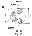
FIG. 3 is a cross-sectional view of a cord of the band of the tire shown inFIG. 1 ; -
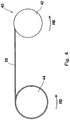
FIG. 4 is a schematic diagram illustrating a state where the band is formed; -
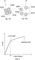
FIG. 5A is a cross-sectional view of the cord of the band of the tire, shown inFIG. 1 , to which tensile force is applied; -
FIG. 5B is a cross-sectional view of the cord of the band of the tire, shown inFIG. 1 , to which compressive force is applied; -
FIG. 6 shows a graph representing a relationship between tensile force and strain for the cord of the band of the tire shown inFIG. 1 ; -
FIG. 7 shows a graph representing a relationship between compressive force and strain for the cord of the band of the tire shown inFIG. 1 ; and -
FIG. 8 is a cross-sectional view of a cord of a band of a pneumatic tire according to another embodiment of the present invention. - The following will describe in detail the present invention based on preferred embodiments with reference where appropriate to the accompanying drawing.
-
FIG. 1 shows a pneumatic tire 2 according to one embodiment of the present invention. InFIG. 1 , the up-down direction represents the radial direction of the tire 2, the left-right direction represents the axial direction of the tire 2, and the direction perpendicular to the surface of the drawing sheet represents the circumferential direction of the tire 2. InFIG. 1 , an alternate long and short dash line CL represents the equator plane of the tire 2. The shape of the tire 2 is symmetric about the equator plane except for a tread pattern. - The tire 2 includes a
tread 4, a pair ofsidewalls 6, a pair ofbeads 8, acarcass 10, aninner liner 12, a pair ofchafers 14, and aband 16. The tire 2 is of a tubeless type. The tire 2 is mounted to a two-wheeled automotive vehicle. The tire 2 is mounted to a rear wheel of a two-wheeled automotive vehicle. - The
tread 4 has a shape that projects outward in the radial direction. Thetread 4 forms atread surface 18 that is brought into contact with a road surface. Thetread 4 hasgrooves 20 formed therein. A tread pattern is formed by thegrooves 20. Thetread 4 is formed from crosslinked rubber. For the crosslinked rubber of thetread 4, wear resistance, heat resistance, and grip performance are considered. - The tire 2 is mounted to a two-wheeled automotive vehicle. As shown in
FIG. 1 , in the tire 2, thetread surface 18 has a greatly curved outline. In the tire 2, a crown region mainly contacts with a road surface in straight running. A rider tilts the vehicle when the vehicle runs in cornering. Therefore, in the cornering, a shoulder region mainly contacts with a road surface. - Each
sidewall 6 extends almost inward from the end of thetread 4 in the radial direction. Thesidewall 6 is formed from crosslinked rubber that has excellent cut resistance and weather resistance. Thesidewall 6 prevents damage to thecarcass 10. - Each
bead 8 is disposed inward of thesidewall 6 in the radial direction. Eachbead 8 includes a core 22 and an apex 24. The core 22 is ring-shaped, and includes a wound non-stretchable wire. A typical material of the wire is steel. The apex 24 extends outward from the core 22 in the radial direction. The apex 24 is tapered outward in the radial direction. The apex 24 is formed from crosslinked rubber having a high hardness. - The
carcass 10 includes acarcass ply 26. In the tire 2, thecarcass 10 is formed from onecarcass ply 26. The carcass ply 26 is extended on and between thebeads 8 on both the sides, along thetread 4 and thesidewalls 6. The carcass ply 26 is turned up around the core 22 from the inner side toward the outer side in the axial direction. Thecarcass 10 may be formed from two or more carcass plies 26. - The carcass ply 26 has multiple cords aligned with each other, and topping rubber, which is not shown. An absolute value of an angle of each cord relative to the equator plane ranges from 75°to 90°. In other words, the
carcass 10 forms a radial structure. The cord is formed from an organic fiber. Preferable examples of the organic fiber include polyester fibers, nylon fibers, rayon fibers, polyethylene naphthalate fibers, and aramid fibers. - The
inner liner 12 is disposed inward of thecarcass 10. Theinner liner 12 is joined to the inner surface of thecarcass 10. Theinner liner 12 is formed from crosslinked rubber having excellent airtightness. A typical base rubber of theinner liner 12 is isobutylene-isoprene-rubber or halogenated isobutylene-isoprene-rubber. Theinner liner 12 maintains internal pressure of the tire 2. - Each
chafer 14 is disposed near thebead 8. When the tire 2 is mounted on a rim (not shown), thechafer 14 contacts with the rim. By the contact, a portion near thebead 8 is protected. In the present embodiment, thechafer 14 is formed from a fabric and rubber impregnated into the fabric. Thechafer 14 formed from crosslinked rubber may be used. - The
band 16 is disposed inward of thetread 4 in the radial direction. Theband 16 is disposed between thetread 4 and thecarcass 10 in the radial direction. Theband 16 extends along thecarcass 10 from one of the end sides of thetread surface 18 to the other of the end sides thereof. - The tire 2 may have a belt between the
band 16 and thecarcass 10, which is not shown. The belt includes an inner layer and an outer layer. Each layer has multiple cords aligned with each other, and topping rubber. The belt may be formed only from the inner layer. - As described below, the
band 16 is formed by a strip-shapedply 28 being wound.FIG. 2 shows the strip-shapedply 28. As shown inFIG. 2 , the strip-shapedply 28 includescords 32 and a toppingrubber 34 that covers thecords 32. The strip-shapedply 28 includes fivecords 32. Thecords 32 are aligned parallel to each other in the width direction of the strip-shapedply 28. The number of thecords 32 included in the strip-shapedply 28 may be not greater than four, or may be not less than six. The number of thecords 32 included in the strip-shapedply 28 is determined as appropriate in consideration of the specifications of the tire 2, productivity, or the like. As shown inFIG. 2 , eachcord 32 has a single-stranded structure in which a plurality offilaments 36 are stranded. In the embodiment shown inFIG. 2 , thecord 32 includes fourfilaments 36. The material of thefilament 36 is steel. As shown inFIG. 2 , a gap is formed between thefilaments 36. In other words, thefilaments 36 are "loosely" wound. - The
band 16 is formed by the strip-shapedply 28 being helically wound. Therefore, theband 16 includes thecords 32 that are helically wound. Theband 16 has a so-called jointless structure. An angle of thecord 32 relative to the circumferential direction is not greater than 15°. -
FIG. 3 shows a cross-section of thecord 32 included in theband 16. Eachcord 32 is formed from the fourfilaments 36. Therefore, the cross-section of thecord 32 includescross-sections 38 of the fourfilaments 36. Thefilaments 36 are loosely wound. Therefore, also in the cross-section of thecord 32 of theband 16, a gap is formed between thecross-sections 38 of thefilaments 36. - In
FIG. 3 , a circle E indicated by an alternate long and two short dashes line represents the smallest circle that surrounds thecross-sections 38 of thefilaments 36. A double-headed arrow ϕ represents the diameter of the circle E. A double-headed arrow ψ represents the diameter of onefilament 36. In theband 16, the gap is formed between thefilaments 36 such that the diameter ϕ is not less than three times the diameter ψ and not greater than six times the diameter ψ. - In the present invention, the diameter ϕ is measured in the following manner. That is, the tire 2 is cut in the direction perpendicular to the extending direction of the
cord 32 at an arbitrarily selected position, and the diameters of the circles E are measured for all the cross-sections of thecords 32 that are in the cross-section of theband 16. The average of the diameters is determined as the diameter ϕ. - In the tire 2, the
band 16 includes a center portion C and a pair of side portions S. Theband 16 is formed from the center portion C and the pair of side portions S. The center portion C is disposed at the center portion, in the axial direction, of theband 16. Each side portion S is disposed outward of the center portion C in the axial direction. InFIG. 1 , reference character CS represents a boundary between the center portion C and the side portion S. - In the tire 2, an initial elongation of the
cord 32 at the center portion C and an initial elongation thereof at the side portion S are different from each other. In the present embodiment, the initial elongation of thecord 32 at the center portion C is less than the initial elongation thereof at the side portion S. The initial elongation of thecord 32 at one of the side portions S and the initial elongation thereof at the other of the side portions S are the same. In the tire 2, the initial elongation of thecord 32 is not less than 0.1% and not greater than 1.5%. That is, the initial elongation at the center portion C is not less than 0.1%, and the initial elongation at the side portion S is not greater than 1.5%. - In the present invention, the initial elongation of the
cord 32 is specified by tensile test for thecord 32 by using a commercially available tensile testing machine in compliance with "JIS G3510". Specifically, a change amount of elongation obtained when load changes from 5N to 20N in the tensile test for thecord 32 taken from theband 16 of the tire 2 under the following measurement conditions, is measured as the initial elongation. - Grip distance: 250 mm
- Tension speed: 50 mm/min
- Measurement temperature: 23°C
- A method for producing the tire 2 includes a step of obtaining a raw cover and a step of vulcanizing the raw cover. In the step of obtaining a raw cover, a plurality of components of the tire 2 are assembled to form the raw cover. The step of obtaining the raw cover further includes a step of forming the
band 16. - In the step of forming the
band 16, as described above, the strip-shapedply 28 is helically wound.FIG. 4 shows a state where theband 16 is being formed. A former 40 is used for forming theband 16. - The former 40 includes a
bobbin 42 and adrum 44. Thebobbin 42 can rotate in the direction indicated by an arrow RB. A speed at which thebobbin 42 rotates can be changed by not-illustrated means. The strip-shapedply 28 is wound on thebobbin 42. Thedrum 44 can rotate in the direction indicated by an arrow RD. In the former 40, a speed at which thedrum 44 rotates can be changed by not-illustrated means. In a not-illustrated step before the step of forming theband 16, the carcass ply 26 is layered over the outer surface of thedrum 44. - In the step of forming the
band 16, the strip-shapedply 28 wound on thebobbin 42 is fed onto thedrum 44. The strip-shapedply 28 is wound onto thecarcass ply 26. In the producing of the tire 2, thedrum 44 is rotated at a constant speed. By adjusting a speed at which thebobbin 42 rotates, tension to be applied to the strip-shapedply 28 is controlled. The tension exerts an influence on an initial elongation of thecord 32 included in the strip-shapedply 28. When tension to be applied is increased, the initial elongation of thecord 32 can be decreased. When tension to be applied is decreased, the initial elongation of thecord 32 can be increased. - In this step, one strip-shaped
ply 28 is wound from a position corresponding to one of ends of theband 16 to a position corresponding to the other of the ends of theband 16. At this time, low tension is applied to the strip-shapedply 28 from the position corresponding to the one of the ends of theband 16 to a position corresponding to one of the boundaries CS. High tension is applied to the strip-shapedply 28 from the position corresponding to the one of the boundaries CS to a position corresponding to the other of the boundaries CS. Low tension is applied to the strip-shapedply 28 from the position corresponding to the other of the boundaries CS to the position corresponding to the other of the ends of theband 16. Thus, theband 16 in which the initial elongation of thecord 32 at the center portion C is less than the initial elongation thereof at the side portion S, can be obtained. This is the end of the step of forming theband 16. - The method for winding the strip-shaped
ply 28 is not limited to the above-described method. The former 40 may have twobobbins 42, and two strip-shapedplies 28 fed from thebobbins 42, respectively, may be wound to form theband 16. At this time, one of the strip-shapedplies 28 is wound toward the center from a position corresponding to one of ends of theband 16, and the other of the strip-shapedplies 28 is wound from a position corresponding to the center of theband 16 toward a position corresponding to the other of the ends of theband 16. Each of the strip-shapedplies 28 may be wound outward from the position corresponding to the center of theband 16. - When the step of forming the
band 16 is ended, thetread 4 is layered on the outer side of theband 16. Thus, a raw cover is obtained. This is the end of the step of obtaining the raw cover. - In the step of vulcanizing the raw cover, the raw cover is put into a mold (not shown). The outer surface of the raw cover contacts with a cavity surface of the mold. The inner surface of the raw cover contacts with a bladder or a rigid core 22 (also referred to as core). The raw cover is pressurized and heated in the mold. By the pressurizing and heating, rubber composition of the raw cover flows. Crosslinking reaction occurs in the rubber by the heating, to obtain the tire 2.
- Advantageous effects of the present invention will be described below.
- In the pneumatic tire 2 according to the present invention, the
cord 32 of theband 16 has a single-stranded structure in which thefilaments 36 formed from steel are stranded. Cost of thecord 32 having the single-stranded structure is low. In the tire 2, cost reduction can be achieved. - The
cord 32 of theband 16 of the tire 2 has a gap between thefilaments 36 such that the diameter ϕ of the smallest circle that surrounds thecross-sections 38 of thefilaments 36 is not less than three times the diameter ψ of thefilament 36 and not greater than six times the diameter ψ of thefilament 36. Thecord 32 is "loosely" stranded. Thecord 32 is flexible. Thecord 32 can be flexibly bent.FIG. 5A shows the cross-section of thecord 32 to which tensile force is applied. When tensile force is applied, thefilaments 36 that are loosely stranded are brought into close contact with each other, whereby thecord 32 is extended. Thecord 32 has an elongation higher than a conventional single-stranded cord. Thecord 32 that is flexible and has a high elongation contributes to good ride comfort. The tire 2 provides excellent ride comfort. -
FIG. 5B shows the cross-section of thecord 32 to which compressive force is applied. When compressive force is applied, a distance between thefilaments 36 that are loosely stranded is likely to be increased. Since a gap is formed between thecross-sections 38 of thefilaments 36, when compressive force is applied, the diameter of thefilament 36 is likely to change. Compression stiffness of thecord 32 is reduced. The tire 2 can be flexibly deformed even when high compressive force is applied to theband 16. Abrupt change of stiffness feeling of the tire 2 caused by buckling is inhibited. The tire 2 has excellent resistance to buckling. - The diameter ϕ of the
cord 32 is not greater than six times the diameter ψ of thefilament 36. The diameter ϕ of thecord 32 is appropriately maintained. Therefore, in theband 16, thecord 32 can have a sufficient density. Theband 16 has a sufficient binding force. This contributes to high-speed stability. Furthermore, to maintain appropriate diameter ϕ of thecord 32 contributes to maintain appropriate thickness of theband 16. This inhibits the mass of the tire 2 from increasing. - As described above, compression stiffness of the
cord 32 is reduced. Thecord 32 can be deformed so as to follow the magnitude of compressive force. Theband 16 is linearly deformed with respect to compressive force. This contributes to ride comfort and steering stability. The tire 2 can provide excellent ride comfort and steering stability. - As described above, when tensile force is applied to the
cord 32, thefilaments 36 that are loosely stranded are brought into close contact with each other. At this time, rubber in the gaps between thefilaments 36 is gotten caught between thefilaments 36. This contributes to good "endurance feeling" when the tire 2 is under a high load. -
FIG. 6 shows a graph representing a relationship between tensile force applied to thecord 32 and strain of thecord 32. A change rate (slope) of the strain to tensile force is great until thefilaments 36 that are loosely stranded come into close contact with each other, when tensile force is applied. After close contact occurs in thecord 32, the strain of thefilaments 36 themselves is strain of thecord 32, so that the slope becomes small. A point at which the slope changes is referred to as a close point. Specifically, a point at which the slope is reduced by 70% with respect to the slope between tensile force of 5N and tensile force of 20N, is the close point. - A tensile force Cp to the
cord 32 at the close point is preferably not less than 30N. When the tensile force Cp at the close point is not less than 30N in thecord 32, thecord 32 is flexible and has a high elongation. Thecord 32 effectively contributes to ride comfort. The tire 2 provides excellent ride comfort. - In the present invention, the close point is specified by tensile test for the
cord 32 by using a commercially available tensile testing machine in compliance with "JIS G3510". Specifically, the tensile test for thecord 32 taken from theband 16 of the tire 2 is performed under the following measurement conditions. The close point is calculated based on the graph, shown inFIG. 6 , obtained by measuring strain from load of 0N until thecord 32 is broken. - Grip distance: 250 mm
- Tension speed: 50 mm/min
- Measurement temperature: 23°C
-
FIG. 7 shows a graph representing a relationship between compressive force applied to thecord 32 and strain of thecord 32. In a region in which the applied compressive force is low, the distance between thefilaments 36 that are loosely stranded, and the diameter of thefilament 36 increase, so the slope is great. When the compressive force becomes high, the increase of the distance and diameter becomes small, and the slope also becomes small. Thecord 32 eventually yields. - A compressive force Bp at a time when the
cord 32 yields is preferably not less than 150N. When the compressive force Bp at a time when thecord 32 yields is not less than 150N, thecord 32 can be flexibly deformed with respect to a high compressive force. This effectively contributes to resistance to buckling. The tire 2 has excellent resistance to buckling. - In the present invention, the compressive force Bp at a time when the
cord 32 yields is specified by compression test for thecord 32 with the use of a commercially available compression testing machine. Specifically, the compression test for thecord 32 taken from theband 16 of the tire 2 is performed under the following measurement conditions. - Grip distance: 250 mm
- Compression speed: 50 mm/min
- Measurement temperature: 23°C
- In the tire 2, the initial elongation of the
cord 32 is not less than 0.1%. When the initial elongation of thecord 32 is not less than 0.1%, stiffness of thecord 32 is appropriately reduced. The tire 2 provides excellent ride comfort and has excellent impact absorption. Furthermore, appropriate reduction of stiffness of thecord 32 contributes to inhibition of buckling. Moreover, when the initial elongation is thus set, compressive force required for thecord 32 to yield can be increased. The tire 2 has excellent resistance to buckling. In these viewpoints, the initial elongation of thecord 32 is more preferably not less than 0.4%. - In the tire 2, the initial elongation of the
cord 32 is not higher than 1.5%. When the initial elongation of thecord 32 is not higher than 1.5%, thecord 32 effectively contributes to binding force of theband 16. The tire 2 has excellent high-speed stability. In this viewpoint, the initial elongation of thecord 32 is more preferably not higher than 1.0%. - In the
band 16, the initial elongation of thecord 32 is appropriately adjusted. In thecord 32, the initial elongation of the center portion C is different from the initial elongation of the side portion S. When each of the initial elongation of the center portion C and the initial elongation of the side portion S is thus adjusted, the tire 2 can exhibit required performance. - In
FIG. 1 , a double-headed arrow WB represents a distance, in the axial direction, from the equator plane CL to the outer side end of theband 16. A double-headed arrow WC represents a distance, in the axial direction, from the equator plane CL to the boundary CS between the center portion C and the side portion S. A ratio (WC/WB) of the distance WC to the distance WB is preferably not less than 30% and preferably not greater than 70%. When the ratio (WC/WB) is not less than 30% and not greater than 70%, and the initial elongation of the center portion C and the initial elongation of the side portion S are each adjusted, the tire 2 can exhibit required performance. - In the
band 16 of the present embodiment, as described above, the initial elongation of thecord 32 at the center portion C is less than the initial elongation thereof at the side portion S. In other words, the stiffness of the side portion S is lower than the stiffness of the center portion C. In a two-wheeled automotive vehicle, a rider tilts the vehicle at cornering. At this time, an outer side portion, in the radial direction, of the side portion S in thetread 4 mainly contacts with the ground. In the tire 2, the more greatly the rider tilts the vehicle, the lower stiffness feeling is. This contributes to ground contact feeling at cornering. The tire 2 provides excellent ground contact feeling at cornering. The center portion C having stiffness higher than the side portion S contributes to high speed stability during straight running. The tire 2 can have good high-speed stability during straight running. - The initial elongation of the
cord 32 at the center portion C may be higher than the initial elongation thereof at the side portion S. At this time, stiffness of the side portion S is higher than stiffness of the center portion C. In the tire 2, the more greatly a rider tilts the vehicle, the higher stiffness feeling is. This contributes to improvement of traction for leaving a corner. The center portion C having stiffness lower than the side portion S contributes to ride comfort during straight running. The tire 2 can provide good ride comfort during straight running. - The initial elongation of the
cord 32 at the center portion C may be the same as the initial elongation thereof at the side portion S depending on performance required for the tire 2. - In the
band 16, the diameter ψ of thefilament 36 is preferably not less than 0.15 mm and preferably not greater than 0.35 mm. When the diameter ψ is not less than 0.15 mm, thecord 32 has sufficient stiffness and durability. When the diameter ψ is not greater than 0.35 mm, thefilament 36 contributes to achievement of flexibility of thecord 32. - In the present invention, the dimensions and angles of the components of the tire 2 are measured in a state where the tire 2 is mounted on a normal rim (not shown), and inflated with air to a normal internal pressure, unless otherwise specified. During the measurement, no load is applied to the tire 2. In the description herein, the normal rim represents a rim that is specified according to the standard with which the tire 2 complies. The "standard rim" in the JATMA standard, the "Design Rim" in the TRA standard, and the "Measuring Rim" in the ETRTO standard are included in the normal rim. In the description herein, the normal internal pressure represents an internal pressure that is specified according to the standard with which the tire 2 complies. The "maximum air pressure" in the JATMA standard, the "maximum value" recited in "TIRE LOAD LIMITS AT VARIOUS COLD INFLATION PRESSURES" in the TRA standard, and the "INFLATION PRESSURE" in the ETRTO standard, are included in the normal internal pressure. These apply to a tire described below.
- In the above-described embodiment, an exemplary case where the number N of the
filaments 36 of thecord 32 is four, is described. The number N of filaments of a cord is not less than 3 and not greater than 6. It may vary depending on tires. The number N of filaments is determined according to performance required for the tire and cost. For example, when low cost is required for a tire, the number N of filaments is three or four. For a tire to which high load is applied, the number N of filaments is five or six. -
FIG. 8 shows a cross-section of acord 54 having threefilaments 52. Also in a band having thecord 54, a gap is formed between thefilaments 52 such that the diameter ϕ is not less than three times the diameter ψ and not greater than six times the diameter ψ. - In a
tire 50 of the present embodiment, thecord 54 of the band has a single-stranded structure in which thefilaments 52 formed from steel are stranded. Cost of thecord 54 having a single-stranded structure is low. In thetire 50, cost can be made low. - A gap is formed between the
filaments 52 in thecord 54 of the band of thetire 50. Thecord 54 is "loosely" stranded. Thecord 54 is flexible. Thecord 54 has an elongation higher than a conventional cord. Thecord 54 that is flexible and has a high elongation contributes to good ride comfort. Thetire 50 provides excellent ride comfort. - When compressive force is applied, a distance between the
filaments 52 that are loosely stranded is likely to be increased. Since a gap is formed between the cross-sections of thefilaments 52, when compressive force is applied, the diameter of thefilament 52 is likely to change. In thecord 54, compression stiffness is reduced. Thetire 50 can be flexibly deformed even when high load is applied to the band. Abrupt change of stiffness feeling of thetire 50 caused by buckling is inhibited. Thetire 50 has excellent resistance to buckling. - When the number of filaments is five or six, a gap is formed between the filaments such that the diameter ϕ is not less than 3.5 times the diameter ψ and not greater than 7 times the diameter ψ, which is not shown. Also in this tire, cost can be made low. This tire can also provide good ride comfort and have good resistance to buckling.
- A tire shown in
FIG. 1 was produced. The size of the tire was 190/55R17. The specifications of the cord of the tire are indicated in Table 1. The cord had a single-stranded structure including four filaments. This is indicated as "1×4" in the cell of "cord structure". The diameter ψ of the filament of the cord was 0.25 mm. In this tire, a ratio (WC/WB) of the distance WC to the distance WB was 40%. - A tire of comparative example 1 was obtained in the same manner as for example 1 except that the ratio (ϕ/ψ) and the initial elongations were as indicated in Table 1. In the tire, the filaments of the cord were tightly wound. A gap between the cords was the same as for example 1. This was a conventional tire.
- A tire of example 2 was obtained in the same manner as for example 1 except that the ratio (ϕ/ψ) was as indicated in Table 1.
- Tires of examples 3 to 4 were each obtained in the same manner as for example 1 except that the initial elongations were as indicated in Table 1.
- A tire of example 5 was obtained in the same manner as for example 1 except that the structure of the cord was as indicated in Table 1.
- Each of the tires was mounted on a normal rim (rim size=MT6.00), and mounted to a rear wheel of a sport-type two-wheeled automotive vehicle having an engine displacement of 1000 cc. The tire was inflated with air to an internal pressure of 290 kPa. A commercially available tire (size: 120/70R17) was mounted to a front wheel. The two-wheeled automotive vehicle was caused to run in a circuit course and a city area having asphalt road surfaces, and sensory evaluation was made by the rider. The evaluated items were ride comfort and resistance to buckling. The results are each indicated in Table 1 as an index with the result of comparative example 1 being 100. The greater the value of the index is, the more excellent each of ride comfort and resistance to buckling is. The greater the value is, the better the evaluation is.
- The mass of each tire was measured. The reciprocal of the resultant value is indicated in Table 1 as an index with the index of comparative example 1 being 100. The greater the value of the index is, the less the mass is. The greater the value is, the better the evaluation is.
- Cost required for forming the band was calculated. The reciprocal of the resultant value is indicated in Table 1 as an index with the index of comparative example 1 being 100. The greater the value of the index is, the less the cost is. The greater the value is, the better the evaluation is.
Table 1 Evaluation result Comparative example 1 Example 1 Example 2 Example 3 Example 4 Example 5 Cord structure 1x4 1x4 1x4 1x4 1x4 1x3 Ratio (ϕ/ψ) 2.5 3.0 6.0 3.0 3.0 3.0 Initial elongation of center portion [%] 0.2 0.4 0.4 1.0 1.5 0.4 Initial elongation of side portion [%] 0.2 0.5 0.5 1.0 1.5 0.5 Ride comfort 100 120 115 110 105 105 Resistance to buckling 100 110 115 115 120 105 Weight 100 105 90 105 105 110 Cost 100 100 95 100 100 95 - As indicated in Table 1, the tires of examples are comprehensively excellent. The evaluation result clearly indicates that the present invention is superior.
- The technique for the band described above is applicable to various tires.
Claims (6)
- A pneumatic tire (2, 50) comprising:a tread (4); anda band (16) disposed inward of the tread (4) in a radial direction, whereinthe band (16) includes a cord (32, 54) that is helically wound,
characterized in thatthe cord (32, 54) has a single-stranded structure in which filaments (36, 52) formed from steel are stranded, and the number of the filaments (36, 52) is not less than three and not greater than six,in a cross-section perpendicular to a direction in which the cord (32, 54) extends,when ϕ represents a diameter of a smallest circle (E) that surrounds cross-sections (38) of the filaments (36, 52), and ψ represents a diameter of each filament (36, 52),a gap is formed between the filaments (36, 52) such that the diameter ϕ is not less than three times the diameter ψ and not greater than six times the diameter ψ in the case of the number of the filaments (36, 52) being three or four,a gap is formed between the filaments (36, 52) such that the diameter ϕ is not less than 3.5 times the diameter ψ and not greater than seven times the diameter ψ in the case of the number of the filaments (36, 52) being five or six, andan initial elongation of the cord (32, 54) is not less than 0.1% and not greater than 1.5%, whereby a change amount of elongation obtained when load changes from 5N to 20N in a tensile test for the cord (32, 54) is measured as the initial elongation, taken from the band (16) of the tire (2, 50) under the following measurement conditions:- Grip distance: 250 mm- Tension speed: 50 mm/min- Measurement temperature: 23°C. - The pneumatic tire (2, 50) according to claim 1, wherein the diameter ψ of the filament (36, 52) is not less than 0.15 mm and not greater than 0.35 mm.
- The pneumatic tire (2, 50) according to claim 1, wherein a tensile force (Cp) to the cord (32, 54) at a close point is not less than 30N, whereby the close point is specified by tensile test for the cord (32, 54) taken from the band (16) of the tire (2, 50) performed under the following measurement conditions:- Grip distance: 250 mm- Tension speed: 50 mm/min- Measurement temperature: 23°C,and whereby the close point is a point at which a slope of the strain to tensile force is reduced by 70% with respect to a slope between tensile force of 5N and tensile force of 20N.
- The pneumatic tire (2, 50) according to claim 1, wherein a compressive force (Bp) at a time when the cord (32, 54) yields is not less than 150N, whereby the compressive force (Bp) at a time when the cord (32, 54) yields is specified by compression test for the cord (32) taken from the band (16) of the tire (2, 50) performed under the following measurement conditions.- Grip distance: 250 mm- Compression speed: 50 mm/min- Measurement temperature: 23°C.
- The pneumatic tire (2, 50) according to claim 1, wherein
the band (16) includes a center portion (C), and a pair of side portions (S) disposed outward of the center portion (C) in an axial direction, and
an initial elongation of the cord (32, 54) at the center portion (C) and an initial elongation of the cord (32, 54) at the side portion (S) are different from each other. - The pneumatic tire (2, 50) according to claim 1, wherein an angle of the cord (32, 54) relative to a circumferential direction of the tire (2, 50) is not greater than 15°.
Applications Claiming Priority (1)
| Application Number | Priority Date | Filing Date | Title |
|---|---|---|---|
| JP2018029567A JP7102770B2 (en) | 2018-02-22 | 2018-02-22 | Pneumatic tires |
Publications (3)
| Publication Number | Publication Date |
|---|---|
| EP3530485A1 EP3530485A1 (en) | 2019-08-28 |
| EP3530485B1 true EP3530485B1 (en) | 2020-08-26 |
| EP3530485B2 EP3530485B2 (en) | 2023-11-01 |
Family
ID=64665515
Family Applications (1)
| Application Number | Title | Priority Date | Filing Date |
|---|---|---|---|
| EP18212504.7A Active EP3530485B2 (en) | 2018-02-22 | 2018-12-14 | Pneumatic tire |
Country Status (4)
| Country | Link |
|---|---|
| US (1) | US20190255886A1 (en) |
| EP (1) | EP3530485B2 (en) |
| JP (1) | JP7102770B2 (en) |
| CN (1) | CN110182001A (en) |
Families Citing this family (4)
| Publication number | Priority date | Publication date | Assignee | Title |
|---|---|---|---|---|
| RU201339U1 (en) * | 2019-11-05 | 2020-12-15 | Общество с ограниченной ответственностью "Нижнекамский завод грузовых шин" | Breaker of a tire of a cargo pneumatic tire 9.00 Р 20 |
| RU2738624C1 (en) * | 2019-11-05 | 2020-12-15 | Общество с ограниченной ответственностью "Нижнекамский завод грузовых шин" | Cargo pneumatic tire breaker |
| JP2022017941A (en) * | 2020-07-14 | 2022-01-26 | 住友ゴム工業株式会社 | tire |
| JP2023073084A (en) * | 2021-11-15 | 2023-05-25 | 住友ゴム工業株式会社 | pneumatic tire |
Citations (5)
| Publication number | Priority date | Publication date | Assignee | Title |
|---|---|---|---|---|
| EP1213159A2 (en) | 2000-12-08 | 2002-06-12 | Bridgestone Corporation | Motorcycle tires and method of producing the same |
| WO2002051652A1 (en) | 2000-12-27 | 2002-07-04 | Pirelli Pneumatici S.P.A. | Reinforced tyre |
| US20050241741A1 (en) | 2000-05-22 | 2005-11-03 | Bridgestone Corporation | Steel cord for the reinforcement of rubber articles, rubber-steel cord composite body, radial tire, motorcycle radial tire and tire |
| US20100218872A1 (en) | 2006-01-20 | 2010-09-02 | Bridgestone Corporation | Rubber-steel cord composite and tire using the same |
| CN206646324U (en) | 2016-06-06 | 2017-11-17 | 贝卡尔特公司 | A kind of open type steel cord |
Family Cites Families (14)
| Publication number | Priority date | Publication date | Assignee | Title |
|---|---|---|---|---|
| JPH06346386A (en) * | 1993-06-02 | 1994-12-20 | Sumitomo Electric Ind Ltd | Metallic cord for reinforcing rubber article |
| JP2001032184A (en) * | 1999-05-20 | 2001-02-06 | Bridgestone Corp | Steel wire for reinforcing rubber article and excellent in endurance, rubber with steel cord composite material and pneumatic tire |
| EP1961860A4 (en) * | 2005-10-31 | 2010-02-17 | Bridgestone Corp | Steel cord for reinforcing rubber article and pneumatic radial tire |
| JP4848944B2 (en) * | 2006-12-01 | 2011-12-28 | 横浜ゴム株式会社 | Steel cord for rubber reinforcement and pneumatic radial tire using the same |
| JP4769228B2 (en) * | 2007-06-01 | 2011-09-07 | 住友ゴム工業株式会社 | Run flat tire |
| JP2012140718A (en) | 2010-12-28 | 2012-07-26 | Sumitomo Rubber Ind Ltd | Single line steel cord/rubber composite material and pneumatic tire |
| JP5432980B2 (en) * | 2011-12-22 | 2014-03-05 | 住友ゴム工業株式会社 | Pneumatic tire |
| JP6285267B2 (en) * | 2014-04-18 | 2018-02-28 | 株式会社ブリヂストン | tire |
| JP6378571B2 (en) * | 2014-07-30 | 2018-08-22 | 住友ゴム工業株式会社 | Pneumatic tire |
| DE102014226119A1 (en) * | 2014-12-16 | 2016-06-16 | Continental Reifen Deutschland Gmbh | Belt layer for a vehicle tire |
| FR3032150A1 (en) * | 2015-02-03 | 2016-08-05 | Michelin & Cie | RADIAL TIRE HAVING IMPROVED BELT STRUCTURE |
| JP6004045B1 (en) * | 2015-05-27 | 2016-10-05 | 横浜ゴム株式会社 | Pneumatic tire |
| JP6799420B2 (en) | 2016-08-26 | 2020-12-16 | サントリーホールディングス株式会社 | How to reduce gallate-type catechins in tea extract |
| JP6863000B2 (en) * | 2017-03-30 | 2021-04-21 | 住友ゴム工業株式会社 | Motorcycle tires |
-
2018
- 2018-02-22 JP JP2018029567A patent/JP7102770B2/en active Active
- 2018-12-14 EP EP18212504.7A patent/EP3530485B2/en active Active
-
2019
- 2019-01-15 CN CN201910035183.3A patent/CN110182001A/en active Pending
- 2019-02-05 US US16/267,605 patent/US20190255886A1/en not_active Abandoned
Patent Citations (5)
| Publication number | Priority date | Publication date | Assignee | Title |
|---|---|---|---|---|
| US20050241741A1 (en) | 2000-05-22 | 2005-11-03 | Bridgestone Corporation | Steel cord for the reinforcement of rubber articles, rubber-steel cord composite body, radial tire, motorcycle radial tire and tire |
| EP1213159A2 (en) | 2000-12-08 | 2002-06-12 | Bridgestone Corporation | Motorcycle tires and method of producing the same |
| WO2002051652A1 (en) | 2000-12-27 | 2002-07-04 | Pirelli Pneumatici S.P.A. | Reinforced tyre |
| US20100218872A1 (en) | 2006-01-20 | 2010-09-02 | Bridgestone Corporation | Rubber-steel cord composite and tire using the same |
| CN206646324U (en) | 2016-06-06 | 2017-11-17 | 贝卡尔特公司 | A kind of open type steel cord |
Non-Patent Citations (1)
| Title |
|---|
| "Testing methods for steel tire cords JIS G 3510", JAPANESE INDUSTRIAL STANDARD, 1992, XP055810719 |
Also Published As
| Publication number | Publication date |
|---|---|
| US20190255886A1 (en) | 2019-08-22 |
| JP2019142395A (en) | 2019-08-29 |
| JP7102770B2 (en) | 2022-07-20 |
| EP3530485B2 (en) | 2023-11-01 |
| EP3530485A1 (en) | 2019-08-28 |
| CN110182001A (en) | 2019-08-30 |
Similar Documents
| Publication | Publication Date | Title |
|---|---|---|
| EP3530485B1 (en) | Pneumatic tire | |
| EP3225427B1 (en) | Pneumatic tire and method for manufacturing pneumatic tire | |
| EP3421268B1 (en) | Tire for two-wheeled automotive vehicle | |
| EP3711978B1 (en) | Heavy duty pneumatic tire | |
| EP3178666B1 (en) | Tire for two-wheeled vehicles | |
| EP3354487B1 (en) | Pneumatic tire | |
| EP3189979B1 (en) | Pneumatic tire | |
| EP3202599B1 (en) | Pneumatic tire | |
| JP5145205B2 (en) | Pneumatic tire | |
| EP3366495B1 (en) | Tire for two-wheeled automotive vehicle | |
| EP3351406B1 (en) | Pneumatic tire | |
| EP2777948B1 (en) | Radial tire for motorcycle | |
| EP2492115B1 (en) | Radial tire for use in two-wheeled vehicle | |
| EP3842260B1 (en) | Motorcycle tyre | |
| US20230241922A1 (en) | Pneumatic tire | |
| JP6485907B2 (en) | Pneumatic tire | |
| EP3388253B1 (en) | Tire for two-wheeled automotive vehicle | |
| EP2551096B1 (en) | Pneumatic tire production method and tire | |
| EP3395589A1 (en) | Tire for two-wheeled automotive vehicle | |
| JP6848623B2 (en) | Pneumatic tires | |
| EP4296087A1 (en) | Motorcycle tire | |
| EP3228476B1 (en) | Pneumatic tire | |
| EP3398792B1 (en) | Tire for two-wheeled automotive vehicle | |
| US20230339267A1 (en) | Pneumatic tire | |
| JP2017001432A (en) | Pneumatic tire |
Legal Events
| Date | Code | Title | Description |
|---|---|---|---|
| PUAI | Public reference made under article 153(3) epc to a published international application that has entered the european phase |
Free format text: ORIGINAL CODE: 0009012 |
|
| STAA | Information on the status of an ep patent application or granted ep patent |
Free format text: STATUS: THE APPLICATION HAS BEEN PUBLISHED |
|
| AK | Designated contracting states |
Kind code of ref document: A1 Designated state(s): AL AT BE BG CH CY CZ DE DK EE ES FI FR GB GR HR HU IE IS IT LI LT LU LV MC MK MT NL NO PL PT RO RS SE SI SK SM TR |
|
| AX | Request for extension of the european patent |
Extension state: BA ME |
|
| STAA | Information on the status of an ep patent application or granted ep patent |
Free format text: STATUS: REQUEST FOR EXAMINATION WAS MADE |
|
| 17P | Request for examination filed |
Effective date: 20191119 |
|
| RBV | Designated contracting states (corrected) |
Designated state(s): AL AT BE BG CH CY CZ DE DK EE ES FI FR GB GR HR HU IE IS IT LI LT LU LV MC MK MT NL NO PL PT RO RS SE SI SK SM TR |
|
| GRAP | Despatch of communication of intention to grant a patent |
Free format text: ORIGINAL CODE: EPIDOSNIGR1 |
|
| STAA | Information on the status of an ep patent application or granted ep patent |
Free format text: STATUS: GRANT OF PATENT IS INTENDED |
|
| INTG | Intention to grant announced |
Effective date: 20200529 |
|
| GRAS | Grant fee paid |
Free format text: ORIGINAL CODE: EPIDOSNIGR3 |
|
| GRAA | (expected) grant |
Free format text: ORIGINAL CODE: 0009210 |
|
| STAA | Information on the status of an ep patent application or granted ep patent |
Free format text: STATUS: THE PATENT HAS BEEN GRANTED |
|
| AK | Designated contracting states |
Kind code of ref document: B1 Designated state(s): AL AT BE BG CH CY CZ DE DK EE ES FI FR GB GR HR HU IE IS IT LI LT LU LV MC MK MT NL NO PL PT RO RS SE SI SK SM TR |
|
| REG | Reference to a national code |
Ref country code: GB Ref legal event code: FG4D |
|
| REG | Reference to a national code |
Ref country code: CH Ref legal event code: EP |
|
| REG | Reference to a national code |
Ref country code: AT Ref legal event code: REF Ref document number: 1306030 Country of ref document: AT Kind code of ref document: T Effective date: 20200915 |
|
| REG | Reference to a national code |
Ref country code: IE Ref legal event code: FG4D |
|
| REG | Reference to a national code |
Ref country code: DE Ref legal event code: R096 Ref document number: 602018007286 Country of ref document: DE |
|
| REG | Reference to a national code |
Ref country code: LT Ref legal event code: MG4D |
|
| PG25 | Lapsed in a contracting state [announced via postgrant information from national office to epo] |
Ref country code: NO Free format text: LAPSE BECAUSE OF FAILURE TO SUBMIT A TRANSLATION OF THE DESCRIPTION OR TO PAY THE FEE WITHIN THE PRESCRIBED TIME-LIMIT Effective date: 20201126 Ref country code: BG Free format text: LAPSE BECAUSE OF FAILURE TO SUBMIT A TRANSLATION OF THE DESCRIPTION OR TO PAY THE FEE WITHIN THE PRESCRIBED TIME-LIMIT Effective date: 20201126 Ref country code: SE Free format text: LAPSE BECAUSE OF FAILURE TO SUBMIT A TRANSLATION OF THE DESCRIPTION OR TO PAY THE FEE WITHIN THE PRESCRIBED TIME-LIMIT Effective date: 20200826 Ref country code: GR Free format text: LAPSE BECAUSE OF FAILURE TO SUBMIT A TRANSLATION OF THE DESCRIPTION OR TO PAY THE FEE WITHIN THE PRESCRIBED TIME-LIMIT Effective date: 20201127 Ref country code: PT Free format text: LAPSE BECAUSE OF FAILURE TO SUBMIT A TRANSLATION OF THE DESCRIPTION OR TO PAY THE FEE WITHIN THE PRESCRIBED TIME-LIMIT Effective date: 20201228 Ref country code: LT Free format text: LAPSE BECAUSE OF FAILURE TO SUBMIT A TRANSLATION OF THE DESCRIPTION OR TO PAY THE FEE WITHIN THE PRESCRIBED TIME-LIMIT Effective date: 20200826 Ref country code: HR Free format text: LAPSE BECAUSE OF FAILURE TO SUBMIT A TRANSLATION OF THE DESCRIPTION OR TO PAY THE FEE WITHIN THE PRESCRIBED TIME-LIMIT Effective date: 20200826 Ref country code: FI Free format text: LAPSE BECAUSE OF FAILURE TO SUBMIT A TRANSLATION OF THE DESCRIPTION OR TO PAY THE FEE WITHIN THE PRESCRIBED TIME-LIMIT Effective date: 20200826 |
|
| REG | Reference to a national code |
Ref country code: NL Ref legal event code: MP Effective date: 20200826 |
|
| REG | Reference to a national code |
Ref country code: AT Ref legal event code: MK05 Ref document number: 1306030 Country of ref document: AT Kind code of ref document: T Effective date: 20200826 |
|
| PG25 | Lapsed in a contracting state [announced via postgrant information from national office to epo] |
Ref country code: IS Free format text: LAPSE BECAUSE OF FAILURE TO SUBMIT A TRANSLATION OF THE DESCRIPTION OR TO PAY THE FEE WITHIN THE PRESCRIBED TIME-LIMIT Effective date: 20201226 Ref country code: LV Free format text: LAPSE BECAUSE OF FAILURE TO SUBMIT A TRANSLATION OF THE DESCRIPTION OR TO PAY THE FEE WITHIN THE PRESCRIBED TIME-LIMIT Effective date: 20200826 Ref country code: PL Free format text: LAPSE BECAUSE OF FAILURE TO SUBMIT A TRANSLATION OF THE DESCRIPTION OR TO PAY THE FEE WITHIN THE PRESCRIBED TIME-LIMIT Effective date: 20200826 Ref country code: NL Free format text: LAPSE BECAUSE OF FAILURE TO SUBMIT A TRANSLATION OF THE DESCRIPTION OR TO PAY THE FEE WITHIN THE PRESCRIBED TIME-LIMIT Effective date: 20200826 Ref country code: RS Free format text: LAPSE BECAUSE OF FAILURE TO SUBMIT A TRANSLATION OF THE DESCRIPTION OR TO PAY THE FEE WITHIN THE PRESCRIBED TIME-LIMIT Effective date: 20200826 |
|
| PG25 | Lapsed in a contracting state [announced via postgrant information from national office to epo] |
Ref country code: SM Free format text: LAPSE BECAUSE OF FAILURE TO SUBMIT A TRANSLATION OF THE DESCRIPTION OR TO PAY THE FEE WITHIN THE PRESCRIBED TIME-LIMIT Effective date: 20200826 Ref country code: EE Free format text: LAPSE BECAUSE OF FAILURE TO SUBMIT A TRANSLATION OF THE DESCRIPTION OR TO PAY THE FEE WITHIN THE PRESCRIBED TIME-LIMIT Effective date: 20200826 Ref country code: RO Free format text: LAPSE BECAUSE OF FAILURE TO SUBMIT A TRANSLATION OF THE DESCRIPTION OR TO PAY THE FEE WITHIN THE PRESCRIBED TIME-LIMIT Effective date: 20200826 Ref country code: DK Free format text: LAPSE BECAUSE OF FAILURE TO SUBMIT A TRANSLATION OF THE DESCRIPTION OR TO PAY THE FEE WITHIN THE PRESCRIBED TIME-LIMIT Effective date: 20200826 Ref country code: CZ Free format text: LAPSE BECAUSE OF FAILURE TO SUBMIT A TRANSLATION OF THE DESCRIPTION OR TO PAY THE FEE WITHIN THE PRESCRIBED TIME-LIMIT Effective date: 20200826 |
|
| REG | Reference to a national code |
Ref country code: DE Ref legal event code: R026 Ref document number: 602018007286 Country of ref document: DE |
|
| PLBI | Opposition filed |
Free format text: ORIGINAL CODE: 0009260 |
|
| PG25 | Lapsed in a contracting state [announced via postgrant information from national office to epo] |
Ref country code: AT Free format text: LAPSE BECAUSE OF FAILURE TO SUBMIT A TRANSLATION OF THE DESCRIPTION OR TO PAY THE FEE WITHIN THE PRESCRIBED TIME-LIMIT Effective date: 20200826 Ref country code: AL Free format text: LAPSE BECAUSE OF FAILURE TO SUBMIT A TRANSLATION OF THE DESCRIPTION OR TO PAY THE FEE WITHIN THE PRESCRIBED TIME-LIMIT Effective date: 20200826 Ref country code: ES Free format text: LAPSE BECAUSE OF FAILURE TO SUBMIT A TRANSLATION OF THE DESCRIPTION OR TO PAY THE FEE WITHIN THE PRESCRIBED TIME-LIMIT Effective date: 20200826 |
|
| PLAX | Notice of opposition and request to file observation + time limit sent |
Free format text: ORIGINAL CODE: EPIDOSNOBS2 |
|
| 26 | Opposition filed |
Opponent name: COMPAGNIE GENERALE DES ETABLISSEMENTS MICHELIN Effective date: 20210521 |
|
| PG25 | Lapsed in a contracting state [announced via postgrant information from national office to epo] |
Ref country code: SK Free format text: LAPSE BECAUSE OF FAILURE TO SUBMIT A TRANSLATION OF THE DESCRIPTION OR TO PAY THE FEE WITHIN THE PRESCRIBED TIME-LIMIT Effective date: 20200826 |
|
| PG25 | Lapsed in a contracting state [announced via postgrant information from national office to epo] |
Ref country code: IT Free format text: LAPSE BECAUSE OF FAILURE TO SUBMIT A TRANSLATION OF THE DESCRIPTION OR TO PAY THE FEE WITHIN THE PRESCRIBED TIME-LIMIT Effective date: 20200826 |
|
| PG25 | Lapsed in a contracting state [announced via postgrant information from national office to epo] |
Ref country code: SI Free format text: LAPSE BECAUSE OF FAILURE TO SUBMIT A TRANSLATION OF THE DESCRIPTION OR TO PAY THE FEE WITHIN THE PRESCRIBED TIME-LIMIT Effective date: 20200826 Ref country code: MC Free format text: LAPSE BECAUSE OF FAILURE TO SUBMIT A TRANSLATION OF THE DESCRIPTION OR TO PAY THE FEE WITHIN THE PRESCRIBED TIME-LIMIT Effective date: 20200826 |
|
| REG | Reference to a national code |
Ref country code: BE Ref legal event code: MM Effective date: 20201231 |
|
| PLBB | Reply of patent proprietor to notice(s) of opposition received |
Free format text: ORIGINAL CODE: EPIDOSNOBS3 |
|
| PG25 | Lapsed in a contracting state [announced via postgrant information from national office to epo] |
Ref country code: IE Free format text: LAPSE BECAUSE OF NON-PAYMENT OF DUE FEES Effective date: 20201214 Ref country code: LU Free format text: LAPSE BECAUSE OF NON-PAYMENT OF DUE FEES Effective date: 20201214 |
|
| PG25 | Lapsed in a contracting state [announced via postgrant information from national office to epo] |
Ref country code: TR Free format text: LAPSE BECAUSE OF FAILURE TO SUBMIT A TRANSLATION OF THE DESCRIPTION OR TO PAY THE FEE WITHIN THE PRESCRIBED TIME-LIMIT Effective date: 20200826 Ref country code: MT Free format text: LAPSE BECAUSE OF FAILURE TO SUBMIT A TRANSLATION OF THE DESCRIPTION OR TO PAY THE FEE WITHIN THE PRESCRIBED TIME-LIMIT Effective date: 20200826 Ref country code: CY Free format text: LAPSE BECAUSE OF FAILURE TO SUBMIT A TRANSLATION OF THE DESCRIPTION OR TO PAY THE FEE WITHIN THE PRESCRIBED TIME-LIMIT Effective date: 20200826 |
|
| PG25 | Lapsed in a contracting state [announced via postgrant information from national office to epo] |
Ref country code: MK Free format text: LAPSE BECAUSE OF FAILURE TO SUBMIT A TRANSLATION OF THE DESCRIPTION OR TO PAY THE FEE WITHIN THE PRESCRIBED TIME-LIMIT Effective date: 20200826 |
|
| PG25 | Lapsed in a contracting state [announced via postgrant information from national office to epo] |
Ref country code: BE Free format text: LAPSE BECAUSE OF NON-PAYMENT OF DUE FEES Effective date: 20201231 |
|
| REG | Reference to a national code |
Ref country code: CH Ref legal event code: PL |
|
| PG25 | Lapsed in a contracting state [announced via postgrant information from national office to epo] |
Ref country code: LI Free format text: LAPSE BECAUSE OF NON-PAYMENT OF DUE FEES Effective date: 20211231 Ref country code: CH Free format text: LAPSE BECAUSE OF NON-PAYMENT OF DUE FEES Effective date: 20211231 |
|
| P01 | Opt-out of the competence of the unified patent court (upc) registered |
Effective date: 20230510 |
|
| GBPC | Gb: european patent ceased through non-payment of renewal fee |
Effective date: 20221214 |
|
| PUAH | Patent maintained in amended form |
Free format text: ORIGINAL CODE: 0009272 |
|
| STAA | Information on the status of an ep patent application or granted ep patent |
Free format text: STATUS: PATENT MAINTAINED AS AMENDED |
|
| PLAB | Opposition data, opponent's data or that of the opponent's representative modified |
Free format text: ORIGINAL CODE: 0009299OPPO |
|
| PG25 | Lapsed in a contracting state [announced via postgrant information from national office to epo] |
Ref country code: GB Free format text: LAPSE BECAUSE OF NON-PAYMENT OF DUE FEES Effective date: 20221214 |
|
| 27A | Patent maintained in amended form |
Effective date: 20231101 |
|
| AK | Designated contracting states |
Kind code of ref document: B2 Designated state(s): AL AT BE BG CH CY CZ DE DK EE ES FI FR GB GR HR HU IE IS IT LI LT LU LV MC MK MT NL NO PL PT RO RS SE SI SK SM TR |
|
| REG | Reference to a national code |
Ref country code: DE Ref legal event code: R102 Ref document number: 602018007286 Country of ref document: DE |
|
| R26 | Opposition filed (corrected) |
Opponent name: COMPAGNIE GENERALE DES ETABLISSEMENTS MICHELIN Effective date: 20210521 |
|
| PGFP | Annual fee paid to national office [announced via postgrant information from national office to epo] |
Ref country code: FR Payment date: 20231108 Year of fee payment: 6 Ref country code: DE Payment date: 20231031 Year of fee payment: 6 |