JP5145205B2 - Pneumatic tire - Google Patents
Pneumatic tire Download PDFInfo
- Publication number
- JP5145205B2 JP5145205B2 JP2008314263A JP2008314263A JP5145205B2 JP 5145205 B2 JP5145205 B2 JP 5145205B2 JP 2008314263 A JP2008314263 A JP 2008314263A JP 2008314263 A JP2008314263 A JP 2008314263A JP 5145205 B2 JP5145205 B2 JP 5145205B2
- Authority
- JP
- Japan
- Prior art keywords
- tire
- core
- bead
- wire
- cross
- Prior art date
- Legal status (The legal status is an assumption and is not a legal conclusion. Google has not performed a legal analysis and makes no representation as to the accuracy of the status listed.)
- Active
Links
Images


Description
本発明は、空気入りタイヤに関する。 The present invention relates to a pneumatic tire.
タイヤは、一対のビードと、両ビードの間に架け渡されたカーカスとを備えている。ビードは、コアと、エイペックスとを備えている。コアは、リング状であり、複数本の非伸縮性ワイヤーを含む。エイペックスは、このコアから半径方向外向きに延在している。エイペックスは、高硬度な架橋ゴムからなる。カーカスは、カーカスプライを備えている。カーカスプライは、通常はコアの周りで折り返される。 The tire includes a pair of beads and a carcass spanned between the two beads. The bead includes a core and an apex. The core is ring-shaped and includes a plurality of non-stretchable wires. The apex extends radially outward from the core. Apex is made of a highly hard crosslinked rubber. The carcass includes a carcass ply. The carcass ply is usually folded around the core.
図7は、従来のタイヤの製造状況の一部が示された模式図である。この図7には、フォーマー2と、カーカスプライ4と、コア6及びエイペックス8からなるビード10とが示されている。カーカスプライ4は、フォーマー2に巻き回されている。このカーカスプライ4に、ビード10が組み合わされている。このカーカスプライ4は、このビード10の周りで折り返されている。図示されていないが、このフォーマー2において、サイドウォール、トレッド等のような部材がアッセンブリーされ、ローカバー(未架橋タイヤとも称される)が形成される。このローカバーが、加硫工程においてモールドに投入され、タイヤが得られる。
FIG. 7 is a schematic view showing a part of the manufacturing situation of a conventional tire. FIG. 7 shows a former 2, a
タイヤがリムに組み込まれると、上記ビード10の近傍がリムに当接する。タイヤの性能向上の観点から、上記ビード10の構成について様々な検討がなされている。特開2001−97010公報に、ワイヤインサート、フリッパ等の追加補強部材を適用することなくビードワイヤ構体で構成することにより、ビードの剛性が調整されたタイヤが開示されている。このタイヤでは、ビードワイヤ構体の半径方向外側位置はリムライン位置と同一又は外側にある。
前述したように、従来の製造方法では、カーカスプライ4はビード10で折り返される。軽量化及び剛性制御の観点から、コア6の形状をそのままにして上記エイペックス8のサイズを小さくすると、カーカスプライ4が折り返される際に空間が形成され、このビード10に空気が巻き込まれてしまう。この場合、形成されたビード10に、空気が残存してしまう。このようなタイヤの品質は、十分ではない。エイペックス8のサイズを小さくするだけでは、軽量でしかも高品質なタイヤは得られない。
As described above, in the conventional manufacturing method, the
本発明の目的は、軽量でしかも操縦安定性に優れた高品質な空気入りタイヤの提供にある。 An object of the present invention is to provide a high-quality pneumatic tire that is lightweight and excellent in handling stability.
本発明に係る空気入りタイヤは、一対のビードを備えている。両ビードのそれぞれは、周方向に延在するワイヤーを含むコアを備えている。このコアのストランド数は、2以上である。このコアのターン数は、上記ストランド数の3倍以上である。このタイヤがフランジを有する正規リムに装着されたとき、上記ワイヤーの半径方向外側位置は、このフランジの半径方向外端よりも半径方向内側である。 The pneumatic tire according to the present invention includes a pair of beads. Each of the beads has a core including a wire extending in the circumferential direction. The number of strands of this core is 2 or more. The number of turns of the core is at least three times the number of strands. When the tire is mounted on a regular rim having a flange, the radially outer position of the wire is radially inner than the radially outer end of the flange.
好ましくは、このタイヤでは、上記ビードの断面積に対する上記ワイヤーの断面積の比率は70%以上である。 Preferably, in this tire, the ratio of the cross-sectional area of the wire to the cross-sectional area of the bead is 70% or more.
好ましくは、このタイヤでは、上記ストランド数は2である。 Preferably, in this tire, the number of strands is two.
好ましくは、このタイヤでは、上記ターン数は8である。 Preferably, in this tire, the number of turns is eight.
本発明に係る空気入りタイヤでは、コアに含まれているワイヤーは、ストランド数が2以上でありターン数がこのストランド数の3倍以上となるように整列されつつ、周方向に巻き回されている。このコアは、タイヤの剛性に適切に寄与しうる。このタイヤは、操縦安定性に優れる。このタイヤが正規リムに装着されたとき、ワイヤーの半径方向外側位置は、この正規リムのフランジの外端よりも半径方向内側にある。このタイヤは、旋回時における応答性にも優れる。このコアは、カーカスプライが折り返される際の空間形成を防止しうるから、ビードへの空気の巻き込みが抑制される。空気残り不良の発生が防止されうるから、このタイヤは高品質である。このタイヤでは、そのビードにエイペックスを設ける場合において、このエイペックスのサイズを小さくすることができる。このタイヤの構成部材から、エイペックスを除くことも可能である。このタイヤでは、軽量化が達成されうる。このようなタイヤは、生産性の向上に寄与しうる。 In the pneumatic tire according to the present invention, the wires included in the core are wound in the circumferential direction while being aligned so that the number of strands is two or more and the number of turns is three times or more of the number of strands. Yes. This core can appropriately contribute to the rigidity of the tire. This tire is excellent in handling stability. When the tire is mounted on the regular rim, the radially outer position of the wire is radially inward from the outer end of the flange of the regular rim. This tire is also excellent in responsiveness during turning. Since this core can prevent the formation of a space when the carcass ply is folded back, the entrainment of air into the bead is suppressed. This tire is of high quality because the occurrence of poor air residues can be prevented. In this tire, when an apex is provided on the bead, the size of the apex can be reduced. It is also possible to remove the apex from the constituent members of the tire. With this tire, weight reduction can be achieved. Such a tire can contribute to an improvement in productivity.
以下、適宜図面が参照されつつ、好ましい実施形態に基づいて本発明が詳細に説明される。 Hereinafter, the present invention will be described in detail based on preferred embodiments with appropriate reference to the drawings.
図1は、本発明の一実施形態に係る空気入りタイヤ12の一部が正規リム14とともに示された断面図である。図2は、図1の一部が示された拡大断面図である。この図1及び図2において、上下方向が半径方向であり、左右方向が軸方向であり、紙面との垂直方向が周方向である。このタイヤ12は、図1中の一点鎖線CLを中心としたほぼ左右対称の形状を呈する。この一点鎖線CLは、タイヤ12の赤道面を表す。図1及び図2において、タイヤ12は正規リム14(以下、リム14)に装着されている。このタイヤ12は、二輪自動車用である。このタイヤ12は、チューブレスタイプである。リム14は、軸方向に延在するビードシート16と、このビードシート16から半径方向外向きに延在するフランジ18とを有している。このリム14は、JATMA規格で規定されるMT型深底リムである。
FIG. 1 is a cross-sectional view showing a part of a
タイヤ12は、トレッド20、サイドウォール22、ビード24、カーカス26、ベルト28及びインナーライナー30を備えている。
The
トレッド20は、耐摩耗性に優れた架橋ゴムからなる。トレッド20は、半径方向外向きに凸な形状を呈している。トレッド20は、トレッド面32を備えている。このトレッド面32は、路面と接地する。トレッド面32には、溝34が刻まれている。この溝34により、トレッドパターンが形成されている。トレッド20に溝34が刻まれなくてもよい。
The
サイドウォール22は、トレッド20の端から半径方向略内向きに延びている。このサイドウォール22は、架橋ゴムからなる。サイドウォール22は、撓みによって路面からの衝撃を吸収する。さらにサイドウォール22は、カーカス26の外傷を防止する。
The
ビード24は、サイドウォール22よりも半径方向略内側に位置している。ビード24は、コア36からなる。このコア36は、リング状である。
The
コア36は、周方向に延在するワイヤー38とトッピングゴム40とからなる。このワイヤー38は、非伸縮性である。このワイヤー38の材質は、スチールである。
The
図示されているように、16のワイヤー38の断面が、軸方向に2列、半径方向に8段に整列されている。本明細書では、軸方向に並べられている上記断面の列数がコア36のストランド数と称される。このタイヤ12では、コア36のストランド数は2である。本明細書では、半径方向に並べられている上記断面の段数がコア36のターン数である。このタイヤ12では、コア36のターン数は8である。このタイヤ12では、上記コア36に含まれるワイヤー38の断面数は、ストランド数とターン数との積で示される。なお、図中、コア36に含まれるワイヤー38の半径方向外側位置が点PAとして示されている。
As shown in the drawing, the cross sections of the 16
このタイヤ12では、高硬度な架橋ゴムからなり半径方向に先細りな形状を呈するエイペックスは設けられていない。したがって、コア36の半径方向外側に位置する端42(以下、コア36の外端42)がビード24の外端44に相当する。なお、このビード24にエイペックスが設けられてもよい。この場合、このエイペックスがこのコア36の半径方向外側に配置されるから、このエイペックスの半径方向外側に位置する端がビード24の外端44に相当する。
The
カーカス26は、カーカスプライ46からなる。このカーカス26は、2枚以上のカーカスプライ46で構成されてもよい。図示されているように、カーカスプライ46は、両側のビード24の間に架け渡されており、トレッド20及びサイドウォール22の内側に沿っている。カーカスプライ46は、コア36の周りを、軸方向内側から外側に向かって折り返されている。このカーカスプライ46の端48は、上記コア36の外端42よりも半径方向外側に位置している。このカーカスプライ46の端48が、このコア36の外端42よりも半径方向内側に位置してもよい。
The
図示されていないが、カーカスプライ46は、並列された多数のコードとトッピングゴムとからなる。各コードが赤道面に対してなす角度の絶対値は、通常は70°から90°である。換言すれば、このカーカス26はラジアル構造を有する。コードは、通常は有機繊維からなる。好ましい有機繊維としては、ポリエステル繊維、ナイロン繊維、レーヨン繊維、ポリエチレンナフタレート繊維及びアラミド繊維が例示される。バイアス構造のカーカス26が採用されてもよい。
Although not shown, the carcass ply 46 includes a large number of cords arranged in parallel and a topping rubber. The absolute value of the angle formed by each cord with respect to the equator plane is usually 70 ° to 90 °. In other words, the
ベルト28は、カーカス26の半径方向外側に位置している。ベルト28は、カーカス26と積層されている。ベルト28は、カーカス26を補強する。ベルト28は、内側層50及び外側層52からなる。図示されていないが、内側層50及び外側層52のそれぞれは、並列された多数のコードとトッピングゴムとからなる。各コードは、赤道面に対して傾斜している。傾斜角度の絶対値は、10°以上35°以下である。内側層50のコードの傾斜方向は、外側層52のコードの傾斜方向とは逆である。コードの好ましい材質は、スチールである。コードに、有機繊維が用いられてもよい。なお、このタイヤ12では、高速安定性の向上の観点から、このベルト28の半径方向外側に、実質的に周方向に延在するコードを有するバンドが設けられてもよい。
The
インナーライナー30は、カーカス26の内周面に接合されている。インナーライナー30は、架橋ゴムからなる。インナーライナー30には、空気遮蔽性に優れたゴムが用いられている。インナーライナー30は、タイヤ12の内圧を保持する役割を果たす。
The
このタイヤ12では、上記コア36は複数のワイヤー38とトッピングゴム40とからなるリボンを用いて形成される。
In the
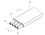
図3は、コア36の形成に用いられるリボン54の一部が示された断面斜視図である。この図3において、両矢印線Aはこのリボン54の長手方向を表しており、両矢印線Bはこのリボン54の幅方向を表している。図示されているように、このリボン54は、4本のワイヤー38を含んでいる。これらワイヤー38は、幅方向に等間隔で並べられている。これらワイヤー38のそれぞれは、長手方向に延在しており、トッピングゴム40に覆われている。このタイヤ12の製造方法では、ワイヤー38とトッピングゴム40とが押出機で押し出されてリボン54が形成された後、このリボン54が巻き回されリング状の積層体が形成される。
FIG. 3 is a cross-sectional perspective view showing a part of the
図4は、コア36の形成に用いられる積層体56の一部が示された断面斜視図である。この図3において、両矢印線Cはこの積層体56の周方向を表しており、両矢印線Dはこの積層体56の半径方向を表しており、両矢印線Bはこの積層体56の幅方向を表している。この積層体56の幅方向は、上記リボン54の幅方向と一致する。この積層体56において、上記リボン54は周方向に巻き回されている。前述したように、このリボン54に含まれるワイヤー38はこのリボン54の長手方向に延在しているから、この積層体56に含まれるワイヤー38も周方向に巻き回されている。図示されているように、この積層体56はこのリボン54が8回周巻きされ形成されている。
FIG. 4 is a cross-sectional perspective view showing a part of the
このタイヤ12の製造方法では、上記積層体56がその幅方向において半分に分割される。この分割により、ワイヤー38が整列されつつ周方向に巻き回されたコア36が形成される。このタイヤ12では、積層体56が半分に分割されてコア36が形成されているから、このコア36に含まれるワイヤー38の本数は2本である。なお、図4中、二点鎖線DLに沿った面が分割面である。
In the method for manufacturing the
このタイヤ12の製造方法では、上記コア36が他の方法で形成されてもよい。図5は、他の方法によるコア36の形成状況が示された模式図である。この図5には、コア36の形成用ドラム58が示されている。この図5において、左右方向が軸方向であり、上下方向が半径方向である。この紙面に対して垂直な方向が、周方向である。
In the
ドラム58は、本体60と、細径部62と、可動部64とを備えている。細径部62は、本体60の軸方向外側に位置している。この細径部62は、この本体60の外径よりも小さい外径を有している。この細径部62は、本体60と一体的に形成されている。可動部64は、この細径部62の軸方向外側に位置している。可動部64は、細径部62の外径よりも大きい外径を有している。可動部64の外径は、本体60の外径と同等である。可動部64は、軸方向に移動しうるように構成されている。このドラム58では、この可動部64が細径部62に当接することにより、この細径部62の部分に溝66が形成される。この溝66は、周方向に延在する。
The
上記ドラム58を用いてコア36が形成されるとき、1本のワイヤー38がトッピングゴム40で被覆されたコード68が準備される。このコード68が上記溝66に周巻きされ、そのストランド数が2であり、そのターン数が8であるコア36が形成される。この場合においても、ワイヤー38が整列されつつ周巻きされ、コア36が形成される。このコア36は、可動部64が軸方向外向きに動かされ、細径部62から取り出される。なお、2本のワイヤー38とトッピングゴム40とからなるリボンがこの溝66で周巻きされて、そのストランド数が2でありそのターン数が8であるコア36が形成されてもよい。
When the
上記のようにして形成されたコア36は、フォーマー2に供給される。このフォーマー2には、カーカスプライ46等のようなタイヤ12を構成する他の部材も供給される。
The core 36 formed as described above is supplied to the former 2. Other members constituting the
図6は、図1のタイヤ12の製造状況の一部が示された模式図である。この図6には、フォーマー2とカーカスプライ46とコア36とが示されている。この図6において、左右方向が軸方向であり、上下方向が半径方向である。この紙面に対して垂直な方向が、周方向である。
FIG. 6 is a schematic diagram showing a part of the manufacturing status of the
フォーマー2は、本体70と、可動部72とを備えている。図示されていないが、本体70は、複数のセグメントからなり、拡径しうるように構成されている。可動部72は、本体70の軸方向外側に位置している。可動部72は、本体70の外径よりも小さな外径を有している。この可動部72は、本体70が拡径すると、軸方向内向きに動くように構成されている。
The former 2 includes a
この製造方法では、フォーマー2に巻かれたカーカスプライ46に、上記コア36が組み合わされる。次いで、このカーカスプライ46が、このコア36で折り返される。
In this manufacturing method, the
図6において、点PBは加硫工程前にあるコア36の半径方向外側位置を表している。点PCは、加硫工程前にあるコア36に含まれるワイヤー38の半径方向外側位置を表している。図示されているように、この半径方向外側位置PBと本体70の外面74とは半径方向において概ね同等の位置とされる。カーカスプライ46がコア36に当接しつつ折り返されるから、カーカスプライ46とコア36との間に過大な空間が形成されることはない。空間形成の防止の観点から、この外側位置PBが本体70に巻かれているカーカスプライ46の外面76の位置と半径方向において同等の位置とされるのが好ましい。このタイヤ12では、エイペックスが設けられていないから、ワイヤー38の外側位置PCが本体70の外面74の位置と半径方向において同等の位置とされるのが好ましい。
In FIG. 6, the point PB represents the radially outer position of the core 36 before the vulcanization process. Point PC represents the radially outer position of the
この製造方法では、ビード24への空気の巻き込みが抑えられるから、空気残り不良の発生が防止される。このタイヤ12は、高品質である。この製造方法によれば、タイヤ12にエイペックスを採用しても、タイヤ12の品質を損なうことなくエイペックスのサイズを小さくすることができる。このようにして製造されたタイヤ12は、軽量でありしかも生産コストの低減に寄与しうる。
In this manufacturing method, air entrainment into the
この製造方法では、カーカスプライ46が折り返された後、フォーマー2の本体70が拡径されつつ可動部72が軸方向内向きに動かされ、カーカスプライ46の形状が整えられる。サイドウォール22、トレッド20等の部材が更に組み合わされ、ローカバーが得られる。ローカバーは、所定の温度で保持されたモールドに投入される。ローカバーは、このモールドのキャビティ面とブラダーの外面とに挟まれて加圧される。ローカバーは、ブラダー及びモールドからの熱伝導により加熱される。加圧及び加熱により、ローカバーのゴム組成物が流動しつつ、このゴム組成物が架橋反応を起こし、本発明のタイヤ12が得られる。
In this manufacturing method, after the carcass ply 46 is folded, the
図2に示されているように、このタイヤ12は、リム14に装着されるとビードシート16とフランジ18とに当接する。この装着状態において、コア36に含まれるワイヤー38の半径方向外側位置PAは、上記フランジ18の外端78よりも半径方向内側にある。このコア36が剛性に適切に寄与しうるから、このタイヤ12は旋回時における応答性に優れる。
As shown in FIG. 2, when the
このタイヤ12では、上記ターン数は、上記ストランド数の3倍以上である。換言すれば、ターン数のストランド数に対する比が、3以上である。この比が3以上に設定されることにより、ビード24への空気の巻き込みが抑えられつつコア36がタイヤ12の剛性に適切に寄与しうる。このタイヤ12は、高品質でありしかも操縦安定性に優れる。この比が過大になると、上記外側位置PAが上記フランジ18の外端78よりも半径方向外側となってしまう。この場合、旋回時の応答性が阻害されてしまう。このタイヤ12では、この旋回時の応答性が適切に維持されうるという観点から、この比は5以下に設定されるのが好ましい。操縦安定性及び乗り心地に優れたタイヤ12が得られうるという観点から、この比は4に設定されるのがより好ましい。
In the
このタイヤ12では、ビード24への空気の巻き込みが抑えられるという観点から、上記ストランド数は2であるのが好ましい。コア36がタイヤ12の剛性に効果的に寄与しうるという観点から、上記ターン数は6以上8以下であるのが好ましく、8が特に好ましい。前述したように、このタイヤ12では、ストランド数が2であり、ターン数が8である。このタイヤ12は、コア36が効果的に剛性に寄与しうるから、操縦安定性及び乗り心地に優れる。
In the
このタイヤ12では、コア36に含まれるワイヤー38が適切に整列され、剛性が調整されているから、ビード24に含まれるゴムの使用量が削減されうる。このタイヤ12では、操縦安定性が損なわれることなく、生産コストが低減される上に、軽量化が図られうる。この観点から、ビード24の断面積に対するワイヤー38の断面積の比率(以下、面積比率)は70%以上であるのが好ましく、80%以上がより好ましく、90%以上が特に好ましい。耐久性の観点から、この面積比率は98%以下であるのが好ましい。なお、このワイヤー38の断面積とは、コア36の断面に含まれるワイヤー38の全ての断面積の総和を意味する。このタイヤ12では、ビード24はコア36からなるので、コア36の断面積がこのビード24の断面積に相当する。このコア36の断面積には、コア36を構成するトッピングゴム40の断面積も含まれる。なお、このビード24がコア36とエイペックス8とを含む場合には、コア36の断面積とエイペックス8の断面積との和がビード24の断面積とされる。
In the
図2において、両矢印線HAは、ワイヤー38の半径方向外側位置PAからビード24の外端44までの半径方向高さを表している。両矢印線HBは、このワイヤー38の半径方向外側位置PAから、このワイヤー38の半径方向内側位置PDまでの半径方向高さを表している。この高さHBは、コア36高さとも称される。
In FIG. 2, the double arrow line HA represents the radial height from the radially outer position PA of the
このタイヤ12では、生産コストの低減及び軽量化の達成の観点から、上記高さHAは10mm以下であるのが好ましい。耐久性が適切に維持されうるという観点から、この高さHAは0.5mm以上であるのが好ましい。
In the
このタイヤ12では、コア36内における空気の残存が抑制され高品質なタイヤ12が得られうるという観点から、上記高さHBは8mm以上が好ましい。操縦安定性及び乗り心地の観点から、この高さHBは16mm以下であるのが好ましい。
In the
このタイヤ12では、コア36に含まれるワイヤー38の外径は、0.5mm以上1.5mm以下であるのが好ましい。この外径が0.5mm以上に設定されることにより、コア36がタイヤ12の剛性に適切に寄与しうる。このタイヤ12は、操縦安定性に優れる。この外径が1.5mm以下に設定されることにより、コア36による剛性過大が抑制され、操縦安定性が適切に維持されるうる。
In the
このタイヤ12では、耐久性の観点から、ワイヤー38の破断強度は、1kN/本以上であるのが好ましい。ワイヤー38は破断しないのが好ましいから、この破断強度の上限は規定されない。この破断強度は、JIS G 3510に基づいて計測される。
In the
本発明では、タイヤ12の各部材の寸法及び角度は、タイヤ12が正規リム14に組み込まれ、正規内圧となるようにタイヤ12に空気が充填された状態で測定される。測定時には、タイヤ12には荷重がかけられない。本明細書において正規リム14とは、タイヤ12が依拠する規格において定められたリム14を意味する。JATMA規格における「標準リム14」、TRA規格における「Design Rim」、及びETRTO規格における「Measuring Rim」は、正規リム14である。本明細書において正規内圧とは、タイヤ12が依拠する規格において定められた内圧を意味する。JATMA規格における「最高空気圧」、TRA規格における「TIRE LOAD LIMITS AT VARIOUS COLD INFLATION PRESSURES」に掲載された「最大値」、及びETRTO規格における「INFLATION PRESSURE」は、正規内圧である。乗用車用タイヤ12の場合は、内圧が180kPaの状態で、寸法及び角度が測定される。
In the present invention, the dimension and angle of each member of the
以下、実施例によって本発明の効果が明らかにされるが、この実施例の記載に基づいて本発明が限定的に解釈されるべきではない。 Hereinafter, the effects of the present invention will be clarified by examples. However, the present invention should not be construed in a limited manner based on the description of the examples.
[実施例1]
図1に示された基本構成を備え、下記表1に示された仕様を備えた実施例1の空気入りタイヤを得た。このタイヤのサイズは、「120/60 ZR17」である。このタイヤでは、そのコアの断面に16のワイヤーの断面が含まれている。このコアのストランド数Sは2であり、そのターン数Tは8である。ターン数Tのストランド数Sに対する比(T/S)は、4である。このワイヤーの外径は、0.96mmである。このタイヤには、エイペックスは設けられていない。このことは、表1において「B」として表示されている。ワイヤーの半径方向内側位置PDからビードの外端までの半径方向高さ(HA+HB)は、9mmである。ビードの断面積に対するワイヤーの断面積の比率(以下、面積比率)は、92%である。このタイヤがリム(リムのサイズ:MT3.50×17)に装着されたとき、ワイヤーの半径方向外側位置は、リムのフランジの外端よりも半径方向内側に配置される。この配置状態が、表1において、「Y」として表示されている。
[Example 1]
A pneumatic tire of Example 1 having the basic configuration shown in FIG. 1 and having the specifications shown in Table 1 below was obtained. The size of this tire is “120/60 ZR17”. In this tire, the cross section of the core includes a cross section of 16 wires. The number of strands S of this core is 2, and the number of turns T is 8. The ratio (T / S) of the number of turns T to the number of strands S is 4. The outer diameter of this wire is 0.96 mm. This tire is not provided with an apex. This is indicated as “B” in Table 1. The radial height (HA + HB) from the radially inner position PD of the wire to the outer end of the bead is 9 mm. The ratio of the cross-sectional area of the wire to the cross-sectional area of the bead (hereinafter referred to as area ratio) is 92%. When this tire is mounted on a rim (rim size: MT3.50 × 17), the radially outer position of the wire is disposed radially inward from the outer end of the flange of the rim. This arrangement state is displayed as “Y” in Table 1.
[実施例2から3及び比較例3から5]
ターン数Tを変えて比(T/S)及び面積比率を下記表1の通りとした他は実施例1と同様にして、タイヤを得た。なお、比較例5では、リムに装着された状態において、ワイヤーの半径方向外側位置はフランジの外端よりも半径方向外側に配置される。この配置状態が、表1において、「N」として表示されている。
[Examples 2 to 3 and Comparative Examples 3 to 5]
Tires were obtained in the same manner as in Example 1 except that the number of turns T was changed and the ratio (T / S) and area ratio were changed as shown in Table 1 below. In Comparative Example 5, in the state of being mounted on the rim, the radially outer position of the wire is disposed on the radially outer side than the outer end of the flange. This arrangement state is displayed as “N” in Table 1.
[実施例4から7]
エイペックスを設けて、高さ(HA+HB)及び面積比率を下記表1の通りとした他は実施例1と同様にして、タイヤを得た。エイペックスが存在していることが、表1において、「A」として表示されている。
[Examples 4 to 7]
A tire was obtained in the same manner as in Example 1 except that an apex was provided and the height (HA + HB) and area ratio were as shown in Table 1 below. The presence of an apex is displayed as “A” in Table 1.
[比較例1及び2]
比較例1は、従来のタイヤである。比較例2は、この比較例1の構成部材からエイペックスが除かれて形成されたタイヤである。比較例1及び比較例2のそれぞれに設けられるコアのストランド数Sは4であり、そのターン数Tは3である。
[Comparative Examples 1 and 2]
Comparative Example 1 is a conventional tire. Comparative Example 2 is a tire formed by removing the apex from the constituent members of Comparative Example 1. The number of strands S of the core provided in each of Comparative Example 1 and Comparative Example 2 is 4, and the number of turns T is 3.
[空気残りの確認]
試作タイヤのビードの部分の断面を目視で観察し、空気残りの有無を確認した。その観察結果が、空気残りが確認されなかった場合が「G」、空気残りが確認された場合が「N」として、下記表1に示されている。
[Check remaining air]
The cross section of the bead portion of the prototype tire was visually observed to check for the presence of remaining air. The observation results are shown in Table 1 below as “G” when no air remaining is confirmed and “N” when air remaining is confirmed.
[耐久性評価]
試作タイヤを正規リム(サイズ:MT3.50×17)にリム組みし、空気を充填してタイヤ内圧を正規内圧(225kPa)とした。直径1.5mのドラムを有する試験機で、最大負荷能力の1.5倍の荷重(1.79N)をこのタイヤに加えて、このタイヤの走行試験が実施された。速度は65km/h、走行時間は100時間とされた。走行試験の完了後、タイヤ表面を目視で観察し、クラックの発生の有無を確認した。この確認後、試作タイヤを解体し、内部の損傷状況を確認した。その観察結果が、クラックの発生又は内部損傷が確認されなかった場合が「G」、これらが確認された場合が「N」として、下記表1に示されている。
[Durability evaluation]
The prototype tire was assembled on a regular rim (size: MT3.50 × 17) and filled with air to adjust the tire internal pressure to a normal internal pressure (225 kPa). A test machine having a drum having a diameter of 1.5 m was subjected to a running test of the tire by applying a load (1.79 N) of 1.5 times the maximum load capacity to the tire. The speed was 65 km / h and the running time was 100 hours. After completion of the running test, the tire surface was visually observed to check for cracks. After this confirmation, the prototype tire was dismantled and the internal damage situation was confirmed. The observation results are shown in Table 1 below as “G” when no cracks or internal damage was confirmed, and as “N” when these were confirmed.
[操縦安定性評価]
試作タイヤを排気量が400ccである市販の自動二輪車(4サイクル)の前輪に装着し、その内圧が225kPaとなるように空気を充填した。後輪には、市販のタイヤ(サイズ:「160/60ZR17」)を装着し、その内圧が250kPaとなるように空気を充填した。この自動二輪車を、その路面がアスファルトであるサーキットコースで走行させて、ライダーによる官能評価を行った。評価項目は、旋回中の限界高さ、応答性及び手応えである。この結果が、下記表1に比較例1を100とした指数値で示されている。この数値が大きいほど、良好である。
[Steering stability evaluation]
The prototype tire was mounted on the front wheel of a commercially available motorcycle (4 cycles) with a displacement of 400 cc and filled with air so that its internal pressure was 225 kPa. A commercially available tire (size: “160 / 60ZR17”) was attached to the rear wheel, and air was filled so that the internal pressure was 250 kPa. This motorcycle was run on a circuit course whose road surface is asphalt, and a sensory evaluation by a rider was performed. The evaluation items are the limit height during turning, responsiveness and response. The results are shown in Table 1 below as index values with Comparative Example 1 taken as 100. The larger this value, the better.
[タイヤ質量の評価]
試作タイヤの質量を計測した。この結果が、下記表1に比較例1を100とした指数値で示されている。この数値が小さいほど、タイヤ質量が軽いことを表している。
[Evaluation of tire mass]
The mass of the prototype tire was measured. The results are shown in Table 1 below as index values with Comparative Example 1 taken as 100. The smaller this value, the lighter the tire mass.

表1に示されるように、実施例のタイヤでは、空気残りの発生もなく、耐久性及び操縦安定性に優れている。この実施例のタイヤでは、軽量化も達成されている。この評価結果から、本発明の優位性は明らかである。 As shown in Table 1, the tires of the examples are excellent in durability and handling stability with no air remaining. In the tire of this embodiment, weight reduction is also achieved. From this evaluation result, the superiority of the present invention is clear.
本発明に係る空気入りタイヤは、二輪自動車に限らず乗用車にも適用されうる。 The pneumatic tire according to the present invention can be applied not only to a two-wheeled vehicle but also to a passenger car.
2・・・フォーマー
4、46・・・カーカスプライ
6、36・・・コア
8・・・エイペックス
10、24・・・ビード
12・・・タイヤ
14・・・リム
16・・・ビードシート
18・・・フランジ
20・・・トレッド
22・・・サイドウォール
26・・・カーカス
28・・・ベルト
30・・・インナーライナー
32・・・トレッド面
34・・・溝
38・・・ワイヤー
40・・・トッピングゴム
50・・・内側層
52・・・外側層
54・・・リボン
56・・・積層体
2 ... Former 4, 46 ...
Claims (4)
両ビードのそれぞれが、周方向に延在するワイヤーを含むコアを備えており、
このコアのストランド数が、2以上であり、
このコアのターン数が、上記ストランド数の3倍以上であり、
このタイヤがフランジを有する正規リムに装着されたとき、
上記ワイヤーの半径方向外側位置が、このフランジの半径方向外端よりも半径方向内側である空気入りタイヤ。 A tire comprising a pair of beads,
Each of the beads has a core including a wire extending in the circumferential direction,
The number of strands of this core is 2 or more,
The number of turns of the core is more than three times the number of strands,
When this tire is mounted on a regular rim with a flange,
A pneumatic tire in which a radially outer position of the wire is radially inner than a radially outer end of the flange.
Priority Applications (1)
| Application Number | Priority Date | Filing Date | Title |
|---|---|---|---|
| JP2008314263A JP5145205B2 (en) | 2008-12-10 | 2008-12-10 | Pneumatic tire |
Applications Claiming Priority (1)
| Application Number | Priority Date | Filing Date | Title |
|---|---|---|---|
| JP2008314263A JP5145205B2 (en) | 2008-12-10 | 2008-12-10 | Pneumatic tire |
Publications (2)
| Publication Number | Publication Date |
|---|---|
| JP2010137637A JP2010137637A (en) | 2010-06-24 |
| JP5145205B2 true JP5145205B2 (en) | 2013-02-13 |
Family
ID=42348159
Family Applications (1)
| Application Number | Title | Priority Date | Filing Date |
|---|---|---|---|
| JP2008314263A Active JP5145205B2 (en) | 2008-12-10 | 2008-12-10 | Pneumatic tire |
Country Status (1)
| Country | Link |
|---|---|
| JP (1) | JP5145205B2 (en) |
Cited By (1)
| Publication number | Priority date | Publication date | Assignee | Title |
|---|---|---|---|---|
| JP2018030393A (en) * | 2016-08-22 | 2018-03-01 | 住友ゴム工業株式会社 | Pneumatic tire |
Families Citing this family (3)
| Publication number | Priority date | Publication date | Assignee | Title |
|---|---|---|---|---|
| JP5946490B2 (en) | 2014-05-19 | 2016-07-06 | 住友ゴム工業株式会社 | Pneumatic tire |
| KR101760554B1 (en) * | 2014-09-23 | 2017-07-21 | 한국타이어 주식회사 | Pneumatic Tire |
| JP7031096B2 (en) * | 2017-12-05 | 2022-03-08 | Toyo Tire株式会社 | Green tire |
Family Cites Families (5)
| Publication number | Priority date | Publication date | Assignee | Title |
|---|---|---|---|---|
| EP0467277A1 (en) * | 1990-07-19 | 1992-01-22 | Bridgestone/Firestone, Inc. | Bead construction for radial pneumatic tires |
| JP2001097010A (en) * | 1999-09-30 | 2001-04-10 | Bridgestone Corp | Pneumatic tire |
| JP4801864B2 (en) * | 1999-11-18 | 2011-10-26 | ソシエテ ド テクノロジー ミシュラン | Tires with cords concentrated in the bottom area |
| JP2003146027A (en) * | 2001-11-13 | 2003-05-21 | Bridgestone Corp | Bead core intermediate, and manufacturing method of and device for the same |
| JP4323131B2 (en) * | 2002-03-04 | 2009-09-02 | 株式会社ブリヂストン | Pneumatic tire |
-
2008
- 2008-12-10 JP JP2008314263A patent/JP5145205B2/en active Active
Cited By (1)
| Publication number | Priority date | Publication date | Assignee | Title |
|---|---|---|---|---|
| JP2018030393A (en) * | 2016-08-22 | 2018-03-01 | 住友ゴム工業株式会社 | Pneumatic tire |
Also Published As
| Publication number | Publication date |
|---|---|
| JP2010137637A (en) | 2010-06-24 |
Similar Documents
| Publication | Publication Date | Title |
|---|---|---|
| JP5640057B2 (en) | Pneumatic tire | |
| JP6383174B2 (en) | Pneumatic tire | |
| JP6720539B2 (en) | Pneumatic tire | |
| JP5075688B2 (en) | Motorcycle tires | |
| EP3530485B2 (en) | Pneumatic tire | |
| JP5145205B2 (en) | Pneumatic tire | |
| US11383560B2 (en) | Tire for two-wheeled automotive vehicle | |
| JP5188136B2 (en) | Motorcycle tires | |
| JP5297485B2 (en) | Radial tires for motorcycles | |
| JP6822170B2 (en) | Pneumatic tires | |
| JP6485907B2 (en) | Pneumatic tire | |
| JP6374654B2 (en) | Pneumatic tire | |
| JP5680881B2 (en) | Pneumatic tire | |
| JP5615057B2 (en) | Pneumatic tire | |
| JP2009143332A (en) | Tire for motorcycle | |
| JP2009190446A (en) | Pneumatic tire | |
| JP5128137B2 (en) | Pneumatic tire | |
| JP6200832B2 (en) | Pneumatic tires for motorcycles | |
| JP6472081B2 (en) | Pneumatic tire | |
| JP6848623B2 (en) | Pneumatic tires | |
| JP2006160182A (en) | Pneumatic tire | |
| JP2009113741A (en) | Pneumatic tire | |
| JP2012131184A (en) | Pneumatic tire, and its manufacturing method | |
| JP2009113615A (en) | Pneumatic tire and its manufacturing method | |
| JP4813070B2 (en) | Pneumatic tires for motorcycles |
Legal Events
| Date | Code | Title | Description |
|---|---|---|---|
| A621 | Written request for application examination |
Free format text: JAPANESE INTERMEDIATE CODE: A621 Effective date: 20111007 |
|
| A977 | Report on retrieval |
Free format text: JAPANESE INTERMEDIATE CODE: A971007 Effective date: 20121026 |
|
| TRDD | Decision of grant or rejection written | ||
| A01 | Written decision to grant a patent or to grant a registration (utility model) |
Free format text: JAPANESE INTERMEDIATE CODE: A01 Effective date: 20121106 |
|
| A01 | Written decision to grant a patent or to grant a registration (utility model) |
Free format text: JAPANESE INTERMEDIATE CODE: A01 |
|
| A61 | First payment of annual fees (during grant procedure) |
Free format text: JAPANESE INTERMEDIATE CODE: A61 Effective date: 20121126 |
|
| FPAY | Renewal fee payment (event date is renewal date of database) |
Free format text: PAYMENT UNTIL: 20151130 Year of fee payment: 3 |
|
| R150 | Certificate of patent or registration of utility model |
Ref document number: 5145205 Country of ref document: JP Free format text: JAPANESE INTERMEDIATE CODE: R150 Free format text: JAPANESE INTERMEDIATE CODE: R150 |
|
| R250 | Receipt of annual fees |
Free format text: JAPANESE INTERMEDIATE CODE: R250 |
|
| R250 | Receipt of annual fees |
Free format text: JAPANESE INTERMEDIATE CODE: R250 |
|
| R250 | Receipt of annual fees |
Free format text: JAPANESE INTERMEDIATE CODE: R250 |
|
| R250 | Receipt of annual fees |
Free format text: JAPANESE INTERMEDIATE CODE: R250 |
|
| R250 | Receipt of annual fees |
Free format text: JAPANESE INTERMEDIATE CODE: R250 |
|
| R250 | Receipt of annual fees |
Free format text: JAPANESE INTERMEDIATE CODE: R250 |
|
| R250 | Receipt of annual fees |
Free format text: JAPANESE INTERMEDIATE CODE: R250 |
|
| R250 | Receipt of annual fees |
Free format text: JAPANESE INTERMEDIATE CODE: R250 |
|
| R250 | Receipt of annual fees |
Free format text: JAPANESE INTERMEDIATE CODE: R250 |