EP3228476B1 - Pneumatic tire - Google Patents
Pneumatic tire Download PDFInfo
- Publication number
- EP3228476B1 EP3228476B1 EP17164835.5A EP17164835A EP3228476B1 EP 3228476 B1 EP3228476 B1 EP 3228476B1 EP 17164835 A EP17164835 A EP 17164835A EP 3228476 B1 EP3228476 B1 EP 3228476B1
- Authority
- EP
- European Patent Office
- Prior art keywords
- tire
- cords
- inner layer
- outer layer
- belt
- Prior art date
- Legal status (The legal status is an assumption and is not a legal conclusion. Google has not performed a legal analysis and makes no representation as to the accuracy of the status listed.)
- Active
Links
Images


Classifications
-
- B—PERFORMING OPERATIONS; TRANSPORTING
- B60—VEHICLES IN GENERAL
- B60C—VEHICLE TYRES; TYRE INFLATION; TYRE CHANGING; CONNECTING VALVES TO INFLATABLE ELASTIC BODIES IN GENERAL; DEVICES OR ARRANGEMENTS RELATED TO TYRES
- B60C9/00—Reinforcements or ply arrangement of pneumatic tyres
- B60C9/18—Structure or arrangement of belts or breakers, crown-reinforcing or cushioning layers
- B60C9/20—Structure or arrangement of belts or breakers, crown-reinforcing or cushioning layers built-up from rubberised plies each having all cords arranged substantially parallel
- B60C9/2003—Structure or arrangement of belts or breakers, crown-reinforcing or cushioning layers built-up from rubberised plies each having all cords arranged substantially parallel characterised by the materials of the belt cords
- B60C9/2006—Structure or arrangement of belts or breakers, crown-reinforcing or cushioning layers built-up from rubberised plies each having all cords arranged substantially parallel characterised by the materials of the belt cords consisting of steel cord plies only
-
- B—PERFORMING OPERATIONS; TRANSPORTING
- B60—VEHICLES IN GENERAL
- B60C—VEHICLE TYRES; TYRE INFLATION; TYRE CHANGING; CONNECTING VALVES TO INFLATABLE ELASTIC BODIES IN GENERAL; DEVICES OR ARRANGEMENTS RELATED TO TYRES
- B60C9/00—Reinforcements or ply arrangement of pneumatic tyres
- B60C9/18—Structure or arrangement of belts or breakers, crown-reinforcing or cushioning layers
- B60C9/20—Structure or arrangement of belts or breakers, crown-reinforcing or cushioning layers built-up from rubberised plies each having all cords arranged substantially parallel
- B60C2009/2012—Structure or arrangement of belts or breakers, crown-reinforcing or cushioning layers built-up from rubberised plies each having all cords arranged substantially parallel with particular configuration of the belt cords in the respective belt layers
- B60C2009/2025—Structure or arrangement of belts or breakers, crown-reinforcing or cushioning layers built-up from rubberised plies each having all cords arranged substantially parallel with particular configuration of the belt cords in the respective belt layers with angle different or variable in the same layer
-
- B—PERFORMING OPERATIONS; TRANSPORTING
- B60—VEHICLES IN GENERAL
- B60C—VEHICLE TYRES; TYRE INFLATION; TYRE CHANGING; CONNECTING VALVES TO INFLATABLE ELASTIC BODIES IN GENERAL; DEVICES OR ARRANGEMENTS RELATED TO TYRES
- B60C9/00—Reinforcements or ply arrangement of pneumatic tyres
- B60C9/18—Structure or arrangement of belts or breakers, crown-reinforcing or cushioning layers
- B60C9/20—Structure or arrangement of belts or breakers, crown-reinforcing or cushioning layers built-up from rubberised plies each having all cords arranged substantially parallel
- B60C2009/2048—Structure or arrangement of belts or breakers, crown-reinforcing or cushioning layers built-up from rubberised plies each having all cords arranged substantially parallel characterised by special physical properties of the belt plies
-
- B—PERFORMING OPERATIONS; TRANSPORTING
- B60—VEHICLES IN GENERAL
- B60C—VEHICLE TYRES; TYRE INFLATION; TYRE CHANGING; CONNECTING VALVES TO INFLATABLE ELASTIC BODIES IN GENERAL; DEVICES OR ARRANGEMENTS RELATED TO TYRES
- B60C9/00—Reinforcements or ply arrangement of pneumatic tyres
- B60C9/18—Structure or arrangement of belts or breakers, crown-reinforcing or cushioning layers
- B60C9/20—Structure or arrangement of belts or breakers, crown-reinforcing or cushioning layers built-up from rubberised plies each having all cords arranged substantially parallel
- B60C2009/2061—Physical properties or dimensions of the belt coating rubber
- B60C2009/2064—Modulus; Hardness; Loss modulus or "tangens delta"
-
- B—PERFORMING OPERATIONS; TRANSPORTING
- B60—VEHICLES IN GENERAL
- B60C—VEHICLE TYRES; TYRE INFLATION; TYRE CHANGING; CONNECTING VALVES TO INFLATABLE ELASTIC BODIES IN GENERAL; DEVICES OR ARRANGEMENTS RELATED TO TYRES
- B60C9/00—Reinforcements or ply arrangement of pneumatic tyres
- B60C9/18—Structure or arrangement of belts or breakers, crown-reinforcing or cushioning layers
- B60C9/20—Structure or arrangement of belts or breakers, crown-reinforcing or cushioning layers built-up from rubberised plies each having all cords arranged substantially parallel
- B60C2009/2061—Physical properties or dimensions of the belt coating rubber
- B60C2009/2067—Thickness
-
- B—PERFORMING OPERATIONS; TRANSPORTING
- B60—VEHICLES IN GENERAL
- B60C—VEHICLE TYRES; TYRE INFLATION; TYRE CHANGING; CONNECTING VALVES TO INFLATABLE ELASTIC BODIES IN GENERAL; DEVICES OR ARRANGEMENTS RELATED TO TYRES
- B60C9/00—Reinforcements or ply arrangement of pneumatic tyres
- B60C9/18—Structure or arrangement of belts or breakers, crown-reinforcing or cushioning layers
- B60C9/20—Structure or arrangement of belts or breakers, crown-reinforcing or cushioning layers built-up from rubberised plies each having all cords arranged substantially parallel
- B60C2009/2074—Physical properties or dimension of the belt cord
- B60C2009/2083—Density in width direction
Description
- The present invention relates to pneumatic tires.
- A pneumatic tire includes a belt outside a carcass. The belt reinforces the carcass. In general, the belt includes an inner layer and an outer layer. The inner layer and the outer layer each include multiple cords aligned with each other, and a topping rubber. A material of the cords is typically steel.
- The structure of the belt exerts an influence on steering stability and ride comfort. The structure of the belt exerts an influence also on durability of the tire. Examples where the structure of the belt is studied are disclosed in Japanese Laid-Open Patent Publication No.
2006-341633 2015-131507 -
- [Patent Document 1] Japanese Laid-Open Patent Publication No.
2006-341633 - [Patent Document 2] Japanese Laid-Open Patent Publication No.
2015-131507 -
JP S59 124409 A -
JP 2003 226112 A -
EP 0 738 615 A2 discloses a pneumatic tire having steel cords within a belt, for which the amount of steel per unit width is restricted to a special range. -
EP 0 435 465 A2 describes a tire according to a related technology. -
DE 10 2004 029 987 A1 -
EP 0 312 300 A2 describes a tire according to a related technology. - Steering stability is required to be further improved for a tire having a high load index. Further, in a tire having a high load index, when the belt does not have a sufficient strength, "BEL" in which the cord separates from rubber at the end of the belt, may occur. The belt is also required to have further improved durability.
- For improving steering stability and durability, a method in which the number (cord density) of cords per unit width is increased in the belt, and a method in which the cords are made thick in the belt, are known. Thus, the strength of the belt is enhanced. However, in these methods, the intervals between the cords may be reduced. When an amount of rubber between the cords is reduced, durability may be reduced. Further, in these methods, the mass of the belt is increased. A centrifugal force may be enhanced in high speed running, and durability in high speed running may be reduced.
- An object of the present invention is to provide a pneumatic tire having advantageously improved steering stability and durability.
- This object is achieved by a tire having the features according to claim 1.
- A pneumatic tire according to the present invention includes: a tread having an outer surface forming a tread surface; and a belt disposed inward of the tread in a radial direction. The belt includes an inner layer, and an outer layer layered outward of the inner layer in the radial direction. The inner layer and the outer layer each include multiple cords which are formed from steel and aligned with each other. A percentage of a volume of the cords to a total volume of the belt is greater than or equal to 11% and not greater than 14%.
- The cords of the inner layer and the cords of the outer layer are tilted relative to a circumferential direction. A direction in which the cords of the inner layer are tilted relative to the circumferential direction and a direction in which the cords of the outer layer are tilted relative to the circumferential direction are opposite to each other. In the inner layer, an absolute value of a tilt angle αi of each cord relative to the circumferential direction in a center portion of the inner layer is less than an absolute value of a tilt angle βi of each cord relative to the circumferential direction in shoulder portions of the inner layer. A difference between the angle αi and the angle βi is greater than or equal to 1.5° and not greater than 2.5°. In the outer layer, an absolute value of a tilt angle αo of each cord relative to the circumferential direction in a center portion of the outer layer is less than an absolute value of a tilt angle βo of each cord relative to the circumferential direction in shoulder portions of the outer layer. A difference between the angle αo and the angle βo is greater than or equal to 1.5° and not greater than 2.5°.
- Preferably, in the inner layer, a width of a gap between the cords adjacent to each other is greater than or equal to 0.4 mm, and, in the outer layer, a width of a gap between the cords adjacent to each other is greater than or equal to 0.4 mm.
- Preferably, a width of a gap between the cord of the inner layer and the cord of the outer layer is greater than or equal to 0.4 mm.
- Preferably, each of the inner layer and the outer layer further includes topping rubber. A complex elastic modulus E*i of the topping rubber of the inner layer at 70° is higher than or equal to 8 MPa and not higher than 12 MPa. A complex elastic modulus E*o of the topping rubber of the outer layer at 70° is higher than or equal to 8 MPa and not higher than 12 MPa.
- The inventors have studied the structure of a belt in detail. As a result, it has been found that a proportion between the volume of a belt and the volume of cords included in the belt exerts a great influence on steering stability and durability. It has been found that, when the proportion is appropriately set, steering stability and durability are advantageously improved. In the tire, a percentage of the volume of the cords to the total volume of the belt is greater than or equal to 11% and not greater than 14%. Thus, the tire has advantageously improved steering stability and durability.
-
- [
FIG. 1] FIG. 1 is a cross-sectional view of a part of a tire according to one embodiment of the present invention. - [
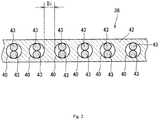
FIG. 2] FIG. 2 is an enlarged cross-sectional view of a structure of a belt shown inFIG. 1 . - [
FIG. 3] FIG. 3 is a schematic diagram illustrating the structure of the belt shown inFIG. 1 . - The following will describe in detail the present invention based on preferred embodiments with reference where appropriate to the accompanying drawings.
-
FIG. 1 shows apneumatic tire 2. InFIG. 1 , the up-down direction represents the radial direction of thetire 2, the right-left direction represents the axial direction of thetire 2, and the direction perpendicular to the surface of the drawing sheet represents the circumferential direction of thetire 2. InFIG. 1 , an alternate long and short dash line CL represents the equator plane of thetire 2. Thetire 2 has a shape which is symmetric about the equator plane except for a tread pattern. - The
tire 2 includes atread 4, a pair ofsidewalls 6, a pair ofclinches 8, a pair ofbeads 10, acarcass 12, abelt 14, aband 16, aninner liner 18, andchafers 19. Thetire 2 is of a tubeless type. Thetire 2 is mounted to a passenger car. - The
tread 4 has a shape that projects outward in the radial direction. Thetread 4 forms atread surface 20 that comes into contact with a road surface. Thetread surface 20 hasgrooves 22 formed therein. Thegrooves 22 form the tread pattern. Thetread 4 has abase layer 24 and acap layer 26. Thecap layer 26 is disposed radially outward of thebase layer 24. Thecap layer 26 is layered over thebase layer 24. Thebase layer 24 is formed from crosslinked rubber excellent in adhesiveness. A typical base rubber of thebase layer 24 is natural rubber. Thecap layer 26 is formed from crosslinked rubber excellent in wear resistance, heat resistance, and grip performance. - The
sidewalls 6 extend almost inward from the ends, respectively, of thetread 4 in the radial direction. Thesidewalls 6 are formed from crosslinked rubber excellent in cut resistance and weather resistance. Thesidewalls 6 prevent damage to thecarcass 12. - The
clinches 8 are disposed almost inward of thesidewalls 6, respectively, in the radial direction. Theclinches 8 are disposed outward of thebeads 10 and thecarcass 12 in the axial direction. Theclinches 8 are formed from crosslinked rubber excellent in wear resistance. Theclinch 8 comes into contact with a flange of a rim. - The
beads 10 are disposed inward of theclinches 8, respectively, in the axial direction. Eachbead 10 includes acore 28 and an apex 30 that extends outward from the core 28 in the radial direction. Thecore 28 is ring-shaped, and includes a wound non-stretchable wire. A typical material of the wire is steel. The apex 30 is tapered outward in the radial direction. The apex 30 is formed from highly hard crosslinked rubber. - The
carcass 12 includes acarcass ply 32. The carcass ply 32 is extended on and between thebeads 10 on both sides, along thetread 4 and thesidewalls 6. The carcass ply 32 is turned up around thecores 28 from the inner side toward the outer side in the axial direction. By the carcass ply 32 being turned up, the carcass ply 32 has amain portion 34 and turned-upportions 35. - The carcass ply 32 includes multiple cords aligned with each other and a topping rubber, which is not shown. An absolute value of an angle of each cord relative to the equator plane is from 75° to 90°. In other words, the
carcass 12 has a radial structure. The cords are formed from an organic fiber. Preferable examples of the organic fiber include polyester fibers, nylon fibers, rayon fibers, polyethylene naphthalate fibers, and aramid fibers. Thecarcass 12 may include two or more plies. - The
belt 14 is disposed radially inward of thetread 4. Thebelt 14 is layered over thecarcass 12. Thebelt 14 reinforces thecarcass 12. Thebelt 14 includes aninner layer 36 and anouter layer 38. As shown inFIG. 1 , in the present embodiment, the width of theinner layer 36 is greater than the width of theouter layer 38. Thebelt 14 may include three or more layers. - The
band 16 is disposed radially inward of thetread 4. Theband 16 is disposed radially outward of thebelt 14. Theband 16 is layered over thebelt 14. Theband 16 includes a cord and a topping rubber. The cord is helically wound. Theband 16 has a so-called jointless structure. The cord extends substantially in the circumferential direction. An angle of the cord relative to the circumferential direction is less than or equal to 5°, and more preferably less than or equal to 2°. Theband 16 can contribute to stiffness of thetire 2. Theband 16 can reduce influence of a centrifugal force that acts during running. Thetire 2 is excellent in high speed stability. A material of the cord is steel. An organic fiber may be used for the cord. Preferable examples of the organic fiber include nylon fibers, polyester fibers, rayon fibers, polyethylene naphthalate fibers, and aramid fibers. - The
inner liner 18 is disposed inward of thecarcass 12. Theinner liner 18 is joined to the inner surface of thecarcass 12. Theinner liner 18 is formed from crosslinked rubber. For theinner liner 18, rubber excellent in airtightness is used. Atypical base rubber of theinner liner 18 is isobutylene-isoprene-rubber or halogenated isobutylene-isoprene-rubber. Theinner liner 18 maintains internal pressure of thetire 2. - The
chafers 19 are disposed near thebeads 10, respectively. When thetire 2 is mounted on a rim, thechafers 19 come into contact with the rim. By the contact, portions near thebeads 10 are protected. In the present embodiment, thechafers 19 are formed from a fabric and rubber impregnated into the fabric. Thechafers 19 may be integrated with theclinches 8. In this case, the material of thechafers 19 is the same as the material of theclinches 8. -
FIG. 2 is an enlarged cross-sectional view of a part of theinner layer 36 of thebelt 14. Theinner layer 36 includesmultiple cords 40 aligned with each other, and a toppingrubber 42.FIG. 2 shows a cross-section perpendicular to a direction in which thecords 40 extend. As shown inFIG. 2 , the toppingrubber 42 covers thecords 40. A material of thecords 40 is steel. In the present embodiment, eachcord 40 is formed by twoelement wires 43 formed from steel being twisted together. Theouter layer 38 has the same structure as theinner layer 36, which is not shown. That is, theouter layer 38 includes multiple cords aligned with each other, and a topping rubber. A material of the cords is steel. Each cord is formed by two element wires formed from steel being twisted together. In the present embodiment, thecords 40 of theinner layer 36 and the cords of theouter layer 38 have the same structure. Thecord 40 of theinner layer 36 and the cord of theouter layer 38 may have different structures. In the present embodiment, a composition of the toppingrubber 42 of theinner layer 36 is the same as a composition of the topping rubber of theouter layer 38. A composition of the toppingrubber 42 of theinner layer 36 and a composition of the topping rubber of theouter layer 38 may be different from each other. - When CV represents a volume of the total of all the
cords 40 of theinner layer 36 and all the cords of theouter layer 38, and BV represents the total volume of thebelt 14 that includes theinner layer 36 and theouter layer 38, a percentage (CV/BV) of the volume CV to the volume BV is greater than or equal to 11% and not greater than 14% in thetire 2. The thickness of each of thecords 40 of theinner layer 36 and the cords of theouter layer 38, and the intervals between thecords 40 of theinner layer 36 and the intervals between the cords of theouter layer 38 are determined such that the percentage (CV/BV) is greater than or equal to 11% and not greater than 14%. The size of the toppingrubber 42 of theinner layer 36 and the size of the topping rubber of the outer layer are determined such that the percentage (CV/BV) is greater than or equal to 11% and not greater than 14%. - In the present embodiment, the
inner layer 36 and theouter layer 38 have the same structure. That is, when CVi represents the volume of the total of all thecords 40 of theinner layer 36, and BVi represents the total volume of theinner layer 36, a percentage (CVi/BVi) of the volume CVi to the volume BVi is greater than or equal to 11% and not greater than 14%. When CVo represents the volume of the total of all the cords of theouter layer 38, and BVo represents the total volume of theouter layer 38, a percentage (CVo/BVo) of the volume CVo to the volume BVo is greater than or equal to 11% and not greater than 14%. -
FIG. 3 is a schematic diagram illustrating the structure of thebelt 14. InFIG. 3 , the up-down direction represents the circumferential direction of thetire 2, the right-left direction represents the axial direction of thetire 2, and the direction perpendicular to the surface of the drawing sheet represents the radial direction of thetire 2. As shown inFIG. 3 , thecords 40 of theinner layer 36 and thecords 44 of theouter layer 38 are tilted relative to the circumferential direction. A direction in which thecords 40 of theinner layer 36 are tilted relative to the circumferential direction is opposite to a direction in which thecords 44 of theouter layer 38 are tilted relative to the circumferential direction. - As shown in
FIG. 3 , in the present embodiment, an angle at which eachcord 40 of theinner layer 36 is tilted is changed at a pair of imaginary straight lines Li that extend as boundaries in the circumferential direction. A portion between the paired straight lines Li is a center portion Ci of theinner layer 36. Portions outward of the paired straight lines Li in the axial direction are shoulder portions Si of theinner layer 36. Reference character αi represents an angle at which eachcord 40 of theinner layer 36 is tiled relative to the circumferential direction in the center portion Ci of theinner layer 36. Reference character βi represents an angle at which eachcord 40 of theinner layer 36 is tilted relative to the circumferential direction in each shoulder portion Si of theinner layer 36. In the present embodiment, the absolute value of the tilt angle βi is greater than the absolute value of the tilt angle αi. Thecords 40 of theinner layer 36 are tilted relative to the circumferential direction in the shoulder portions Si of theinner layer 36 more greatly than in the center portion Ci thereof. - In
FIG. 3 , a double-headed arrow Wi represents a distance from the equator plane to the straight line Li in the axial direction. InFIG. 1 , Wt represents a distance from the equator plane to a tread end in the axial direction. A ratio (Wi/Wt) of the distance Wi to the distance Wt is greater than or equal to 0.5 and not greater than 0.8. - As shown in
FIG. 3 , in the present embodiment, an angle at which eachcord 44 of theouter layer 38 is tilted is changed at a pair of the imaginary straight lines Lo that extend as boundaries in the circumferential direction. A portion between the paired straight lines Lo is a center portion Co of theouter layer 38. Portions outward of the paired straight lines Lo in the axial direction are shoulder portions So of theouter layer 38. Reference character αo represents an angle at which eachcord 44 of theouter layer 38 is tilted relative to the circumferential direction in the center portion Co of theouter layer 38. Reference character βo represents an angle at which eachcord 44 of theouter layer 38 is tilted relative to the circumferential direction in each shoulder portion So of theouter layer 38. In the present embodiment, the absolute value of the tilt angle βo is greater than the absolute value of the tilt angle αo. Thecords 44 of theouter layer 38 are tilted relative to the circumferential direction in the shoulder portions So of theouter layer 38 more greatly than in the center portion Co thereof. - In
FIG. 3 , a double-headed arrow Wo represents a distance from the equator plane to the straight line Lo in the axial direction. A ratio (Wo/Wt) of the distance Wo to the distance Wt is greater than or equal to 0.5 and not greater than 0.8. - In the present embodiment, a difference between the absolute value of the angle αi and the absolute value of the angle αo in the
outer layer 38 is less than or equal to 2°. The absolute values of the angles αi and αo are each from 10° to 35°. - Hereinafter, the action and effect of the present invention will be described.
- Steering stability is required to be further improved for a tire having a high load index. Durability is also required to be improved in a tire having a high load index. In particular, in a tire having a load index which is higher than or equal to 85, steering stability and durability are strongly required to be improved.
- The inventors have studied the structure of a belt in detail. As a result, it has been found that a proportion between the volume of a belt and the volume of cords included in the belt exerts a great influence on steering stability and durability. It has been found that, when the proportion is appropriately set, steering stability and durability are advantageously improved also in the
tire 2 having a high load index. - In the
tire 2, the percentage (CV/BV) of the volume CV of thecords belt 14 is greater than or equal to 11% and not greater than 14%. When the percentage (CV/BV) is greater than or equal to 11%, thebelt 14 contributes to steering stability. Further, thebelt 14 effectively reinforces thecarcass 12. Thetire 2 having thebelt 14 is excellent in durability. When the percentage (CV/BV) is not greater than 14%, BEL due to rubber around thecords tire 2 is excellent in durability. In thetire 2, steering stability and durability are advantageously improved. - In the
tire 2, when the percentage (CV/BV) is not greater than 14%, the stiffness of thetread 4 is appropriately maintained. This effectively contributes to ride comfort. Thetire 2 allows ride comfort to be advantageously improved. Further, when the percentage (CV/BV) is not greater than 14% in thebelt 14, thebelt 14 is lightweight. Thetire 2 having thebelt 14 is lightweight. Thebelt 14 contributes to reduction of rolling resistance of thetire 2. - From the viewpoint of steering stability and durability being advantageously improved, the percentage (CV/BV) is more preferably greater than or equal to 12%. From the viewpoint that durability and ride comfort are advantageously improved and weight is reduced, the percentage (CV/BV) is more preferably not greater than 13.5%.
- As described above, the tilt angle βi relative to the circumferential direction in the shoulder portions is preferably greater than the tilt angle αi relative to the circumferential direction in the center portion in the
cord 40 of theinner layer 36. When the tilt angle αi of thecord 40 in the center portion is small in thebelt 14, thebelt 14 effectively contributes to stiffness of thetread 4 in the circumferential direction. Thetire 2 is excellent in steering stability and durability during high speed running. When the tilt angle βi of thecord 40 in the shoulder portions is great in thebelt 14, thebelt 14 effectively contributes to stiffness of thetread 4 in the lateral direction. Thetire 2 is excellent in steering stability and durability during cornering. - A difference between the tilt angle αi and the tilt angle βi is preferably greater than or equal to 1.5°. When the difference is greater than or equal to 1.5°, the
belt 14 effectively contributes to stiffness in the circumferential direction and the lateral direction. Thetire 2 is excellent in steering stability and durability during the straight running and cornering. The difference between the tilt angle αi and the tilt angle βi is preferably not greater than 2.5°. When the difference between the tilt angle αi and the tilt angle βi is not greater than 2.5°, reduction of ride comfort due to difference in stiffness between the center portion and the shoulder portions in thetread 4 can be inhibited. Thetire 2 is excellent in ride comfort. - As described above, the tilt angle βo relative to the circumferential direction in the shoulder portions is preferably greater than the tilt angle αo relative to the circumferential direction in the center portion in the
cord 44 of theouter layer 38. When the tilt angle αo of thecord 44 in the center portion is small in thebelt 14, thebelt 14 effectively contributes to stiffness of thetread 4 in the circumferential direction. Thetire 2 is excellent in steering stability and durability during high speed running. When the tilt angle βo of thecord 44 in the shoulder portions is great in thebelt 14, thebelt 14 effectively contributes to stiffness of thetread 4 in the lateral direction. Thetire 2 is excellent in steering stability and durability during cornering. - A difference between the tilt angle αo and the tilt angle βo is preferably greater than or equal to 1.5°. When the difference is greater than or equal to 1.5°, the
belt 14 effectively contributes to stiffness in the circumferential direction and the lateral direction. Thetire 2 is excellent in steering stability and durability during straight running and cornering. The difference between the tilt angle αo and the tilt angle βo is preferably not greater than 2.5°. When the difference between the tilt angle αo and the tilt angle βo is not greater than 2.5°, reduction of ride comfort due to difference in stiffness between the center portion and the shoulder portions in thetread 4 can be inhibited. Thetire 2 is excellent in ride comfort. - As described above, in the
belt 14 of thetire 2, the percentage (CV/BV) is greater than or equal to 11% and not greater than 14%. In order to allow thebelt 14 to satisfy this condition, as described above, the tilt angle of thecord 40 in the shoulder portions Si of theinner layer 36 is made greater than the tilt angle of the cord in the center portion Ci thereof, and the tilt angle of thecord 44 in the shoulder portions So of theouter layer 38 is made greater than the tilt angle of thecord 44 in the center portion Co thereof. Thus, thebelt 14 particularly effectively contributes to steering stability and durability. By combination thereof, thetire 2 excellent in steering stability and durability can be obtained. - As described above, in the
inner layer 36 of thebelt 14, a difference between the tilt angle αi and the tilt angle βi is greater than or equal to 1.5° and not greater than 2.5°. In theinner layer 36, the difference of the tilt angle of thecord 40 between the center portion Ci and the shoulder portions Si is appropriately set. In theouter layer 38 of thebelt 14, a difference between the tilt angle αo and the tilt angle βo is greater than or equal to 1.5° and not greater than 2.5°. In theouter layer 38, the difference of the tilt angle of thecord 44 between the center portion Co and the shoulder portions So is appropriately set. Thebelt 14 can be obtained by the circumferential length of a drum in forming and a shape of a cavity surface of a mold in vulcanization being adjusted. In manufacturing of thetire 2, for each of theinner layer 36 and theouter layer 38, no specific process step is required for changing the tilt angle of thecord tire 2, productivity is maintained good. - In
FIG. 2 , a double-headed arrow Di represents the width of a gap between thecords 40 adjacent to each other in theinner layer 36. The width Di is preferably greater than or equal to 0.4 mm. When the width Di is greater than or equal to 0.4 mm in theinner layer 36, even if thebelt 14 is deformed due to load, thecords 40 adjacent to each other are prevented from contacting with each other. In theinner layer 36, damage to thecords 40 due to contact between thecords 40, is prevented. Thetire 2 including theinner layer 36 is excellent in durability. In this viewpoint, the width Di is more preferably greater than or equal to 0.45 mm. - A double-headed arrow Do, which is not shown, represents a width of a gap between the
cords 44 adjacent to each other in theouter layer 38. The width Do is preferably greater than or equal to 0.4 mm. When the width Do is greater than or equal to 0.4 mm in theouter layer 38, even if thebelt 14 is deformed due to load, thecords 44 adjacent to each other are prevented from contacting with each other. In theouter layer 38, damage to thecords 44 due to contact between thecords 44, is prevented. Thetire 2 including theouter layer 38 is excellent in durability. In this viewpoint, the width Do is more preferably greater than or equal to 0.45 mm. - A double-headed arrow Dio, which is not shown, represents a width of a gap between the
cord 40 of theinner layer 36 and thecord 44, adjacent thereto, of theouter layer 38. The width Dio is preferably greater than or equal to 0.4 mm. When the width Dio is greater than or equal to 0.4 mm in thebelt 14, even if thebelt 14 is deformed due to load, thecord 40 of theinner layer 36 and thecord 44, adjacent thereto, of theouter layer 38 are prevented from contacting with each other. In thebelt 14, damage to thecords tire 2 including thebelt 14 is excellent in durability. In this viewpoint, the width Dio is more preferably greater than or equal to 0.45 mm. - The characteristics of a topping rubber of a belt exert an influence on performance of a tire. A hard topping rubber contributes to stiffness of the belt. A tire including a hard topping rubber is excellent in steering stability. However, a hard topping rubber causes reduction of impact absorption of the tire. The tire is poor in ride comfort. A tire including a soft topping rubber is excellent in ride comfort, but is poor in steering stability. The inventors have found that, when, in a tire in which the percentage (CV/BV) of the volume CV to the volume BV is greater than or equal to 11% and not greater than 14%, a complex elastic modulus of the topping rubber is appropriately set, steering stability and ride comfort can be further improved.
- A complex elastic modulus E*i of the topping
rubber 42 of theinner layer 36 is preferably higher than or equal to 8 MPa. When the complex elastic modulus E*i is higher than or equal to 8 MPa, the toppingrubber 42 effectively contributes to stiffness of thebelt 14. The tire is excellent in steering stability. In this viewpoint, the complex elastic modulus E*i is more preferably higher than or equal to 9 MPa. The complex elastic modulus E*i is preferably not higher than 12 MPa. When the complex elastic modulus E*i is not higher than 12 MPa, the stiffness of thebelt 14 is appropriately set. The tire is excellent in ride comfort. In this viewpoint, the complex elastic modulus E*i is more preferably not higher than 11 MPa. - A complex elastic modulus E*o of the topping rubber of the
outer layer 38 is preferably higher than or equal to 8 MPa. When the complex elastic modulus E*o is higher than or equal to 8 MPa, the topping rubber effectively contributes to stiffness of thebelt 14. The tire is excellent in steering stability. In this viewpoint, the complex elastic modulus E*o is more preferably higher than or equal to 9 MPa. The complex elastic modulus E*o is preferably not higher than 12 MPa. When the complex elastic modulus E*o is not higher than 12 MPa, the stiffness of thebelt 14 is appropriately set. The tire is excellent in ride comfort. In this view point, the complex elastic modulus E*o is more preferably not higher than 11 MPa. - In the present invention, the complex elastic moduli E*i and E*o are measured in compliance with the standard of "JIS K 6394", by using a viscoelasticity spectrometer (trade name "VESF-3" manufactured by Iwamoto Seisakusho), under the following measurement conditions.
- Initial strain: 10%
- Amplitude: ±2.0%
- Frequency: 10 Hz
- Deformation mode: tension
- Measurement temperature: 70°C
- In the present invention, the dimensions and angles of the components of the
tire 2 are measured in a state where thetire 2 is mounted on a normal rim, and inflated with air to a normal internal pressure. During the measurement, no load is applied to thetire 2. In the description herein, the normal rim represents a rim that is specified according to the standard with which thetire 2 complies. The "standard rim" in the JATMA standard, the "Design Rim" in the TRA standard, and the "Measuring Rim" in the ETRTO standard are included in the normal rim. In the description herein, the normal internal pressure represents an internal pressure that is specified according to the standard with which thetire 2 complies. The "maximum air pressure" in the JATMA standard, the "maximum value" recited in "TIRE LOAD LIMITS AT VARIOUS COLD INFLATION PRESSURES" in the TRA standard, and the "INFLATION PRESSURE" in the ETRTO standard, are included in the normal internal pressure. In the case of thetire 2 for a passenger car, in a state where the internal pressure is 180 kPa, the dimensions and angles are measured. - Hereinafter, effects of the present invention will become apparent according to examples. However, the present invention should not be restrictively construed based on the description of examples.
- A tire, of example 1, having the structure shown in
FIG. 1 was obtained. The size of the tire was "205/60R16 96V L". The specifications of a belt of the tire are indicated in Table 1. - Tires of comparative examples 1 to 3 and examples 2 to 4 were each obtained in the same manner as in example 1 except that the width Di and the width Do were different and the percentage (CV/BV) was as indicated in Tables 1 to 2.
- A tire of example 5 was obtained in the same manner as in example 1 except that the width Dio was different and the percentage (CV/BV) was as indicated in Table 2.
- Tires of examples 6 to 9 were each obtained in the same manner as in example 1 except that the angles αi and αo were as indicated in Table 3.
- Tires of examples 10 to 13 were each obtained in the same manner as in example 1 except that the complex elastic modulus E*i and the complex elastic modulus E*o were as indicated in Table 4.
- Each tire was mounted on a normal rim (size: 6.5J), and inflated with air to an internal pressure of 250 kPa. The tires were mounted to rear wheels of a vehicle. A driver was caused to drive this vehicle in a test course, and to evaluate steering stability and ride comfort. The results are indicated below as grades in Tables 1 to 4 with 10 being the best grade. The greater the value is, the better the evaluation is.
- Each tire was mounted on a normal rim (size: 6.5J), and inflated with air to an internal pressure of 290 kPa. The tire was mounted to a drum type tire testing machine, and a vertical load of 10.27 kN was applied to the tire. Running with the tire on a drum having a radius of 1.7 m at a speed of 80 km/h was performed. A running distance until damage to the tire was confirmed, was measured. The results are indicated below as indexes in Tables 1 to 4. The greater the value is, the better the evaluation is.
-
Table 1 Evaluation results Comparative example 1 Comparative example 2 Example 2 Example 1 Percentage (CV/BV) [%] 9.6 10.7 11.3 12.3 Inner layer Width Di [mm] 0.80 0.66 0.61 0.50 Angle αi [°] 28 28 28 28 Angle βi [°] 26 26 26 26 E*i [MPa] 10 10 10 10 Outer layer Width Do [mm] 0.80 0.66 0.61 0.50 Angle αo [°] 28 28 28 28 Angle βo [°] 26 26 26 26 E*o [MPa] 10 10 10 10 Width Dio [mm] 0.43 0.43 0.43 0.43 Steering stability 5 5.5 6 7 Ride comfort 7 7 7 7 Durability 100 102 115 120 -
Table 2 Evaluation results Example 3 Example 4 Comparative example 3 Example 5 Percentage (CV/BV) [%] 13.4 14.0 15.5 14.0 Inner layer Width Di [mm] 0.41 0.37 0.27 0.50 Angle αi [°] 28 28 28 28 Angle βi [°] 26 26 26 26 E*i [MPa] 10 10 10 10 Outer layer Width Do [mm] 0.41 0.37 0.27 0.50 Angle αo [°] 28 28 28 28 Angle βo [°] 26 26 26 26 E*o [MPa] 10 10 10 10 Width Dio [mm] 0.43 0.43 0.43 0.31 Steering stability 7 7 7 7 Ride comfort 6.5 6 5 6.5 Durability 110 100 95 100 -
Table 3 Evaluation results Example 6 Example 7 Example 8 Example 9 Percentage (CV/BV) [%] 12.3 12.3 12.3 12.3 Inner layer Width Di [mm] 0.50 0.50 0.50 0.50 Angle αi [°] 26 27.5 28.8 30 Angle βi [°] 26 26 26 26 E*i [MPa] 10 10 10 10 Outer layer Width Do [mm] 0.50 0.50 0.50 0.50 Angle αo [°] 26 27.5 28.8 30 Angle βo [°] 26 26 26 26 E*o [MPa] 10 10 10 10 Width Dio [mm] 0.43 0.43 0.43 0.43 Steering stability 6.5 7 7 7 Ride comfort 7 7 6.5 6 Durability 110 120 120 120 -
Table 4 Evaluation results Example 10 Example 11 Example 12 Example 13 Percentage (CV/BV) [%] 12.3 12.3 12.3 12.3 Inner layer Width Di [mm] 0.50 0.50 0.50 0.50 Angle αi [°] 28 28 28 28 Angle βi [°] 26 26 26 26 E*i [MPa] 7.5 8 12 12.5 Outer layer Width Do [mm] 0.50 0.50 0.50 0.50 Angle αo [°] 28 28 28 28 Angle βo [°] 26 26 26 26 E*o [MPa] 7.5 8 12 12.5 Width Dio [mm] 0.43 0.43 0.43 0.43 Steering stability 6 6.5 7 7 Ride comfort 7 7 6.5 6 Durability 120 120 120 120 - As indicated in Tables 1 to 4, the tires of examples are more excellent in the values than the tires of comparative examples. The evaluation result clearly indicates that the present invention is superior.
- The tire according to the present invention can be mounted to various vehicles.
-
- 2···tire
- 4···tread
- 6···sidewall
- 8···clinch
- 10···bead
- 12···carcass
- 14···belt
- 16···band
- 18···inner liner
- 19···chafer
- 20···tread surface
- 22···groove
- 24···base layer
- 26···cap layer
- 28···core
- 30···apex
- 32···carcass ply
- 34···main portion
- 35···turned-up portion
- 36···inner layer
- 38···outer layer
- 40···cord of inner layer
- 42···topping rubber
- 43···element wire
- 44···cord of outer layer
Claims (4)
- A pneumatic tire (2) comprising:a tread (4) having an outer surface forming a tread surface (20); anda belt (14) disposed inward of the tread (4) in a radial direction,wherein the belt (14) includes an inner layer (36), and an outer layer (38) layered outward of the inner layer (36) in the radial direction,wherein the inner layer (36) and the outer layer (38) each include multiple cords (40, 44) which are formed from steel and aligned with each other,wherein a percentage (CV/BV) of a volume (CV) of the cords (40, 44) to a total volume (BV) of the belt (14) is greater than or equal to 11% and not greater than 14%,wherein the cords (40) of the inner layer (36) and the cords (44) of the outer layer (38) are tilted relative to a circumferential direction, andwherein a direction in which the cords (40) of the inner layer (36) are tilted relative to the circumferential direction and a direction in which the cords (44) of the outer layer (38) are tilted relative to the circumferential direction are opposite to each other,characterized in thatin the inner layer (36), an absolute value of a tilt angle αi of each cord (40) relative to the circumferential direction in a center portion (Ci) of the inner layer (36) is less than an absolute value of a tilt angle βi of each cord (40) relative to the circumferential direction in shoulder portions (Si) of the inner layer (36),a difference between the angle αi and the angle βi is greater than or equal to 1.5° and not greater than 2.5°,in the outer layer (38), an absolute value of a tilt angle αo of each cord (44) relative to the circumferential direction in a center portion (Co) of the outer layer (38) is less than an absolute value of a tilt angle βo of each cord (44) relative to the circumferential direction in shoulder portions (So) of the outer layer (38),a difference between the angle αo and the angle βo is greater than or equal to 1.5° and not greater than 2.5°,absolute values of the angles αi and αo are each from 10 degrees to 35 degrees, andthe tire (2) further comprising a band (16) including a cord and a topping rubber, wherein the cord extends at an angle of less than or equal 5 degrees with respect to the tire circumferential direction.
- The tire (2) according to claim 1, wherein,in the inner layer (36), a width of a gap (Di) between the cords (40) adjacent to each other is greater than or equal to 0.4 mm, andin the outer layer (38), a width of a gap (Do) between the cords (44) adjacent to each other is greater than or equal to 0.4 mm.
- The tire (2) according to any one of claims 1 or 2, wherein a width of a gap (Dio) between the cord (40) of the inner layer (36) and the cord (44) of the outer layer (38) is greater than or equal to 0.4 mm.
- The tire (2) according to any one of claims 1 to 3, whereineach of the inner layer (36) and the outer layer (38) further includes topping rubber, anda complex elastic modulus E*i of the topping rubber (42) of the inner layer (36) at 70° is higher than or equal to 8 MPa and not higher than 12 MPa, anda complex elastic modulus E*o of the topping rubber of the outer layer (38) at 70° is higher than or equal to 8 MPa and not higher than 12 MPa.
Applications Claiming Priority (2)
| Application Number | Priority Date | Filing Date | Title |
|---|---|---|---|
| JP2016075512 | 2016-04-05 | ||
| JP2016144470A JP6790547B2 (en) | 2016-04-05 | 2016-07-22 | Pneumatic tires |
Publications (2)
| Publication Number | Publication Date |
|---|---|
| EP3228476A1 EP3228476A1 (en) | 2017-10-11 |
| EP3228476B1 true EP3228476B1 (en) | 2020-06-03 |
Family
ID=58672300
Family Applications (1)
| Application Number | Title | Priority Date | Filing Date |
|---|---|---|---|
| EP17164835.5A Active EP3228476B1 (en) | 2016-04-05 | 2017-04-04 | Pneumatic tire |
Country Status (1)
| Country | Link |
|---|---|
| EP (1) | EP3228476B1 (en) |
Family Cites Families (8)
| Publication number | Priority date | Publication date | Assignee | Title |
|---|---|---|---|---|
| JPS59124409A (en) * | 1982-12-30 | 1984-07-18 | Yokohama Rubber Co Ltd:The | Pneumatic radial tire |
| JPH07112762B2 (en) * | 1987-10-13 | 1995-12-06 | 住友ゴム工業株式会社 | Pneumatic radial tires |
| JP2742310B2 (en) * | 1989-11-30 | 1998-04-22 | 住友ゴム工業 株式会社 | Radial tires for passenger cars |
| AT402383B (en) * | 1995-04-21 | 1997-04-25 | Semperit Ag | VEHICLE AIR TIRES IN RADIAL DESIGN |
| JP2003226112A (en) * | 2002-02-06 | 2003-08-12 | Yokohama Rubber Co Ltd:The | Pneumatic radial tire for heavy load |
| DE102004029987A1 (en) * | 2004-06-21 | 2006-01-05 | Continental Aktiengesellschaft | Pneumatic vehicle tire with radial construction has breaker layer with cords whose alignment to the tire circumference changes across the breaker layer breadth |
| JP4785428B2 (en) | 2005-06-07 | 2011-10-05 | 株式会社ブリヂストン | Pneumatic tire |
| JP6348713B2 (en) | 2014-01-09 | 2018-06-27 | 住友ゴム工業株式会社 | Pneumatic tire |
-
2017
- 2017-04-04 EP EP17164835.5A patent/EP3228476B1/en active Active
Non-Patent Citations (1)
| Title |
|---|
| None * |
Also Published As
| Publication number | Publication date |
|---|---|
| EP3228476A1 (en) | 2017-10-11 |
Similar Documents
| Publication | Publication Date | Title |
|---|---|---|
| EP3127717B1 (en) | Pneumatic tire | |
| EP3315327B1 (en) | Pneumatic tire | |
| EP2676808B1 (en) | Pneumatic tire | |
| EP2818332B1 (en) | Pneumatic tire | |
| EP3587144B1 (en) | Pneumatic tire | |
| US9272582B2 (en) | Pneumatic tire | |
| EP3281805B1 (en) | Pneumatic tire | |
| EP3202595B1 (en) | Pneumatic tire | |
| EP3202594B1 (en) | Pneumatic tire | |
| EP3189987B1 (en) | Pneumatic tire | |
| EP3530485B2 (en) | Pneumatic tire | |
| EP3599108A1 (en) | Pneumatic tire | |
| EP3594025B1 (en) | Pneumatic tire | |
| EP3321107B1 (en) | Pneumatic tire | |
| EP3189979B1 (en) | Pneumatic tire | |
| EP3178666A1 (en) | Tire for two-wheeled vehicles | |
| EP3235664B1 (en) | Pneumatic tire | |
| EP4180241A1 (en) | Heavy duty pneumatic tire | |
| EP2998128B1 (en) | Pneumatic tire | |
| EP3202599B1 (en) | Pneumatic tire | |
| EP3366495B1 (en) | Tire for two-wheeled automotive vehicle | |
| JP6790547B2 (en) | Pneumatic tires | |
| EP3366492A1 (en) | Pneumatic tire for two-wheeled automotive vehicle | |
| EP3228476B1 (en) | Pneumatic tire | |
| EP2865547B1 (en) | Pneumatic tire |
Legal Events
| Date | Code | Title | Description |
|---|---|---|---|
| PUAI | Public reference made under article 153(3) epc to a published international application that has entered the european phase |
Free format text: ORIGINAL CODE: 0009012 |
|
| STAA | Information on the status of an ep patent application or granted ep patent |
Free format text: STATUS: THE APPLICATION HAS BEEN PUBLISHED |
|
| AK | Designated contracting states |
Kind code of ref document: A1 Designated state(s): AL AT BE BG CH CY CZ DE DK EE ES FI FR GB GR HR HU IE IS IT LI LT LU LV MC MK MT NL NO PL PT RO RS SE SI SK SM TR |
|
| AX | Request for extension of the european patent |
Extension state: BA ME |
|
| STAA | Information on the status of an ep patent application or granted ep patent |
Free format text: STATUS: REQUEST FOR EXAMINATION WAS MADE |
|
| 17P | Request for examination filed |
Effective date: 20171219 |
|
| RBV | Designated contracting states (corrected) |
Designated state(s): AL AT BE BG CH CY CZ DE DK EE ES FI FR GB GR HR HU IE IS IT LI LT LU LV MC MK MT NL NO PL PT RO RS SE SI SK SM TR |
|
| STAA | Information on the status of an ep patent application or granted ep patent |
Free format text: STATUS: EXAMINATION IS IN PROGRESS |
|
| 17Q | First examination report despatched |
Effective date: 20190830 |
|
| GRAP | Despatch of communication of intention to grant a patent |
Free format text: ORIGINAL CODE: EPIDOSNIGR1 |
|
| STAA | Information on the status of an ep patent application or granted ep patent |
Free format text: STATUS: GRANT OF PATENT IS INTENDED |
|
| INTG | Intention to grant announced |
Effective date: 20200319 |
|
| RIN1 | Information on inventor provided before grant (corrected) |
Inventor name: ITO, HIROSHI Inventor name: SUENO, JUNYA |
|
| GRAS | Grant fee paid |
Free format text: ORIGINAL CODE: EPIDOSNIGR3 |
|
| GRAA | (expected) grant |
Free format text: ORIGINAL CODE: 0009210 |
|
| STAA | Information on the status of an ep patent application or granted ep patent |
Free format text: STATUS: THE PATENT HAS BEEN GRANTED |
|
| AK | Designated contracting states |
Kind code of ref document: B1 Designated state(s): AL AT BE BG CH CY CZ DE DK EE ES FI FR GB GR HR HU IE IS IT LI LT LU LV MC MK MT NL NO PL PT RO RS SE SI SK SM TR |
|
| REG | Reference to a national code |
Ref country code: GB Ref legal event code: FG4D |
|
| REG | Reference to a national code |
Ref country code: CH Ref legal event code: EP Ref country code: AT Ref legal event code: REF Ref document number: 1276649 Country of ref document: AT Kind code of ref document: T Effective date: 20200615 |
|
| REG | Reference to a national code |
Ref country code: DE Ref legal event code: R096 Ref document number: 602017017522 Country of ref document: DE |
|
| REG | Reference to a national code |
Ref country code: LT Ref legal event code: MG4D |
|
| PG25 | Lapsed in a contracting state [announced via postgrant information from national office to epo] |
Ref country code: FI Free format text: LAPSE BECAUSE OF FAILURE TO SUBMIT A TRANSLATION OF THE DESCRIPTION OR TO PAY THE FEE WITHIN THE PRESCRIBED TIME-LIMIT Effective date: 20200603 Ref country code: SE Free format text: LAPSE BECAUSE OF FAILURE TO SUBMIT A TRANSLATION OF THE DESCRIPTION OR TO PAY THE FEE WITHIN THE PRESCRIBED TIME-LIMIT Effective date: 20200603 Ref country code: LT Free format text: LAPSE BECAUSE OF FAILURE TO SUBMIT A TRANSLATION OF THE DESCRIPTION OR TO PAY THE FEE WITHIN THE PRESCRIBED TIME-LIMIT Effective date: 20200603 Ref country code: NO Free format text: LAPSE BECAUSE OF FAILURE TO SUBMIT A TRANSLATION OF THE DESCRIPTION OR TO PAY THE FEE WITHIN THE PRESCRIBED TIME-LIMIT Effective date: 20200903 Ref country code: GR Free format text: LAPSE BECAUSE OF FAILURE TO SUBMIT A TRANSLATION OF THE DESCRIPTION OR TO PAY THE FEE WITHIN THE PRESCRIBED TIME-LIMIT Effective date: 20200904 |
|
| REG | Reference to a national code |
Ref country code: NL Ref legal event code: MP Effective date: 20200603 |
|
| PG25 | Lapsed in a contracting state [announced via postgrant information from national office to epo] |
Ref country code: BG Free format text: LAPSE BECAUSE OF FAILURE TO SUBMIT A TRANSLATION OF THE DESCRIPTION OR TO PAY THE FEE WITHIN THE PRESCRIBED TIME-LIMIT Effective date: 20200903 Ref country code: RS Free format text: LAPSE BECAUSE OF FAILURE TO SUBMIT A TRANSLATION OF THE DESCRIPTION OR TO PAY THE FEE WITHIN THE PRESCRIBED TIME-LIMIT Effective date: 20200603 Ref country code: HR Free format text: LAPSE BECAUSE OF FAILURE TO SUBMIT A TRANSLATION OF THE DESCRIPTION OR TO PAY THE FEE WITHIN THE PRESCRIBED TIME-LIMIT Effective date: 20200603 Ref country code: LV Free format text: LAPSE BECAUSE OF FAILURE TO SUBMIT A TRANSLATION OF THE DESCRIPTION OR TO PAY THE FEE WITHIN THE PRESCRIBED TIME-LIMIT Effective date: 20200603 |
|
| REG | Reference to a national code |
Ref country code: AT Ref legal event code: MK05 Ref document number: 1276649 Country of ref document: AT Kind code of ref document: T Effective date: 20200603 |
|
| PG25 | Lapsed in a contracting state [announced via postgrant information from national office to epo] |
Ref country code: AL Free format text: LAPSE BECAUSE OF FAILURE TO SUBMIT A TRANSLATION OF THE DESCRIPTION OR TO PAY THE FEE WITHIN THE PRESCRIBED TIME-LIMIT Effective date: 20200603 Ref country code: NL Free format text: LAPSE BECAUSE OF FAILURE TO SUBMIT A TRANSLATION OF THE DESCRIPTION OR TO PAY THE FEE WITHIN THE PRESCRIBED TIME-LIMIT Effective date: 20200603 |
|
| PG25 | Lapsed in a contracting state [announced via postgrant information from national office to epo] |
Ref country code: AT Free format text: LAPSE BECAUSE OF FAILURE TO SUBMIT A TRANSLATION OF THE DESCRIPTION OR TO PAY THE FEE WITHIN THE PRESCRIBED TIME-LIMIT Effective date: 20200603 Ref country code: ES Free format text: LAPSE BECAUSE OF FAILURE TO SUBMIT A TRANSLATION OF THE DESCRIPTION OR TO PAY THE FEE WITHIN THE PRESCRIBED TIME-LIMIT Effective date: 20200603 Ref country code: EE Free format text: LAPSE BECAUSE OF FAILURE TO SUBMIT A TRANSLATION OF THE DESCRIPTION OR TO PAY THE FEE WITHIN THE PRESCRIBED TIME-LIMIT Effective date: 20200603 Ref country code: SM Free format text: LAPSE BECAUSE OF FAILURE TO SUBMIT A TRANSLATION OF THE DESCRIPTION OR TO PAY THE FEE WITHIN THE PRESCRIBED TIME-LIMIT Effective date: 20200603 Ref country code: CZ Free format text: LAPSE BECAUSE OF FAILURE TO SUBMIT A TRANSLATION OF THE DESCRIPTION OR TO PAY THE FEE WITHIN THE PRESCRIBED TIME-LIMIT Effective date: 20200603 Ref country code: RO Free format text: LAPSE BECAUSE OF FAILURE TO SUBMIT A TRANSLATION OF THE DESCRIPTION OR TO PAY THE FEE WITHIN THE PRESCRIBED TIME-LIMIT Effective date: 20200603 Ref country code: IT Free format text: LAPSE BECAUSE OF FAILURE TO SUBMIT A TRANSLATION OF THE DESCRIPTION OR TO PAY THE FEE WITHIN THE PRESCRIBED TIME-LIMIT Effective date: 20200603 Ref country code: PT Free format text: LAPSE BECAUSE OF FAILURE TO SUBMIT A TRANSLATION OF THE DESCRIPTION OR TO PAY THE FEE WITHIN THE PRESCRIBED TIME-LIMIT Effective date: 20201006 |
|
| PG25 | Lapsed in a contracting state [announced via postgrant information from national office to epo] |
Ref country code: SK Free format text: LAPSE BECAUSE OF FAILURE TO SUBMIT A TRANSLATION OF THE DESCRIPTION OR TO PAY THE FEE WITHIN THE PRESCRIBED TIME-LIMIT Effective date: 20200603 Ref country code: PL Free format text: LAPSE BECAUSE OF FAILURE TO SUBMIT A TRANSLATION OF THE DESCRIPTION OR TO PAY THE FEE WITHIN THE PRESCRIBED TIME-LIMIT Effective date: 20200603 Ref country code: IS Free format text: LAPSE BECAUSE OF FAILURE TO SUBMIT A TRANSLATION OF THE DESCRIPTION OR TO PAY THE FEE WITHIN THE PRESCRIBED TIME-LIMIT Effective date: 20201003 |
|
| REG | Reference to a national code |
Ref country code: DE Ref legal event code: R097 Ref document number: 602017017522 Country of ref document: DE |
|
| PLBE | No opposition filed within time limit |
Free format text: ORIGINAL CODE: 0009261 |
|
| STAA | Information on the status of an ep patent application or granted ep patent |
Free format text: STATUS: NO OPPOSITION FILED WITHIN TIME LIMIT |
|
| PG25 | Lapsed in a contracting state [announced via postgrant information from national office to epo] |
Ref country code: DK Free format text: LAPSE BECAUSE OF FAILURE TO SUBMIT A TRANSLATION OF THE DESCRIPTION OR TO PAY THE FEE WITHIN THE PRESCRIBED TIME-LIMIT Effective date: 20200603 |
|
| 26N | No opposition filed |
Effective date: 20210304 |
|
| PG25 | Lapsed in a contracting state [announced via postgrant information from national office to epo] |
Ref country code: SI Free format text: LAPSE BECAUSE OF FAILURE TO SUBMIT A TRANSLATION OF THE DESCRIPTION OR TO PAY THE FEE WITHIN THE PRESCRIBED TIME-LIMIT Effective date: 20200603 |
|
| PG25 | Lapsed in a contracting state [announced via postgrant information from national office to epo] |
Ref country code: MC Free format text: LAPSE BECAUSE OF FAILURE TO SUBMIT A TRANSLATION OF THE DESCRIPTION OR TO PAY THE FEE WITHIN THE PRESCRIBED TIME-LIMIT Effective date: 20200603 |
|
| GBPC | Gb: european patent ceased through non-payment of renewal fee |
Effective date: 20210404 |
|
| PG25 | Lapsed in a contracting state [announced via postgrant information from national office to epo] |
Ref country code: LU Free format text: LAPSE BECAUSE OF NON-PAYMENT OF DUE FEES Effective date: 20210404 |
|
| REG | Reference to a national code |
Ref country code: BE Ref legal event code: MM Effective date: 20210430 |
|
| PG25 | Lapsed in a contracting state [announced via postgrant information from national office to epo] |
Ref country code: CH Free format text: LAPSE BECAUSE OF NON-PAYMENT OF DUE FEES Effective date: 20210430 Ref country code: LI Free format text: LAPSE BECAUSE OF NON-PAYMENT OF DUE FEES Effective date: 20210430 Ref country code: GB Free format text: LAPSE BECAUSE OF NON-PAYMENT OF DUE FEES Effective date: 20210404 |
|
| PG25 | Lapsed in a contracting state [announced via postgrant information from national office to epo] |
Ref country code: IE Free format text: LAPSE BECAUSE OF NON-PAYMENT OF DUE FEES Effective date: 20210404 |
|
| PG25 | Lapsed in a contracting state [announced via postgrant information from national office to epo] |
Ref country code: IS Free format text: LAPSE BECAUSE OF FAILURE TO SUBMIT A TRANSLATION OF THE DESCRIPTION OR TO PAY THE FEE WITHIN THE PRESCRIBED TIME-LIMIT Effective date: 20201003 |
|
| PG25 | Lapsed in a contracting state [announced via postgrant information from national office to epo] |
Ref country code: BE Free format text: LAPSE BECAUSE OF NON-PAYMENT OF DUE FEES Effective date: 20210430 |
|
| PGFP | Annual fee paid to national office [announced via postgrant information from national office to epo] |
Ref country code: FR Payment date: 20230309 Year of fee payment: 7 |
|
| PG25 | Lapsed in a contracting state [announced via postgrant information from national office to epo] |
Ref country code: HU Free format text: LAPSE BECAUSE OF FAILURE TO SUBMIT A TRANSLATION OF THE DESCRIPTION OR TO PAY THE FEE WITHIN THE PRESCRIBED TIME-LIMIT; INVALID AB INITIO Effective date: 20170404 |
|
| P01 | Opt-out of the competence of the unified patent court (upc) registered |
Effective date: 20230510 |
|
| PG25 | Lapsed in a contracting state [announced via postgrant information from national office to epo] |
Ref country code: CY Free format text: LAPSE BECAUSE OF FAILURE TO SUBMIT A TRANSLATION OF THE DESCRIPTION OR TO PAY THE FEE WITHIN THE PRESCRIBED TIME-LIMIT Effective date: 20200603 |
|
| PGFP | Annual fee paid to national office [announced via postgrant information from national office to epo] |
Ref country code: DE Payment date: 20230228 Year of fee payment: 7 |