EP3530147B1 - Ensemble de rails de glissement - Google Patents
Ensemble de rails de glissement Download PDFInfo
- Publication number
- EP3530147B1 EP3530147B1 EP18191393.0A EP18191393A EP3530147B1 EP 3530147 B1 EP3530147 B1 EP 3530147B1 EP 18191393 A EP18191393 A EP 18191393A EP 3530147 B1 EP3530147 B1 EP 3530147B1
- Authority
- EP
- European Patent Office
- Prior art keywords
- rail
- base
- adjusting
- adjusting device
- relative
- Prior art date
- Legal status (The legal status is an assumption and is not a legal conclusion. Google has not performed a legal analysis and makes no representation as to the accuracy of the status listed.)
- Active
Links
- 230000000903 blocking effect Effects 0.000 claims description 43
- 238000010586 diagram Methods 0.000 description 10
- 239000012190 activator Substances 0.000 description 2
- 239000013013 elastic material Substances 0.000 description 2
- 238000013016 damping Methods 0.000 description 1
- 230000007423 decrease Effects 0.000 description 1
- 230000001419 dependent effect Effects 0.000 description 1
- 238000011161 development Methods 0.000 description 1
- 230000018109 developmental process Effects 0.000 description 1
- 230000000694 effects Effects 0.000 description 1
- 239000007769 metal material Substances 0.000 description 1
- 238000000034 method Methods 0.000 description 1
Images


Classifications
-
- A—HUMAN NECESSITIES
- A47—FURNITURE; DOMESTIC ARTICLES OR APPLIANCES; COFFEE MILLS; SPICE MILLS; SUCTION CLEANERS IN GENERAL
- A47B—TABLES; DESKS; OFFICE FURNITURE; CABINETS; DRAWERS; GENERAL DETAILS OF FURNITURE
- A47B88/00—Drawers for tables, cabinets or like furniture; Guides for drawers
- A47B88/40—Sliding drawers; Slides or guides therefor
- A47B88/407—Adjustably or detachably mounted drawers
-
- A—HUMAN NECESSITIES
- A47—FURNITURE; DOMESTIC ARTICLES OR APPLIANCES; COFFEE MILLS; SPICE MILLS; SUCTION CLEANERS IN GENERAL
- A47B—TABLES; DESKS; OFFICE FURNITURE; CABINETS; DRAWERS; GENERAL DETAILS OF FURNITURE
- A47B88/00—Drawers for tables, cabinets or like furniture; Guides for drawers
- A47B88/40—Sliding drawers; Slides or guides therefor
- A47B88/403—Drawer slides being extractable on two or more sides of the cabinet
-
- A—HUMAN NECESSITIES
- A47—FURNITURE; DOMESTIC ARTICLES OR APPLIANCES; COFFEE MILLS; SPICE MILLS; SUCTION CLEANERS IN GENERAL
- A47B—TABLES; DESKS; OFFICE FURNITURE; CABINETS; DRAWERS; GENERAL DETAILS OF FURNITURE
- A47B88/00—Drawers for tables, cabinets or like furniture; Guides for drawers
- A47B88/40—Sliding drawers; Slides or guides therefor
- A47B88/423—Fastening devices for slides or guides
- A47B88/427—Fastening devices for slides or guides at drawer side
-
- A—HUMAN NECESSITIES
- A47—FURNITURE; DOMESTIC ARTICLES OR APPLIANCES; COFFEE MILLS; SPICE MILLS; SUCTION CLEANERS IN GENERAL
- A47B—TABLES; DESKS; OFFICE FURNITURE; CABINETS; DRAWERS; GENERAL DETAILS OF FURNITURE
- A47B88/00—Drawers for tables, cabinets or like furniture; Guides for drawers
- A47B88/40—Sliding drawers; Slides or guides therefor
- A47B88/473—Braking devices, e.g. linear or rotational dampers or friction brakes; Buffers; End stops
- A47B88/477—Buffers; End stops
-
- A—HUMAN NECESSITIES
- A47—FURNITURE; DOMESTIC ARTICLES OR APPLIANCES; COFFEE MILLS; SPICE MILLS; SUCTION CLEANERS IN GENERAL
- A47B—TABLES; DESKS; OFFICE FURNITURE; CABINETS; DRAWERS; GENERAL DETAILS OF FURNITURE
- A47B88/00—Drawers for tables, cabinets or like furniture; Guides for drawers
- A47B88/40—Sliding drawers; Slides or guides therefor
- A47B88/483—Sliding drawers; Slides or guides therefor with single extensible guides or parts
-
- F—MECHANICAL ENGINEERING; LIGHTING; HEATING; WEAPONS; BLASTING
- F16—ENGINEERING ELEMENTS AND UNITS; GENERAL MEASURES FOR PRODUCING AND MAINTAINING EFFECTIVE FUNCTIONING OF MACHINES OR INSTALLATIONS; THERMAL INSULATION IN GENERAL
- F16C—SHAFTS; FLEXIBLE SHAFTS; ELEMENTS OR CRANKSHAFT MECHANISMS; ROTARY BODIES OTHER THAN GEARING ELEMENTS; BEARINGS
- F16C2314/00—Personal or domestic articles, e.g. household appliances such as washing machines, dryers
- F16C2314/70—Furniture
- F16C2314/72—Drawers
Definitions
- the present invention is related to a slide rail assembly with a fitting member.
- a slide rail assembly is implemented in a wide range of applications.
- a slide rail assembly can be applied to a furniture system or a rack system for electronic apparatus.
- the slide rail assembly being applied to the furniture system is taken as an example.
- the slide rail assembly comprises a fixed rail and a sliding rail longitudinally movable relative to the fixed rail.
- the fixed rail is usually fixedly mounted to a cabinet, and the sliding rail is configured to carry a drawer, in order to allow the drawer to be moved relative to the cabinet.
- the drawer in a first type of demand, the drawer (the sliding rail) is desired to be located at a same position when the drawer is retracted relative to the cabinet (the fixed rail) .
- the drawer is able to be located at different positions (i.e., different longitudinal positions) when the drawer (the sliding rail) is retracted relative to the cabinet.
- the abovementioned adjusting mechanism can be with regard to decline tolerance issues between the drawer (the sliding rail) and the cabinet (the fixed rail) .
- US patent with patent No. US 8,424,984 B2 discloses a device (7) enabling the drawer to be releasably connected to the slide rail assembly for drawers.
- the drawer when the drawer (2) is in a mounted status, the drawer is able to contact a holding portion (13) of the slide rail (5) through an elastic area (12).
- the elastic area (12) is a cushion for a supporting base (11) of the device (7) and the holding portion (13) of the slide rail (5).
- the abovementioned related patent is included as a reference.
- WO patent application number 2012/084593 A1 discloses an invention that relates to an opening device for movable furniture parts, in particular drawers, having an ejection device (6, 6') comprising a pusher (26, 26') pre-tensioned by an energy store (29, 29').
- Said pusher is able to be locked in an end position of a guide track (22, 22'), wherein a displaceable carriage (15, 15') can be coupled to the pusher (26, 26') by means of at least one stop (17, 18; 17', 18') and an ejector stop (10, 10') thereof contacts an ejection activator (7, 7') in a closed position, wherein the ejection stop (10, 10') is coupled to the ejection activator (7, 7') such that both tensile forces and compressive forces can be transferred
- US patent application number 2017/347794 A1 discloses an undermount drawer slide mounting clip that releasably attaches a drawer to a drawer rail assembly mounted in a cabinet carcass.
- the apparatus is capable of effecting positional adjustments of the drawer in three directions without removing the drawer from the cabinet carcass.
- the apparatus is comprised of a body slidingly engaged with a bonnet.
- a trigger is pivotally connected between the body and the bonnet.
- a spring-loaded catch is slidable within the bonnet and acted on by the trigger to releasably attach the apparatus to a drawer rail assembly.
- a threaded spindle rotates within the base and adjusts the horizontal position of the drawer.
- a ramp adjustably connected to the base adjusts the vertical position of the drawer.
- a plunger extends from a housing connected to the body to adjacent the drawer rail assembly and adjusts the depth of the drawer.
- the present invention aims at providing a slide rail assembly with a fitting member.
- the claimed slide rail assembly includes a first rail, a second rail, a blocking structure, a base and a fitting member.
- the second rail is longitudinally movable relative to the first rail.
- the blocking structure is arranged on the first rail.
- the base is connected to the second rail.
- the fitting member is detachably mounted to the second rail.
- the fitting member is an adjusting device.
- the adjusting device comprises a mounting member and an adjusting member.
- the adjusting member comprises a head portion connected to a body portion and a size of the head portion is greater than a size of the body portion.
- the mounting member comprises a first threaded feature.
- the mounting member and the adjusting member are connected to each other in an adjustable manner, so that the position of the adjusting member may be adjusted relative to the mounting member such that the longitudinal length of the adjusting device is adjustable .
- the mounting member is able to be mounted on the base.
- the adjusting member abuts against the blocking structure, when the second rail is retracted relative to the first rail.
- the head portion is located out of a space S of the base.
- the adjusting member is rotated clockwise or counterclockwise, the adjusting device is adjusted to extend the base by different lengths.
- the adjusting device when the adjusting device is mounted to the second rail and the second rail is retraced relative to the first rail, through the adjusting device abutting against the blocking structure allows the second rail to be located at one single longitudinally predetermined position or multiple longitudinally predetermined positions relative to the first rail.
- the adjusting device is detachably mounted on the base.
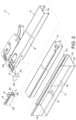
- a slide rail assembly 20 includes a first rail 22, a second rail 24, a blocking structure 26 and a base 28.
- the slide rail assembly 20 further comprises a fitting member.
- the fitting member is illustrated as a blocking member 30.
- the first rail 22 has a rail 22a, an extension portion 22b and a perpendicular portion 22c.
- the extension portion 22b is connected between the rail 22a and the perpendicular portion 22c.
- the blocking structure 26 is arranged on one of the first rail 22 and the second rail 24.
- the blocking structure 26 is arranged on the extension portion 22b of the first rail 22.
- the blocking structure 26 can be a protrusion or a blocking wall.
- the first rail 22 further has a front portion 23a and a rear portion 23b.
- the blocking structure 26 is arranged adjacent to the front portion 23a of the first rail 22 and located in a space surrounded by the rail 22a, the extension portion 22b and the perpendicular portion 22c.
- the second rail 24 is longitudinally movable relative to the first rail 22.
- the slide rail assembly 20 further comprises a third rail 32 movably mounted between the second rail 24 and (the rail 22a of) the first rail 22.
- the third rail 32 is configured to extend a traveling distance of the second rail 24 relative to the first rail 22.
- the second rail 24 has a front portion 25a and a rear portion 25b. As shown in FIG. 1 , the second rail 24 is located at an extension position E relative to the first rail 22.
- the base 28 is connected to the other one of the first rail 22 and the second rail 24.
- the base 28 can be fixedly connected to the second rail 24.
- the base 28 can be detachably connected to the second rail 24.
- the base 28 be regarded as a part of the second rail 24.
- the base 28 is connected and adjacent to the front portion 25a of the second rail 24.
- the base 28 is arranged along a longitudinal direction, and the base 28 comprises a connecting portion 34 and a plurality of walls.
- the plurality of walls are a first wall 36a, a second wall 36b and a third wall 36c.
- the connecting portion 34 is connected to the first wall 36a.
- the first wall 36a, the second wall 36b and the third wall 36c are connected to a side portion 38 of the second rail 24 through the connecting portion 34.
- the first wall 36a, the second wall 36b and the third wall 36c are bent relative to one another.
- a space S is defined by the first wall 36a, the second wall 36b and the third wall 36c, and the space S is configured to be detachably mounted with the blocking member 30.
- a non-circular outline is formed by the first wall 36a, the second wall 36b and the third wall 36c, and the space S is defined by the non-circular outline.
- the blocking member 30 is detachably mounted on the base 28.
- the blocking member 30 comprises a first portion 30a configured to be mounted in the space S.
- the blocking member 30 further comprises a second portion 30b connected to the first portion 30a.
- a size of the second portion 30b is greater than a size of the first portion 30a and a size of the space S.
- the blocking member 30 is made of non-metallic material, such as plastic or elastic material.
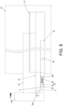
- the slide rail assembly 20 is applicable to a furniture system.
- the furniture system comprises a first furniture member 40 (such as a cabinet) and a second furniture member 42 (such as a drawer) .
- the second furniture member 42 has a front board 42a.
- the first rail 22 is fixedly mounted to the first furniture member 40 and can be regarded as a part of the first furniture member 40.
- the second rail 24 is configured to carry a bottom of the second furniture member 42 and can be regarded as a part of the second furniture member 42.
- the blocking member 30 (also known as fitting member) being mounted on the base 28 enables the second rail 24 to be located at a substantially same position or to reduce noise when the second rail 24 is retracted relative to the first rail 22.
- the blocking member 30 when the blocking member 30 is mounted on the base 28 and the second rail 24 is retracted relative to the first rail 22 from the extension position E along a direction D (e.g., when the second rail 24 is completely retracted relative to the first rail 22), through the blocking member 30 (such as the second portion 30b) abutting against the blocking structure 26 allows the second rail 24 to be located at the one single longitudinally predetermined position (i.e., the one single depth position).
- the second rail 24 is located at a first longitudinal position P1.
- the second rail 24 when the second rail 24 is retracted relative to the first rail 22 from the extension position E along the direction D (e.g., when the second rail 24 is completely retracted relative to the first rail 22), the second rail 24 is able to be substantially located at the first longitudinal position P1 relative to the first rail 22 through the blocking member 30 (such as the second portion 30b) abutting against the blocking structure 26.
- the blocking member 30 is made of plastic or elastic material, the blocking member 30 is able to reduce the noise or to provide a damping effect when the blocking member 30 abuts against the blocking structure 26 (i.e., when the second rail 24 is retracted relative to the first rail 22 and located at the first longitudinal position P1) .
- the furniture system or the slide rail assembly 20 with capability of depth adjustment is desired, or alternatively, an adjusting mechanism for solving tolerance issue between the first rail 22 (or the first furniture member 40) and the second rail 24 (or the second furniture member 42) is desired.
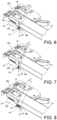
- the aforementioned fitting member can be an adjusting device 44, which is able to be selectively mounted on the base 28.
- the blocking member 30 can be detached from the base 28 first, and then the adjusting device 44 is mounted on the base 28.
- the blocking member 30 and the adjusting device 44 are able to respectively be mounted on the base 28 respectively.
- the blocking member 30 and the adjusting device 44 are mounted in the same position.
- the adjusting device 44 comprises a mounting member 46 and an adjusting member 48.
- the mounting member 46 and the adjusting member 48 are adjustably connected to each other.
- the mounting member 46 and the adjusting member 48 are screwed to each other.
- the mounting member 46 is accommodated and mounted in the space S of the base 28, and the mounting member 46 has a first threaded feature 50.
- the adjusting member 48 comprises a body portion 48a.
- the adjusting member 48 further comprises a head portion 48b connected to the body portion 48a, and a size of the head portion 48b is greater than a size of the body portion 48a.
- the adjusting member 48 connected to the mounting member 46 in an adjustable manner is able to adjust the position of the adjusting member 48 relative to the mounting member 46, such that the length (longitudinal length) of the adjusting device 44 is adjustable. It is noticed that, since the arrangement of other related parts of the slide rail assembly 20 (e.g., the arrangement of the first rail 22, the second rail 24, the blocking structure 26 and the base 28) is illustrated above, related description is omitted herein for simplicity.
- the base 28 is connected and adjacent to the front portion 25a of the second rail 24.
- the adjusting device 44 extends the base 28 by a first length L1.
- the adjusting member 48 is located at a position relative to the mounting member 46, such as a second longitudinal position P2.
- the adjusting member 48 when the adjusting member 48 is rotated clockwise relative to the mounting member 46, the adjusting device 44 is adjusted to extend the base 28 by a second length L2. In the meanwhile, the adjusting member 48 is located at another position relative to the mounting member 46, such as a third longitudinal position P3.
- the adjusting device 44 is adjusted to extend the base 28 by a third length L3.
- the adjusting member 48 is located at another position relative to the mounting member 46, such as a fourth longitudinal position P4.
- the second longitudinal position P2, the third longitudinal position P3 and the fourth longitudinal position P4 are different positions, and the first length L1, second length L2 and the third length L3 are different lengths.
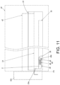
- the adjusting device 44 when the adjusting device 44 is mounted on the base 28 and the adjusting member 48 is not yet adjusted relative to the mounting member 46 or the base 28 (not shown in figures, e.g., the base 28 is able to have a threaded feature corresponding to the adjusting member 48), the adjusting device 44 has the aforesaid first length L1.
- the second rail 24 when the second rail 24 is retracted relative to the first rail 22 from the extension position E along the direction D (e.g., when the second rail 24 is completely retracted relative to the first rail 22), the head portion 48b of the adjusting member 48 abuts against the blocking structure 26 (as shown in FIG. 10 ), such that the second rail 24 is located at a longitudinal position relative to the first rail 22, such as the aforesaid second longitudinal position P2.
- the adjusting device 44 has the aforesaid second length L2.
- the head portion 48b of the adjusting member 48 abuts against the blocking structure 26, such that the second rail 24 is located at another longitudinal position relative to the first rail 22, such as the aforesaid third longitudinal position P3.
- the adjusting member 48 is adjusted relative to the mounting member 46 or the base 28 to have the aforesaid third length L3.
- the head portion 48b of the adjusting member 48 abuts against the blocking structure 26, such that the second rail 24 is located at yet another longitudinal position relative to the first rail 22, such as the aforesaid fourth longitudinal position P4.
- the length of the adjusting device 44 is adjustable and the adjusting device 44 is able to abut against the blocking structure 26.
- the second rail 24 is able to be located at different longitudinal positions (different depth positions), such as the first longitudinal position P1, the second longitudinal position P2, the third longitudinal position P3 and the fourth longitudinal position P4.
- the adjusting member 48 of the adjusting device 44 when the adjusting member 48 of the adjusting device 44 is not yet adjusted relative to the mounting member 46 to allow the adjusting device 44 to have a length (e.g., the first length L1), and when the second rail 24 is retracted relative to the first rail 22 from the extension position E along the direction D (e.g., when the second rail 24 is completely retracted relative to the first rail 22), the head portion 48b of the adjusting member 48 abuts against the blocking structure 26, such that the second rail 24 is located at the same longitudinal position relative to the first rail 22, such as the second longitudinal position P2.
- a length e.g., the first length L1
- the head portion 48b of the adjusting member 48 abuts against the blocking structure 26, such that the second rail 24 is located at the same longitudinal position relative to the first rail 22, such as the second longitudinal position P2.
- the adjusting member 48 needs to be adjusted relative to the mounting member 46 for allowing the second rail 24 to be located at another longitudinal position (such as the third longitudinal position P3 or the fourth longitudinal position P4) different from the second longitudinal position P2 when the second rail 24 is retracted relative to the first rail 22.
- the embodiments of the present invention include following features:
Landscapes
- Drawers Of Furniture (AREA)
Claims (3)
- Ensemble de glissières (20) comprenant :un premier rail (22);un second rail (24) mobile longitudinalement par rapport au premier rail (22);une structure de blocage (26) disposée sur le premier rail (22);une base (28) reliée au second rail (24); etun élément de fixation monté de manière amovible sur le second rail (24), l'élément de fixation étant un dispositif de réglage (44);dans lequel le dispositif de réglage (44) comprend un élément de montage (46) et un élément de réglage (48), l'élément de réglage (48) comprend une partie de tête (48b) reliée à une partie de corps (48a) et une taille de la partie de tête (48b) est supérieure à une taille de la partie de corps (48a), l'élément de montage (46) comprend une première caractéristique filetée (50), l'élément de montage (46) et l'élément de réglage (48) sont reliés l'un à l'autre d'une manière réglable, de sorte que la position de l'élément de réglage (48) peut être ajustée par rapport à l'élément de montage (46) de sorte que la longueur longitudinale du dispositif de réglage (44) est réglable, l'élément de montage (46) peut être monté sur la base (28), l'élément de réglage (48) bute contre la structure de blocage (26) lorsque le second rail (24) est rétracté par rapport au premier rail (22);lorsque l'élément de réglage (48) est vissé à travers une deuxième caractéristique filetée (48c) à la première caractéristique filetée (50) de l'élément de montage (46), la partie de tête (48b) est située hors d'un espace S de la base (28);dans lequel l'élément de montage (46) est logé dans ledit espace S de la base (28);lorsque l'élément de réglage (48) est tourné dans le sens des aiguilles d'une montre ou dans le sens inverse, le dispositif de réglage (44) est ajusté pour étendre la base (28) de différentes longueurs;dans lequel, lorsque le dispositif de réglage (44) est monté sur le second rail (24) et que le second rail (24) est rétracté par rapport au premier rail (22), le dispositif de réglage (44) en butée contre la structure de blocage (26) permet au second rail (24) d'être placé à une seule position longitudinale prédéterminée ou à plusieurs positions longitudinales prédéterminées par rapport au premier rail (22);dans lequel le dispositif de réglage (44) est monté de manière amovible sur la base (28).
- L'ensemble de glissières (20) de la revendication 1, caractérisé en ce que l'élément de montage (46) et l'élément de réglage (48) sont vissés l'un à l'autre.
- L'ensemble de glissières (20) de la revendication 1 ou 2, caractérisé en ce que la base (28) comprend une partie de connexion (34) et une pluralité de parois (36a, 36b, 36c), la pluralité de parois (36a, 36b, 36c) sont connectées à l'autre du premier rail (22) et du second rail (24) à travers la partie de connexion (34), et un espace est défini par la pluralité de parois (36a, 36b, 36c), dans lequel un contour non circulaire est formé par la pluralité de parois (36a, 36b, 36c) et configuré pour être monté de manière amovible avec l'élément de fixation, chacun du premier rail (22) et du second rail (24) comprend une partie avant (23a, 25a) et une partie arrière (23b, 25b), la base (28) est reliée à l'autre du premier rail (22) et du second rail (24) et est située à côté de la partie avant (23a, 25a).
Applications Claiming Priority (1)
| Application Number | Priority Date | Filing Date | Title |
|---|---|---|---|
| TW107106907A TWI694791B (zh) | 2018-02-27 | 2018-02-27 | 用於傢俱的滑軌總成 |
Publications (2)
| Publication Number | Publication Date |
|---|---|
| EP3530147A1 EP3530147A1 (fr) | 2019-08-28 |
| EP3530147B1 true EP3530147B1 (fr) | 2023-05-17 |
Family
ID=63442573
Family Applications (1)
| Application Number | Title | Priority Date | Filing Date |
|---|---|---|---|
| EP18191393.0A Active EP3530147B1 (fr) | 2018-02-27 | 2018-08-29 | Ensemble de rails de glissement |
Country Status (4)
| Country | Link |
|---|---|
| US (1) | US10517396B2 (fr) |
| EP (1) | EP3530147B1 (fr) |
| JP (1) | JP6674516B2 (fr) |
| TW (1) | TWI694791B (fr) |
Families Citing this family (4)
| Publication number | Priority date | Publication date | Assignee | Title |
|---|---|---|---|---|
| DE102018108647A1 (de) * | 2018-04-11 | 2019-10-17 | Paul Hettich Gmbh & Co. Kg | Auszugsführung und Schubkastenserie |
| TWI670031B (zh) * | 2018-09-27 | 2019-09-01 | 川湖科技股份有限公司 | 滑軌機構 |
| DE102020101514A1 (de) | 2020-01-23 | 2021-07-29 | Paul Hettich Gmbh & Co. Kg | Auszugsführung und Möbel |
| CN112890475B (zh) * | 2021-02-03 | 2022-06-14 | 博洛尼家居用品湖北有限公司 | 一种卡紧块及抽屉滑轨组件 |
Citations (5)
| Publication number | Priority date | Publication date | Assignee | Title |
|---|---|---|---|---|
| WO2012084593A1 (fr) * | 2010-12-22 | 2012-06-28 | Paul Hettich Gmbh & Co. Kg | Dispositif d'ouverture et de fermeture pour éléments mobiles de meubles, ainsi que dispositif d'éjection |
| KR101454917B1 (ko) * | 2014-07-25 | 2014-11-12 | 장근대 | 서랍의 레일장치 |
| WO2015120493A1 (fr) * | 2014-02-13 | 2015-08-20 | Julius Blum Gmbh | Guide télescopique pour élément de meuble mobile |
| WO2016177732A1 (fr) * | 2015-05-04 | 2016-11-10 | Paul Hettich Gmbh & Co. Kg | Dispositif et procédé pour immobiliser un élément coulissant |
| WO2018011356A1 (fr) * | 2016-07-15 | 2018-01-18 | Paul Hettich Gmbh & Co. Kg | Dispositifd'entraînement d'un élément de meuble mobile, et procédé d'ouverture et de fermeture d'un élément de meuble mobile |
Family Cites Families (24)
| Publication number | Priority date | Publication date | Assignee | Title |
|---|---|---|---|---|
| US3074766A (en) * | 1960-08-22 | 1963-01-22 | Jonathan Mfg Company | Shock resisting support for slide structure for drawers, shelves and the like |
| DE9310582U1 (de) * | 1993-07-15 | 1993-09-23 | Paul Hettich GmbH & Co, 32278 Kirchlengern | Rasteinrichtung fuer schubkaesten o.dgl. |
| AU2003206613A1 (en) * | 2003-01-03 | 2004-07-29 | Zimmer, Gunther | Guide system comprising a pneumatic deceleration device |
| AT502943B1 (de) * | 2005-04-01 | 2011-07-15 | Blum Gmbh Julius | Dämpfvorrichtung für bewegbare möbelteile |
| MY146313A (en) * | 2005-10-11 | 2012-07-31 | Harn Marketing Sdn Bhd | Sliding guide rail system for a drawer |
| AT10097U1 (de) * | 2007-04-30 | 2008-09-15 | Blum Gmbh Julius | Federpuffer für ein möbel |
| US8413298B2 (en) * | 2008-01-22 | 2013-04-09 | Grass America, Inc. | Universal damping mechanism |
| DE202008006909U1 (de) * | 2008-05-21 | 2008-07-31 | Lautenschläger, Horst | Dämpfungseinrichtung für Möbeltüren |
| AT506879B1 (de) | 2008-06-10 | 2011-07-15 | Blum Gmbh Julius | Vorrichtung zum lösbaren kuppeln einer schublade mit einer schiene einer schubladenausziehführung |
| ITMI20090157U1 (it) | 2009-05-13 | 2010-11-14 | Agostino Ferrari Spa | Guida con push-pull per mobili |
| DE202009017319U1 (de) * | 2009-12-21 | 2011-05-05 | Grass Gmbh | Möbel und Vorrichtung für ein Möbel |
| AT509415B1 (de) * | 2010-02-03 | 2013-12-15 | Blum Gmbh Julius | Anordnung mit einer Schublade und einer Ausziehführung für eine Schublade mit zumindest zwei Einrastpositionen |
| US20120017414A1 (en) * | 2010-07-23 | 2012-01-26 | Cerniglia Anthony J | Cabinet drawer support system |
| US8876230B2 (en) * | 2011-09-24 | 2014-11-04 | Hardware Resources, Inc. | Durable drawer retainer apparatus and method of use |
| CN102871381B (zh) * | 2012-10-11 | 2014-12-10 | 伍志勇 | 抽屉的调节装置 |
| DE202012012265U1 (de) | 2012-12-21 | 2014-03-24 | Grass Gmbh | Vorrichtung zur Einstellung eines in einem Möbelkorpus aufgenommenen Möbelteils, Führungsvorrichtung zur Bewegung eines bewegbaren Möbelteils sowie Möbel mit einer Vorrichtung zur Einstellung eines in einem Möbelkorpus aufgenommenen Möbelteils |
| US10149539B2 (en) * | 2013-11-22 | 2018-12-11 | Hardware Resources, Inc. | Undermount drawer slide position adjustment apparatus and method of use |
| AT515265B1 (de) | 2014-01-09 | 2018-07-15 | Blum Gmbh Julius | Schubladenausziehführung |
| CN104886952B (zh) * | 2014-03-05 | 2017-06-23 | 川湖科技股份有限公司 | 具有阻尼机构的自闭合滑轨总成 |
| TWI539917B (zh) | 2015-11-12 | 2016-07-01 | 川湖科技股份有限公司 | 滑軌總成 |
| TWI572304B (zh) * | 2016-03-31 | 2017-03-01 | 川湖科技股份有限公司 | 用於傢俱組件的驅動機構及方法 |
| TWI610640B (zh) * | 2017-03-07 | 2018-01-11 | 川湖科技股份有限公司 | 具有緩衝功能的連接機構與滑軌總成 |
| TWI616164B (zh) * | 2017-03-07 | 2018-03-01 | 川湖科技股份有限公司 | 用於傢俱部件的連接機構與滑軌總成 |
| US10314396B2 (en) * | 2017-09-27 | 2019-06-11 | Nan Juen International Co., Ltd. | Quick detachable slide rail and drawer mounting structure |
-
2018
- 2018-02-27 TW TW107106907A patent/TWI694791B/zh active
- 2018-07-17 US US16/036,958 patent/US10517396B2/en active Active
- 2018-08-29 EP EP18191393.0A patent/EP3530147B1/fr active Active
- 2018-09-14 JP JP2018172043A patent/JP6674516B2/ja active Active
Patent Citations (5)
| Publication number | Priority date | Publication date | Assignee | Title |
|---|---|---|---|---|
| WO2012084593A1 (fr) * | 2010-12-22 | 2012-06-28 | Paul Hettich Gmbh & Co. Kg | Dispositif d'ouverture et de fermeture pour éléments mobiles de meubles, ainsi que dispositif d'éjection |
| WO2015120493A1 (fr) * | 2014-02-13 | 2015-08-20 | Julius Blum Gmbh | Guide télescopique pour élément de meuble mobile |
| KR101454917B1 (ko) * | 2014-07-25 | 2014-11-12 | 장근대 | 서랍의 레일장치 |
| WO2016177732A1 (fr) * | 2015-05-04 | 2016-11-10 | Paul Hettich Gmbh & Co. Kg | Dispositif et procédé pour immobiliser un élément coulissant |
| WO2018011356A1 (fr) * | 2016-07-15 | 2018-01-18 | Paul Hettich Gmbh & Co. Kg | Dispositifd'entraînement d'un élément de meuble mobile, et procédé d'ouverture et de fermeture d'un élément de meuble mobile |
Also Published As
| Publication number | Publication date |
|---|---|
| EP3530147A1 (fr) | 2019-08-28 |
| US20190261773A1 (en) | 2019-08-29 |
| TWI694791B (zh) | 2020-06-01 |
| TW201936088A (zh) | 2019-09-16 |
| JP2019146952A (ja) | 2019-09-05 |
| JP6674516B2 (ja) | 2020-04-01 |
| US10517396B2 (en) | 2019-12-31 |
Similar Documents
| Publication | Publication Date | Title |
|---|---|---|
| EP3530147B1 (fr) | Ensemble de rails de glissement | |
| EP3154320B1 (fr) | Ensemble rail coulissant et son dispositif de support | |
| EP3398481B1 (fr) | Ensemble de rails de glissement | |
| US10568425B2 (en) | Furniture system and slide rail assembly thereof | |
| EP3387949B1 (fr) | Ensemble de rails de glissement | |
| EP3352547B1 (fr) | Ensemble de rails de glissement | |
| EP2912969A1 (fr) | Dispositif de fixation ou de détachement de coulisseau pour tiroir | |
| EP3225132B1 (fr) | Mécanisme et procédé de guidage d'éléments de meubles | |
| EP3332670B1 (fr) | Dispositif de fixation reglable de glissieres telescopiques de tiroirs | |
| EP3782513B1 (fr) | Ensemble rail coulissant autorisant un jeu latéral | |
| EP2807951A2 (fr) | Appareil de limitation de mouvement pour ensemble coulissant | |
| US20130328468A1 (en) | Unknown | |
| EP3378354B1 (fr) | Agencement d'engrenages pour système de meubles | |
| EP3613310B1 (fr) | Mécanisme de réglage pour ensemble de rail coulissant | |
| EP3628190B1 (fr) | Mécanisme de rail de coulissement | |
| EP4321053B1 (fr) | Ensemble rail coulissant | |
| CN110200423B (zh) | 用于家具的滑轨总成 | |
| EP3085270B1 (fr) | Dispositif de réglage vertical et horizontal pour tiroirs | |
| EP2979582B1 (fr) | Ensemble de rail de glissement | |
| CN110960011B (zh) | 滑轨机构 | |
| EP3449767B1 (fr) | Dispositif de fixation reglable de glissieres telescopiques de tiroirs | |
| US20240309681A1 (en) | Slide rail mechanism and adjustment device thereof | |
| CN215255449U (zh) | 一种家具缓冲铰链的可调节装置 | |
| EP3897294A1 (fr) | Guide coulissant télescopique ayant des moyens de réglage de position horizontale et d'inclinaison de tiroir | |
| TW201716000A (zh) | 安裝機構 |
Legal Events
| Date | Code | Title | Description |
|---|---|---|---|
| PUAI | Public reference made under article 153(3) epc to a published international application that has entered the european phase |
Free format text: ORIGINAL CODE: 0009012 |
|
| STAA | Information on the status of an ep patent application or granted ep patent |
Free format text: STATUS: THE APPLICATION HAS BEEN PUBLISHED |
|
| AK | Designated contracting states |
Kind code of ref document: A1 Designated state(s): AL AT BE BG CH CY CZ DE DK EE ES FI FR GB GR HR HU IE IS IT LI LT LU LV MC MK MT NL NO PL PT RO RS SE SI SK SM TR |
|
| AX | Request for extension of the european patent |
Extension state: BA ME |
|
| STAA | Information on the status of an ep patent application or granted ep patent |
Free format text: STATUS: REQUEST FOR EXAMINATION WAS MADE |
|
| 17P | Request for examination filed |
Effective date: 20200217 |
|
| RBV | Designated contracting states (corrected) |
Designated state(s): AL AT BE BG CH CY CZ DE DK EE ES FI FR GB GR HR HU IE IS IT LI LT LU LV MC MK MT NL NO PL PT RO RS SE SI SK SM TR |
|
| STAA | Information on the status of an ep patent application or granted ep patent |
Free format text: STATUS: EXAMINATION IS IN PROGRESS |
|
| 17Q | First examination report despatched |
Effective date: 20200407 |
|
| STAA | Information on the status of an ep patent application or granted ep patent |
Free format text: STATUS: EXAMINATION IS IN PROGRESS |
|
| STAA | Information on the status of an ep patent application or granted ep patent |
Free format text: STATUS: EXAMINATION IS IN PROGRESS |
|
| GRAP | Despatch of communication of intention to grant a patent |
Free format text: ORIGINAL CODE: EPIDOSNIGR1 |
|
| STAA | Information on the status of an ep patent application or granted ep patent |
Free format text: STATUS: GRANT OF PATENT IS INTENDED |
|
| INTG | Intention to grant announced |
Effective date: 20221213 |
|
| GRAS | Grant fee paid |
Free format text: ORIGINAL CODE: EPIDOSNIGR3 |
|
| GRAA | (expected) grant |
Free format text: ORIGINAL CODE: 0009210 |
|
| STAA | Information on the status of an ep patent application or granted ep patent |
Free format text: STATUS: THE PATENT HAS BEEN GRANTED |
|
| AK | Designated contracting states |
Kind code of ref document: B1 Designated state(s): AL AT BE BG CH CY CZ DE DK EE ES FI FR GB GR HR HU IE IS IT LI LT LU LV MC MK MT NL NO PL PT RO RS SE SI SK SM TR |
|
| REG | Reference to a national code |
Ref country code: GB Ref legal event code: FG4D |
|
| REG | Reference to a national code |
Ref country code: DE Ref legal event code: R096 Ref document number: 602018049938 Country of ref document: DE |
|
| REG | Reference to a national code |
Ref country code: CH Ref legal event code: EP |
|
| REG | Reference to a national code |
Ref country code: IE Ref legal event code: FG4D |
|
| REG | Reference to a national code |
Ref country code: AT Ref legal event code: REF Ref document number: 1568092 Country of ref document: AT Kind code of ref document: T Effective date: 20230615 |
|
| REG | Reference to a national code |
Ref country code: LT Ref legal event code: MG9D |
|
| REG | Reference to a national code |
Ref country code: NL Ref legal event code: MP Effective date: 20230517 |
|
| REG | Reference to a national code |
Ref country code: AT Ref legal event code: MK05 Ref document number: 1568092 Country of ref document: AT Kind code of ref document: T Effective date: 20230517 |
|
| PG25 | Lapsed in a contracting state [announced via postgrant information from national office to epo] |
Ref country code: SE Free format text: LAPSE BECAUSE OF FAILURE TO SUBMIT A TRANSLATION OF THE DESCRIPTION OR TO PAY THE FEE WITHIN THE PRESCRIBED TIME-LIMIT Effective date: 20230517 Ref country code: PT Free format text: LAPSE BECAUSE OF FAILURE TO SUBMIT A TRANSLATION OF THE DESCRIPTION OR TO PAY THE FEE WITHIN THE PRESCRIBED TIME-LIMIT Effective date: 20230918 Ref country code: NO Free format text: LAPSE BECAUSE OF FAILURE TO SUBMIT A TRANSLATION OF THE DESCRIPTION OR TO PAY THE FEE WITHIN THE PRESCRIBED TIME-LIMIT Effective date: 20230817 Ref country code: NL Free format text: LAPSE BECAUSE OF FAILURE TO SUBMIT A TRANSLATION OF THE DESCRIPTION OR TO PAY THE FEE WITHIN THE PRESCRIBED TIME-LIMIT Effective date: 20230517 Ref country code: ES Free format text: LAPSE BECAUSE OF FAILURE TO SUBMIT A TRANSLATION OF THE DESCRIPTION OR TO PAY THE FEE WITHIN THE PRESCRIBED TIME-LIMIT Effective date: 20230517 Ref country code: AT Free format text: LAPSE BECAUSE OF FAILURE TO SUBMIT A TRANSLATION OF THE DESCRIPTION OR TO PAY THE FEE WITHIN THE PRESCRIBED TIME-LIMIT Effective date: 20230517 |
|
| PGFP | Annual fee paid to national office [announced via postgrant information from national office to epo] |
Ref country code: IE Payment date: 20230821 Year of fee payment: 6 Ref country code: GB Payment date: 20230824 Year of fee payment: 6 |
|
| PG25 | Lapsed in a contracting state [announced via postgrant information from national office to epo] |
Ref country code: GR Free format text: LAPSE BECAUSE OF FAILURE TO SUBMIT A TRANSLATION OF THE DESCRIPTION OR TO PAY THE FEE WITHIN THE PRESCRIBED TIME-LIMIT Effective date: 20230818 Ref country code: RS Free format text: LAPSE BECAUSE OF FAILURE TO SUBMIT A TRANSLATION OF THE DESCRIPTION OR TO PAY THE FEE WITHIN THE PRESCRIBED TIME-LIMIT Effective date: 20230517 Ref country code: PL Free format text: LAPSE BECAUSE OF FAILURE TO SUBMIT A TRANSLATION OF THE DESCRIPTION OR TO PAY THE FEE WITHIN THE PRESCRIBED TIME-LIMIT Effective date: 20230517 Ref country code: LV Free format text: LAPSE BECAUSE OF FAILURE TO SUBMIT A TRANSLATION OF THE DESCRIPTION OR TO PAY THE FEE WITHIN THE PRESCRIBED TIME-LIMIT Effective date: 20230517 Ref country code: LT Free format text: LAPSE BECAUSE OF FAILURE TO SUBMIT A TRANSLATION OF THE DESCRIPTION OR TO PAY THE FEE WITHIN THE PRESCRIBED TIME-LIMIT Effective date: 20230517 Ref country code: IS Free format text: LAPSE BECAUSE OF FAILURE TO SUBMIT A TRANSLATION OF THE DESCRIPTION OR TO PAY THE FEE WITHIN THE PRESCRIBED TIME-LIMIT Effective date: 20230917 Ref country code: HR Free format text: LAPSE BECAUSE OF FAILURE TO SUBMIT A TRANSLATION OF THE DESCRIPTION OR TO PAY THE FEE WITHIN THE PRESCRIBED TIME-LIMIT Effective date: 20230517 |
|
| PGFP | Annual fee paid to national office [announced via postgrant information from national office to epo] |
Ref country code: DE Payment date: 20230527 Year of fee payment: 6 |
|
| PG25 | Lapsed in a contracting state [announced via postgrant information from national office to epo] |
Ref country code: FI Free format text: LAPSE BECAUSE OF FAILURE TO SUBMIT A TRANSLATION OF THE DESCRIPTION OR TO PAY THE FEE WITHIN THE PRESCRIBED TIME-LIMIT Effective date: 20230517 |
|
| PG25 | Lapsed in a contracting state [announced via postgrant information from national office to epo] |
Ref country code: SK Free format text: LAPSE BECAUSE OF FAILURE TO SUBMIT A TRANSLATION OF THE DESCRIPTION OR TO PAY THE FEE WITHIN THE PRESCRIBED TIME-LIMIT Effective date: 20230517 |
|
| PG25 | Lapsed in a contracting state [announced via postgrant information from national office to epo] |
Ref country code: SM Free format text: LAPSE BECAUSE OF FAILURE TO SUBMIT A TRANSLATION OF THE DESCRIPTION OR TO PAY THE FEE WITHIN THE PRESCRIBED TIME-LIMIT Effective date: 20230517 Ref country code: SK Free format text: LAPSE BECAUSE OF FAILURE TO SUBMIT A TRANSLATION OF THE DESCRIPTION OR TO PAY THE FEE WITHIN THE PRESCRIBED TIME-LIMIT Effective date: 20230517 Ref country code: RO Free format text: LAPSE BECAUSE OF FAILURE TO SUBMIT A TRANSLATION OF THE DESCRIPTION OR TO PAY THE FEE WITHIN THE PRESCRIBED TIME-LIMIT Effective date: 20230517 Ref country code: EE Free format text: LAPSE BECAUSE OF FAILURE TO SUBMIT A TRANSLATION OF THE DESCRIPTION OR TO PAY THE FEE WITHIN THE PRESCRIBED TIME-LIMIT Effective date: 20230517 Ref country code: DK Free format text: LAPSE BECAUSE OF FAILURE TO SUBMIT A TRANSLATION OF THE DESCRIPTION OR TO PAY THE FEE WITHIN THE PRESCRIBED TIME-LIMIT Effective date: 20230517 Ref country code: CZ Free format text: LAPSE BECAUSE OF FAILURE TO SUBMIT A TRANSLATION OF THE DESCRIPTION OR TO PAY THE FEE WITHIN THE PRESCRIBED TIME-LIMIT Effective date: 20230517 |
|
| REG | Reference to a national code |
Ref country code: DE Ref legal event code: R097 Ref document number: 602018049938 Country of ref document: DE |
|
| PG25 | Lapsed in a contracting state [announced via postgrant information from national office to epo] |
Ref country code: MC Free format text: LAPSE BECAUSE OF FAILURE TO SUBMIT A TRANSLATION OF THE DESCRIPTION OR TO PAY THE FEE WITHIN THE PRESCRIBED TIME-LIMIT Effective date: 20230517 |
|
| PLBE | No opposition filed within time limit |
Free format text: ORIGINAL CODE: 0009261 |
|
| STAA | Information on the status of an ep patent application or granted ep patent |
Free format text: STATUS: NO OPPOSITION FILED WITHIN TIME LIMIT |
|
| REG | Reference to a national code |
Ref country code: CH Ref legal event code: PL |
|
| PG25 | Lapsed in a contracting state [announced via postgrant information from national office to epo] |
Ref country code: MC Free format text: LAPSE BECAUSE OF FAILURE TO SUBMIT A TRANSLATION OF THE DESCRIPTION OR TO PAY THE FEE WITHIN THE PRESCRIBED TIME-LIMIT Effective date: 20230517 |
|
| PG25 | Lapsed in a contracting state [announced via postgrant information from national office to epo] |
Ref country code: LU Free format text: LAPSE BECAUSE OF NON-PAYMENT OF DUE FEES Effective date: 20230829 |
|
| 26N | No opposition filed |
Effective date: 20240220 |
|
| PG25 | Lapsed in a contracting state [announced via postgrant information from national office to epo] |
Ref country code: LU Free format text: LAPSE BECAUSE OF NON-PAYMENT OF DUE FEES Effective date: 20230829 Ref country code: CH Free format text: LAPSE BECAUSE OF NON-PAYMENT OF DUE FEES Effective date: 20230831 |
|
| PG25 | Lapsed in a contracting state [announced via postgrant information from national office to epo] |
Ref country code: SI Free format text: LAPSE BECAUSE OF FAILURE TO SUBMIT A TRANSLATION OF THE DESCRIPTION OR TO PAY THE FEE WITHIN THE PRESCRIBED TIME-LIMIT Effective date: 20230517 |
|
| REG | Reference to a national code |
Ref country code: BE Ref legal event code: MM Effective date: 20230831 |
|
| PG25 | Lapsed in a contracting state [announced via postgrant information from national office to epo] |
Ref country code: SI Free format text: LAPSE BECAUSE OF FAILURE TO SUBMIT A TRANSLATION OF THE DESCRIPTION OR TO PAY THE FEE WITHIN THE PRESCRIBED TIME-LIMIT Effective date: 20230517 Ref country code: IT Free format text: LAPSE BECAUSE OF FAILURE TO SUBMIT A TRANSLATION OF THE DESCRIPTION OR TO PAY THE FEE WITHIN THE PRESCRIBED TIME-LIMIT Effective date: 20230517 |
|
| PG25 | Lapsed in a contracting state [announced via postgrant information from national office to epo] |
Ref country code: FR Free format text: LAPSE BECAUSE OF NON-PAYMENT OF DUE FEES Effective date: 20230831 |
|
| PG25 | Lapsed in a contracting state [announced via postgrant information from national office to epo] |
Ref country code: BE Free format text: LAPSE BECAUSE OF NON-PAYMENT OF DUE FEES Effective date: 20230831 |
|
| REG | Reference to a national code |
Ref country code: DE Ref legal event code: R082 Ref document number: 602018049938 Country of ref document: DE Representative=s name: STRAUS, ALEXANDER, DIPL.-CHEM.UNIV. DR.PHIL., DE |