EP2979582B1 - Ensemble de rail de glissement - Google Patents
Ensemble de rail de glissement Download PDFInfo
- Publication number
- EP2979582B1 EP2979582B1 EP14179234.1A EP14179234A EP2979582B1 EP 2979582 B1 EP2979582 B1 EP 2979582B1 EP 14179234 A EP14179234 A EP 14179234A EP 2979582 B1 EP2979582 B1 EP 2979582B1
- Authority
- EP
- European Patent Office
- Prior art keywords
- rail
- assembly
- arm
- slide rail
- bracket assembly
- Prior art date
- Legal status (The legal status is an assumption and is not a legal conclusion. Google has not performed a legal analysis and makes no representation as to the accuracy of the status listed.)
- Active
Links
- 230000000903 blocking effect Effects 0.000 claims description 33
- 238000005452 bending Methods 0.000 claims description 6
- 230000000149 penetrating effect Effects 0.000 claims description 3
- 230000007246 mechanism Effects 0.000 description 4
- 238000013461 design Methods 0.000 description 3
- 230000000712 assembly Effects 0.000 description 2
- 238000000429 assembly Methods 0.000 description 2
- 238000012423 maintenance Methods 0.000 description 2
- 238000011161 development Methods 0.000 description 1
- 238000000034 method Methods 0.000 description 1
- 238000012986 modification Methods 0.000 description 1
- 230000004048 modification Effects 0.000 description 1
Images


Classifications
-
- H—ELECTRICITY
- H05—ELECTRIC TECHNIQUES NOT OTHERWISE PROVIDED FOR
- H05K—PRINTED CIRCUITS; CASINGS OR CONSTRUCTIONAL DETAILS OF ELECTRIC APPARATUS; MANUFACTURE OF ASSEMBLAGES OF ELECTRICAL COMPONENTS
- H05K7/00—Constructional details common to different types of electric apparatus
- H05K7/14—Mounting supporting structure in casing or on frame or rack
- H05K7/1485—Servers; Data center rooms, e.g. 19-inch computer racks
- H05K7/1488—Cabinets therefor, e.g. chassis or racks or mechanical interfaces between blades and support structures
- H05K7/1489—Cabinets therefor, e.g. chassis or racks or mechanical interfaces between blades and support structures characterized by the mounting of blades therein, e.g. brackets, rails, trays
-
- A—HUMAN NECESSITIES
- A47—FURNITURE; DOMESTIC ARTICLES OR APPLIANCES; COFFEE MILLS; SPICE MILLS; SUCTION CLEANERS IN GENERAL
- A47B—TABLES; DESKS; OFFICE FURNITURE; CABINETS; DRAWERS; GENERAL DETAILS OF FURNITURE
- A47B88/00—Drawers for tables, cabinets or like furniture; Guides for drawers
- A47B88/50—Safety devices or the like for drawers
- A47B88/57—Safety devices or the like for drawers preventing complete withdrawal of the drawer
Definitions
- the invention relates to a slide rail assembly, and more particularly, to a slide rail assembly ensuring that one rail of the slide rail assembly does not dislocate from the other rail when being pulled and moved with respect to the other rail to a predetermined position.
- slide rail assemblies are respectively configured on the two corresponding sides of a server chassis for rack server systems.
- a bracket assembly connected with the slide rail assembly, the slide rail assembly is correspondingly mounted on the rack so that the chassis may be mounted on the rack.
- U.S. Patent No. 8,371,454 B2 disclosed a bracket assembly for a rack. It may be understood from the description and drawings (e.g. FIG. 8 ) that when a user assembles the bracket components to the post 86 of the rack 84, the user may penetrate the mounting member 32 of the end plate 14 of the bracket 10 through the post hole 88 of the rack 84, and by pressing the elastic leg 42 of the arm member 40 against the base 30, the fastening arm 44 of the arm member 40 retains an elastic force relative to the elastic leg 42 so that the fastening portion 46 of the fastening arm 44 retains elastic force and blocks in front of the rack 84 to ensure that the bracket components do not dislocate from the rack 84
- a slide rail assembly according to the preamble of claim 1 or 11 is known from US 2002/074914 A1 .
- conventional slide rail assemblies may also have engaging mechanisms configured between the two corresponding rails so as to provide a protection mechanism, by which a rail may be blocked at a predetermined position and not be dislocated from the other rail when the rail is moved longitudinally with respect to the other rail, the structural design of the engaging mechanism is usually over-complicated and the operations to disable the protection mechanism are inconvenient for the user.
- the present invention is a slide rail assembly that ensures that one rail of the slide rail assembly does not dislocate from the other rail when being pulled and moved with respect to the other rail to a predetermined position.
- the invention provides a slide rail assembly according to claim 1.
- the arm member of the bracket assembly further comprises a first arm section and a second arm section bending from the first arm section, wherein the first arm section comprises the blocking portion and the second arm section extends beyond the rack by a distance and faces the rack.
- the side plate of the bracket assembly comprises a base, wherein the bracket assembly further comprises a connection member, and wherein the connection member pivotally connects the arm member to the base of the side plate.
- the location of the blocking portion of the bracket assembly extends beyond the end plate by a distance.
- the first rail comprises an end, wherein the side plate of the bracket assembly is connected to the end of the first rail.
- the engaging member further comprises a base plate connected to the second rail and an inclining portion bending from the base plate, wherein the contact portion is located on the inclining portion, and wherein when the second rail is blocked at the predetermined position, the inclining portion is able to be pressed to separate the contact portion of the engaging member from the blocking portion of the arm member.
- the contact portion comprises a slant corresponding to the arm member, wherein when the second rail is moved along an opposite direction with respect to the first rail and drives the slant to contact the arm member, the inclining portion of the engaging member is pressed so that the contact portion of the engaging member can pass the arm member.
- the second rail comprises a rail hole and a hole edge adjacent to the rail hole, wherein the engaging member further comprises a supporting portion connected to the inclining portion and bent towards the second rail, and wherein the supporting portion comprises a blocking wing penetrating the rail hole and blocked by the hole edge.
- the arm member further comprises an arm hole, wherein the blocking portion is an edge adjacent to the arm hole, wherein the contact portion of the engaging member is a protrusion, and wherein when the second rail is pulled and moved along the direction with respect to the first rail to the predetermined position, the protrusion of the engaging member is located at the arm hole of the arm member and is blocked by the edge of the arm member to block the second rail at the predetermined position.
- the invention also provides a slide rail assembly according to claim 11.
- the first rail comprises a base, wherein a connection member pivotally connects the arm member to the base of the first rail.
- a feature of the embodiments of invention is that the blocking portion of the arm member blocks the contact portion of the engaging member so that the second rail is blocked at a predetermined position and does not dislocate from the first rail when the second rail of the slide rail assembly is pulled and moved along the direction with respect to the first rail to the predetermined position.
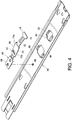
- FIG. 1 shows a slide rail assembly 10 mounted to a rack by means of at least one bracket assembly according to an embodiment of the present invention.
- the two opposite ends of the slide rail assembly 10 are mounted to a first post 16 and a second post 18 of the rack by means of a first bracket assembly 12 and a second bracket assembly 14, respectively.
- the first post 16 and the second post 18 each comprises a plurality of post holes 20, wherein the plurality of post holes 20 may be square holes, circular holes, or holes of other shapes. Square holes are used here for an example, but the present invention is not limited thereto. Since the assembled configuration of the second bracket assembly 14 and the second post 18 is generally the same as that of the first bracket assembly 12 and the first post 16, the following descriptions shall only be made for the assembled configuration of the first bracket assembly 12 and the first post 16.
- the first bracket assembly 12 comprises a side plate 22, an end plate 24, an arm member 26, and a mounting member 28.
- the end plate 24 bends from the side plate 22 and more particularly, the end plate 24 is substantially perpendicularly connected to the side plate 22.
- the mounting member 28 is connected to the end plate 24 and may be correspondingly mounted to the post hole 20 of the first post 16.
- the arm member 26 is connected (e.g., movably connected) to the side plate 22 and comprises a blocking portion 30.
- the side plate 22 of the first bracket assembly 12 comprises a base 32 laterally connected to the side plate 22, wherein the first bracket assembly 12 further comprises a connection member 34 pivotally connecting the arm member 26 to the base 32 of the side plate 22 so that the arm member 26 may be operated to rotate with respect to the side plate 22.
- the arm member 26 further comprises a first arm section 36 and a second arm section 38.
- the second arm section 38 bends from the first arm section 36 and more particularly, the second arm section 38 is substantially perpendicular to the first arm section 36.
- the first arm section 36 comprises the blocking portion 30.
- the first arm section 36 further comprises an arm hole 40, wherein the blocking portion 30 is an edge adjacent to the arm hole 40, and wherein the location of the blocking portion 30 extends beyond the end plate 24 by a distance when the arm member 26 is pivotally connected to the base 32 of the side plate 22.
- the arm member 26 further comprises an elastic portion 42 (such as an elastic leg) correspondingly pressing against a portion of the first bracket assembly 12 so that the elastic portion 42 provides an elastic force to the arm member 26.
- the elastic portion 42 extends from the first arm section 36 of the arm member 26 so that the second arm section 38 of the arm member 26 remains correspondingly facing the end plate 24 by means of the elastic force and is located in front of the first post 16 by a distance when the first bracket assembly 12 is mounted to the first post 16 (as shown in FIG. 3 ).
- the slide rail assembly 10 comprises a first rail 44, a second rail 46, and an engaging member 48.
- the first rail 44 is connected to the side plate 22 of the first bracket assembly 12. More particularly, the side plate 22 of the first bracket assembly 12 is connected to an end of the first rail 44 (such as a front end).
- the first rail 44 comprises an upper wall 50, a lower wall 52, and a side wall 54 extending between the upper wall 50 and the lower wall 52, wherein the upper wall 50, the lower wall 52, and the side wall 54 collectively define a longitudinal channel 56.
- the second rail 46 corresponds to and is longitudinally and movably connected to the first rail 44, wherein the second rail 46 comprises a longitudinally extending body 58 corresponding to and longitudinally movable along the longitudinal channel 56 of the first rail 44.
- the longitudinally extending body 58 of the second rail 46 comprises a rail hole 60, a hole edge 62 adjacent to the rail hole 60, and another rail hole 64;
- the engaging member 48 is connected to the longitudinally extending body 58 of the second rail 46 and comprises a first side 73a and a second side 73b that are opposite to each other, wherein the second side 73b faces the longitudinally extending body 58 of the second rail 46.
- the engaging member 48 comprises a contact portion 66 on the first side 73a, wherein the contact portion 66 corresponds in configuration to the blocking portion 30 of the arm member 26 and more particularly, the contact portion 66 is a protrusion, but the present invention is not limited thereto.
- the contact portion 66 comprises a slant 67 and preferably, the engaging member 48 further comprises a base plate 68, an inclining portion 70, and a supporting portion 72.
- the base plate 68 is connected to the longitudinally extending body 58 of the second rail 46; the inclining portion 70 bends from the base plate 68 and is elastic, wherein the contact portion 66 is located on the inclining portion 70; the supporting portion 72 is connected to the inclining portion 70 and bent towards the longitudinally extending body 58 of the second rail 46, wherein the supporting portion 72 comprises at least one blocking wing 74 penetrating the rail hole 60 of the second rail 46 and being blocked by the hole edge 62 to elastically confine the inclining portion 70 at a working position.
- the inclining portion 70 of the engaging member 48 corresponds in position to the another rail hole 64 of the longitudinally extending body 58 of the second rail 46 to be used by a user at discretion.
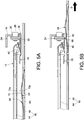
- the user may push the second side 73b of the engaging member 48 through the another rail hole 64 from one side of the second rail 46 (as shown in FIG. 5A ) to adjust the extent of the inclining portion 70 bending from the base plate 68 so that the inclining portion 70 remains at the working position, but the function of the another rail hole 64 is not limited thereto.
- the user may further operate the arm member 26 so that the second arm section 38 of the arm member 26 remains correspondingly blocking in front of the first post 16 by means of the elastic force provided by the elastic portion 42 (i.e., the second arm section 38 of the arm member 26 extends beyond the first post 16 by a distance and faces the first post 16), so as to prevent the slide rail assembly 10 from accidentally dislocating from the first post 16 by means of the blocking by the second arm section 38 of the arm member 26.
- the contact portion 66 (such as a protrusion) of the engaging member 48 is correspondingly located at the arm hole 40 of the arm member 26 and thereby blocked by the blocking portion 30 (such as an edge) of the arm member 26 so that the second rail 46 is blocked at the predetermined position with respect to the first rail 44. Accordingly, the second rail 46 is ensured not to be dislocated from the first rail 44. Therefore, when the second rail 46 is mounted with a chassis (such as a server chassis), the chassis is ensured not to be damaged due to the second rail 46 dislocating from the first rail 44.
- a chassis such as a server chassis
- the contact portion 66 of the engaging member 48 is not blocked by the edge of the end plate 24 when entering the arm hole 40 of the arm member 26, and the blocking portion 30 of the arm member 26 may indeed block the contact portion 66 of the engaging member 48.
- the contact portion 66 of the engaging member 48 is a protrusion and the blocking portion 30 of the arm member 26 is an edge to block the protrusion of the engaging member 48
- the contact portion 66 of the engaging member 48 may be an edge and the blocking portion 30 of the arm member 26 may be a protrusion to block the edge of the engaging member 48 and the present invention is not limited thereto.
- the second rail 46 may be directly pushed from the predetermined position (as in FIG. 5B ) in a withdrawing direction (i.e., opposite to the direction D) so that the second rail 46 may be withdrawn from the predetermined position in the withdrawing direction with respect to the first rail 44 (as in FIG. 5A ).
- the user may directly apply a force F to press the inclining portion 70 of the engaging member 48 so that the contact portion 66 of the engaging member 48 may be dislocated from and no longer blocked by the blocking portion 30 of the arm member 26 (as in FIG. 6A ), and the design of which may be more convenient for the user to operate; under such a condition, the user may further continue to pull and move the second rail 46 along the direction D (as in FIG. 6B ) so that the second rail 46 is dislocated from the first rail 44.
- the user may carry out related maintenance of the slide rail assembly 10 according to this feature, or may further carry out related replacement or maintenance of the chassis when a chassis is mounted on the second rail 46.
- the user may directly push the second rail 46 in the withdrawing direction (i.e., opposite to the direction D) and the slant 67 of the engaging member 48 may thereby be pressed against by the second arm section 38 of the arm member 26 during the withdrawing process (as in FIG. 7 ) so that the inclining portion 70 of the engaging member 48 is correspondingly pressed (as in FIG. 6A ), and the contact portion 66 of the engaging member 48 may subsequently pass the second arm section 38 of the arm member 26.
- the second rail 46 may be withdrawn with respect to the first rail 44.
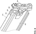
- FIG. 8 shows a slide rail assembly according to another embodiment of the present invention.
- an arm member may be configured at a first rail of the slide rail assembly.
- the slide rail assembly comprises an arm member 200 that is movably connected to an end of a first rail 202 (such as a front end) and comprises a blocking portion 204.
- the first rail 202 comprises a base 206 configured in the vicinity of the end of the first rail 202, wherein a connection member 208 pivotally connects the arm member 200 to the base 206 of the first rail 202.
- a blocking portion 204 of the arm member 200 blocks a contact portion of an engaging member so that a second rail (not shown) is blocked at a predetermined position to ensure that the second rail is not to dislocated from the first rail 202.
Landscapes
- Engineering & Computer Science (AREA)
- Computer Hardware Design (AREA)
- General Engineering & Computer Science (AREA)
- Microelectronics & Electronic Packaging (AREA)
- Drawers Of Furniture (AREA)
Claims (11)
- Ensemble de glissières (10) comprenant un ensemble de support (12), l'ensemble de support (12) comprend une plaque latérale (22) et un élément formant bras (26), l'élément formant bras (26) raccordé à la plaque latérale (22) et comprenant une partie de blocage (30), l'ensemble de glissières (10) caractérisée par le fait qu'elle comprend :un premier rail (44), raccordé à la plaque latérale (22) de l'ensemble de support (12) ;un second rail (46), raccordé de manière longitudinale et mobile au premier rail (44) ; etun élément d'engagement (48), raccordé au second rail (46) et comprenant une partie de contact (66),lorsque le second rail (46) est tiré et déplacé le long d'une direction par rapport au premier rail (44) vers une position prédéterminée, la partie de blocage (30) de l'élément formant bras (26) bloque la partie de contact (66) de l'élément d'engagement (48) de sorte que le second rail (46) est bloqué sur la position prédéterminée, caractérisé en ce que l'ensemble de glissières (10) est montable sur un châssis grâce à au moins un ensemble de support (12), le châssis comprend un trou de montant (20), l'élément formant bras (26) de l'ensemble de support (12) est raccordé de manière mobile à la plaque latérale (22) de l'ensemble de support (12), l'ensemble de support (12) comprend en outre une plaque d'extrémité (24) et un élément de montage (28), la plaque d'extrémité (24) coudée à partir de la plaque latérale (22), et l'élément de montage (28) est raccordé à la plaque d'extrémité (24) et montable sur le trou de montant (20) du châssis.
- Ensemble de glissières (10) selon la revendication 1, caractérisée par le fait quela plaque latérale (22) de l'ensemble de support (12) comprend a base (32), l'ensemble de support (12) comprend en outre un élément de liaison (34), et l'élément de liaison (34) raccorde de manière pivotante l'élément formant bras (26) à la base (32) de la plaque latérale (22).
- Ensemble de glissières (10) selon la revendication 1, caractérisée par le fait quel'emplacement de la partie de blocage (30) de l'ensemble de support (12) s'étend au-delà de la plaque d'extrémité (24) par une distance.
- Ensemble de glissières (10) selon la revendication 1, caractérisée par le fait quele premier rail (44) comprend une extrémité, et la plaque latérale (22) de l'ensemble de support (12) est raccordée à l'extrémité du premier rail (44).
- Ensemble de glissières (10) selon la revendication 1, caractérisée par le fait quel'élément d'engagement (48) comprend en outre une plaque de base (68) raccordé au second rail (46) et une partie inclinée (70) coudée à partir de la plaque de base (68), la partie de contact (66) est située sur la partie inclinée (70), et alors que le second rail (46) est situé à la position prédéterminée, la partie de contact (66) de l'élément d'engagement (48) n'est plus bloquée par la partie de blocage (30) de l'élément formant bras (26) une fois la partie inclinée (70) pressée.
- Ensemble de glissières (10) selon la revendication 5, caractérisée par le fait quela partie de contact (66) comprend un plan incliné (67) correspondant à l'élément formant bras (26), et lorsque le second rail (46) est déplacé le long d'une direction opposée par rapport au premier rail (44) et entraîne le plan incliné (67) à entrer en contact avec l'élément formant bras (26), la partie inclinée (70) de l'élément d'engagement (48) est pressée de sorte que la partie de contact (66) de l'élément d'engagement (48) peut passer l'élément formant bras (26).
- Ensemble de glissières (10) selon la revendication 5, caractérisée par le fait quele second rail (46) comprend un trou de rail (60) et un rebord de trou (62) adjacent au trou de rail (60), l'élément d'engagement (48) comprend en outre une partie de support (72) raccordée à la partie inclinée (70) et courbée vers le second rail (46), et la partie de support (72) comprend une ailette de blocage (74) pénétrant le trou de rail (60) et bloquée par le rebord de trou (62).
- Ensemble de glissières (10) selon la revendication 1, caractérisée par le fait quel'élément formant bras (26) comprend en outre un trou de bras (40), la partie de blocage (30) est un rebord adjacent au trou de bras (40), a partie de contact (66) de l'élément d'engagement (48) est une saillie, et lorsque le second rail (46) est tiré et déplacé le long de la direction par rapport au premier rail (44) vers la position prédéterminée, la saillie de l'élément d'engagement (48) est située au trou de bras (40) de l'élément formant bras (26) et est bloquée par le rebord de l'élément formant bras (26) pour bloquer le second rail (46) à la position prédéterminée.
- Ensemble de glissières (10) selon la revendication 1, caractérisée par le fait quel'élément formant bras (26) de l'ensemble de support (12) comprend en outre une première section de bras (36) et une seconde section de bras (38) coudée à partir de la première section de bras (36), et la première section de bras (36) comprend la partie de blocage (30), et la seconde section de bras (38) s'étend au-delà du châssis par une distance et fait face au châssis lorsque l'ensemble de glissières (10) est monté sur le châssis.
- Ensemble de glissières comprenant un ensemble de support (210) et montable sur un châssis grâce à l'ensemble de support (210), le châssis comprend un trou de montant (20), l'ensemble de support (210) comprend une plaque latérale, une plaque d'extrémité coudée à partir de la plaque latérale, et un élément de montage raccordé à la plaque d'extrémité et montable sur le trou de montant (20) du châssis, caractérisé en ce que l'ensemble de glissières caractérisée par le fait qu'elle comprend :un premier rail (202), raccordé à la plaque latérale de l'ensemble de support (210) et comprenant une extrémité ;un second rail, raccordé de manière longitudinale et mobile au premier rail (202) ;un élément formant bras (200), raccordé de manière mobile à l'extrémité du premier rail (202) et comprenant une partie de blocage (204) ; etun élément d'engagement, raccordé au second rail et comprenant une partie de contact,lorsque le second rail est tiré et déplacé le long d'une direction par rapport au premier rail (202) vers une position prédéterminée, la partie de blocage (204) de l'élément formant bras (200) bloque la partie de contact de l'élément d'engagement de sorte que le second rail est bloqué sur la position prédéterminée.
- Ensemble de glissières selon la revendication 10, caractérisée par le fait quele premier rail (202) comprend une base (206), et un élément de liaison (208) raccorde de manière pivotante l'élément formant bras (200) à la base (206) du premier rail (202).
Priority Applications (1)
| Application Number | Priority Date | Filing Date | Title |
|---|---|---|---|
| EP14179234.1A EP2979582B1 (fr) | 2014-07-31 | 2014-07-31 | Ensemble de rail de glissement |
Applications Claiming Priority (1)
| Application Number | Priority Date | Filing Date | Title |
|---|---|---|---|
| EP14179234.1A EP2979582B1 (fr) | 2014-07-31 | 2014-07-31 | Ensemble de rail de glissement |
Publications (2)
| Publication Number | Publication Date |
|---|---|
| EP2979582A1 EP2979582A1 (fr) | 2016-02-03 |
| EP2979582B1 true EP2979582B1 (fr) | 2017-06-14 |
Family
ID=51257362
Family Applications (1)
| Application Number | Title | Priority Date | Filing Date |
|---|---|---|---|
| EP14179234.1A Active EP2979582B1 (fr) | 2014-07-31 | 2014-07-31 | Ensemble de rail de glissement |
Country Status (1)
| Country | Link |
|---|---|
| EP (1) | EP2979582B1 (fr) |
Families Citing this family (2)
| Publication number | Priority date | Publication date | Assignee | Title |
|---|---|---|---|---|
| TWI598019B (zh) | 2015-07-15 | 2017-09-01 | King Slide Works Co Ltd | 滑軌總成及其托架裝置 |
| TWI598025B (zh) * | 2015-09-18 | 2017-09-01 | King Slide Works Co Ltd | 滑軌總成及其托架裝置 |
Family Cites Families (3)
| Publication number | Priority date | Publication date | Assignee | Title |
|---|---|---|---|---|
| US20020074915A1 (en) * | 2000-12-15 | 2002-06-20 | Shoei-Yuan Shih | Slideout support for server cabinet |
| US7731312B2 (en) * | 2007-04-05 | 2010-06-08 | King Slide Works Co., Ltd. | Retaining mechanism for a slide assembly |
| TWI354528B (en) | 2008-09-01 | 2011-12-11 | King Slide Works Co Ltd | Bracket assembly |
-
2014
- 2014-07-31 EP EP14179234.1A patent/EP2979582B1/fr active Active
Also Published As
| Publication number | Publication date |
|---|---|
| EP2979582A1 (fr) | 2016-02-03 |
Similar Documents
| Publication | Publication Date | Title |
|---|---|---|
| US9480183B2 (en) | Slide rail assembly | |
| US10455938B2 (en) | Slide rail assembly | |
| US9125489B2 (en) | Fixing device for a slide assembly | |
| US9279280B1 (en) | Slide rail assembly | |
| US9066591B2 (en) | Fixing device for a slide assembly | |
| EP3199061B1 (fr) | Ensemble de rail de glissement | |
| EP3135156A1 (fr) | Glissière télescopique | |
| US10292496B2 (en) | Bracket device | |
| US8366217B1 (en) | Installation device for slide assembly | |
| US10617208B2 (en) | Slide rail assembly | |
| US10398228B2 (en) | Slide rail assembly | |
| EP3932257B1 (fr) | Système de meuble | |
| EP2989930B1 (fr) | Ensemble de rail de glissement | |
| EP3417740A1 (fr) | Rail télescopique avec mécanisme de blocage | |
| EP3273757B1 (fr) | Ensemble rail coulissant pour système d'etagère | |
| EP2893838B1 (fr) | Ensemble coulissant comprenant une ferrure ajustable | |
| CN108851656B (zh) | 滑轨总成 | |
| EP2979582B1 (fr) | Ensemble de rail de glissement | |
| EP3041328B1 (fr) | Ensemble de rail de glissement | |
| EP2612572B1 (fr) | Dispositif d'installation d'ensemble coulissant | |
| CN105323999A (zh) | 滑轨总成 | |
| EP2813161B1 (fr) | Dispositif de fixation pour assemblage coulissant | |
| EP3045074A1 (fr) | Ensemble de rail coulissant et dispositif de montage de celui-ci | |
| EP3032930B1 (fr) | Support et dispositif de montage de celui-ci | |
| JP6686203B1 (ja) | ブラケット装置 |
Legal Events
| Date | Code | Title | Description |
|---|---|---|---|
| PUAI | Public reference made under article 153(3) epc to a published international application that has entered the european phase |
Free format text: ORIGINAL CODE: 0009012 |
|
| 17P | Request for examination filed |
Effective date: 20151116 |
|
| AK | Designated contracting states |
Kind code of ref document: A1 Designated state(s): AL AT BE BG CH CY CZ DE DK EE ES FI FR GB GR HR HU IE IS IT LI LT LU LV MC MK MT NL NO PL PT RO RS SE SI SK SM TR |
|
| AX | Request for extension of the european patent |
Extension state: BA ME |
|
| RIC1 | Information provided on ipc code assigned before grant |
Ipc: A47B 88/16 20060101AFI20160916BHEP Ipc: H05K 7/18 20060101ALI20160916BHEP Ipc: H05K 7/14 20060101ALI20160916BHEP |
|
| GRAP | Despatch of communication of intention to grant a patent |
Free format text: ORIGINAL CODE: EPIDOSNIGR1 |
|
| INTG | Intention to grant announced |
Effective date: 20161028 |
|
| GRAS | Grant fee paid |
Free format text: ORIGINAL CODE: EPIDOSNIGR3 |
|
| REG | Reference to a national code |
Ref country code: DE Ref legal event code: R079 Ref document number: 602014010680 Country of ref document: DE Free format text: PREVIOUS MAIN CLASS: A47B0088160000 Ipc: A47B0088570000 |
|
| GRAA | (expected) grant |
Free format text: ORIGINAL CODE: 0009210 |
|
| AK | Designated contracting states |
Kind code of ref document: B1 Designated state(s): AL AT BE BG CH CY CZ DE DK EE ES FI FR GB GR HR HU IE IS IT LI LT LU LV MC MK MT NL NO PL PT RO RS SE SI SK SM TR |
|
| REG | Reference to a national code |
Ref country code: GB Ref legal event code: FG4D |
|
| RIC1 | Information provided on ipc code assigned before grant |
Ipc: A47B 88/57 20170101AFI20170510BHEP |
|
| REG | Reference to a national code |
Ref country code: CH Ref legal event code: EP Ref country code: AT Ref legal event code: REF Ref document number: 900179 Country of ref document: AT Kind code of ref document: T Effective date: 20170615 |
|
| REG | Reference to a national code |
Ref country code: IE Ref legal event code: FG4D |
|
| REG | Reference to a national code |
Ref country code: DE Ref legal event code: R096 Ref document number: 602014010680 Country of ref document: DE |
|
| REG | Reference to a national code |
Ref country code: NL Ref legal event code: MP Effective date: 20170614 |
|
| REG | Reference to a national code |
Ref country code: LT Ref legal event code: MG4D |
|
| PG25 | Lapsed in a contracting state [announced via postgrant information from national office to epo] |
Ref country code: HR Free format text: LAPSE BECAUSE OF FAILURE TO SUBMIT A TRANSLATION OF THE DESCRIPTION OR TO PAY THE FEE WITHIN THE PRESCRIBED TIME-LIMIT Effective date: 20170614 Ref country code: NO Free format text: LAPSE BECAUSE OF FAILURE TO SUBMIT A TRANSLATION OF THE DESCRIPTION OR TO PAY THE FEE WITHIN THE PRESCRIBED TIME-LIMIT Effective date: 20170914 Ref country code: FI Free format text: LAPSE BECAUSE OF FAILURE TO SUBMIT A TRANSLATION OF THE DESCRIPTION OR TO PAY THE FEE WITHIN THE PRESCRIBED TIME-LIMIT Effective date: 20170614 Ref country code: LT Free format text: LAPSE BECAUSE OF FAILURE TO SUBMIT A TRANSLATION OF THE DESCRIPTION OR TO PAY THE FEE WITHIN THE PRESCRIBED TIME-LIMIT Effective date: 20170614 |
|
| REG | Reference to a national code |
Ref country code: AT Ref legal event code: MK05 Ref document number: 900179 Country of ref document: AT Kind code of ref document: T Effective date: 20170614 |
|
| PG25 | Lapsed in a contracting state [announced via postgrant information from national office to epo] |
Ref country code: NL Free format text: LAPSE BECAUSE OF FAILURE TO SUBMIT A TRANSLATION OF THE DESCRIPTION OR TO PAY THE FEE WITHIN THE PRESCRIBED TIME-LIMIT Effective date: 20170614 Ref country code: BG Free format text: LAPSE BECAUSE OF FAILURE TO SUBMIT A TRANSLATION OF THE DESCRIPTION OR TO PAY THE FEE WITHIN THE PRESCRIBED TIME-LIMIT Effective date: 20170914 Ref country code: SE Free format text: LAPSE BECAUSE OF FAILURE TO SUBMIT A TRANSLATION OF THE DESCRIPTION OR TO PAY THE FEE WITHIN THE PRESCRIBED TIME-LIMIT Effective date: 20170614 Ref country code: RS Free format text: LAPSE BECAUSE OF FAILURE TO SUBMIT A TRANSLATION OF THE DESCRIPTION OR TO PAY THE FEE WITHIN THE PRESCRIBED TIME-LIMIT Effective date: 20170614 Ref country code: LV Free format text: LAPSE BECAUSE OF FAILURE TO SUBMIT A TRANSLATION OF THE DESCRIPTION OR TO PAY THE FEE WITHIN THE PRESCRIBED TIME-LIMIT Effective date: 20170614 |
|
| PG25 | Lapsed in a contracting state [announced via postgrant information from national office to epo] |
Ref country code: CZ Free format text: LAPSE BECAUSE OF FAILURE TO SUBMIT A TRANSLATION OF THE DESCRIPTION OR TO PAY THE FEE WITHIN THE PRESCRIBED TIME-LIMIT Effective date: 20170614 Ref country code: SK Free format text: LAPSE BECAUSE OF FAILURE TO SUBMIT A TRANSLATION OF THE DESCRIPTION OR TO PAY THE FEE WITHIN THE PRESCRIBED TIME-LIMIT Effective date: 20170614 Ref country code: AT Free format text: LAPSE BECAUSE OF FAILURE TO SUBMIT A TRANSLATION OF THE DESCRIPTION OR TO PAY THE FEE WITHIN THE PRESCRIBED TIME-LIMIT Effective date: 20170614 Ref country code: EE Free format text: LAPSE BECAUSE OF FAILURE TO SUBMIT A TRANSLATION OF THE DESCRIPTION OR TO PAY THE FEE WITHIN THE PRESCRIBED TIME-LIMIT Effective date: 20170614 Ref country code: RO Free format text: LAPSE BECAUSE OF FAILURE TO SUBMIT A TRANSLATION OF THE DESCRIPTION OR TO PAY THE FEE WITHIN THE PRESCRIBED TIME-LIMIT Effective date: 20170614 |
|
| PG25 | Lapsed in a contracting state [announced via postgrant information from national office to epo] |
Ref country code: IS Free format text: LAPSE BECAUSE OF FAILURE TO SUBMIT A TRANSLATION OF THE DESCRIPTION OR TO PAY THE FEE WITHIN THE PRESCRIBED TIME-LIMIT Effective date: 20171014 Ref country code: SM Free format text: LAPSE BECAUSE OF FAILURE TO SUBMIT A TRANSLATION OF THE DESCRIPTION OR TO PAY THE FEE WITHIN THE PRESCRIBED TIME-LIMIT Effective date: 20170614 Ref country code: IT Free format text: LAPSE BECAUSE OF FAILURE TO SUBMIT A TRANSLATION OF THE DESCRIPTION OR TO PAY THE FEE WITHIN THE PRESCRIBED TIME-LIMIT Effective date: 20170614 Ref country code: ES Free format text: LAPSE BECAUSE OF FAILURE TO SUBMIT A TRANSLATION OF THE DESCRIPTION OR TO PAY THE FEE WITHIN THE PRESCRIBED TIME-LIMIT Effective date: 20170614 Ref country code: PL Free format text: LAPSE BECAUSE OF FAILURE TO SUBMIT A TRANSLATION OF THE DESCRIPTION OR TO PAY THE FEE WITHIN THE PRESCRIBED TIME-LIMIT Effective date: 20170614 |
|
| REG | Reference to a national code |
Ref country code: CH Ref legal event code: PL |
|
| REG | Reference to a national code |
Ref country code: DE Ref legal event code: R097 Ref document number: 602014010680 Country of ref document: DE |
|
| PG25 | Lapsed in a contracting state [announced via postgrant information from national office to epo] |
Ref country code: MC Free format text: LAPSE BECAUSE OF FAILURE TO SUBMIT A TRANSLATION OF THE DESCRIPTION OR TO PAY THE FEE WITHIN THE PRESCRIBED TIME-LIMIT Effective date: 20170614 |
|
| PLBE | No opposition filed within time limit |
Free format text: ORIGINAL CODE: 0009261 |
|
| STAA | Information on the status of an ep patent application or granted ep patent |
Free format text: STATUS: NO OPPOSITION FILED WITHIN TIME LIMIT |
|
| REG | Reference to a national code |
Ref country code: FR Ref legal event code: ST Effective date: 20180330 |
|
| PG25 | Lapsed in a contracting state [announced via postgrant information from national office to epo] |
Ref country code: CH Free format text: LAPSE BECAUSE OF NON-PAYMENT OF DUE FEES Effective date: 20170731 Ref country code: DK Free format text: LAPSE BECAUSE OF FAILURE TO SUBMIT A TRANSLATION OF THE DESCRIPTION OR TO PAY THE FEE WITHIN THE PRESCRIBED TIME-LIMIT Effective date: 20170614 Ref country code: LI Free format text: LAPSE BECAUSE OF NON-PAYMENT OF DUE FEES Effective date: 20170731 |
|
| REG | Reference to a national code |
Ref country code: BE Ref legal event code: MM Effective date: 20170731 |
|
| 26N | No opposition filed |
Effective date: 20180315 |
|
| PG25 | Lapsed in a contracting state [announced via postgrant information from national office to epo] |
Ref country code: FR Free format text: LAPSE BECAUSE OF NON-PAYMENT OF DUE FEES Effective date: 20170816 |
|
| PG25 | Lapsed in a contracting state [announced via postgrant information from national office to epo] |
Ref country code: LU Free format text: LAPSE BECAUSE OF NON-PAYMENT OF DUE FEES Effective date: 20170731 |
|
| PG25 | Lapsed in a contracting state [announced via postgrant information from national office to epo] |
Ref country code: SI Free format text: LAPSE BECAUSE OF FAILURE TO SUBMIT A TRANSLATION OF THE DESCRIPTION OR TO PAY THE FEE WITHIN THE PRESCRIBED TIME-LIMIT Effective date: 20170614 Ref country code: BE Free format text: LAPSE BECAUSE OF NON-PAYMENT OF DUE FEES Effective date: 20170731 |
|
| PG25 | Lapsed in a contracting state [announced via postgrant information from national office to epo] |
Ref country code: MT Free format text: LAPSE BECAUSE OF NON-PAYMENT OF DUE FEES Effective date: 20170731 |
|
| PG25 | Lapsed in a contracting state [announced via postgrant information from national office to epo] |
Ref country code: HU Free format text: LAPSE BECAUSE OF FAILURE TO SUBMIT A TRANSLATION OF THE DESCRIPTION OR TO PAY THE FEE WITHIN THE PRESCRIBED TIME-LIMIT; INVALID AB INITIO Effective date: 20140731 |
|
| PG25 | Lapsed in a contracting state [announced via postgrant information from national office to epo] |
Ref country code: CY Free format text: LAPSE BECAUSE OF FAILURE TO SUBMIT A TRANSLATION OF THE DESCRIPTION OR TO PAY THE FEE WITHIN THE PRESCRIBED TIME-LIMIT Effective date: 20170614 |
|
| PG25 | Lapsed in a contracting state [announced via postgrant information from national office to epo] |
Ref country code: MK Free format text: LAPSE BECAUSE OF FAILURE TO SUBMIT A TRANSLATION OF THE DESCRIPTION OR TO PAY THE FEE WITHIN THE PRESCRIBED TIME-LIMIT Effective date: 20170614 |
|
| PG25 | Lapsed in a contracting state [announced via postgrant information from national office to epo] |
Ref country code: TR Free format text: LAPSE BECAUSE OF FAILURE TO SUBMIT A TRANSLATION OF THE DESCRIPTION OR TO PAY THE FEE WITHIN THE PRESCRIBED TIME-LIMIT Effective date: 20170614 |
|
| PG25 | Lapsed in a contracting state [announced via postgrant information from national office to epo] |
Ref country code: PT Free format text: LAPSE BECAUSE OF FAILURE TO SUBMIT A TRANSLATION OF THE DESCRIPTION OR TO PAY THE FEE WITHIN THE PRESCRIBED TIME-LIMIT Effective date: 20170614 |
|
| PG25 | Lapsed in a contracting state [announced via postgrant information from national office to epo] |
Ref country code: GR Free format text: LAPSE BECAUSE OF FAILURE TO SUBMIT A TRANSLATION OF THE DESCRIPTION OR TO PAY THE FEE WITHIN THE PRESCRIBED TIME-LIMIT Effective date: 20170614 |
|
| PG25 | Lapsed in a contracting state [announced via postgrant information from national office to epo] |
Ref country code: AL Free format text: LAPSE BECAUSE OF FAILURE TO SUBMIT A TRANSLATION OF THE DESCRIPTION OR TO PAY THE FEE WITHIN THE PRESCRIBED TIME-LIMIT Effective date: 20170614 |
|
| PGFP | Annual fee paid to national office [announced via postgrant information from national office to epo] |
Ref country code: IE Payment date: 20230713 Year of fee payment: 10 Ref country code: GB Payment date: 20230706 Year of fee payment: 10 |
|
| PGFP | Annual fee paid to national office [announced via postgrant information from national office to epo] |
Ref country code: DE Payment date: 20230710 Year of fee payment: 10 |