EP3529117B2 - System mit getrennten steuereinheiten für die stelleinheiten einer elektrischen parkbremse - Google Patents
System mit getrennten steuereinheiten für die stelleinheiten einer elektrischen parkbremse Download PDFInfo
- Publication number
- EP3529117B2 EP3529117B2 EP17783461.1A EP17783461A EP3529117B2 EP 3529117 B2 EP3529117 B2 EP 3529117B2 EP 17783461 A EP17783461 A EP 17783461A EP 3529117 B2 EP3529117 B2 EP 3529117B2
- Authority
- EP
- European Patent Office
- Prior art keywords
- ecu
- control unit
- parking brake
- control
- brake actuation
- Prior art date
- Legal status (The legal status is an assumption and is not a legal conclusion. Google has not performed a legal analysis and makes no representation as to the accuracy of the status listed.)
- Active
Links
- 230000005540 biological transmission Effects 0.000 claims description 27
- 238000004891 communication Methods 0.000 claims description 22
- 238000000034 method Methods 0.000 claims description 15
- 238000013461 design Methods 0.000 claims description 4
- 230000001276 controlling effect Effects 0.000 description 8
- 230000003044 adaptive effect Effects 0.000 description 3
- 238000004590 computer program Methods 0.000 description 3
- 230000009347 mechanical transmission Effects 0.000 description 3
- 230000001172 regenerating effect Effects 0.000 description 3
- 230000003213 activating effect Effects 0.000 description 2
- 238000001514 detection method Methods 0.000 description 2
- 241001136792 Alle Species 0.000 description 1
- 101100390736 Danio rerio fign gene Proteins 0.000 description 1
- 101100390738 Mus musculus Fign gene Proteins 0.000 description 1
- 238000013459 approach Methods 0.000 description 1
- 230000008878 coupling Effects 0.000 description 1
- 238000010168 coupling process Methods 0.000 description 1
- 238000005859 coupling reaction Methods 0.000 description 1
- 230000001186 cumulative effect Effects 0.000 description 1
- 230000003247 decreasing effect Effects 0.000 description 1
- 230000000694 effects Effects 0.000 description 1
- 238000011156 evaluation Methods 0.000 description 1
- 239000012530 fluid Substances 0.000 description 1
- 238000009434 installation Methods 0.000 description 1
- 230000001105 regulatory effect Effects 0.000 description 1
- 238000005096 rolling process Methods 0.000 description 1
- 239000004065 semiconductor Substances 0.000 description 1
- 238000000926 separation method Methods 0.000 description 1
Images

Classifications
-
- B—PERFORMING OPERATIONS; TRANSPORTING
- B60—VEHICLES IN GENERAL
- B60T—VEHICLE BRAKE CONTROL SYSTEMS OR PARTS THEREOF; BRAKE CONTROL SYSTEMS OR PARTS THEREOF, IN GENERAL; ARRANGEMENT OF BRAKING ELEMENTS ON VEHICLES IN GENERAL; PORTABLE DEVICES FOR PREVENTING UNWANTED MOVEMENT OF VEHICLES; VEHICLE MODIFICATIONS TO FACILITATE COOLING OF BRAKES
- B60T7/00—Brake-action initiating means
- B60T7/02—Brake-action initiating means for personal initiation
- B60T7/08—Brake-action initiating means for personal initiation hand actuated
- B60T7/085—Brake-action initiating means for personal initiation hand actuated by electrical means, e.g. travel, force sensors
-
- B—PERFORMING OPERATIONS; TRANSPORTING
- B60—VEHICLES IN GENERAL
- B60T—VEHICLE BRAKE CONTROL SYSTEMS OR PARTS THEREOF; BRAKE CONTROL SYSTEMS OR PARTS THEREOF, IN GENERAL; ARRANGEMENT OF BRAKING ELEMENTS ON VEHICLES IN GENERAL; PORTABLE DEVICES FOR PREVENTING UNWANTED MOVEMENT OF VEHICLES; VEHICLE MODIFICATIONS TO FACILITATE COOLING OF BRAKES
- B60T13/00—Transmitting braking action from initiating means to ultimate brake actuator with power assistance or drive; Brake systems incorporating such transmitting means, e.g. air-pressure brake systems
- B60T13/10—Transmitting braking action from initiating means to ultimate brake actuator with power assistance or drive; Brake systems incorporating such transmitting means, e.g. air-pressure brake systems with fluid assistance, drive, or release
- B60T13/66—Electrical control in fluid-pressure brake systems
- B60T13/662—Electrical control in fluid-pressure brake systems characterised by specified functions of the control system components
-
- B—PERFORMING OPERATIONS; TRANSPORTING
- B60—VEHICLES IN GENERAL
- B60T—VEHICLE BRAKE CONTROL SYSTEMS OR PARTS THEREOF; BRAKE CONTROL SYSTEMS OR PARTS THEREOF, IN GENERAL; ARRANGEMENT OF BRAKING ELEMENTS ON VEHICLES IN GENERAL; PORTABLE DEVICES FOR PREVENTING UNWANTED MOVEMENT OF VEHICLES; VEHICLE MODIFICATIONS TO FACILITATE COOLING OF BRAKES
- B60T13/00—Transmitting braking action from initiating means to ultimate brake actuator with power assistance or drive; Brake systems incorporating such transmitting means, e.g. air-pressure brake systems
- B60T13/74—Transmitting braking action from initiating means to ultimate brake actuator with power assistance or drive; Brake systems incorporating such transmitting means, e.g. air-pressure brake systems with electrical assistance or drive
-
- F—MECHANICAL ENGINEERING; LIGHTING; HEATING; WEAPONS; BLASTING
- F16—ENGINEERING ELEMENTS AND UNITS; GENERAL MEASURES FOR PRODUCING AND MAINTAINING EFFECTIVE FUNCTIONING OF MACHINES OR INSTALLATIONS; THERMAL INSULATION IN GENERAL
- F16D—COUPLINGS FOR TRANSMITTING ROTATION; CLUTCHES; BRAKES
- F16D65/00—Parts or details
- F16D65/14—Actuating mechanisms for brakes; Means for initiating operation at a predetermined position
- F16D65/16—Actuating mechanisms for brakes; Means for initiating operation at a predetermined position arranged in or on the brake
- F16D65/18—Actuating mechanisms for brakes; Means for initiating operation at a predetermined position arranged in or on the brake adapted for drawing members together, e.g. for disc brakes
-
- B—PERFORMING OPERATIONS; TRANSPORTING
- B60—VEHICLES IN GENERAL
- B60T—VEHICLE BRAKE CONTROL SYSTEMS OR PARTS THEREOF; BRAKE CONTROL SYSTEMS OR PARTS THEREOF, IN GENERAL; ARRANGEMENT OF BRAKING ELEMENTS ON VEHICLES IN GENERAL; PORTABLE DEVICES FOR PREVENTING UNWANTED MOVEMENT OF VEHICLES; VEHICLE MODIFICATIONS TO FACILITATE COOLING OF BRAKES
- B60T13/00—Transmitting braking action from initiating means to ultimate brake actuator with power assistance or drive; Brake systems incorporating such transmitting means, e.g. air-pressure brake systems
- B60T13/74—Transmitting braking action from initiating means to ultimate brake actuator with power assistance or drive; Brake systems incorporating such transmitting means, e.g. air-pressure brake systems with electrical assistance or drive
- B60T13/745—Transmitting braking action from initiating means to ultimate brake actuator with power assistance or drive; Brake systems incorporating such transmitting means, e.g. air-pressure brake systems with electrical assistance or drive acting on a hydraulic system, e.g. a master cylinder
-
- B—PERFORMING OPERATIONS; TRANSPORTING
- B60—VEHICLES IN GENERAL
- B60T—VEHICLE BRAKE CONTROL SYSTEMS OR PARTS THEREOF; BRAKE CONTROL SYSTEMS OR PARTS THEREOF, IN GENERAL; ARRANGEMENT OF BRAKING ELEMENTS ON VEHICLES IN GENERAL; PORTABLE DEVICES FOR PREVENTING UNWANTED MOVEMENT OF VEHICLES; VEHICLE MODIFICATIONS TO FACILITATE COOLING OF BRAKES
- B60T2270/00—Further aspects of brake control systems not otherwise provided for
- B60T2270/82—Brake-by-Wire, EHB
-
- F—MECHANICAL ENGINEERING; LIGHTING; HEATING; WEAPONS; BLASTING
- F16—ENGINEERING ELEMENTS AND UNITS; GENERAL MEASURES FOR PRODUCING AND MAINTAINING EFFECTIVE FUNCTIONING OF MACHINES OR INSTALLATIONS; THERMAL INSULATION IN GENERAL
- F16D—COUPLINGS FOR TRANSMITTING ROTATION; CLUTCHES; BRAKES
- F16D2121/00—Type of actuator operation force
- F16D2121/14—Mechanical
-
- F—MECHANICAL ENGINEERING; LIGHTING; HEATING; WEAPONS; BLASTING
- F16—ENGINEERING ELEMENTS AND UNITS; GENERAL MEASURES FOR PRODUCING AND MAINTAINING EFFECTIVE FUNCTIONING OF MACHINES OR INSTALLATIONS; THERMAL INSULATION IN GENERAL
- F16D—COUPLINGS FOR TRANSMITTING ROTATION; CLUTCHES; BRAKES
- F16D2121/00—Type of actuator operation force
- F16D2121/18—Electric or magnetic
- F16D2121/24—Electric or magnetic using motors
Definitions
- the present disclosure generally relates to the field of control units to be installed in a vehicle. Specifically, the control of an electric parking brake is described.
- EPB Electric parking brakes
- Such EPB systems traditionally comprise two electric actuators on different vehicle wheels and an EPB control unit assigned to the actuators.
- the EPB actuators are installed on the wheel brakes of two opposing vehicle wheels and enable electrical actuation of a respective wheel brake cylinder in parking brake mode (details can be found, for example, in the DE 197 32 168 A ).
- the wheel brake cylinders are operated hydraulically.
- the wheel brake cylinders are in fluid communication with a master cylinder.
- the master cylinder is mechanically coupled to a brake pedal.
- the brake pedal is mechanically decoupled from the master cylinder - at least in normal braking mode.
- the brake pedal actuation is recorded by sensors and processed electronically to control an electrical actuator acting on the master cylinder.
- Electric brake boosters also called Electric Brake Boost, EBB
- EBB Electric Brake Boost
- the publication EN 10 2011 084 534 A1 discloses an electronic control unit for a braking system of a motor vehicle.
- the system has at least one interface to an operating element and at least two control circuits for electrical actuators.
- the control unit comprises two or more independent computing units which are directly connected to one another via a data bus.
- the publication EN 10 2012 010 562 A1 discloses a parking brake system for a vehicle, in particular for a motor vehicle, which comprises two control units for controlling two actuators.
- the actuators are designed to actuate respective wheel brakes.
- the publication WO 2009/013193 A1 discloses a parking brake system for motor vehicles.
- the parking brake system comprises an operating element, at least two electromechanical actuators, a wheel control unit and a further control unit.
- the actuators serve to generate a parking brake force on one wheel of the motor vehicle.
- the publication WO99/26818 A1 discloses an electromechanical parking brake system for motor vehicles.
- the parking brake system comprises a brake operating device, an electronic control device and at least two motor-operated parking brakes, wherein the parking brakes can be controlled depending on the output signals of the control device.
- each wheel brake has its own actuator with its own control unit connected to it.
- the two control units are coupled to a third control unit, which can be an ESP or transmission control unit, among other things.
- This third control unit records a driver's request when the driver presses a button or switch to activate a parking brake.
- a pawl on an automatic transmission can be omitted if actuator-integrated control is carried out with other control units in the vehicle.
- the present disclosure is based on the object of specifying an improved system of control units in connection with an EPB.
- Claim 1 specifies a system for a motor vehicle, which comprises a first electric parking brake actuating unit, which is assigned to a first vehicle wheel, and a second electric parking brake actuating unit, which is assigned to a second vehicle wheel.
- the system further comprises a first control unit with at least one first microprocessor, wherein the first control unit is designed to control the first electric parking brake actuating unit and does not allow control of the second electric parking brake actuating unit.
- the system comprises a second control unit with at least one second microprocessor, wherein the second control unit is designed to control the second electric parking brake actuating unit and does not allow control of the first electric parking brake actuating unit.
- the system further comprises a third control unit with at least one third microprocessor, which is designed to control an automatic transmission that is designed without a mechanical transmission lock, wherein the third control unit is designed to communicate with the first control unit via a communication connection in a transmission lock mode in order to cause the first control unit to control the first electric parking brake actuating unit on the basis of a transmission lock command. Further features of the system according to the invention are contained in claim 1.
- the electric parking brake actuators can be based on an electromechanical principle. In other variants, the electric parking brake actuators can be operated electrohydraulically or electropneumatically.
- the motor vehicle system can further comprise a control line system which connects the first control unit and the second control unit on the one side to the first electric parking brake actuating unit and the second electric parking brake actuating unit on the other side.
- the control line system can consist of a first control line between the first control unit and the first electric parking brake actuating unit and a second control line between the second control unit and the second electric parking brake actuating unit.
- a control system can also be provided which is provided for controlling the first electric parking brake actuating unit and the second electric parking brake actuating unit.
- the control system can consist of the first control unit and the second control unit.
- no further control unit can be provided in the vehicle which allows control of the first electric parking brake actuating unit and/or the second electric parking brake actuating unit.
- one of the first and second control units can be designed to control an anti-lock braking and/or vehicle dynamics control system.
- one of the first and second control units can be designed to control an electric brake force generator.
- the electric brake force generator can comprise a third electric actuating unit that is designed to act on a master cylinder of an electrohydraulic brake system to generate at least one braking force component.
- the electric brake force generator can be used as a brake booster to electrically amplify a braking force component that is mechanically introduced into the master cylinder by the driver.
- the third electric actuating unit can be designed to generate the entire braking force by acting on the master cylinder (for example in the context of autonomous driving or in a brake-by-wire operation).
- an input device which is designed to generate a parking brake request.
- the input device can be, for example, a button, switch, etc. which can be operated by a driver.
- the input device is electrically coupled to at least the first control unit in order to signal the parking brake request to the first control unit.
- the input device can be electrically coupled to the second control unit in order to signal the parking brake command to the second control unit.
- the first control unit is designed to control the first electric parking brake actuating unit depending on the parking brake command.
- the second control unit is designed to control the second electric parking brake actuating unit depending on the parking brake command.
- the parking brake command can generally be directed to activating (i.e. applying) or releasing the parking brake. Accordingly, the control of the respective control unit can be directed to activating or releasing the corresponding parking brake actuating unit.
- a communication connection can also be provided between the first control unit and the second control unit (and optionally provided further control units).
- the first control unit and the second control unit (and optionally provided further control units) can be designed to communicate with each other via the communication connection.
- the communication connection can be designed redundantly. For example, two bus or line systems designed parallel to each other can be provided.
- the first control unit can be designed to communicate the parking brake command to the second control unit via the communication connection. By means of this communication, the first control unit can in particular cause the second control unit to control the second electric parking brake actuating unit on the basis of the parking brake command.
- the transmission lock mode can be activated in particular by the driver moving an input device associated with the transmission into a park position.
- the transmission lock mode also includes the situation in which the corresponding input device of the automatic transmission is moved from the park position into a drive position.
- the input device can thus be used to generate different transmission lock commands, depending on whether the park position is entered or left. While in the first case the parking brake actuating units are activated, in the latter case the parking brake actuating units are released.
- the system may further comprise a first electrical supply system (for example in the form of a battery or a accumulator) for the first control unit and/or the first electric parking brake actuating unit.
- a second electrical supply system can be present for the second control unit and/or the second electric parking brake actuating unit.
- the first vehicle wheel may generally be a right front wheel.
- the second vehicle wheel may be a left front wheel.
- the first vehicle wheel may be a right rear wheel while the second vehicle wheel is a left rear wheel.
- At least one electric generator can be provided.
- the function of the at least one generator can be provided by an electric drive of the motor vehicle (which then operates in generator mode) or by an electric machine operated exclusively in generator mode.
- One electric generator can be provided per vehicle axle or per vehicle wheel.
- the at least one electric generator can be coupled to the right rear wheel and/or the left rear wheel of the vehicle.
- the at least one electric generator can be coupled to the right front wheel and/or the left front wheel of the vehicle.
- Such a coupling can be carried out selectively in particular when a braking effect is to be generated on the corresponding rear wheel by means of the generator operation (e.g. in the context of autonomous driving, including autonomous parking).
- first control unit and the second control unit are spatially separated from each other. This spatial separation is achieved by separate housings for the control units.
- the individual control units are also installed at different locations in the vehicle.
- a method for controlling a motor vehicle system comprises, among other things, a first electric parking brake actuating unit which is assigned to a first vehicle wheel, a second electric parking brake actuating unit which is assigned to a second vehicle wheel, a first control unit with at least one first microprocessor, wherein the first control unit is designed to control the first electric parking brake actuating unit and does not allow control of the second electric parking brake actuating unit, and a second control unit with at least one second microprocessor, wherein the second control unit is designed to control the second electric parking brake actuating unit and does not allow control of the first electric parking brake actuating unit.
- the motor vehicle system comprises a third control unit with at least one third microprocessor, which is designed to control an automatic transmission which is designed without a mechanical transmission lock, wherein the third control unit is designed to communicate with the first control unit via a communication connection in a transmission lock mode in order to cause the first control unit to control the first electric parking brake actuating unit on the basis of a transmission lock command.
- the method includes, among other things, the steps of controlling the first electric parking brake actuating unit by means of the first control unit, without controlling the second electric parking brake actuating unit by means of the first control unit, and controlling the second electric parking brake actuating unit by means of the second control unit, without controlling the first electric parking brake actuating unit by means of the second control unit, wherein in a transmission lock mode the third control unit communicates with the first control unit via a communication connection and causes the first control unit to control the first electric parking brake actuating unit on the basis of a transmission lock command. Further features can be found in claim 11.
- the control steps of the method according to the second aspect can be carried out essentially simultaneously.
- the method can also include detecting a control command, wherein the control command is a parking brake request from the driver, a transmission lock request from the driver or an emergency brake request.
- the first electric parking brake actuating unit and the second electric parking brake actuating unit are also controlled upon detection of the control command.
- a computer program with program code is specified for carrying out the method according to the second aspect when the method is carried out by the first control unit and the second control unit.
- a control device system is also specified which comprises the computer program and the first control unit and the second control unit, which are designed to execute the computer program.
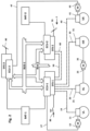
- the respective system according to Fig.1 and Fig.2 comprises a first subsystem SYS-1 and a second subsystem SYS-2.
- the first subsystem SYS-1 comprises a first electronic control unit (ECU) ECU-1 and the second subsystem SYS-2 comprises a second electronic control unit ECU-2.
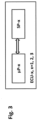
- Each of the two control units ECU-1 and ECU-2 comprises at least one microprocessor ⁇ P and at least one memory device SP, as in Fig.3
- the respective memory device SP for example a semiconductor memory, contains program code for execution by the respective microprocessor ⁇ P.
- a first accumulator BAT-1 and a second accumulator BAT-2 are used to supply electrical energy to the two subsystems SYS-1 and SYS-2, including the two electronic control units ECU-1 and ECU-2.
- the first electronic control unit ECU-1 and, if applicable, other components of the first subsystem SYS-1 are operated (at least) on the first accumulator BAT-1; the second electronic control unit ECU-2 and, if applicable, other components of the second subsystem SYS-2 are operated (at least) on the second accumulator BAT-2.
- the overall system has a high level of operational reliability, since if the first accumulator BAT-1 is faulty, (at least) the second electronic control unit ECU-2 (and, if applicable, the entire second subsystem SYS-2) can continue to operate. Likewise, if the second accumulator BAT-2 is faulty, (at least) the first electronic control unit ECU-1 (and, if applicable, the entire first subsystem SYS-1) can continue to operate.
- a first bus system BUS-1 and a second bus system BUS-2 are provided for communication (e.g. for data transfers, transmission of control commands, etc.) between the two subsystems SYS-1 and SYS-2 and in particular between the two electronic control units ECU-1 and ECU-2.
- the two bus systems BUS-1 and BUS-2 are arranged in parallel in a redundant manner with respect to the two subsystems SYS-1 and SYS-2 (in particular with respect to the two electronic control units ECU-1 and ECU-2).
- communication can be maintained using the other bus system BUS-2 or BUS-1. Since vehicles are already equipped with bus systems today, e.g. a CAN bus (Controller Area Network), these can be used for at least one of the two bus systems BUS-1 and BUS-2 in order to save additional effort.
- a CAN bus Controller Area Network
- Hydraulically actuated wheel brakes 11, 21, 31 and 41 of the vehicle are connected to the first subsystem SYS-1, more precisely to a hydraulic control unit (HCU) thereof, via hydraulic lines 10, 20, 30 and 40.
- the first subsystem SYS-1 is an electrohydraulic system that enables the brake pressures in the wheel brakes 11, 21, 31 and 41 to be generated and regulated individually, independent of the driver.
- the first subsystem SYS-1 can therefore be or include a control system, for example an anti-lock braking and/or driving dynamics control system (ABS or Electronic Stability Control, ESC) that is standard in vehicles today.
- ABS anti-lock braking and/or driving dynamics control system
- ESC Electronic Stability Control
- the first subsystem SYS-1 can generate and adjust brake pressures in one or more of the wheel brakes 11, 21, 31 and 41 independently of the second subsystem SYS-2. It is therefore possible in certain design variants for automatic braking, in particular the ACC and ESC functions, to be carried out independently by the first subsystem SYS-1.
- a further aspect in this context is that in this case hydraulic actuation of the wheel brakes 11, 21, 31 and 41 is ensured even despite a faulty second subsystem SYS-2 or despite faulty hydraulic lines 50, 60, which increases the operational reliability of the braking system.
- the brake system shown is equipped with an EPB system for the function of a parking brake (also called a handbrake) in order to be able to keep the vehicle safely stationary in EPB mode.
- the EPB system comprises a first electrical, preferably electromechanical actuating unit 13 and a second electrical, preferably electromechanical actuating unit 43.
- the first actuating unit 13 acts on the wheel brake 11 assigned to the front wheel VL and the second actuating unit 43 acts on the wheel brake 41 assigned to the front wheel VR.
- the EPB system itself does not comprise its own electronic control unit (i.e.
- the first actuating unit 13 can be controlled via a control line 17 by the electronic control unit ECU-1 of the first subsystem SYS-1 and the second actuating unit 43 can be controlled via a control line 47 by the electronic control unit ECU-2 of the second subsystem SYS-2.
- the corresponding program code for operating the EPB system is stored in the memory devices SP-1 and SP-2 of the first and second subsystems SYS-1 and SYS-2, respectively, and is executed by the corresponding microprocessor ⁇ P-1 and ⁇ P-2, respectively (cf. Fig.3 ).
- the EPB system comprises an actuating element 80 (e.g. a switch or button) as an input device, via which the driver enters his control command.
- the control command - typically "apply parking brake” or “open parking brake” - is recorded and evaluated by the first electronic control unit ECU-1. According to the result of the evaluation, the first actuating unit 13 of the wheel brake 11 assigned to the front wheel VL is actuated. Since the actuation of the second actuating unit 43 of the wheel brake 41 assigned to the front wheel VR according to Fig.1 by the second electronic control unit ECU-2, the control command is transmitted from the first electronic control unit ECU-1 to the second electronic control unit ECU-2 via the first bus system BUS-1 and/or the second bus system BUS-2. Due to the parallel bus systems BUS-1 and BUS-2, there is redundancy, so that fault-tolerant communication between the electronic control units ECU-1 and ECU-2 is guaranteed.
- the EPB system in particular the parking brake actuating units 13, 43 independently of the actuation of the control element 80, i.e. independently of the driver's control request.
- the EPB system can carry out braking or emergency braking independently, in particular as a fallback level, for example in AD or RCP mode.
- the two bus systems BUS-1 and BUS-2 can be used to connect the subsystems SYS-1 and SYS-2 with other vehicle systems, for example a Fig.1 and Fig. 2 shown third subsystem SYS-3.
- the third subsystem SYS-3 comprises a third electronic control unit ECU-3 (with associated microprocessor ⁇ P-3 and associated memory device SP-3; cf. Fig.3 ). It is operated here (at least) on the first accumulator BAT-1.
- the third subsystem SYS-3 (and in particular the third electronic control unit ECU-3) is connected, by way of example, to the first bus system BUS-1.
- the third subsystem SYS-3 is, in one embodiment, an electronically controlled automatic transmission that is operated by the driver via an input device designed as an actuating element 90 (for example a selector lever or a selector wheel).
- an actuating element 90 for example a selector lever or a selector wheel.
- actuating element 90 for example a selector lever or a selector wheel.
- additional securing of the vehicle must be provided, for which purpose a mechanical lock is provided in the transmission.
- the expense for such a mechanical transmission lock can be saved by the EPB system (in particular the parking brake actuating units 13, 43) taking over this function. This means that when the P position is selected on the actuating element 90, the parking brake is automatically closed, and when the P position is left on the actuating element 90, the parking brake is automatically opened.
- the position of the actuating element 90 is detected by the third electronic control unit ECU-3, evaluated and transmitted in parallel via the first bus system BUS-1 to the first electronic control unit ECU-1 and the second electronic control unit ECU-2, so that according to Fig.1 the first actuating unit 13 of the wheel brake 11 assigned to the front wheel VL and the second actuating unit 43 of the wheel brake 41 assigned to the front wheel VR can be actuated accordingly. Due to the redundancies described above, at least one of the two actuating units 13 and/or 43 of the EPB system can always be actuated in order to reliably guarantee the function of the transmission lock.
- the EPB system can also take on other safety functions in addition to the transmission lock function. This is the case, for example, in highly automated driving, particularly in RCP operation of the vehicle, when the vehicle can drive, steer and park without the driver being able to influence it.
- the EPB system offers an additional fallback level in the event of failures in the first subsystem SYS-1 or the second subsystem SYS-2, for example to carry out emergency braking or to be able to keep the vehicle stationary.
- the availability of the second subsystem SYS-2 is limited anyway, since the brake pedal 70 cannot be operated for emergency braking due to the driver's lack of influence. This is equivalent to a partial (mechanical) failure of the second subsystem SYS-2.
- the associated electronic control unit ECU-2 is functional in order to be able to control at least the second actuating unit 43 of the EPB system via the control line 47 in the event of a (complete) failure of the first subsystem SYS-1.
- the third subsystem SYS-3 (and in particular the third electronic control unit ECU-3) is not only connected to one of the bus systems BUS-1 or BUS 2, but in parallel to both bus systems BUS-1 and BUS-2 in order to ensure redundant communication with the electronic control units ECU-1 and ECU-2.
- one of the actuators 13 or 43 of the EPB system is directly controlled by the electronic control unit ECU-3 of the third subsystem SYS-3.
- the second actuator 43 of the EPB system is controlled via the control line 47 by the electronic control unit ECU-3 of the third subsystem SYS-3.
- a significant advantage of the motor vehicle system according to Fig.2 is that in the event of (e.g. simultaneous) failures of the first subsystem SYS-1 and the second subsystem SYS-2, the EPB system offers a further fallback level in the form of the third subsystem SYS-3, for example to carry out emergency braking or to be able to hold the vehicle at a standstill.
- the two actuators 13 and 43 of the EPB system act on the front wheels VL and VR of the vehicle, as these can transmit a considerably larger proportion of braking force than the rear wheels of the vehicle due to the dynamic axle load distribution.
- the two actuators 13 and 43 could also act on the rear wheels HL and HR of the vehicle.
- each comprise at least one microprocessor ⁇ P and at least one memory device SP.
- the respective memory device SP contains program code for execution by the respective microprocessor ⁇ P in connection with the respective desired function (e.g. EPB, transmission lock, BBW service braking, EBB, RCP, etc.).
- a single control unit ECU-1 to ECU-3 can also combine two or more of these functions in order to reduce the number of control units required in the vehicle and the associated costs.
- Each of the electronic control units ECU-1 to ECU-3 can form an independent assembly.
- Each of the electronic control units ECU-1 to ECU-3 can have its own housing with its own connections.
- the electronic control units ECU-1 to ECU-3 can also be installed in different places in the vehicle.
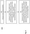
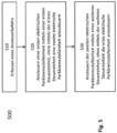
- FIGS. 4 and 5 illustrate in flow chart 400, 500 two examples of methods for controlling a motor vehicle system according to the present disclosure.
- the respective method can be derived from the Figs. 1 and 2 systems shown or a system configured differently.
- a control command is detected.
- the control command can be from one of the control units ECU-1 to ECU-3 or several of these control units ECU-1 to ECU-3.
- the control command is a parking brake command from the driver (for example, actuation of the actuating element 80).
- it is a transmission lock command from the driver (for example, in a transmission lock mode due to actuation of the actuating element 90).
- the control command can be an emergency brake command.
- the emergency brake command can be generated by the system, for example, if a brake system component fails.
- the first parking brake actuating unit 13 and the second parking brake actuating unit 43 are actuated in steps 420 and 430.
- the two parking brake actuating units 13, 43 can be actuated simultaneously or successively.
- a first of the control units ECU-1 or ECU-2 can actuate the parking brake actuating unit assigned to it and at the same time send a control command via the bus system to the second of the control units ECU-1 or ECU-2 so that it acts on the parking brake actuating unit assigned to it.
- the first electric parking brake actuating unit 13 is controlled by means of the first control unit ECU-1.
- the first control unit ECU-1 also allows the anti-lock braking and/or driving dynamics control of the subsystem SYS-1 to be controlled.
- the second electric parking brake actuating unit 43 is controlled by means of the second control unit ECU-2 (see. Fig.1 ).
- this additional control unit ECU-2 also allows the electrical brake force generator to be controlled within the SYS-2 subsystem.
- a separate parking brake control unit can be omitted.
- the system costs can be reduced in this way.
- the ability to control the two parking brake actuating devices 13, 43 using different control units ECU-1 or ECU-2 provides redundancy in that even if one of the control units ECU-1 or ECU-2 fails, at least one of the parking brake actuating units 13, 43 can still be controlled by the remaining control unit ECU-1 or ECU-2.
- Step 510 corresponds to step 410 already explained above.
- the first electric parking brake actuating unit 13 is then controlled by the first control unit ECU-1 in step 520, and the second electric parking brake actuating unit 43 is controlled by a second control unit ECU-2.
- the two control steps 520, 530 can be carried out in parallel or one after the other.
- the first control unit ECU-1 can cause the second control unit ECU-2 to control the parking brake actuating unit 43.
- the parking brake actuating unit 13 is controlled in step 520 in such a way that the control unit ECU-1 does not control the parking brake actuating unit 43. In the same way, when the parking brake actuating unit 43 is controlled, the further control unit ECU-2 does not control the other parking brake actuating unit 13.
- control units ECU-1 and ECU-2 each control only one of the two parking brake actuating units 13, 43, the control units can be made more compact.
- each of these control units ECU-1 to ECU-2 requires control components (e.g. power electronics, H-bridge, etc.) for only one parking brake actuating unit 13, 43. This saves installation space and also reduces the thermal load on the respective control units ECU-1 to ECU-2.
- control components e.g. power electronics, H-bridge, etc.
Landscapes
- Engineering & Computer Science (AREA)
- Mechanical Engineering (AREA)
- Transportation (AREA)
- General Engineering & Computer Science (AREA)
- Regulating Braking Force (AREA)
- Valves And Accessory Devices For Braking Systems (AREA)
- Braking Systems And Boosters (AREA)
Applications Claiming Priority (2)
| Application Number | Priority Date | Filing Date | Title |
|---|---|---|---|
| DE102016012530.6A DE102016012530A1 (de) | 2016-10-20 | 2016-10-20 | System mit getrennten Steuereinheiten für die Stelleinheiten einer elektrischen Parkbremse |
| PCT/EP2017/075728 WO2018073038A1 (de) | 2016-10-20 | 2017-10-10 | System mit getrennten steuereinheiten für die stelleinheiten einer elektrischen parkbremse |
Publications (3)
| Publication Number | Publication Date |
|---|---|
| EP3529117A1 EP3529117A1 (de) | 2019-08-28 |
| EP3529117B1 EP3529117B1 (de) | 2020-12-02 |
| EP3529117B2 true EP3529117B2 (de) | 2024-04-17 |
Family
ID=60080796
Family Applications (1)
| Application Number | Title | Priority Date | Filing Date |
|---|---|---|---|
| EP17783461.1A Active EP3529117B2 (de) | 2016-10-20 | 2017-10-10 | System mit getrennten steuereinheiten für die stelleinheiten einer elektrischen parkbremse |
Country Status (5)
| Country | Link |
|---|---|
| US (1) | US11046289B2 (zh) |
| EP (1) | EP3529117B2 (zh) |
| CN (1) | CN109843673B (zh) |
| DE (1) | DE102016012530A1 (zh) |
| WO (1) | WO2018073038A1 (zh) |
Families Citing this family (22)
| Publication number | Priority date | Publication date | Assignee | Title |
|---|---|---|---|---|
| DE102016012617A1 (de) * | 2016-10-20 | 2018-04-26 | Lucas Automotive Gmbh | System mit getrennten Steuereinheiten für die Stelleinheiten einer elektrischen Parkbremse |
| CN110536817B (zh) * | 2017-03-31 | 2022-06-03 | 日立安斯泰莫株式会社 | 车辆用制动系统 |
| DE102017209738A1 (de) * | 2017-06-09 | 2018-12-13 | Robert Bosch Gmbh | Kommunikationssystem für ein hydraulisches Bremssystem |
| DE102018215700A1 (de) * | 2018-09-14 | 2020-03-19 | Robert Bosch Gmbh | Vorrichtung und Verfahren zum Betreiben einer elektrischen Parkbremse eines Fahrzeugs |
| KR20200132123A (ko) * | 2019-05-15 | 2020-11-25 | 현대자동차주식회사 | 주차제동력 연계식 수동변속 차량 원격시동방법 및 원격시동 시스템 |
| DE102019207517A1 (de) | 2019-05-22 | 2020-11-26 | Volkswagen Aktiengesellschaft | Bremssteuersystem |
| US20220340113A1 (en) * | 2019-06-07 | 2022-10-27 | Mando Corporation | Electronic control unit structure of brake system |
| DE102019129305A1 (de) * | 2019-10-30 | 2021-05-06 | Knorr-Bremse Systeme für Nutzfahrzeuge GmbH | Schaltvorrichtung für ein Bremssystem für ein Fahrzeug, Bremssystem mit einer Schaltvorrichtung und Verfahren zum Betreiben einer Schaltvorrichtung |
| US11305747B1 (en) * | 2019-11-27 | 2022-04-19 | Zoox, Inc. | Control for brake system of vehicle |
| CN114761292A (zh) * | 2019-12-10 | 2022-07-15 | 沃尔沃卡车集团 | 冗余制动装置系统 |
| DE102020202919A1 (de) * | 2020-03-06 | 2021-09-09 | Continental Teves Ag & Co. Ohg | Bremsanlage mit redundanter Parkbremsenansteuerung |
| DE102020202920A1 (de) * | 2020-03-06 | 2021-09-09 | Continental Teves Ag & Co. Ohg | Bremsanlage mit redundanter Parkbremsfunktion |
| KR20210151296A (ko) * | 2020-06-04 | 2021-12-14 | 현대모비스 주식회사 | 차량의 제동장치 및 방법 |
| CN111532251A (zh) * | 2020-06-12 | 2020-08-14 | 浙江力邦合信智能制动系统股份有限公司 | 应用于无人驾驶车辆的制动系统 |
| US11465636B2 (en) * | 2021-02-01 | 2022-10-11 | Ree Automotive Ltd. | Control systems for vehicle corner modules and methods of operation |
| WO2022165636A1 (zh) * | 2021-02-02 | 2022-08-11 | 智马达汽车有限公司 | 一种冗余电子驻车制动系统、控制方法及车辆 |
| KR102603347B1 (ko) * | 2021-06-11 | 2023-11-17 | 현대모비스 주식회사 | 전자식 주차 브레이크 제어장치 및 방법 |
| CN113401095A (zh) * | 2021-06-15 | 2021-09-17 | 中汽创智科技有限公司 | 一种电子驻车系统、驻车方法、装置及终端 |
| DE102021208373A1 (de) * | 2021-08-03 | 2023-02-09 | Zf Friedrichshafen Ag | Realisierung eines ausfallsicheren Brake by Wire Systems mittels Zonensteuergeräten |
| DE102021209799A1 (de) | 2021-09-06 | 2023-03-09 | Volkswagen Aktiengesellschaft | Steuerungssystem für eine elektromechanische Aktivierung einer Bremswirkung bei einem Fahrzeug, Fahrzeug, Verfahren sowie Computerprogrammprodukt |
| DE102021209798A1 (de) | 2021-09-06 | 2023-03-09 | Volkswagen Aktiengesellschaft | Steuerungssystem für eine elektromechanische Aktivierung einer Bremswirkung bei einem Fahrzeug sowie Fahrzeug |
| US20240075817A1 (en) * | 2022-09-07 | 2024-03-07 | Harbinger Motors Inc. | Commercial electric vehicle braking systems |
Citations (3)
| Publication number | Priority date | Publication date | Assignee | Title |
|---|---|---|---|---|
| DE102011084534A1 (de) † | 2010-10-18 | 2012-04-19 | Continental Teves Ag & Co. Ohg | Fehlersichere Parkbremse für Kraftfahrzeuge |
| DE102012010562A1 (de) † | 2012-05-26 | 2013-11-28 | Audi Ag | Feststellbremsensystem für ein Fahrzeug |
| DE102014002817A1 (de) † | 2014-02-26 | 2015-09-10 | Audi Ag | Verfahren und Vorrichtung zur Betätigung einer Bremseinrichtung eines ein Automatikgetriebe aufweisenden Antriebsstranges eines Fahrzeugs, insbesondere eines Kraftfahrzeugs |
Family Cites Families (18)
| Publication number | Priority date | Publication date | Assignee | Title |
|---|---|---|---|---|
| DE19548392C2 (de) * | 1995-12-22 | 2001-05-17 | Siemens Ag | Bremsanlage für ein Kraftfahrzeug |
| DE19732168C2 (de) | 1997-07-25 | 2003-06-18 | Lucas Ind Plc | Hydraulische Fahrzeugbremse mit Feststelleinrichtung und Verfahren zum Betreiben derselben |
| DE19751431A1 (de) | 1997-11-20 | 1999-07-15 | Itt Mfg Enterprises Inc | Elektromechanische Feststellbremse |
| JP2001523619A (ja) * | 1997-11-22 | 2001-11-27 | コンティネンタル・テーベス・アクチエンゲゼルシヤフト・ウント・コンパニー・オッフェネ・ハンデルスゲゼルシヤフト | 電気機械式ブレーキ装置 |
| WO1999026820A1 (de) | 1997-11-22 | 1999-06-03 | Continental Teves Ag & Co. Ohg | Elektromechanisches bremssystem |
| JP4447771B2 (ja) * | 1997-12-23 | 2010-04-07 | ルーク ラメレン ウント クツプルングスバウ ベタイリグングス コマンディートゲゼルシャフト | 伝動装置 |
| DE19861144C2 (de) | 1998-06-12 | 2003-10-09 | Bosch Gmbh Robert | Elektrisches Bremssystem für ein Kraftfahrzeug |
| US6249758B1 (en) | 1998-06-30 | 2001-06-19 | Nortel Networks Limited | Apparatus and method for coding speech signals by making use of voice/unvoiced characteristics of the speech signals |
| DE102004059546A1 (de) | 2004-12-09 | 2006-06-22 | Lucas Automotive Gmbh | Elektronisches System zum Betreiben einer elektromechanischen Feststell-Bremsanlage |
| DE102007029910A1 (de) | 2007-02-28 | 2008-09-04 | Robert Bosch Gmbh | Elektrische Parkbremse |
| EP2183133A1 (de) | 2007-07-26 | 2010-05-12 | Continental Teves AG & Co. oHG | Feststellbremsanlage und verfahren zum betreiben einer solchen |
| DE102007059684A1 (de) | 2007-12-12 | 2009-06-25 | Lucas Automotive Gmbh | Elektronisches System zum Betreiben einer elektromechanischen Parkbremse |
| GB0802212D0 (en) | 2008-02-06 | 2008-03-12 | Meritor Heavy Vehicle Braking | A brake system and method |
| CN201998976U (zh) * | 2011-01-24 | 2011-10-05 | 比亚迪股份有限公司 | 一种电子驻车制动系统 |
| JP5673639B2 (ja) * | 2012-03-22 | 2015-02-18 | 株式会社アドヴィックス | 電動駐車ブレーキ制御装置 |
| US9751534B2 (en) * | 2013-03-15 | 2017-09-05 | Honda Motor Co., Ltd. | System and method for responding to driver state |
| DE102015203737B4 (de) * | 2015-03-03 | 2019-05-02 | Ford Global Technologies, Llc | Bremssystem und Verfahren zum Betreiben eines Bremssystems |
| US10293799B2 (en) * | 2016-07-29 | 2019-05-21 | Ford Global Technologies, Llc | Methods for transitioning into reduced braking performance modes upon failure of a primary braking system |
-
2016
- 2016-10-20 DE DE102016012530.6A patent/DE102016012530A1/de active Pending
-
2017
- 2017-10-10 EP EP17783461.1A patent/EP3529117B2/de active Active
- 2017-10-10 CN CN201780064082.8A patent/CN109843673B/zh active Active
- 2017-10-10 US US16/343,016 patent/US11046289B2/en active Active
- 2017-10-10 WO PCT/EP2017/075728 patent/WO2018073038A1/de unknown
Patent Citations (3)
| Publication number | Priority date | Publication date | Assignee | Title |
|---|---|---|---|---|
| DE102011084534A1 (de) † | 2010-10-18 | 2012-04-19 | Continental Teves Ag & Co. Ohg | Fehlersichere Parkbremse für Kraftfahrzeuge |
| DE102012010562A1 (de) † | 2012-05-26 | 2013-11-28 | Audi Ag | Feststellbremsensystem für ein Fahrzeug |
| DE102014002817A1 (de) † | 2014-02-26 | 2015-09-10 | Audi Ag | Verfahren und Vorrichtung zur Betätigung einer Bremseinrichtung eines ein Automatikgetriebe aufweisenden Antriebsstranges eines Fahrzeugs, insbesondere eines Kraftfahrzeugs |
Also Published As
| Publication number | Publication date |
|---|---|
| DE102016012530A1 (de) | 2018-04-26 |
| WO2018073038A1 (de) | 2018-04-26 |
| US11046289B2 (en) | 2021-06-29 |
| US20200070788A1 (en) | 2020-03-05 |
| EP3529117B1 (de) | 2020-12-02 |
| EP3529117A1 (de) | 2019-08-28 |
| CN109843673B (zh) | 2021-08-10 |
| CN109843673A (zh) | 2019-06-04 |
Similar Documents
| Publication | Publication Date | Title |
|---|---|---|
| EP3529117B2 (de) | System mit getrennten steuereinheiten für die stelleinheiten einer elektrischen parkbremse | |
| EP3529118B1 (de) | System mit getrennten steuereinheiten für die stelleinheiten einer elektrischen parkbremse | |
| EP3562719B1 (de) | Kraftfahrzeug-steuergerät für eine elektrische parkbremse | |
| EP2229302B1 (de) | Bremsanlage für ein fahrzeug sowie bremspedaleinrichtung für eine derartige bremsanlage | |
| DE10036287B4 (de) | Verfahren und Vorrichtung zur Steuerung von Radbremsen | |
| EP2342110B1 (de) | Kombinierte fahrzeugbremsanlage mit hydraulisch und elektromechanisch betätigbaren radbremsen | |
| EP0780276B1 (de) | Bremsanlage für ein Kraftfahrzeug | |
| DE102011110892B4 (de) | Fahrzeug-Bremssystem, sowie Verfahren hierfür | |
| EP3317149B1 (de) | Elektrische bremseinrichtung mit vom betriebsbremsbetätigungsorgan betätigbarer feststellbremse | |
| WO2018188900A1 (de) | Hydraulische kraftfahrzeug-bremsanlagen und ein steuergerätesystem hierfür, sowie verfahren zum betreiben von hydraulischen kraftfahrzeugbremsanlagen und computerprogramm zur durchführung der verfahren | |
| WO2018188901A1 (de) | Hydraulische kraftfahrzeug-bremsanlage und steuergerätesystem hierfür | |
| DE10010735A1 (de) | Elektronisch regelbares Bremsbetätigungssystem und Verfahren zur elektronisch regelbaren Bremsbetätigung für Fahrzeuge | |
| EP3642089A1 (de) | Elektrische ausrüstung eines fahrzeugs oder einer fahrzeugkombination aus einem zugfahrzeug und wenigstens einem anhängerfahrzeug | |
| DE102012216590A1 (de) | Verfahren zum Sicherstellen einer Bremswirkung | |
| DE102017011611A1 (de) | Elektrische Ausrüstung eines Fahrzeugs mit redundanter ABS- und Fahrerdynamikregelung | |
| DE102019219793A1 (de) | Hydraulische Kraftfahrzeug-Bremsanlage, Verfahren zum Betreiben derselben und Steuergerät hierfür | |
| EP1633614A2 (de) | Optimierte steuergerät-konfiguration für eine kfz-feststellbremse | |
| DE102017008948A1 (de) | Kraftfahrzeug-Bremsanlage, Verfahren zum Betreiben derselben und Steuergerät hierfür | |
| WO2019129534A1 (de) | Signalverarbeitungsvorrichtung für ein fahrzeug mit einer antiblockier-einrichtung, fahrzeug, signalverarbeitungsverfahren für ein fahrzeug, computerprogramm und steuergerät | |
| EP3380376B1 (de) | Verfahren und vorrichtung zum betreiben eines bremssystems für ein fahrzeug und bremssystem | |
| EP4347336A1 (de) | Elektro-pneumatische ausrüstung eines fahrzeugs mit vorsorglich mit backup-druck versorgtem autonomen bremskreis | |
| DE10348392B4 (de) | Sicherheitsoptimiertes Fahrzeugbremssystem mit elektrischer Parkbremsanlage | |
| WO2024094471A1 (de) | Elektro-pneumatische baueinheit und elektro-pneumatische bremseinrichtung mit doppelter redundanz und bremsschlupfregelung | |
| WO2023174494A1 (de) | Verfahren zur steuerung eines hydraulischen bremssystems und bremssystem | |
| DE102022213114A1 (de) | Verfahren und Vorrichtung zur Betätigung eines Bremssystems |
Legal Events
| Date | Code | Title | Description |
|---|---|---|---|
| STAA | Information on the status of an ep patent application or granted ep patent |
Free format text: STATUS: UNKNOWN |
|
| STAA | Information on the status of an ep patent application or granted ep patent |
Free format text: STATUS: THE INTERNATIONAL PUBLICATION HAS BEEN MADE |
|
| PUAI | Public reference made under article 153(3) epc to a published international application that has entered the european phase |
Free format text: ORIGINAL CODE: 0009012 |
|
| STAA | Information on the status of an ep patent application or granted ep patent |
Free format text: STATUS: REQUEST FOR EXAMINATION WAS MADE |
|
| 17P | Request for examination filed |
Effective date: 20190416 |
|
| AK | Designated contracting states |
Kind code of ref document: A1 Designated state(s): AL AT BE BG CH CY CZ DE DK EE ES FI FR GB GR HR HU IE IS IT LI LT LU LV MC MK MT NL NO PL PT RO RS SE SI SK SM TR |
|
| AX | Request for extension of the european patent |
Extension state: BA ME |
|
| RIN1 | Information on inventor provided before grant (corrected) |
Inventor name: FUCHS, MATTHIAS Inventor name: OHLIG, BENEDIKT Inventor name: MICHELS, ERWIN |
|
| DAV | Request for validation of the european patent (deleted) | ||
| DAX | Request for extension of the european patent (deleted) | ||
| GRAP | Despatch of communication of intention to grant a patent |
Free format text: ORIGINAL CODE: EPIDOSNIGR1 |
|
| STAA | Information on the status of an ep patent application or granted ep patent |
Free format text: STATUS: GRANT OF PATENT IS INTENDED |
|
| INTG | Intention to grant announced |
Effective date: 20200515 |
|
| RAP1 | Party data changed (applicant data changed or rights of an application transferred) |
Owner name: ZF ACTIVE SAFETY GMBH |
|
| GRAS | Grant fee paid |
Free format text: ORIGINAL CODE: EPIDOSNIGR3 |
|
| GRAA | (expected) grant |
Free format text: ORIGINAL CODE: 0009210 |
|
| STAA | Information on the status of an ep patent application or granted ep patent |
Free format text: STATUS: THE PATENT HAS BEEN GRANTED |
|
| AK | Designated contracting states |
Kind code of ref document: B1 Designated state(s): AL AT BE BG CH CY CZ DE DK EE ES FI FR GB GR HR HU IE IS IT LI LT LU LV MC MK MT NL NO PL PT RO RS SE SI SK SM TR |
|
| REG | Reference to a national code |
Ref country code: GB Ref legal event code: FG4D Free format text: NOT ENGLISH |
|
| REG | Reference to a national code |
Ref country code: AT Ref legal event code: REF Ref document number: 1340595 Country of ref document: AT Kind code of ref document: T Effective date: 20201215 Ref country code: CH Ref legal event code: EP |
|
| REG | Reference to a national code |
Ref country code: IE Ref legal event code: FG4D Free format text: LANGUAGE OF EP DOCUMENT: GERMAN |
|
| REG | Reference to a national code |
Ref country code: DE Ref legal event code: R096 Ref document number: 502017008492 Country of ref document: DE |
|
| PG25 | Lapsed in a contracting state [announced via postgrant information from national office to epo] |
Ref country code: NO Free format text: LAPSE BECAUSE OF FAILURE TO SUBMIT A TRANSLATION OF THE DESCRIPTION OR TO PAY THE FEE WITHIN THE PRESCRIBED TIME-LIMIT Effective date: 20210302 Ref country code: GR Free format text: LAPSE BECAUSE OF FAILURE TO SUBMIT A TRANSLATION OF THE DESCRIPTION OR TO PAY THE FEE WITHIN THE PRESCRIBED TIME-LIMIT Effective date: 20210303 Ref country code: FI Free format text: LAPSE BECAUSE OF FAILURE TO SUBMIT A TRANSLATION OF THE DESCRIPTION OR TO PAY THE FEE WITHIN THE PRESCRIBED TIME-LIMIT Effective date: 20201202 Ref country code: RS Free format text: LAPSE BECAUSE OF FAILURE TO SUBMIT A TRANSLATION OF THE DESCRIPTION OR TO PAY THE FEE WITHIN THE PRESCRIBED TIME-LIMIT Effective date: 20201202 |
|
| REG | Reference to a national code |
Ref country code: NL Ref legal event code: MP Effective date: 20201202 |
|
| PG25 | Lapsed in a contracting state [announced via postgrant information from national office to epo] |
Ref country code: LV Free format text: LAPSE BECAUSE OF FAILURE TO SUBMIT A TRANSLATION OF THE DESCRIPTION OR TO PAY THE FEE WITHIN THE PRESCRIBED TIME-LIMIT Effective date: 20201202 Ref country code: PL Free format text: LAPSE BECAUSE OF FAILURE TO SUBMIT A TRANSLATION OF THE DESCRIPTION OR TO PAY THE FEE WITHIN THE PRESCRIBED TIME-LIMIT Effective date: 20201202 Ref country code: SE Free format text: LAPSE BECAUSE OF FAILURE TO SUBMIT A TRANSLATION OF THE DESCRIPTION OR TO PAY THE FEE WITHIN THE PRESCRIBED TIME-LIMIT Effective date: 20201202 Ref country code: BG Free format text: LAPSE BECAUSE OF FAILURE TO SUBMIT A TRANSLATION OF THE DESCRIPTION OR TO PAY THE FEE WITHIN THE PRESCRIBED TIME-LIMIT Effective date: 20210302 |
|
| PG25 | Lapsed in a contracting state [announced via postgrant information from national office to epo] |
Ref country code: NL Free format text: LAPSE BECAUSE OF FAILURE TO SUBMIT A TRANSLATION OF THE DESCRIPTION OR TO PAY THE FEE WITHIN THE PRESCRIBED TIME-LIMIT Effective date: 20201202 Ref country code: HR Free format text: LAPSE BECAUSE OF FAILURE TO SUBMIT A TRANSLATION OF THE DESCRIPTION OR TO PAY THE FEE WITHIN THE PRESCRIBED TIME-LIMIT Effective date: 20201202 |
|
| REG | Reference to a national code |
Ref country code: LT Ref legal event code: MG9D |
|
| PG25 | Lapsed in a contracting state [announced via postgrant information from national office to epo] |
Ref country code: PT Free format text: LAPSE BECAUSE OF FAILURE TO SUBMIT A TRANSLATION OF THE DESCRIPTION OR TO PAY THE FEE WITHIN THE PRESCRIBED TIME-LIMIT Effective date: 20210405 Ref country code: SK Free format text: LAPSE BECAUSE OF FAILURE TO SUBMIT A TRANSLATION OF THE DESCRIPTION OR TO PAY THE FEE WITHIN THE PRESCRIBED TIME-LIMIT Effective date: 20201202 Ref country code: RO Free format text: LAPSE BECAUSE OF FAILURE TO SUBMIT A TRANSLATION OF THE DESCRIPTION OR TO PAY THE FEE WITHIN THE PRESCRIBED TIME-LIMIT Effective date: 20201202 Ref country code: SM Free format text: LAPSE BECAUSE OF FAILURE TO SUBMIT A TRANSLATION OF THE DESCRIPTION OR TO PAY THE FEE WITHIN THE PRESCRIBED TIME-LIMIT Effective date: 20201202 Ref country code: EE Free format text: LAPSE BECAUSE OF FAILURE TO SUBMIT A TRANSLATION OF THE DESCRIPTION OR TO PAY THE FEE WITHIN THE PRESCRIBED TIME-LIMIT Effective date: 20201202 Ref country code: CZ Free format text: LAPSE BECAUSE OF FAILURE TO SUBMIT A TRANSLATION OF THE DESCRIPTION OR TO PAY THE FEE WITHIN THE PRESCRIBED TIME-LIMIT Effective date: 20201202 Ref country code: LT Free format text: LAPSE BECAUSE OF FAILURE TO SUBMIT A TRANSLATION OF THE DESCRIPTION OR TO PAY THE FEE WITHIN THE PRESCRIBED TIME-LIMIT Effective date: 20201202 |
|
| REG | Reference to a national code |
Ref country code: DE Ref legal event code: R026 Ref document number: 502017008492 Country of ref document: DE |
|
| PLBI | Opposition filed |
Free format text: ORIGINAL CODE: 0009260 |
|
| PLAX | Notice of opposition and request to file observation + time limit sent |
Free format text: ORIGINAL CODE: EPIDOSNOBS2 |
|
| PG25 | Lapsed in a contracting state [announced via postgrant information from national office to epo] |
Ref country code: IS Free format text: LAPSE BECAUSE OF FAILURE TO SUBMIT A TRANSLATION OF THE DESCRIPTION OR TO PAY THE FEE WITHIN THE PRESCRIBED TIME-LIMIT Effective date: 20210402 |
|
| 26 | Opposition filed |
Opponent name: CONTINENTAL TEVES AG & CO. OHG Effective date: 20210830 |
|
| PG25 | Lapsed in a contracting state [announced via postgrant information from national office to epo] |
Ref country code: AL Free format text: LAPSE BECAUSE OF FAILURE TO SUBMIT A TRANSLATION OF THE DESCRIPTION OR TO PAY THE FEE WITHIN THE PRESCRIBED TIME-LIMIT Effective date: 20201202 Ref country code: IT Free format text: LAPSE BECAUSE OF FAILURE TO SUBMIT A TRANSLATION OF THE DESCRIPTION OR TO PAY THE FEE WITHIN THE PRESCRIBED TIME-LIMIT Effective date: 20201202 |
|
| PG25 | Lapsed in a contracting state [announced via postgrant information from national office to epo] |
Ref country code: DK Free format text: LAPSE BECAUSE OF FAILURE TO SUBMIT A TRANSLATION OF THE DESCRIPTION OR TO PAY THE FEE WITHIN THE PRESCRIBED TIME-LIMIT Effective date: 20201202 Ref country code: SI Free format text: LAPSE BECAUSE OF FAILURE TO SUBMIT A TRANSLATION OF THE DESCRIPTION OR TO PAY THE FEE WITHIN THE PRESCRIBED TIME-LIMIT Effective date: 20201202 |
|
| PLBB | Reply of patent proprietor to notice(s) of opposition received |
Free format text: ORIGINAL CODE: EPIDOSNOBS3 |
|
| PG25 | Lapsed in a contracting state [announced via postgrant information from national office to epo] |
Ref country code: ES Free format text: LAPSE BECAUSE OF FAILURE TO SUBMIT A TRANSLATION OF THE DESCRIPTION OR TO PAY THE FEE WITHIN THE PRESCRIBED TIME-LIMIT Effective date: 20201202 |
|
| PG25 | Lapsed in a contracting state [announced via postgrant information from national office to epo] |
Ref country code: IS Free format text: LAPSE BECAUSE OF FAILURE TO SUBMIT A TRANSLATION OF THE DESCRIPTION OR TO PAY THE FEE WITHIN THE PRESCRIBED TIME-LIMIT Effective date: 20210402 |
|
| REG | Reference to a national code |
Ref country code: CH Ref legal event code: PL |
|
| REG | Reference to a national code |
Ref country code: BE Ref legal event code: MM Effective date: 20211031 |
|
| GBPC | Gb: european patent ceased through non-payment of renewal fee |
Effective date: 20211010 |
|
| PG25 | Lapsed in a contracting state [announced via postgrant information from national office to epo] |
Ref country code: MC Free format text: LAPSE BECAUSE OF FAILURE TO SUBMIT A TRANSLATION OF THE DESCRIPTION OR TO PAY THE FEE WITHIN THE PRESCRIBED TIME-LIMIT Effective date: 20201202 |
|
| PG25 | Lapsed in a contracting state [announced via postgrant information from national office to epo] |
Ref country code: LU Free format text: LAPSE BECAUSE OF NON-PAYMENT OF DUE FEES Effective date: 20211010 Ref country code: GB Free format text: LAPSE BECAUSE OF NON-PAYMENT OF DUE FEES Effective date: 20211010 Ref country code: BE Free format text: LAPSE BECAUSE OF NON-PAYMENT OF DUE FEES Effective date: 20211031 |
|
| PG25 | Lapsed in a contracting state [announced via postgrant information from national office to epo] |
Ref country code: LI Free format text: LAPSE BECAUSE OF NON-PAYMENT OF DUE FEES Effective date: 20211031 Ref country code: CH Free format text: LAPSE BECAUSE OF NON-PAYMENT OF DUE FEES Effective date: 20211031 |
|
| PG25 | Lapsed in a contracting state [announced via postgrant information from national office to epo] |
Ref country code: FR Free format text: LAPSE BECAUSE OF NON-PAYMENT OF DUE FEES Effective date: 20211031 |
|
| PLAB | Opposition data, opponent's data or that of the opponent's representative modified |
Free format text: ORIGINAL CODE: 0009299OPPO |
|
| PG25 | Lapsed in a contracting state [announced via postgrant information from national office to epo] |
Ref country code: IE Free format text: LAPSE BECAUSE OF NON-PAYMENT OF DUE FEES Effective date: 20211010 |
|
| R26 | Opposition filed (corrected) |
Opponent name: CONTINENTAL AUTOMOTIVE TECHNOLOGIES GMBH Effective date: 20210830 |
|
| PG25 | Lapsed in a contracting state [announced via postgrant information from national office to epo] |
Ref country code: CY Free format text: LAPSE BECAUSE OF FAILURE TO SUBMIT A TRANSLATION OF THE DESCRIPTION OR TO PAY THE FEE WITHIN THE PRESCRIBED TIME-LIMIT Effective date: 20201202 |
|
| P01 | Opt-out of the competence of the unified patent court (upc) registered |
Effective date: 20230528 |
|
| PG25 | Lapsed in a contracting state [announced via postgrant information from national office to epo] |
Ref country code: HU Free format text: LAPSE BECAUSE OF FAILURE TO SUBMIT A TRANSLATION OF THE DESCRIPTION OR TO PAY THE FEE WITHIN THE PRESCRIBED TIME-LIMIT; INVALID AB INITIO Effective date: 20171010 |
|
| APAH | Appeal reference modified |
Free format text: ORIGINAL CODE: EPIDOSCREFNO |
|
| APBM | Appeal reference recorded |
Free format text: ORIGINAL CODE: EPIDOSNREFNO |
|
| APBP | Date of receipt of notice of appeal recorded |
Free format text: ORIGINAL CODE: EPIDOSNNOA2O |
|
| APBU | Appeal procedure closed |
Free format text: ORIGINAL CODE: EPIDOSNNOA9O |
|
| REG | Reference to a national code |
Ref country code: AT Ref legal event code: MM01 Ref document number: 1340595 Country of ref document: AT Kind code of ref document: T Effective date: 20221010 |
|
| PG25 | Lapsed in a contracting state [announced via postgrant information from national office to epo] |
Ref country code: AT Free format text: LAPSE BECAUSE OF NON-PAYMENT OF DUE FEES Effective date: 20221010 |
|
| PGFP | Annual fee paid to national office [announced via postgrant information from national office to epo] |
Ref country code: DE Payment date: 20230830 Year of fee payment: 7 |
|
| PUAH | Patent maintained in amended form |
Free format text: ORIGINAL CODE: 0009272 |
|
| STAA | Information on the status of an ep patent application or granted ep patent |
Free format text: STATUS: PATENT MAINTAINED AS AMENDED |
|
| 27A | Patent maintained in amended form |
Effective date: 20240417 |
|
| AK | Designated contracting states |
Kind code of ref document: B2 Designated state(s): AL AT BE BG CH CY CZ DE DK EE ES FI FR GB GR HR HU IE IS IT LI LT LU LV MC MK MT NL NO PL PT RO RS SE SI SK SM TR |
|
| REG | Reference to a national code |
Ref country code: DE Ref legal event code: R102 Ref document number: 502017008492 Country of ref document: DE |
|
| PG25 | Lapsed in a contracting state [announced via postgrant information from national office to epo] |
Ref country code: MK Free format text: LAPSE BECAUSE OF FAILURE TO SUBMIT A TRANSLATION OF THE DESCRIPTION OR TO PAY THE FEE WITHIN THE PRESCRIBED TIME-LIMIT Effective date: 20201202 |