EP3528955B1 - Selbstverriegelnder aufgabetrichter - Google Patents
Selbstverriegelnder aufgabetrichter Download PDFInfo
- Publication number
- EP3528955B1 EP3528955B1 EP17790706.0A EP17790706A EP3528955B1 EP 3528955 B1 EP3528955 B1 EP 3528955B1 EP 17790706 A EP17790706 A EP 17790706A EP 3528955 B1 EP3528955 B1 EP 3528955B1
- Authority
- EP
- European Patent Office
- Prior art keywords
- rear wall
- side wall
- closure
- actuator
- charging unit
- Prior art date
- Legal status (The legal status is an assumption and is not a legal conclusion. Google has not performed a legal analysis and makes no representation as to the accuracy of the status listed.)
- Active
Links
- 239000000463 material Substances 0.000 claims description 24
- 230000005484 gravity Effects 0.000 claims description 19
- 230000001419 dependent effect Effects 0.000 claims 1
- 238000012216 screening Methods 0.000 description 6
- 238000000034 method Methods 0.000 description 4
- 230000002787 reinforcement Effects 0.000 description 2
- 239000011435 rock Substances 0.000 description 2
- 238000006073 displacement reaction Methods 0.000 description 1
- 230000000694 effects Effects 0.000 description 1
- 230000008093 supporting effect Effects 0.000 description 1
Images

Classifications
-
- B—PERFORMING OPERATIONS; TRANSPORTING
- B65—CONVEYING; PACKING; STORING; HANDLING THIN OR FILAMENTARY MATERIAL
- B65G—TRANSPORT OR STORAGE DEVICES, e.g. CONVEYORS FOR LOADING OR TIPPING, SHOP CONVEYOR SYSTEMS OR PNEUMATIC TUBE CONVEYORS
- B65G47/00—Article or material-handling devices associated with conveyors; Methods employing such devices
- B65G47/02—Devices for feeding articles or materials to conveyors
- B65G47/16—Devices for feeding articles or materials to conveyors for feeding materials in bulk
- B65G47/18—Arrangements or applications of hoppers or chutes
- B65G47/20—Arrangements or applications of hoppers or chutes the hoppers or chutes being movable
-
- B—PERFORMING OPERATIONS; TRANSPORTING
- B02—CRUSHING, PULVERISING, OR DISINTEGRATING; PREPARATORY TREATMENT OF GRAIN FOR MILLING
- B02C—CRUSHING, PULVERISING, OR DISINTEGRATING IN GENERAL; MILLING GRAIN
- B02C21/00—Disintegrating plant with or without drying of the material
- B02C21/02—Transportable disintegrating plant
- B02C21/026—Transportable disintegrating plant self-propelled
-
- B—PERFORMING OPERATIONS; TRANSPORTING
- B02—CRUSHING, PULVERISING, OR DISINTEGRATING; PREPARATORY TREATMENT OF GRAIN FOR MILLING
- B02C—CRUSHING, PULVERISING, OR DISINTEGRATING IN GENERAL; MILLING GRAIN
- B02C23/00—Auxiliary methods or auxiliary devices or accessories specially adapted for crushing or disintegrating not provided for in preceding groups or not specially adapted to apparatus covered by a single preceding group
- B02C23/02—Feeding devices
-
- B—PERFORMING OPERATIONS; TRANSPORTING
- B07—SEPARATING SOLIDS FROM SOLIDS; SORTING
- B07B—SEPARATING SOLIDS FROM SOLIDS BY SIEVING, SCREENING, SIFTING OR BY USING GAS CURRENTS; SEPARATING BY OTHER DRY METHODS APPLICABLE TO BULK MATERIAL, e.g. LOOSE ARTICLES FIT TO BE HANDLED LIKE BULK MATERIAL
- B07B1/00—Sieving, screening, sifting, or sorting solid materials using networks, gratings, grids, or the like
- B07B1/005—Transportable screening plants
-
- B—PERFORMING OPERATIONS; TRANSPORTING
- B07—SEPARATING SOLIDS FROM SOLIDS; SORTING
- B07B—SEPARATING SOLIDS FROM SOLIDS BY SIEVING, SCREENING, SIFTING OR BY USING GAS CURRENTS; SEPARATING BY OTHER DRY METHODS APPLICABLE TO BULK MATERIAL, e.g. LOOSE ARTICLES FIT TO BE HANDLED LIKE BULK MATERIAL
- B07B13/00—Grading or sorting solid materials by dry methods, not otherwise provided for; Sorting articles otherwise than by indirectly controlled devices
- B07B13/14—Details or accessories
- B07B13/16—Feed or discharge arrangements
-
- B—PERFORMING OPERATIONS; TRANSPORTING
- B65—CONVEYING; PACKING; STORING; HANDLING THIN OR FILAMENTARY MATERIAL
- B65G—TRANSPORT OR STORAGE DEVICES, e.g. CONVEYORS FOR LOADING OR TIPPING, SHOP CONVEYOR SYSTEMS OR PNEUMATIC TUBE CONVEYORS
- B65G2201/00—Indexing codes relating to handling devices, e.g. conveyors, characterised by the type of product or load being conveyed or handled
- B65G2201/04—Bulk
-
- B—PERFORMING OPERATIONS; TRANSPORTING
- B65—CONVEYING; PACKING; STORING; HANDLING THIN OR FILAMENTARY MATERIAL
- B65G—TRANSPORT OR STORAGE DEVICES, e.g. CONVEYORS FOR LOADING OR TIPPING, SHOP CONVEYOR SYSTEMS OR PNEUMATIC TUBE CONVEYORS
- B65G2812/00—Indexing codes relating to the kind or type of conveyors
- B65G2812/06—Skip or hopper conveyors
- B65G2812/0609—Constitutive elements or auxiliary devices
- B65G2812/0618—Skips, hoppers or similar containers
- B65G2812/0627—Skips, hoppers or similar containers characterised by the configuration
Definitions
- the invention relates to a feed unit of a material processing device with a feed hopper with at least one pivotably mounted side wall and with a pivotably mounted rear wall, the side wall and the rear wall being pivotable by means of actuators between a folded transport position and an unfolded working position, with at least one in the working position
- Side wall is connected to the rear wall by means of at least one releasable lock and wherein the lock can be locked or unlocked by means of a movement of the side wall or the rear wall.
- Such a feed hopper is from the EP 2949397 A1 known.
- the feed hopper is formed from two oppositely arranged side walls and a rear wall connecting the side walls at the rear. Both the side walls and the rear wall are rotatably connected to a chassis of a material processing facility. They can be swiveled between a folded transport position and an unfolded working position. When opened, the side walls and the rear wall form a feed hopper via which the material to be processed can be fed to the material processing device. In this position, the side walls are connected to the rear wall via closure elements. The adjustment of the side walls and the rear wall between the transport position and the working position takes place by means of actuators acting between the chassis and the walls.
- a linear movement is provided in addition to the rotary movement. This makes it possible to move the rear wall or the side walls linearly in their open position.
- the closure elements are designed in such a way that they interlock or loosen by means of the linear displacement of the rear wall or the side walls.
- the rear wall is first opened and raised by means of the linear adjustment. Then the side walls are opened.
- the closure elements attached to the rear wall and those attached to the side walls are in this position Closing elements on top of each other.
- the locking elements interlock.
- the side walls and the rear wall are firmly connected to one another so that they do not fall back into their transport position even if an actuator fails.
- the rear wall In order to move the feed hopper back into its transport position, the rear wall is first lifted and the side walls folded down. The rear wall is then adjusted linearly downwards and then folded into its transport position.
- the disadvantage is that two actuators, for example in the form of hydraulic cylinders, are required for performing the rotary movement and the linear movement of the rear wall or, alternatively, a side wall. These are to be designed so that they can each bear the weight of the rear wall or the side wall. Correspondingly powerful and therefore expensive actuators are to be provided. Furthermore, the motion sequence of the actuators must be precisely coordinated with one another, which requires a corresponding control.
- a first actuator is provided for adjusting the rear wall and a second actuator for adjusting the side wall and that at least one deflecting member is provided which converts the movement of the first actuator into a rotary movement during a section of the movement converts the rear wall and during a further subsection into a translatory movement of the rear wall or that the deflecting member converts the movement of the second actuator during a subsection of the movement into a rotational movement of the side wall and during a further subsection into a translational movement of the side wall.
- the deflecting member makes it possible to use a single actuator to perform both the rotary movement for setting up or folding down the side wall or the rear wall and their linear movement for unlocking and locking the To effect side wall with the rear wall.
- An actuator can thus be saved compared with known, self-locking feed hoppers.
- the rotary movement and the translational movement take place within predetermined setting ranges of the actuator and are mechanically predetermined by the deflecting element. It is therefore advantageous not to have to coordinate the motion sequences of two actuators with one another by means of suitable control. This increases the reliability and intrinsic safety of the system.
- a simple, cost-effective and mechanically strong structure of the deflecting member can be achieved in that the deflecting member has a linear guide in which the rear wall or the side wall is mounted so as to be linearly movable and rotatable. If an actuator acts on the rear wall or side wall mounted in the deflecting member, a translational movement first takes place until the end of the linear guide is reached. If the actuator continues to act, the rotational movements of the rear wall or side wall then follow.
- the rotary and translational movement can be made possible by the fact that the actuator is rotatably connected to the rear wall or the side wall in such a way that a linear adjustment direction of the actuator is laterally spaced from an axis of rotation of the rear wall or the side wall and that a force component of the Actuator on the rear wall or the side wall transmitted force is aligned in the direction of the linear guide.
- the fact that the force is applied to the side of the axis of rotation creates a lever which leads to a rotary movement of the rear wall or the side wall.
- the force component acting in the direction of the linear guide leads to the linear adjustment of the rear wall or side wall.
- the rear wall is locked to the side wall by the translational movement of at least one of the two walls. If it is provided that the linear guide is aligned in its longitudinal extension in the direction of a component of the acting gravity, the side wall or rear wall is at the inoperative actuator is pressed into its lower position by gravity along the linear guide. This corresponds to the locking position.
- the side wall and the rear wall thus remain connected to one another even if an actuator fails. They cannot fall from their working position into the transport position. This significantly reduces the risk of accidents.
- the closure is formed from a closure receptacle and a closure insert and that through the translational movement of the rear wall or the side wall, the closure insert for locking the rear wall to the side wall in the direction of a component of gravity in the
- the locking insert can be inserted and raised from the locking receptacle for unlocking against the component of gravity.
- the connection between the side wall and the rear wall remains closed regardless of the failure of an actuator due to gravity.
- the linear guide is also oriented in the direction of a component of gravity.
- the closure receptacle and the closure insert are designed to be self-centering with respect to one another, in particular that the closure receptacle is designed as a hemispherical socket and the closure insert as a sphere or spherical segment or that the closure insert is designed as a cone and the closure receptacle as a conical receptacle.
- a self-locating lock is formed, which means that the side wall and the rear wall are aligned in an exact position with respect to one another, even if larger tolerances occur during locking.
- the combination of a ball or a spherical segment with the hemispherical socket represents a mechanically very robust closure. With a closure formed from a cone and a conical receptacle, very high closing forces can be generated.
- a secure engagement of the closure insert in the closure receptacle can be achieved in that the closure receptacle is assigned a guide element protruding over the closure receptacle and in that the guide element has a guide surface which is inclined to the linear movement of the closure insert and towards the closure receptacle.
- the guide element directs the lock insert to the lock receiver when it is locked.
- the force transmitted by the actuator to the side or rear wall is superimposed on gravity. Furthermore, the center of gravity can lie at a distance from the line of action predetermined by the actuator. If the center of gravity on its travel path crosses the line of action during the adjustment movement from the working position to the transport position, the rear wall or the side wall may become unstable over a small part of their adjustment movement.
- a spring element to act on the rear wall or side wall mounted in the deflecting member in such a way that a torque acting in the direction of the working position is transmitted to the rear wall or the side wall.
- the torque introduced by the spring element is preferably greater than the torque caused by the force of weight, so that in total a torque acting in the direction of the working position remains.
- a structurally simple and inexpensive solution for introducing the torque through the spring element can be provided in that the rear wall or the side wall is mounted in the linear guide by means of a guide bolt and that the spring element is coupled to the guide bolt in such a way that one in the direction of the longitudinal extension of the Linear guide directed force is transmitted to the guide bolt, which generates a torque acting around the mounting point of the actuator on the rear wall or the side wall.
- the spring element preferably acts in the direction of a component of gravity.
- the spring element brings a force on one side of the mounting point of the actuator, while the center of gravity of the side or rear wall is arranged on the opposite side of the mounting point.
- the torques caused are accordingly aligned in opposite directions.
- the rear or side wall experiences a resulting torque that acts in the direction of its working position.
- a high mechanical load-bearing capacity of the feed hopper can be achieved in that the pivotably mounted side wall is supported in its unfolded working position by means of at least one support strut and that the pivotable and linearly movable rear wall is held by the closure on the side wall or that the pivotably mounted rear wall is in its is supported in the unfolded working position by means of at least one support strut and that the pivotable and linearly movable side wall is held by the lock on the rear wall.
- the support strut preferably supports the rear or side wall against a chassis of the material processing device. In this way, high forces, such as those that occur when loading the feed unit, can be transferred to the chassis.
- the translationally and rotationally mounted rear or side wall is connected by the closure to the side or rear wall supported by the support strut and is thus fixed in its position so that it can be mechanically stressed.
- the closure is preferably designed in such a way that it can transmit high forces.
- the support strut has a U-shaped profile and that at least one of the actuators is at least partially surrounded by the support strut in the working position of the feed hopper.
- a load-bearing connection between the rear wall and the side wall can be achieved in that the closure is arranged between the ends of the rear wall and the side wall that face each other, which are at the top in the working position.
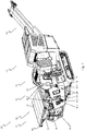
- Figure 1 shows a perspective side view of a mobile material processing device 10 with a feed unit 11 with a feed hopper 20 in its working position.
- the invention can also be used for stationary material processing devices 10.
- a subsequent pre-screening 12 Following the feed unit 11 are a subsequent pre-screening 12, a crusher 13, a drive unit 14 and a conveyor belt 15, which are fastened to a chassis 16 of the material processing device 10.
- the material processing device 10 can move independently by means of a chain drive 17.
- Two oppositely arranged side walls 21, 22 and a rear wall 23 are assigned to the feed hopper 20.
- the side walls 21, 22 and the rear wall 23 are curved towards the interior of the feed hopper 20.
- the side walls 21, 22 close off the feed hopper 20 to the side.
- the rear wall 23 closes the feed hopper 20 on the side facing away from the pre-screening 12.
- the side walls 21, 22 are each connected to the rear wall 23 by means of a lock 60.
- the feed hopper 20 is open for pre-screening 12.
- FIG. 1 shows the feeding unit 11 in its working position.
- the pivotably mounted side walls 21, 22 and the pivotably mounted rear wall 23 are folded up by means of actuators 40, 50.
- Hydraulic cylinders are provided as actuators 40, 50. They are movably attached to the chassis 16 and to the rear wall 23 or the side walls 21, 22.
- a lateral actuator counter bearing 16.2 and a rear actuator counter bearing 16.3 are arranged on the chassis 16.
- the support struts 24 are detachably mounted on lower support receptacles 16.1 which are fastened to the chassis 16.
- the support struts 24 are pivotally attached to upper support receptacles 22.3, which are each arranged on the side walls 21, 22.
- the support struts 24 are designed as U-profiles.
- the lateral second actuator 50 is covered by the U-profile of the associated support struts 24.
- the second actuator 50 is arranged to be protected from damage.
- material to be comminuted for example rock
- material processing device 10 can be fed to the material processing device 10 via the feed hopper 20 of the feed unit 11.
- the material is passed to the pre-screening 12 and from there to the crusher 13.
- the crusher 13 the material is crushed to the desired size and transported away via the conveyor belt 15.
- the individual units are driven by the drive unit 14.
- the side walls 21, 22 are supported on the chassis 16 by the support struts 24. As a result, high forces, for example when loading the feeding unit 11 with large rocks, can also be diverted to the chassis 16 without the second actuator 50 being loaded.
- the rear wall 23 is connected to the side walls 21, 22 by the closures 60, so that forces acting on the rear wall 23 are reliably intercepted and passed on to the chassis 16.
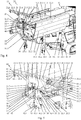
- Figure 2 shows the in Figure 1 feed hopper 20 shown in its transport position.
- the side walls 21, 22 and the rear wall 23 are folded down with the aid of the actuators 40, 50.
- the support struts 24 were detached from the lower support mounts 16.1.
- fastening eyelets 24.1 are attached at the ends of the support struts 24, through which a corresponding fastening bolt can be pushed.
- the vibration feed chute 11.1 is laterally bounded by side rails 11.2.
- the side rails 11.2 are designed in such a way that when the side walls 21, 22 are opened, they are surrounded by inlet plates 21.1, 22.1.
- the inlet plates 21.1, 22.1 are along the longitudinal sides of the vibrating feed chute 11.1 facing Side walls 21, 22 connected to these.
- the side walls 21, 22 are pivotably connected to the chassis 16.
- the mounting of the rear wall 23 enables rotational movements and linear movement.
- a correspondingly designed deflecting member is provided for this purpose.
- the deflecting member has two outer holding webs 30 and two inner holding webs 31 arranged at a distance between them.
- the holding webs 30, 31 are plate-shaped. They are aligned with the chassis 16 in the direction of the longitudinal extension of the vibratory feed chute 11.1.
- Linear guides 32 in the form of elongated holes are introduced into the holding webs 30, 31.
- the linear guides 32 are vertical and thus aligned in the direction of the acting gravity.
- Guide pins 33 are mounted in the linear guides 32.
- a guide pin 33 is guided from an outer holding web 30 to an adjacent inner holding web 31.
- one guide pin 33 is thus rotatably and linearly adjustable in the linear guides 32 of two opposing outer and inner holding webs 30, 31.
- the rear wall 23 is connected to the guide pin 33 between the outer and inner retaining webs 30, 31. This enables both a rotary and a translational movement of the rear wall 20.
- the guide pins 33 are located at the lower end of the linear guide 32.
- the guide pins 33 each have a circumferential groove 33.1.
- a tension spring is suspended in each of these. Opposite the tension springs are connected to the chassis 16 in such a way that they transmit a force acting in the direction of the longitudinal extension of the linear guides 32 and in the direction of at least one component of gravity to the guide pins 33. The tension spring thus pulls the guide pins 33 into their shown lower position of the linear guide 32.
- the rear wall 23 has a transverse termination 23.1. In the working position, this is brought directly up to the vibratory feed chute 11.1, so that no material introduced into the feed hopper 20 can fall from the vibratory feed chute 11.1 here either.
- both the total height and the total width of the material processing device 10 are significantly reduced compared to its working position. This enables the material processing device 10 to be transported on public roads.
- Figure 3 is the in Figure 2 feed hopper 20 shown with an opposite to that in Figure 2 Transport position shown linearly raised rear wall 23 is shown. This corresponds to the first movement step when moving the feed hopper 20 from its transport position into the working position. In order to reach this raised position, the first actuator 40 is extended accordingly.
- the first actuator 40 is fixed to the chassis 16 on one side so as to be rotatable about a first axis of rotation. Opposite, the first actuator 40 is mounted on the outside of the rear wall 23 so as to be rotatable about a second axis of rotation. The two axes of rotation are aligned in the same way.
- the point of application of the actuator 40 lies between the pivot axis formed by the guide bolts 33 and the center of gravity of the rear wall 23.
- the movement of the actuator 40 therefore leads to a translational movement of the rear wall 23 in its first section, which is limited by the length of the linear guide 32 .
- Figure 4 shows the in Figure 3 shown feed hopper 20 with an opened and linearly raised rear wall 23.
- the side walls 21, 22 are still in their transport position.
- outer and inner strut pairs 23.4, 23.5 are attached, preferably welded, for reinforcement.
- the edge 23.6 of the rear wall 23 facing away from the guide bolts 33 is also bent outwards for reinforcement.
- slots are made, into which the ends of the strut pairs 23.4, 23.5 are inserted.
- lifting eyes 23.3 are attached in adjacent slots and connected there to the bent edge 23.6, preferably welded.
- the first actuator 40 of the rear wall 23, designed as a hydraulic cylinder, is effective between the rear actuator counter bearing 16.3 and a rear actuator bearing 23.2.
- the rear actuator bearing 23.2 is arranged between the inner strut pairs 23.5. As already to Figure 3 executed, the axes of rotation of the rear actuator counter-bearing 16.3 and the rear actuator bearing 23.2 are aligned the same.
- the unfolded and linearly raised position of the rear wall 23 is based on the in Figure 3 Raised position shown, achieved by further extending the actuator 40.
- the guide pins 33 rest on the upper end of the linear guide 32 formed by the elongated holes.
- the further expansion of the actuator 40 thus leads to a rotary movement of the rear wall 23 about the axis of rotation formed by the guide pins 33.
- the rotational movement is preferably carried out up to a stop. In relation to the rotary movement, this corresponds to the end position of the rear wall 23.
- Figure 5 shows a section of the in Figure 4 feed hopper 20 shown with opened side walls 21, 22.
- the rear wall 23 is in its in Figure 4 shown unfolded and linearly raised position.
- the guide pins 33 lie against the upper end of the linear guide 32.
- a tension spring not shown, is stretched between the guide pins 33 and a respective spring counter bearing 16.4.
- the spring counter bearings 16.4 are attached to the chassis 16, preferably welded on.
- the tension springs are held in the grooves formed in the guide pins 33.
- the guide pins 33 are penetrated by bores 33.2 for receiving cotter pins. These set the guide pins 33 axially.
- a piston rod 41 is extended from a cylinder 42 of the actuator 40 up to the stop of the rotational and translational movement of the rear wall 23.
- a first mounting eyelet 41.1 is attached to the end of the piston rod 41.
- a first bolt 44 is guided through the first mounting eyelet 41.1 and through holes in the rear actuator bearing 23.2 that are congruent therewith.
- the first bolt 44 forms an articulated connection between the first actuator 40 and the rear wall 23.
- the first bolt 44 is axially secured by a first split pin 44.1.
- a second mounting eyelet 42.1 is attached to the cylinder 42 of the first actuator 40.
- a second bolt 45 rotatably connects the second mounting eyelet 42.1 to the rear actuator counter bearing 16.3.
- the second bolt 45 is axially fixed by a second split pin 45.1.
- a stop 43 is used on the chassis, like this Figure 3 shows. A counter-stop on the rear wall 23 strikes against this stop 43.
- a bushing 23.7 is arranged in each case between the outer strut pairs 23.4.
- the side walls 21, 22 are pivoted into their working position by the second actuators 50.
- the side walls 21, 22 are mounted on pivot bearings 22.5.
- the second actuators 50 are rotatably mounted on lateral actuator bearings 22.4 about axes of rotation aligned in the direction of the longitudinal extension of the side walls 21, 22. The linear movement of the second actuators 50 is thus shown in FIG Rotational movements of the side walls 21, 22 converted.
- a second actuator 50 preferably in the form of a hydraulic cylinder, is assigned to each side wall 21, 22.
- the support struts 24 are also pivotably connected to the upper support receptacles 22.3 by means of upper transverse bolts 24.2.
- the second actuators 50 are each shielded from the outside by the support struts 24 assigned to the U-shaped profile.
- the support struts 24 are connected to the chassis 16 opposite the upper support receptacles 22.3 via the lower support receptacles 16.1.
- the back of the side walls 21, 22 are reinforced with stiffening struts 22.6.
- the closures 60 are each formed from a closure insert 61 and a closure receptacle 62.
- the locking inserts 61 are assigned to the rear wall 23 and the locking receptacles 62 are assigned to the side walls 21, 22.
- the closure inserts 61 are arranged to the side of the bent edge 23.6.
- the edge 23.6 is not completely bent on the opposite sides of the rear wall 23.
- a foot 61.1 which carries a ball 61.2, is attached to each of the holding sections 61.3 formed in this way.
- the holding section 61.3, the foot 61.1 and the ball 61.2 are preferably welded to one another.
- the locking inserts 61 with the balls 61. 2 are aligned in the direction of the locking receptacles 62.
- a receiving socket 62.1, a guide element 62.2 and a retaining profile 62.3 are assigned to each of the locking receptacles 62.
- the holding profiles 62.3 are connected to the respective side wall 21, 22, preferably welded. They carry the receiving sockets 62.1. These are aligned open in the direction of the balls 61.2 of the locking inserts 61. Their inner contours are adapted to the outer contours of the balls 61.2.
- the guide elements 62.2 are arranged on the ends of the retaining profiles 62.3 facing away from the side walls 21, 22. They are preferably with a retaining profile 62.3 or the edge of a receiving socket 62.1 connected, in particular welded. They each form an inclined guide surface which is oriented towards the receiving socket 62.1.
- the locking inserts 61 are arranged directly above the locking receptacles 62.
- the rear wall 23 is raised so far that the locking inserts 61, in this case the balls 61.2, are guided over the upper edge of the guide elements 62.2 during a pivoting movement of the rear wall 23 into their transport position.
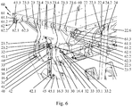
- FIG 6 shows the in Figure 5
- the feed hopper 20 is now in its final working position.
- the lock inserts 61 of the locks 60 are inserted into the lock receptacles 62 and fixed there. This creates a load-bearing connection between the side walls 21, 22 and the rear wall 23.
- the locking inserts 61 are held in the locking receptacles 62 by the weight acting on the rear wall 23.
- tension springs can also be used to secure the locking inserts 61.
- These tension springs can in particular be formed by the spring or springs described above, which are tensioned between the bolts 33 and the bearing 16.4.
- the actuator 40,50 also holds the rear / side wall 21,2 20,23 in position.
- the side walls 21, 22 are supported with respect to the chassis 16 by the support struts 24.
- the side walls 21, 22 and the rear wall 23 are therefore held securely in their working positions by the actuators 40, 50 without the necessary supporting effect.
- Material to be processed can thus be fed to the vibratory feed chute 11.1 via the work hopper 20.
- the ones in the Figures 2, 3 and 4th shown inlet plates 21.1, 22.1 of the side walls 21, 22 encompass the side rails 11.2 of the vibration feed chute 11.1.
- the closure 23.1 arranged on the rear wall 23 closes the vibration feed chute 11.1 opposite the pre-screening 12.
- the bevels 21.2, 22.2 of the side walls 21, 22 pointing towards the rear wall 23 each cover the gap between the rear wall 23 and the side walls 21, 22.
- the feed hopper Material fed in is thus almost completely fed to the vibration feed chute 11.1 and thus to the further processing process.
- the transverse movement takes place until the lock inserts 61 are fixed in the lock receptacles 62.
- the closure inserts 61 are guided in the direction of the side walls 21, 22 by the obliquely arranged guide elements 62.2.
- the side walls 21, 22 and the rear wall 23 are thus pulled tightly together by the fasteners 60.
- the guide elements 62.2 also compensate for tolerances in the positioning of the closure inserts 61 with respect to the closure receptacles 62.
- the closures 60 are designed to be self-centering due to the guide elements 62.2, the shape of the closure inserts 61 and the corresponding closure receptacles 62.
- the self-centering takes place by the balls 61.2, which are automatically guided to the lowest point of the receiving sockets 62.1 when the rear wall 23 is lowered.
- the balls 61.2 and the receiving sockets 62.1 other geometric shapes can also be provided.
- obtuse or pointed cones or bodies with other rounded, for example parabolic, outer contours can be provided as the closure insert 61 with corresponding closure receptacles 62.
- the rear wall 23 with the rear first actuator 40 is first raised. Due to the raised rear wall 23, the closures 60 between the rear wall 23 and the side walls 21, 22 are released. In the next step, the side walls 21, 22 can be moved into their positions with the aid of the second actuators 50 Figure 2 shown transport position can be folded. Before this, the support struts 24 are released from the lower support receptacles 16.1 on the chassis 16. The rear wall 23 is then lowered linearly until the guide pins 33 strike the lower end of the linear guides 32 of the deflecting member. The first actuator 40, which is pushing together further, then produces a torque which is oriented around the axis of rotation formed by the guide bolts 33. The rear wall 23 thereby pivots into its transport position.
- the illustrated embodiment shows an arrangement in which the rear wall 23 is mounted in the deflecting member so as to be movable in a translatory and rotational manner.
- the side walls 21, 22 are correspondingly mounted in deflecting members and thus can execute both the rotary and the translational movement.
- the rear wall 23 is then preferably mounted in such a way that it can only execute a pivoting movement.
- the opening and closing process of the closures then takes place analogously to the processes described, with the movement processes of the side walls 21, 22 and the rear wall 23 and the arrangement of the closure inserts 61 and closure receptacles 62 being swapped.
Description
- Die Erfindung betrifft eine Aufgabeeinheit einer Material-Verarbeitungseinrichtung mit einem Aufgabetrichter mit zumindest einer schwenkbar gelagerten Seitenwand und mit einer schwenkbar gelagerten Rückwand, wobei die Seitenwand und die Rückwand mittels Aktuatoren zwischen einer abgeklappten Transportstellung und einer aufgeklappten Arbeitsstellung schwenkbar sind, wobei in der Arbeitsstellung mindestens eine Seitenwand mit der Rückwand mittels zumindest eines lösbaren Verschlusses verbunden ist und wobei der Verschluss mittels einer Bewegung der Seitenwand oder der Rückwand verriegelbar oder entriegelbar ist.
- Ein solcher Aufgabetrichter ist aus der
EP 2949397 A1 bekannt. Der Aufgabetrichter ist aus zwei gegenüberliegend angeordneten Seitenwänden und einer die Seitenwände rückseitig verbindenden Rückwand gebildet. Sowohl die Seitenwände als auch die Rückwand sind drehbar mit einem Chassis einer Material-Verarbeitungseinrichtung verbunden. Sie können so zwischen einer abgeklappten Transportstellung und einer aufgeklappten Arbeitsstellung geschwenkt werden. Aufgeklappt bilden die Seitenwände und die Rückwand einen Aufgabetrichter aus, über den aufzubereitendes Material der Material-Verarbeitungseinrichtung zugeführt werden kann. In dieser Position sind die Seitenwände mit der Rückwand über Verschlusselemente verbunden. Die Verstellung der Seitenwände und der Rückwand zwischen der Transportstellung und der Arbeitsstellung erfolgt mittels zwischen dem Chassis und den Wänden wirkenden Aktuatoren. Für die Rückwand oder alternativ dazu für die Seitenwände ist neben der Drehbewegung eine lineare Bewegung vorgesehen. Diese ermöglicht es, die Rückwand oder die Seitenwände in ihrer aufgeklappten Stellung linear zu verschieben. Die Verschlusselemente sind so ausgeführt, dass sie mittels der linearen Verschiebung der Rückwand oder der Seitenwände ineinandergreifen oder sich lösen. Zum Verschließen des Aufgabetrichters wird beispielsweise zunächst die Rückwand aufgeklappt und mittels der linearen Verstellung angehoben. Anschließend werden die Seitenwände aufgeklappt. In dieser Stellung stehen die an der Rückwand angebrachten Verschlusselemente und die an den Seitenwänden angebrachten Verschlusselemente übereinander. Durch Absenken der Rückwand greifen die Verschlusselemente ineinander. Die Seitenwände und die Rückwand sind dadurch fest miteinander verbunden, sodass sie auch bei Ausfall eines Aktuators nicht in ihre Transportstellung zurückfallen. Um den Aufgabetrichter zurück in seine Transportstellung zu verstellen wird zunächst die Rückwand angehoben und die Seitenwände nach unten geklappt. Anschließend wird die Rückwand linear nach unten verstellt und danach in ihre Transportposition geklappt. - Nachteilig werden für die Durchführung der Drehbewegung und die Linearbewegung der Rückwand oder alternativ einer Seitenwand zwei Aktuatoren, beispielsweise in Form von Hydraulikzylindern, benötigt. Diese sind so auszulegen, dass sie jeweils das Gewicht der Rückwand bzw. der Seitenwand tragen können. Es sind entsprechend leistungsstarke und damit teure Aktuatoren vorzusehen. Weiterhin muss der Bewegungsablauf der Aktuatoren genau aufeinander abgestimmt sein, was einer entsprechenden Steuerung bedarf.
- Es ist daher Aufgabe der Erfindung, eine Aufgabeeinheit bereitzustellen, welche bei einem verringerten Bauteile- und damit Kostenbedarf einen selbstverriegelten Aufgabetrichter aufweist.
- Die Aufgabe der Erfindung wird dadurch gelöst, dass jeweils ein erster Aktuator zu Verstellung der Rückwand und ein zweiter Aktuator zur Verstellung der Seitenwand vorgesehen ist und dass zumindest ein Umlenkglied vorgesehen ist, welches die Bewegung des ersten Aktuators während eines Teilabschnitts der Bewegung in eine rotatorische Bewegung der Rückwand und während eines weiteren Teilabschnitts in eine translatorische Bewegung der Rückwand umwandelt oder dass das Umlenkglied die Bewegung des zweiten Aktuators während eines Teilabschnitts der Bewegung in eine rotatorische Bewegung der Seitenwand und während eines weiteren Teilabschnitts in eine translatorische Bewegung der Seitenwand umwandelt. Durch das Umlenkglied wird es ermöglicht, mit einem einzelnen Aktuator sowohl die Drehbewegung zum Aufstellen oder Abklappen der Seitenwand oder der Rückwand wie auch deren lineare Bewegung zum Entriegeln und zum Verriegeln der Seitenwand mit der Rückwand zu bewirken. Es kann somit gegenüber bekannten, selbstverriegelnden Aufgabetrichtern ein Aktuator eingespart werden. Die Drehbewegung und die translatorische Bewegung erfolgen innerhalb vorgegebener Stellbereiche des Aktuators und sind durch das Umlenkglied mechanisch vorgegeben. Es müssen somit vorteilhaft nicht die Bewegungsabläufe zweier Aktuatoren durch geeignete Ansteuerung aufeinander abgestimmt werden. Dadurch werden die Zuverlässigkeit und die Eigensicherheit des Systems erhöht.
- Ein einfacher, kostengünstiger und mechanisch stark belastbarer Aufbau des Umlenkglieds kann dadurch erreicht werden, dass das Umlenkglied eine Linearführung aufweist, in welcher die Rückwand oder die Seitenwand linear beweglich und drehbar gelagert ist. Wirkt ein Aktuator auf die in dem Umlenkglied gelagerte Rückwand bzw. Seitenwandein, so erfolgt zunächst eine translatorische Bewegung, bis das Ende der Linearführung erreicht ist. Bei einem weiteren Einwirken des Aktuators folgt ab dann die Rotationsbewegungen der Rückwand bzw. Seitenwand.
- Die rotatorische und die translatorische Bewegung können dadurch ermöglicht werden, dass der Aktuator derart drehbar mit der Rückwand oder der Seitenwand verbunden ist, dass eine lineare Verstellrichtung des Aktuators seitlich beabstandet zu einer Drehachse der Rückwand oder der Seitenwand ausgerichtet ist und dass eine Kraftkomponente der von dem Aktuator auf die Rückwand oder die Seitenwand übertragenen Kraft in Richtung der Linearführung ausgerichtet ist. Dadurch, dass die Krafteinwirkung seitlich der Drehachse erfolgt, ist ein Hebel gebildet, welcher zu einer Drehbewegung der Rückwand bzw. der Seitenwand führt. Die in Richtung der Linearführung wirkende Kraftkomponente führt hingegen zur linearen Verstellung der Rückwand bzw. Seitenwand.
- Die Verriegelung der Rückwand mit der Seitenwand erfolgt durch die translatorische Bewegung zumindest einer der beiden Wände. Ist es vorgesehen, dass die Linearführung in ihrer Längserstreckung in Richtung einer Komponente der wirkenden Schwerkraft ausgerichtet ist, so wird die Seitenwand bzw. Rückwand bei nicht wirkendem Aktuator durch die Schwerkraft entlang der Linearführung in ihre untere Position gedrückt. Dies entspricht der Verriegelungsposition. Die Seitenwand und die Rückwand bleiben somit auch bei Ausfall eines Aktuators miteinander verbunden. Sie können nicht von ihrer Arbeitsstellung in die Transportstellung fallen. Dadurch wird das Unfallrisiko deutlich reduziert.
- Entsprechend einer bevorzugten Ausgestaltungsvariante der Erfindung kann es vorgesehen sein, dass der Verschluss aus einer Verschlussaufnahme und einem Verschlusseinsatz gebildet ist und dass durch die translatorische Bewegung der Rückwand oder der Seitenwand der Verschlusseinsatz zum Verriegeln der Rückwand mit der Seitenwand in Richtung einer Komponente der Schwerkraft in den Verschlusseinsatz einführbar und zum Entriegeln entgegen der Komponente der Schwerkraft aus der Verschlussaufnahme anhebbar ist. Die Verbindung zwischen der Seitenwand und der Rückwand bleibt dadurch unabhängig von einem Ausfall eines Aktuators durch die Schwerkraft geschlossen. Dazu ist es vorteilhaft, wenn auch die Linearführung in Richtung einer Komponente der Schwerkraft ausgerichtet ist.
- Vorteilhaft kann es vorgesehen sein, dass die Verschlussaufnahme und der Verschlusseinsatz selbstzentrierend zueinander ausgebildet sind, insbesondere dass die Verschlussaufnahme als halbkugelförmige Pfanne und der Verschlusseinsatz als Kugel oder Kugelabschnitt ausgeführt sind oder dass der Verschlusseinsatz als Kegel und die Verschlussaufnahme als kegelförmige Aufnahme ausgebildet sind. Es wird so ein selbstfindender Verschluss gebildet, der dazu führt, dass die Seitenwand und die Rückwand auch bei größeren auftretenden Toleranzen beim Verriegeln in eine exakte Position zueinander ausgerichtet werden. Die Kombination einer Kugel bzw. eines Kugelabschnitts mit der halbkugelförmigen Pfanne stellt einen mechanisch sehr robusten Verschluss dar. Mit einem aus einem Kegel und einer kegelförmige Aufnahme gebildeten Verschluss können sehr hohe Schließkräfte erzeugt werden.
- Ein sicheres Eingreifen des Verschlusseinsatzes in die Verschlussaufnahme kann dadurch erreicht werden, dass der Verschlussaufnahme ein über die Verschlussaufnahme hervorstehendes Führungselement zugeordnet ist und dass das Führungselement eine geneigt zur Linearbewegung des Verschlusseinsatzes und zur Verschlussaufnahme hin verlaufende Führungsfläche aufweist. Das Führungselement lenkt den Verschlusseinsatz beim Verriegeln zur Verschlussaufnahme. Eine solche Ausgestaltung stellt sicher, dass der Verschlusseinsatz stets zuverlässig in die Verschlussaufnahme einfährt, insbesondere auch dann, wenn beispielsweise auf die Rückwand eine Trichtererweiterung aufgesetzt ist, die zu einer Verlagerung des Gesamtschwerpunkts führt oder wenn die Maschine schräg am Hang steht.
- Der durch den Aktuator auf die Seiten- bzw. Rückwand übertragenen Kraft ist die Schwerkraft überlagert. Weiterhin kann der Schwerpunkt beabstandet zu der durch den Aktuator vorgegebenen Wirklinie liegen. Wenn nun während der Verstellbewegung von der Arbeitsstellung in die Transportstellung der Schwerpunkt auf seinem Verfahrweg die Wirklinie kreuzt, kann es zu einer instabilen Lage der Rückwand oder der Seitenwand auf einem kleinen Teil ihrer Verstellbewegung kommen. Um ein hartes Umschlagen der Rück-/Seitenwand zu dämpfen, kann es vorgesehen sein, dass an der in dem Umlenkglied gelagerten Rückwand oder Seitenwand ein Federelement derart angreift, dass ein in Richtung der Arbeitsstellung wirkendes Drehmoment auf die Rückwand oder die Seitenwand übertragen wird. Das von dem Federelement eingebrachte Drehmoment ist bei aufgerichteter Seiten- bzw. Rückwand vorzugsweise größer als das durch die Gewichtskraft bewirkte Drehmoment, so dass in Summe ein in Richtung der Arbeitsstellung wirkendes Drehmoment verbleibt.
- Eine konstruktiv einfache und kostengünstige Lösung zum Einbringen des Drehmomentes durch das Federelement kann dadurch bereitgestellt werden, dass die Rückwand oder die Seitenwand mittels eines Führungsbolzens in der Linearführung gelagert ist und dass das Federelement an dem Führungsbolzen derart angekoppelt ist, dass eine in Richtung der Längserstreckung der Linearführung gerichtete Kraft auf den Führungsbolzen übertragen wird, welche ein um den Montagepunkt des Aktuators an der Rückwand oder der Seitenwand wirkendes Drehmoment erzeugt. Das Federelement wirkt dabei vorzugsweise in Richtung einer Komponente der Schwerkraft. Dadurch bringt das Federelement auf einer Seite des Montagepunktes des Aktuators eine Kraft ein, während der Schwerpunkt der Seiten- oder Rückwand auf der gegenüberliegenden Seite des Montagepunktes angeordnet ist. Die bewirkten Drehmomente sind entsprechend gegenläufig ausgerichtet. Durch geeignete Auslegung der Federkraft erfährt die Rück- bzw. Seitenwand ein resultierendes, in Richtung ihrer Arbeitsstellung wirkendes Drehmoment.
- Eine hohe mechanische Belastbarkeit des Aufgabetrichters kann dadurch erreicht werden, dass die schwenkbar gelagerte Seitenwand in ihrer aufgeklappten Arbeitsstellung mittels zumindest einer Stützstrebe abgestützt ist und dass die schwenkbar und linear bewegliche Rückwand durch den Verschluss an der Seitenwand gehalten ist oder dass die schwenkbar gelagerte Rückwand in ihrer aufgeklappten Arbeitsstellung mittels zumindest einer Stützstrebe abgestützt ist und dass die schwenkbar und linear bewegliche Seitenwand durch den Verschluss an der Rückwand gehalten ist. Die Stützstrebe stützt die Rück- bzw. Seitenwand vorzugsweise gegen ein Chassis der Material-Verarbeitungseinrichtung ab. Damit können hohe Kräfte, wie sie beim Bestücken der Aufgabeeinheit auftreten, an das Chassis abgeleitet werden. Die translatorisch und rotatorisch gelagerte Rück- bzw. Seitenwand ist durch den Verschluss mit der durch die Stützstrebe abgestützten Seiten- bzw. Rückwand verbunden und dadurch in ihrer Position mechanisch belastbar festgelegt. Vorzugsweise ist der Verschluss derart ausgelegt, dass er hohe Kräfte übertragen kann.
- Um den Aktuator vor Beschädigungen zu schützen kann es vorgesehen sein, dass die Stützstrebe ein U-förmiges Profil aufweist und dass in der Arbeitsstellung des Aufgabetrichters zumindest einer der Aktuatoren zumindest teilweise von der Stützstrebe umgeben ist.
- Eine belastbare Verbindung zwischen der Rückwand und der Seitenwand kann dadurch erreicht werden, dass der Verschluss zwischen den in Arbeitsstellung oberen einander zugewandten Enden der Rückwand und der Seitenwand angeordnet ist.
- Die Erfindung wird im Folgenden anhand eines in den Zeichnungen dargestellten Ausführungsbeispiels näher erläutert. Es zeigen:
- Figur 1
- in einer perspektivischen Seitenansicht eine mobile Material-Verarbeitungseinrichtung mit einer Aufgabeeinheit mit einem Aufgabetrichter in seiner Arbeitsstellung,
- Figur 2
- den in
Figur 1 gezeigten Aufgabetrichter in seiner Transportposition, - Figur 3
- den in
Figur 2 gezeigte Aufgabetrichter mit einer linear angehobenen Rückwand, - Figur 4
- den in
Figur 3 gezeigten Aufgabetrichter mit einer aufgeklappten und linear angehobenen Rückwand, - Figur 5
- einen Ausschnitt des in
Figur 4 gezeigten Aufgabetrichters mit aufgeklappten Seitenwänden und - Figur 6
- den in
Figur 5 gezeigten Ausschnitt des Aufgabetrichters mit abgesenkter Rückwand. -
Figur 1 zeigt einer perspektivischen Seitenansicht eine mobile Material-Verarbeitungseinrichtung 10 mit einer Aufgabeeinheit 11 mit einem Aufgabetrichter 20 in seiner Arbeitsstellung. Die Erfindung kann auch für stationäre Material-Verarbeitungseinrichtungen 10 verwendet werden. - Der Aufgabeeinheit 11 nachfolgend sind eine nachfolgende Vorabsiebung 12, ein Brecher 13, eine Antriebseinheit 14 und ein Förderband 15 angeordnet, welche an einem Chassis 16 der Material-Verarbeitungseinrichtung 10 befestigt sind. Die Material-Verarbeitungseinrichtung 10 kann mittels eines Kettenantriebs 17 eigenständig fahren.
- Dem Aufgabetrichter 20 sind zwei gegenüberliegend angeordnete Seitenwände 21, 22 sowie eine Rückwand 23 zugeordnet. Die Seitenwände 21, 22 und die Rückwand 23 sind zum Inneren des Aufgabetrichters 20 gewölbt ausgeführt. Dabei schließen die Seitenwände 21, 22 den Aufgabetrichter 20 zur Seite hin ab. Die Rückwand 23 schließt den Aufgabetrichter 20 auf der der Vorabsiebung 12 abgewandten Seite ab. Die Seitenwände 21, 22 sind jeweils mittels eines Verschlusses 60 mit der Rückwand 23 verbunden. Zur Vorabsiebung 12 hin ist der Aufgabetrichter 20 geöffnet.
-
Figur 1 zeigt die Aufgabeeinheit 11 in ihre Arbeitsstellung. Dabei sind die schwenkbar gelagerten Seitenwände 21, 22 und die schwenkbar gelagerte Rückwand 23 mittels Aktuatoren 40, 50 nach oben geklappt. Als Aktuatoren 40, 50 sind Hydraulikzylinder vorgesehen. Sie sind beweglich an dem Chassis 16 und an der Rückwand 23 bzw. den Seitenwänden 21, 22 befestigt. Dazu sind an dem Chassis 16 ein seitliches Aktuatorgegenlager 16.2 und ein rückseitiges Aktuatorgegenlager 16.3 angeordnet. In der Arbeitsstellung sind die Seitenwände 21, 22 durch Stützstreben 24 gegen das Chassis 16 abgestützt. Die Stützstreben 24 sind lösbar an unteren Stützenaufnahmen 16.1, welche an dem Chassis 16 befestigt sind, montiert. Gegenüberliegend sind die Stützstreben 24 schwenkbar an oberen Stützenaufnahmen 22.3, welche jeweils an den Seitenwänden 21, 22 angeordnet sind, befestigt. Vorliegend sind die Stützstreben 24 als U-Profile ausgeführt. In der Arbeitsstellung ist der seitliche zweite Aktuator 50 durch das U-Profil der zugeordneten Stützstreben 24 überdeckt. Dadurch ist der zweite Aktuator 50 vor Beschädigungen geschützt angeordnet. - In der Arbeitsstellung kann der Material-Verarbeitungseinrichtung 10 zu zerkleinerndes Material, beispielsweise Gestein, über den Aufgabetrichter 20 der Aufgabeeinheit 11 zugeführt werden. Das Material wird zu der Vorabsiebung 12 und von dort zu dem Brecher 13 geleitet. Im Brecher 13 wir das Material auf die gewünschte Größe zerkleinert und über das Förderband 15 abtransportiert. Die einzelnen Aggregate werden über die Antriebseinheit 14 angetrieben.
- Die Seitenwände 21, 22 sind durch die Stützstreben 24 an dem Chassis 16 abgestützt. Dadurch können auch hohe Kräfte, beispielsweise beim Beladen der Aufgabeeinheit 11 mit großen Gesteinsbrocken, an das Chassis 16 abgeleitet werden, ohne dass der zweite Aktuator 50 belastet wird. Die Rückwand 23 ist durch die Verschlüsse 60 mit den Seitenwänden 21, 22 verbunden, sodass auch auf die Rückwand 23 einwirkende Kräfte sicher abgefangen und an das Chassis 16 weitergeleitet werden.
-
Figur 2 zeigt den inFigur 1 gezeigten Aufgabetrichter 20 in seiner Transportposition. Die Seitenwände 21, 22 und die Rückwand 23 sind mit Hilfe der Aktuatoren 40, 50 nach unten geklappt. Dazu wurden die Stützstreben 24 von den unteren Stützenaufnahmen 16.1 gelöst. Zum Verbinden der Stützstreben 24 mit den unteren Stützenaufnahmen 16.1 sind endseitig an den Stützstreben 24 Befestigungsösen 24.1 angebracht, durch welche ein entsprechender Befestigungsbolzen geschoben werden kann. - Durch die abgeklappten Seitenwände 21, 22 und die abgeklappte Rückwand 23 ist der Blick auf eine Vibrations-Aufgaberinne 11.1 der Aufgabeeinheit 11 freigegeben. In Arbeitsstellung wird durch die Vibrations-Aufgaberinne 11.1 das der Aufgabeeinheit 11 zugeführte Material zur Vorabsiebung 12 transportiert. Die Vibrations-Aufgaberinne 11.1 ist seitlich von Seitenschienen 11.2 begrenzt. Die Seitenschienen 11.2 sind derart ausgelegt, dass sie bei aufgeklappten Seitenwänden 21, 22 von Einleitblechen 21.1, 22.1 umfasst werden. Die Einleitbleche 21.1, 22.1 sind entlang den der Vibrations-Aufgaberinne 11.1 zugewandten Längsseiten der Seitenwände 21, 22 mit diesen verbunden. Durch diese Anordnung der Einleitbleche 21.1, 22.1 und der Seitenschienen 11.2 ist sichergestellt, dass dem in Arbeitsposition verstellten Aufgabetrichter 20 zugeführtes Material auf die Vibrations-Aufgaberinne 11.1 geleitet wird und nicht seitlich davon vorbeifällt. An den der Rückwand 23 zugewandten Enden der Seitenwände 21, 22 sind abgewinkelt zu den Seitenwänden 21, 22 ausgerichtete Abkantungen 21.2, 22.2 angebracht. Diese sind in Arbeitsstellung des Aufgabetrichters 20 von innen entlang der äußeren Kanten der Rückwand 23 geführt. Sie überbrücken so jeweils einen möglichen, zwischen der Rückwand 23 und den Seitenwänden 21, 22 gebildeten Spalt. Dadurch kann auch hier kein der Aufgabeeinheit 11 zugeführtes Material aus dem Aufgabetrichter 20 fallen.
- In dem gezeigten Ausführungsbeispiel sind die Seitenwände 21, 22 schwenkbar mit dem Chassis 16 verbunden. Die Lagerung der Rückwand 23 ermöglicht eine Rotationsbewegungen und eine Linearbewegung. Dazu ist ein entsprechend ausgelegtes Umlenkglied vorgesehen. Das Umlenkglied weist vorliegend zwei äußere Haltestege 30 und zwei zwischen diesen beabstandet angeordnete innere Haltestege 31 auf. Die Haltestege 30, 31 sind plattenförmig ausgebildet. Sie sind in Richtung der Längserstreckung der Vibrations-Aufgaberinne 11.1 ausgerichtet mit dem Chassis 16 verbunden. In die Haltestege 30, 31 sind Linearführungen 32 in Form von Langlöchern eingebracht. Die Linearführungen 32 sind vertikal und damit in Richtung der wirkenden Schwerkraft ausgerichtet. In den Linearführungen 32 sind Führungsbolzen 33 gelagert. Dabei ist jeweils ein Führungsbolzen 33 von einem äußeren Haltesteg 30 zu einem benachbarten inneren Haltesteg 31 geführt. Jeweils ein Führungsbolzen 33 ist somit drehbar und linear verstellbar in den Linearführungen 32 zweier gegenüberstehender äußerer und innerer Haltestege 30, 31 gelagert. Die Rückwand 23 ist jeweils zwischen dem äußeren und dem inneren Haltesteg 30, 31 mit dem Führungsbolzen 33 verbunden. Dadurch wird sowohl eine rotatorische als auch eine translatorische Bewegung der Rückwand 20 ermöglicht. In der Transportstellung ist die Rückwand nach unten geklappt und die Führungsbolzen 33 befinden sich am unteren Ende der Linearführung 32. Seitlich neben den äußeren Haltestegen 30 weisen die Führungsbolzen 33 jeweils eine umlaufende Nut 33.1 auf.
- In diese ist jeweils eine nicht dargestellte Zugfeder eingehängt. Gegenüberliegend sind die Zugfedern mit dem Chassis 16 derart verbunden, dass sie eine in Richtung der Längserstreckung der Linearführungen 32 und in Richtung zumindest einer Komponente der Schwerkraft wirkende Kraft auf die Führungsbolzen 33 übertragen. Die Zugfeder zieht die Führungsbolzen 33 somit in ihre gezeigte untere Position der Linearführung 32.
- An ihrem inneren Ende weist die Rückwand 23 einen quer verlaufenden Abschluss 23.1 auf. In Arbeitsposition ist dieser unmittelbar an die Vibrations-Aufgaberinne 11.1 herangeführt, sodass auch hier kein in den Aufgabetrichter 20 eingeführtes Material von der Vibrations-Aufgaberinne 11.1 fallen kann.
- Durch die in ihre Transportstellung abgeklappten Seitenwände 21, 22 und Rückwand 23 sind sowohl die Gesamthöhe wie auch die Gesamtbreite der Material-Verarbeitungseinrichtung 10 gegenüber ihrer Arbeitsstellung deutlich reduziert. Dies ermöglicht einen Transport der Material-Verarbeitungseinrichtung 10 auf öffentlichen Verkehrswegen.
- In
Figur 3 ist der inFigur 2 gezeigte Aufgabetrichter 20 mit einer gegenüber der inFigur 2 gezeigten Transportstellung linear angehobenen Rückwand 23 dargestellt. Dies entspricht dem ersten Bewegungsschritt bei der Verstellung des Aufgabetrichters 20 von seiner Transportstellung in die Arbeitsstellung. Um diese angehobenen Position zu erreichen wird der erste Aktuator 40 entsprechend ausgefahren. Wie zuFigur 1 und genauer in denFiguren 4, 5 und6 gezeigt, ist der erste Aktuator 40 an einer Seite um eine erste Drehachse drehbar an dem Chassis 16 festgelegt. Gegenüberliegend ist der erste Aktuator 40 um eine zweite Drehachse drehbar an der Außenseite der Rückwand 23 gelagert. Die beiden Drehachsen sind dabei gleich ausgerichtet. Der Angriffspunkt des Aktuators 40 liegt zwischen der durch die Führungsbolzen 33 gebildeten Schwenkachse und dem Schwerpunkt der Rückwand 23. Die Bewegung des Aktuators 40 führt daher in ihrem ersten Teilabschnitt, der durch die Länge der Linearführung 32 begrenzt ist, zu einer translatorischen Bewegung der Rückwand 23. -
Figur 4 zeigt den inFigur 3 gezeigten Aufgabetrichter 20 mit einer aufgeklappten und linear angehobenen Rückwand 23. Die Seitenwände 21, 22 befinden sich weiterhin in ihrer Transportstellung. - Auf der jetzt sichtbaren Außenseite der Rückwand 23 sind zur Verstärkung äußere und innere Strebenpaare 23.4, 23.5 angebracht, vorzugsweise aufgeschweißt. Der von den Führungsbolzen 33 abgewandte Rand 23.6 der Rückwand 23 ist ebenfalls zur Verstärkung nach außen umgebogen. In den umgebogenen Rand 23.6 sind Schlitze eingebracht, in welche die Enden der Strebenpaare 23.4, 23.5 eingeführt sind. Weiterhin sind Hebeösen 23.3 in benachbarten Schlitzen angebracht und dort mit dem umgebogenen Rand 23.6 verbunden, vorzugsweise verschweißt.
- Der als Hydraulikzylinder ausgeführte erste Aktuator 40 der Rückwand 23 ist zwischen dem rückseitigen Aktuatorgegenlager 16.3 und einem rückseitigen Aktuatorlager 23.2 wirksam. Das rückseitige Aktuatorlager 23.2 ist zwischen den inneren Strebenpaaren 23.5 angeordnet. Wie bereits zu
Figur 3 ausgeführt, sind die Drehachsen des rückseitigen Aktuatorgegenlagers 16.3 und des rückseitigen Aktuatorlagers 23.2 gleich ausgerichtet. - Die aufgeklappte und linear angehobene Position der Rückwand 23 wird, ausgehend von der in
Figur 3 gezeigten angehobenen Position, durch weiteres Ausfahren des Aktuators 40 erreicht. In der inFigur 3 gezeigten angehobenen Position liegen die Führungsbolzen 33 am oberen Ende der durch die Langlöcher gebildeten Linearführung 32 an. Die weitere Expansion des Aktuators 40 führt somit zu einer Drehbewegung der Rückwand 23 um die durch die Führungsbolzen 33 gebildete Drehachse. Die rotatorische Bewegung erfolgt vorzugsweise bis zu einem Anschlag. Bezogen auf die Drehbewegung entspricht dies der Endposition der Rückwand 23. -
Figur 5 zeigt einen Ausschnitt des inFigur 4 gezeigten Aufgabetrichters 20 mit aufgeklappten Seitenwänden 21, 22. Die Rückwand 23 steht dabei in ihrer inFigur 4 gezeigten aufgeklappten und linear angehobenen Position. Die Führungsbolzen 33 liegen am oberen Ende der Linearführung 32 an. Jeweils eine nicht dargestellte Zugfeder ist zwischen den Führungsbolzen 33 und jeweils einem Federgegenlager 16.4 gespannt. Die Federgegenlager 16.4 sind am Chassis 16 befestigt, vorzugsweise angeschweißt. Die Zugfedern sind in den in die Führungsbolzen 33 eingeformten Nuten gehalten. Seitlich der Nuten sind die Führungsbolzen 33 von Bohrungen 33.2 zur Aufnahme von Sicherungssplinten durchdrungen. Diese legen die Führungsbolzen 33 axial fest. - In der angehobenen Position der Rückwand 23 ist eine Kolbenstange 41 bis zum Anschlag der rotatorischen und der translatorischen Bewegung der Rückwand 23 aus einem Zylinder 42 des Aktuators 40 ausgefahren. Am Ende der Kolbenstange 41 ist eine erste Montageöse 41.1 angebracht. Ein erster Bolzen 44 ist durch die erste Montageöse 41.1 und durch dazu in Deckung stehende Bohrungen in dem rückseitigen Aktuatorlager 23.2 geführt. Der erste Bolzen 44 bildet eine gelenkige Verbindung zwischen dem ersten Aktuator 40 und der Rückwand 23. Axial ist der erste Bolzen 44 durch einen ersten Splint 44.1 gesichert. An dem Zylinder 42 des ersten Aktuators 40 ist eine zweite Montageöse 42.1 befestigt. Ein zweiter Bolzen 45 verbindet die zweite Montageöse 42.1 drehbar mit dem rückseitigen Aktuatorgegenlager 16.3. Der zweite Bolzen 45 ist axial durch einen zweiten Splint 45.1 festgelegt.
- Zur Begrenzung der Aufrichtbewegung der Rückwand 23 ist ein Anschlag 43 am Chassis verwendet, wie dies
Figur 3 zeigt. An diesem Anschlag 43 schlägt ein Gegenanschlag der Rückwand 23 an. - Zwischen den äußeren Strebenpaaren 23.4 ist jeweils eine Buchse 23.7 angeordnet. Die Seitenwände 21, 22 sind durch die zweiten Aktuatoren 50 in ihre Arbeitsstellung geschwenkt. Dazu sind die Seitenwände 21, 22 auf Drehlagern 22.5 gelagert. Die zweiten Aktuatoren 50 sind an seitlichen Aktuatorlagern 22.4 um in Richtung der Längserstreckung der Seitenwände 21, 22 ausgerichtete Drehachsen drehbar gelagert. Die Linearbewegung der zweiten Aktuatoren 50 wird so in Drehbewegungen der Seitenwände 21, 22 umgewandelt. Jeder Seitenwand 21, 22 ist ein zweiter Aktuator 50, vorzugsweise in Form eines Hydraulikzylinders, zugeordnet. Die Stützstreben 24 sind mittels oberen Querbolzen 24.2 ebenfalls schwenkbar mit oberen Stützenaufnahmen 22.3 verbunden. In der gezeigten Arbeitsstellung der Seitenwände 21, 22 sind die zweiten Aktuatoren 50 jeweils von dem U-förmigen Profil zugeordneter Stützstreben 24 nach außen abgeschirmt. Wie zu
Figur 1 gezeigt, sind die Stützstreben 24 gegenüberliegend zu den oberen Stützenaufnahmen 22.3 über die unteren Stützenaufnahmen 16.1 mit dem Chassis 16 verbunden. Die Rückseite der Seitenwände 21, 22 sind mit Versteifungsstreben 22.6 verstärkt. Durch diesen Aufbau können hohe Kräfte, wie sie durch das in den Aufgabetrichter eingebrachte Material übertragen werden können, sicher abgefangen und an das Chassis weitergeleitet werden. - Die Verschlüsse 60 sind in dem gezeigten Ausführungsbeispiel aus jeweils einem Verschlusseinsatz 61 und einer Verschlussaufnahme 62 gebildet. Dabei sind die Verschlusseinsätze 61 der Rückwand 23 und die Verschlussaufnahmen 62 den Seitenwänden 21, 22 zugeordnet. Die Verschlusseinsätze 61 sind seitlich des umgebogenen Randes 23.6 angeordnet. Dazu ist der Rand 23.6 an den gegenüberliegenden Seiten der Rückwand 23 nicht vollständig abgebogen. An so gebildeten Halteabschnitten 61.3 ist jeweils ein Fuß 61.1, der eine Kugel 61.2 trägt, befestigt. Der Halteabschnitt 61.3, der Fuß 61.1 und die Kugel 61.2 sind vorzugsweise miteinander verschweißt. In der aufgeklappten und linear angehobenen Stellung der Rückwand 23 und der aufgeklappten Stellung der Seitenwände 21, 22 sind die Verschlusseinsätze 61 mit den Kugeln 61.2 in Richtung der Verschlussaufnahmen 62 ausgerichtet. Den Verschlussaufnahmen 62 sind jeweils eine Aufnahmepfanne 62.1, ein Führungselement 62.2 und ein Halteprofil 62.3 zugeordnet. Die Halteprofile 62.3 sind mit der jeweiligen Seitenwand 21, 22 verbunden, vorzugsweise verschweißt. Sie tragen die Aufnahmepfannen 62.1. Diese sind in Richtung der Kugeln 61.2 der Verschlusseinsätze 61 geöffnet ausgerichtet. Ihre Innenkonturen sind an die Außenkonturen der Kugeln 61.2 angepasst. Die Führungselemente 62.2 sind an den von den Seitenwänden 21, 22 abgewandten Enden der Halteprofile 62.3 angeordnet. Sie sind vorzugsweise mit einem Halteprofil 62.3 oder dem Rand einer Aufnahmepfanne 62.1 verbunden, insbesondere verschweißt. Sie bilden jeweils eine schräg verlaufende Führungsfläche aus, welche zu der Aufnahmepfanne 62.1 hin ausgerichtet ist.
- In der angehobenen Position der Rückwand 23 sind die Verschlusseinsätze 61 unmittelbar oberhalb der Verschlussaufnahmen 62 angeordnet. Die Rückwand 23 ist dabei so weit angehoben, dass die Verschlusseinsätze 61, vorliegend die Kugeln 61.2, bei einer Schwenkbewegung der Rückwand 23 in ihre Transportposition über den oberen Rand der Führungselemente 62.2 geführt sind.
-
Figur 6 zeigt den inFigur 5 gezeigten Ausschnitt des Aufgabetrichters 20 mit abgesenkter Rückwand 23. Der Aufgabetrichter 20 befindet sich jetzt in seiner endgültigen Arbeitsstellung. Die Verschlusseinsätze 61 der Verschlüsse 60 sind in die Verschlussaufnahmen 62 eingeführt und dort festgelegt. Dadurch ist eine belastbare Verbindung zwischen den Seitenwänden 21, 22 und der Rückwand 23 hergestellt. Die Verschlusseinsätze 61 sind durch die auf die Rückwand 23 wirkende Gewichtskraft in den Verschlussaufnahmen 62 gehalten. Zusätzlich sichernd können auch Zugfedern eingesetzt sein, die die Verschlusseinsätze 61 spannen. Diese Zugfedern können insbesondere von der oder den oben beschriebenen Federn gebildet sein, die zwischen den Bolzen 33 und dem Lager 16.4 gespannt sind. Weiterhin hält darüber hinaus auch der Aktuator 40,50 die Rück-/Seitenwand 21,2 20,23 in Position. Die Seitenwände 21, 22 sind durch die Stützstreben 24 gegenüber dem Chassis 16 abgestützt. Die Seitenwände 21, 22 und die Rückwand 23 sind daher sicher und ohne erforderliche Stützwirkung durch die Aktuatoren 40, 50 in ihren Arbeitsstellungen gehalten. Zu bearbeitendes Material kann so über den Arbeitstrichter 20 der Vibrations- Aufgaberinne 11.1 zugeführt werden. Die in denFiguren 2, 3 und4 gezeigten Einleitbleche 21.1, 22.1 der Seitenwände 21, 22 umgreifen die Seitenschienen 11.2 der Vibrations-Aufgaberinne 11.1. Der an der Rückwand 23 angeordnete Abschluss 23.1 schließt die Vibrations-Aufgaberinne 11.1 gegenüberliegend zur Vorabsiebung 12 ab. Die zur Rückwand 23 weisenden Abkantungen 21.2, 22.2 der Seitenwände 21, 22 überdecken jeweils den Spalt zwischen der Rückwand 23 und den Seitenwänden 21, 22. Das dem Aufgabetrichter 20 zugeführte Material wird somit nahezu vollständig der Vibrations-Aufgaberinne 11.1 und damit dem weiteren Verarbeitungsprozess zugeführt. - Um von der in
Figur 5 gezeigten angehobenen Position der Rückwand 23 in die inFigur 6 gezeigte Arbeitsstellung zu gelangen, wird der erste Aktuator 40 entsprechend eingefahren. Die nicht dargestellten, an den Führungsbolzen 33 angreifenden Zugfedern übertragen eine in Richtung der Längserstreckung der Linearführung 32 wirkende Kraft auf die Führungsbolzen 33 und damit auf die Rückwand 23. Dies führt, bezogen auf die durch die erste Montageöse 41.1 und den ersten Bolzen 44 gebildete Drehachse, zu einem Drehmoment. Das Drehmoment wirkt in Schließrichtung der Rückwand 23. Es wirkt somit dem durch die Schwerkraft der Rückwand 23 hervorgerufenen Drehmoment entgegen. Beim Einfahren des Aktuators 40 aus der angehobenen Position der Rückwand 23 wird diese somit linear in der Linearführung 32 verschoben. Die transversale Bewegung erfolgt so lange, bis die Verschlusseinsätze 61 in den Verschlussaufnahmen 62 festgesetzt sind. Beim Absenken werden die Verschlusseinsätze 61 durch die schräg angeordneten Führungselemente 62.2 in Richtung der Seitenwände 21, 22 geleitet. Die Seitenwände 21, 22 und die Rückwand 23 werden so durch die Verschlüsse 60 fest zusammengezogen. Die Führungselemente 62.2 gleichen weiterhin beim Absenken der Rückwand 23 Toleranzen in der Positionierung der Verschlusseinsätze 61 gegenüber den Verschlussaufnahmen 62 aus. Die Verschlüsse 60 sind durch die Führungselemente 62.2, die Formgebung der Verschlusseinsätze 61 und der dazu korrespondierenden Verschlussaufnahmen 62 selbstzentrierend ausgeführt. Vorliegend erfolgt die Selbstzentrierung durch die Kugeln 61.2, welche beim Absenken der Rückwand 23 selbstständig zum tiefsten Punkt der Aufnahmepfannen 62.1 geführt werden. Alternativ zu den Kugeln 61.2 und den Aufnahmepfannen 62.1 können auch andere geometrische Formen vorgesehen sein. So können stumpfe oder spitze Kegel oder Körper mit sonstigen abgerundeten, beispielsweise parabolischen, Außenkonturen als Verschlusseinsatz 61 mit dazu korrespondierenden Verschlussaufnahmen 62 vorgesehen sein. - Zum Einklappen der Trichterwände von der Arbeitsstellung in die Transportstellung wird zunächst die Rückwand 23 mit dem hinteren ersten Aktuator 40 angehoben. Durch die angehobene Rückwand 23 sind die Verschlüsse 60 zwischen der Rückwand 23 und den Seitenwänden 21, 22 gelöst. Im nächsten Schritt können so die Seitenwände 21, 22 mit Hilfe der zweiten Aktuatoren 50 in ihre in
Figur 2 gezeigte Transportposition geklappt werden. Zuvor werden die Stützstreben 24 von den unteren Stützenaufnahmen 16.1 am Chassis 16 gelöst. Anschließend wird die Rückwand 23 linear abgesenkt, bis die Führungsbolzen 33 am unteren Ende der Linearführungen 32 des Umlenkgliedes anstoßen. Der sich weiter zusammenschiebende erste Aktuator 40 bewirkt ab dann ein Drehmoment, welches um die durch die Führungsbolzen 33 gebildete Drehachse ausgerichtet ist. Die Rückwand 23 schwenkt dadurch in ihre Transportposition. - Das dargestellte Ausführungsbeispiel zeigt eine Anordnung, bei welcher die Rückwand 23 translatorisch und rotatorische beweglich in dem Umlenkglied gelagert ist. Alternativ dazu kann es auch vorgesehen sein, dass die Seitenwände 21, 22 entsprechend in Umlenkgliedern gelagert sind und somit sowohl die rotatorische wie auch die translatorische Bewegung ausführen können. Die Rückwand 23 ist dann vorzugsweise so gelagert, dass sie lediglich eine Schwenkbewegung ausführen kann. Der Öffnungs- und Schließvorgang der Verschlüsse erfolgt dann analog zu den beschriebenen Abläufen, wobei die Bewegungsabläufe der Seitenwände 21, 22 und der Rückwand 23 sowie die Anordnung der Verschlusseinsätze 61 und Verschlussaufnahmen 62 getauscht sind.
Claims (12)
- Aufgabeeinheit (11) einer Material-Verarbeitungseinrichtung (10) mit einem Aufgabetrichter (20) mit zumindest einer schwenkbar gelagerten Seitenwand (21, 22) und mit einer schwenkbar gelagerten Rückwand (23), wobei die Seitenwand (21, 22) und die Rückwand (23) mittels Aktuatoren (40, 50) zwischen einer abgeklappten Transportstellung und einer aufgeklappten Arbeitsstellung schwenkbar sind, wobei in der Arbeitsstellung mindestens eine Seitenwand (21, 22) mit der Rückwand (23) mittels zumindest eines lösbaren Verschlusses (60) verbunden ist und wobei der Verschluss (60) mittels einer Bewegung der Seitenwand (21, 22) oder der Rückwand (23) verriegelbar oder entriegelbar ist,
dadurch gekennzeichnet,
dass jeweils ein erster Aktuator (40) zur Verstellung der Rückwand (23) und ein zweiter Aktuator (50) zur Verstellung der Seitenwand (21, 22) vorgesehen ist und dass zumindest ein Umlenkglied vorgesehen ist, welches die Bewegung des ersten Aktuators (40) während eines Teilabschnitts der Bewegung in eine rotatorische Bewegung der Rückwand (23) und während eines weiteren Teilabschnitts in eine translatorische Bewegung der Rückwand (23) umwandelt oder dass das Umlenkglied die Bewegung des zweiten Aktuators (50) während eines Teilabschnitts der Bewegung in eine rotatorische Bewegung der Seitenwand (21, 22) und während eines weiteren Teilabschnitts in eine translatorische Bewegung der Seitenwand (21, 22) umwandelt. - Aufgabeeinheit (11) nach Anspruch 1, dadurch gekennzeichnet, dass das Umlenkglied eine Linearführung (32) aufweist, in welcher die Rückwand (23) oder die Seitenwand (21, 22) linear beweglich und drehbar gelagert ist.
- Aufgabeeinheit (11) nach Anspruch 2, dadurch gekennzeichnet, dass der Aktuator (40, 50) derart drehbar mit der Rückwand (23) oder der Seitenwand (21, 22) verbunden ist, dass eine lineare Verstellrichtung des Aktuators (40, 50) seitlich beabstandet zu einer Drehachse der Rückwand (23) oder der Seitenwand (21, 22) ausgerichtet ist und dass eine Kraftkomponente der von dem Aktuator (40, 50) auf die Rückwand (23) oder die Seitenwand (21, 22) übertragenen Kraft in Richtung der Linearführung (32) ausgerichtet ist.
- Aufgabeeinheit (11) nach einem der Ansprüche 2 oder 3, dadurch gekennzeichnet, dass die Linearführung (32) in ihrer Längserstreckung in Richtung einer Komponente der wirkenden Schwerkraft ausgerichtet ist.
- Aufgabeeinheit (11) nach einem der Ansprüche 1 bis 4, dadurch gekennzeichnet, dass der Verschluss (60) aus einer Verschlussaufnahme (62) und einem Verschlusseinsatz (61) gebildet ist und dass durch die translatorische Bewegung der Rückwand (23) oder der Seitenwand (21, 22) der Verschlusseinsatz (61) zum Verriegeln der Rückwand (23) mit der Seitenwand (21. 22) in Richtung einer Komponente der Schwerkraft in den Verschlusseinsatz (61) einführbar und zum Entriegeln entgegen der Komponente der Schwerkraft aus der Verschlussaufnahme (62) anhebbar ist.
- Aufgabeeinheit (11) nach Anspruch 5, dadurch gekennzeichnet, dass die Verschlussaufnahme (62) und der Verschlusseinsatz (61) selbstzentrierend zueinander ausgebildet sind, insbesondere dass die Verschlussaufnahme (62) als teil-, insbesondere halbkugelförmige Pfanne, und der Verschlusseinsatz (61) als Kugel oder Kugelabschnitt ausgeführt sind oder dass der Verschlusseinsatz (61) als Kegel und die Verschlussaufnahme (61) als kegelförmige Aufnahme ausgebildet sind.
- Aufgabeeinheit (11) nach Anspruch 5 oder 6, dadurch gekennzeichnet, dass der Verschlussaufnahme (62) ein über die Verschlussaufnahme (62) hervorstehendes Führungselement (62.2) zugeordnet ist und dass das Führungselement (62) eine geneigt zur Linearbewegung des Verschlusseinsatzes (61) und zur Verschlussaufnahme (62) hin verlaufende Führungsfläche aufweist.
- Aufgabeeinheit (11) nach einem der Ansprüche 1 bis 7, dadurch gekennzeichnet, dass an der in dem Umlenkglied gelagerten Rückwand (23) oder Seitenwand (21, 22) ein Federelement derart angreift, dass ein in Richtung der Arbeitsstellung wirkendes Drehmoment auf die Rückwand (23) oder die Seitenwand (21, 22) übertragen wird.
- Aufgabeeinheit (11) gemäß Anspruch 8, soweit abhängig von einem der Ansprüche 2 bis 7, dadurch gekennzeichnet, dass die Rückwand (23) oder die Seitenwand (21, 22) mittels eines Führungsbolzens (33) in der Linearführung (32) gelagert ist und dass das Federelement an dem Führungsbolzen (33) derart angekoppelt ist, dass eine in Richtung der Längserstreckung der Linearführung (32) gerichtete Kraft auf den Führungsbolzen (33) übertragen wird, welche ein um den Montagepunkt des Aktuators (40, 50) an der Rückwand (23) oder der Seitenwand (21, 22) wirkendes Drehmoment erzeugt.
- Aufgabeeinheit (11) nach einem der Ansprüche 1 bis 9, dadurch gekennzeichnet, dass die schwenkbar gelagerte Seitenwand (21, 22) in ihrer aufgeklappten Arbeitsstellung mittels zumindest einer Stützstrebe (24) abgestützt ist und dass die schwenkbar und linear bewegliche Rückwand (23) durch den Verschluss (60) an der Seitenwand (21, 22) gehalten ist oder dass die schwenkbar gelagerte Rückwand (21, 22) in ihrer aufgeklappten Arbeitsstellung mittels zumindest einer Stützstrebe (24) abgestützt ist und dass die schwenkbar und linear bewegliche Seitenwand (21, 22) durch den Verschluss (60) an der Rückwand (23) gehalten ist.
- Aufgabeeinheit (11) nach Anspruch 10, dadurch gekennzeichnet, dass die Stützstrebe (24) ein U-förmiges Profil aufweist und dass in der Arbeitsstellung des Aufgabetrichters (40) zumindest einer der Aktuatoren (40, 50) zumindest teilweise von der Stützstrebe (24) umgeben ist.
- Aufgabeeinheit (11) nach einem der Ansprüche 1 bis 11, dadurch gekennzeichnet, dass der Verschluss (60) zwischen den in Arbeitsstellung oberen einander zugewandten Enden der Rückwand (23) und der Seitenwand (21, 22) angeordnet ist.
Applications Claiming Priority (2)
| Application Number | Priority Date | Filing Date | Title |
|---|---|---|---|
| DE102016119797.1A DE102016119797B3 (de) | 2016-10-18 | 2016-10-18 | Selbstverriegelnder Aufgabetrichter |
| PCT/EP2017/075927 WO2018073068A1 (de) | 2016-10-18 | 2017-10-11 | Selbstverriegelnder aufgabetrichter |
Publications (2)
| Publication Number | Publication Date |
|---|---|
| EP3528955A1 EP3528955A1 (de) | 2019-08-28 |
| EP3528955B1 true EP3528955B1 (de) | 2020-12-09 |
Family
ID=60182539
Family Applications (1)
| Application Number | Title | Priority Date | Filing Date |
|---|---|---|---|
| EP17790706.0A Active EP3528955B1 (de) | 2016-10-18 | 2017-10-11 | Selbstverriegelnder aufgabetrichter |
Country Status (7)
| Country | Link |
|---|---|
| US (1) | US11319164B2 (de) |
| EP (1) | EP3528955B1 (de) |
| CN (1) | CN109843443B (de) |
| AU (1) | AU2017345024B2 (de) |
| CA (1) | CA3035402C (de) |
| DE (1) | DE102016119797B3 (de) |
| WO (1) | WO2018073068A1 (de) |
Families Citing this family (5)
| Publication number | Priority date | Publication date | Assignee | Title |
|---|---|---|---|---|
| DE102019115871A1 (de) * | 2019-06-11 | 2020-12-17 | Kleemann Gmbh | Aufgabeeinheit für eine Aufbereitungsanlage, insbesondere eine Brech- oder Siebanlage |
| DE102019118058A1 (de) | 2019-07-04 | 2021-01-07 | Kleemann Gmbh | Aufgabetrichter für eine Materialbearbeitungseinrichtung |
| DE102019126778A1 (de) * | 2019-10-04 | 2021-04-08 | Kleemann Gmbh | Gesteinsverarbeitungsanlage |
| EP4088819B1 (de) * | 2021-05-11 | 2024-03-20 | Sandvik Ltd | Selbstverriegelnder falttrichter und verriegelungsverfahren dafür |
| AT525757B1 (de) * | 2022-07-14 | 2023-07-15 | Rubble Master Hmh Gmbh | Verriegelungsvorrichtung für eine verlagerbare Bunkerwand |
Family Cites Families (18)
| Publication number | Priority date | Publication date | Assignee | Title |
|---|---|---|---|---|
| JPH1034008A (ja) | 1996-07-23 | 1998-02-10 | Act Giken:Kk | ホッパー装置 |
| JPH11278147A (ja) | 1998-03-31 | 1999-10-12 | Kentoku Kizai Service:Kk | ミキサ車のホッパ装置 |
| US6695390B2 (en) * | 2001-08-17 | 2004-02-24 | Anacleto Matteo Bucco Morello | Apparatus for actuating a side door in a cargo vehicle |
| CN2633654Y (zh) | 2003-05-29 | 2004-08-18 | 祥发金属工业股份有限公司 | 卡车的车斗盖板结构 |
| CN2804614Y (zh) | 2005-03-25 | 2006-08-09 | 陈忠元 | 一种经改造可烧糠壳的链式锅炉 |
| US7347311B2 (en) * | 2006-06-07 | 2008-03-25 | Volvo Construction Equipment Ab | Folding mechanism for road machinery foldable conveyors |
| CN101973443A (zh) | 2010-09-20 | 2011-02-16 | 扬州市金威机械有限公司 | 一种固定式垃圾压缩设备料斗总成 |
| CN201872987U (zh) | 2010-10-31 | 2011-06-22 | 安徽友特自动化设备有限公司 | 包装机落料斗 |
| RU2014104782A (ru) | 2011-07-12 | 2015-08-20 | Нестек С.А. | Исполнительный механизм для закрывания держателя ингредиента напитка |
| CN202273232U (zh) | 2011-09-29 | 2012-06-13 | 河海大学 | 一种用于沉管灌注桩的可折叠活动进料斗 |
| GB201119480D0 (en) | 2011-11-11 | 2011-12-21 | Terex Gb Ltd | Locking system for hopper flares |
| CA2772342C (en) * | 2012-02-22 | 2016-05-24 | Gatco Manufacturing Inc. | Adjustable hopper for use with a portable grain auger |
| GB2502144B (en) | 2012-05-18 | 2017-05-17 | Terex Gb Ltd | Folding mechanism with locking function |
| GB2507766B (en) | 2012-11-08 | 2018-02-14 | Terex Gb Ltd | Folding mechanism |
| CN203410866U (zh) | 2013-08-02 | 2014-01-29 | 仪征赛克工装装备有限公司 | 一种可折叠的料箱 |
| EP2949397B1 (de) | 2014-05-26 | 2016-11-09 | Sandvik Intellectual Property AB | Zusammenklappbarer Trichter |
| JP6367480B2 (ja) * | 2014-09-11 | 2018-08-01 | メッツォ ミネラルズ インクMetso Minerals, Inc. | ホッパおよび鉱石加工プラント |
| CN204104482U (zh) | 2014-10-15 | 2015-01-21 | 宁波大学 | 一种大小鼠代谢笼饲料盒 |
-
2016
- 2016-10-18 DE DE102016119797.1A patent/DE102016119797B3/de active Active
-
2017
- 2017-10-11 CA CA3035402A patent/CA3035402C/en active Active
- 2017-10-11 AU AU2017345024A patent/AU2017345024B2/en active Active
- 2017-10-11 US US16/334,504 patent/US11319164B2/en active Active
- 2017-10-11 WO PCT/EP2017/075927 patent/WO2018073068A1/de unknown
- 2017-10-11 CN CN201780063732.7A patent/CN109843443B/zh active Active
- 2017-10-11 EP EP17790706.0A patent/EP3528955B1/de active Active
Non-Patent Citations (1)
| Title |
|---|
| None * |
Also Published As
| Publication number | Publication date |
|---|---|
| WO2018073068A1 (de) | 2018-04-26 |
| CN109843443B (zh) | 2021-05-14 |
| CA3035402C (en) | 2021-05-04 |
| US20210323774A1 (en) | 2021-10-21 |
| US11319164B2 (en) | 2022-05-03 |
| DE102016119797B3 (de) | 2018-03-22 |
| EP3528955A1 (de) | 2019-08-28 |
| CN109843443A (zh) | 2019-06-04 |
| AU2017345024B2 (en) | 2019-11-21 |
| CA3035402A1 (en) | 2018-04-26 |
| AU2017345024A1 (en) | 2019-03-14 |
Similar Documents
| Publication | Publication Date | Title |
|---|---|---|
| EP3528955B1 (de) | Selbstverriegelnder aufgabetrichter | |
| EP3799967B1 (de) | Gesteinsverarbeitungsanlage | |
| EP3529179B1 (de) | Förderbandanordnung einer material-verarbeitungseinrichtung | |
| EP2864222B1 (de) | Verriegelungsvorrichtungsanordnung | |
| EP3115508B1 (de) | Fräsmaschine zum bearbeiten von bodenoberflächen, übergabeeinrichtung, sowie verfahren zur übergabe von abgefrästem material | |
| EP3439787B1 (de) | Einfülltrichter | |
| EP3760313B1 (de) | Aufgabetrichter für eine materialbearbeitungseinrichtung | |
| EP1961691B1 (de) | Umschlaggerät | |
| EP3274278B1 (de) | Fördereinrichtung für eine material-verarbeitungseinrichtung | |
| EP2399826B1 (de) | Befestigungseinrichtung zum zumindest teilweisen Sichern eines ersten und eines zweiten Frachtstücks | |
| DE102007032059A1 (de) | Sicherheitsverriegelungssystem für mechanische Manipulatoren | |
| DE202019104015U1 (de) | Schwenkbare Beförderungsvorrichtung | |
| DE2358079A1 (de) | Federbelastete tueranschlag- und tuerschliessvorrichtung fuer eine entleerungstuer eines eisenbahntrichterwagens | |
| EP3988215A1 (de) | Materialverarbeitungseinrichtung | |
| EP2664540B1 (de) | Verriegelungseinrichtung zum Sichern und Führen mindestens eines Frachtstücks | |
| EP4001006B1 (de) | Vorrichtung zur verriegelung einer behälterklappe | |
| DE102021121178B3 (de) | Rahmengestell einer mobilen Arbeitsmaschine mit einem Transportmagazin | |
| AT525876B1 (de) | Mobile Vorrichtung zur Materialverarbeitung | |
| EP3243700B1 (de) | Nutzfahrzeugaufbau | |
| EP4361068A1 (de) | Materialverarbeitungseinrichtung und verfahren zur verstellung einer fördereinrichtung einer materialverarbeitungseinrichtung | |
| EP4359256A1 (de) | Containerverriegelungsvorrichtung sowie containerverriegelungsverfahren | |
| DE10235922B4 (de) | Verfahren zur Veränderung der Fläche des Lastraumes einer Arbeitsmaschine | |
| WO2001079081A1 (de) | Verriegelungsmechanismus für behälter, insbesondere container | |
| DE2929738A1 (de) | Einrichtung zur schwingungsdaempfung an arbeitsplattformen, insbesondere krankabinen | |
| EP3578416A1 (de) | Vorrichtung zur ladungssicherung |
Legal Events
| Date | Code | Title | Description |
|---|---|---|---|
| STAA | Information on the status of an ep patent application or granted ep patent |
Free format text: STATUS: UNKNOWN |
|
| STAA | Information on the status of an ep patent application or granted ep patent |
Free format text: STATUS: THE INTERNATIONAL PUBLICATION HAS BEEN MADE |
|
| PUAI | Public reference made under article 153(3) epc to a published international application that has entered the european phase |
Free format text: ORIGINAL CODE: 0009012 |
|
| STAA | Information on the status of an ep patent application or granted ep patent |
Free format text: STATUS: REQUEST FOR EXAMINATION WAS MADE |
|
| 17P | Request for examination filed |
Effective date: 20190520 |
|
| AK | Designated contracting states |
Kind code of ref document: A1 Designated state(s): AL AT BE BG CH CY CZ DE DK EE ES FI FR GB GR HR HU IE IS IT LI LT LU LV MC MK MT NL NO PL PT RO RS SE SI SK SM TR |
|
| AX | Request for extension of the european patent |
Extension state: BA ME |
|
| DAV | Request for validation of the european patent (deleted) | ||
| DAX | Request for extension of the european patent (deleted) | ||
| GRAP | Despatch of communication of intention to grant a patent |
Free format text: ORIGINAL CODE: EPIDOSNIGR1 |
|
| STAA | Information on the status of an ep patent application or granted ep patent |
Free format text: STATUS: GRANT OF PATENT IS INTENDED |
|
| INTG | Intention to grant announced |
Effective date: 20200617 |
|
| GRAS | Grant fee paid |
Free format text: ORIGINAL CODE: EPIDOSNIGR3 |
|
| GRAA | (expected) grant |
Free format text: ORIGINAL CODE: 0009210 |
|
| STAA | Information on the status of an ep patent application or granted ep patent |
Free format text: STATUS: THE PATENT HAS BEEN GRANTED |
|
| AK | Designated contracting states |
Kind code of ref document: B1 Designated state(s): AL AT BE BG CH CY CZ DE DK EE ES FI FR GB GR HR HU IE IS IT LI LT LU LV MC MK MT NL NO PL PT RO RS SE SI SK SM TR |
|
| REG | Reference to a national code |
Ref country code: GB Ref legal event code: FG4D Free format text: NOT ENGLISH |
|
| REG | Reference to a national code |
Ref country code: AT Ref legal event code: REF Ref document number: 1342860 Country of ref document: AT Kind code of ref document: T Effective date: 20201215 Ref country code: CH Ref legal event code: NV Representative=s name: DENNEMEYER AG, CH Ref country code: CH Ref legal event code: EP |
|
| REG | Reference to a national code |
Ref country code: DE Ref legal event code: R096 Ref document number: 502017008633 Country of ref document: DE |
|
| REG | Reference to a national code |
Ref country code: IE Ref legal event code: FG4D Free format text: LANGUAGE OF EP DOCUMENT: GERMAN |
|
| REG | Reference to a national code |
Ref country code: SE Ref legal event code: TRGR |
|
| REG | Reference to a national code |
Ref country code: FI Ref legal event code: FGE |
|
| PG25 | Lapsed in a contracting state [announced via postgrant information from national office to epo] |
Ref country code: GR Free format text: LAPSE BECAUSE OF FAILURE TO SUBMIT A TRANSLATION OF THE DESCRIPTION OR TO PAY THE FEE WITHIN THE PRESCRIBED TIME-LIMIT Effective date: 20210310 Ref country code: NO Free format text: LAPSE BECAUSE OF FAILURE TO SUBMIT A TRANSLATION OF THE DESCRIPTION OR TO PAY THE FEE WITHIN THE PRESCRIBED TIME-LIMIT Effective date: 20210309 Ref country code: RS Free format text: LAPSE BECAUSE OF FAILURE TO SUBMIT A TRANSLATION OF THE DESCRIPTION OR TO PAY THE FEE WITHIN THE PRESCRIBED TIME-LIMIT Effective date: 20201209 |
|
| PG25 | Lapsed in a contracting state [announced via postgrant information from national office to epo] |
Ref country code: BG Free format text: LAPSE BECAUSE OF FAILURE TO SUBMIT A TRANSLATION OF THE DESCRIPTION OR TO PAY THE FEE WITHIN THE PRESCRIBED TIME-LIMIT Effective date: 20210309 Ref country code: LV Free format text: LAPSE BECAUSE OF FAILURE TO SUBMIT A TRANSLATION OF THE DESCRIPTION OR TO PAY THE FEE WITHIN THE PRESCRIBED TIME-LIMIT Effective date: 20201209 |
|
| REG | Reference to a national code |
Ref country code: NL Ref legal event code: MP Effective date: 20201209 |
|
| PG25 | Lapsed in a contracting state [announced via postgrant information from national office to epo] |
Ref country code: NL Free format text: LAPSE BECAUSE OF FAILURE TO SUBMIT A TRANSLATION OF THE DESCRIPTION OR TO PAY THE FEE WITHIN THE PRESCRIBED TIME-LIMIT Effective date: 20201209 Ref country code: HR Free format text: LAPSE BECAUSE OF FAILURE TO SUBMIT A TRANSLATION OF THE DESCRIPTION OR TO PAY THE FEE WITHIN THE PRESCRIBED TIME-LIMIT Effective date: 20201209 |
|
| REG | Reference to a national code |
Ref country code: LT Ref legal event code: MG9D |
|
| PG25 | Lapsed in a contracting state [announced via postgrant information from national office to epo] |
Ref country code: SK Free format text: LAPSE BECAUSE OF FAILURE TO SUBMIT A TRANSLATION OF THE DESCRIPTION OR TO PAY THE FEE WITHIN THE PRESCRIBED TIME-LIMIT Effective date: 20201209 Ref country code: PT Free format text: LAPSE BECAUSE OF FAILURE TO SUBMIT A TRANSLATION OF THE DESCRIPTION OR TO PAY THE FEE WITHIN THE PRESCRIBED TIME-LIMIT Effective date: 20210409 Ref country code: RO Free format text: LAPSE BECAUSE OF FAILURE TO SUBMIT A TRANSLATION OF THE DESCRIPTION OR TO PAY THE FEE WITHIN THE PRESCRIBED TIME-LIMIT Effective date: 20201209 Ref country code: SM Free format text: LAPSE BECAUSE OF FAILURE TO SUBMIT A TRANSLATION OF THE DESCRIPTION OR TO PAY THE FEE WITHIN THE PRESCRIBED TIME-LIMIT Effective date: 20201209 Ref country code: CZ Free format text: LAPSE BECAUSE OF FAILURE TO SUBMIT A TRANSLATION OF THE DESCRIPTION OR TO PAY THE FEE WITHIN THE PRESCRIBED TIME-LIMIT Effective date: 20201209 Ref country code: EE Free format text: LAPSE BECAUSE OF FAILURE TO SUBMIT A TRANSLATION OF THE DESCRIPTION OR TO PAY THE FEE WITHIN THE PRESCRIBED TIME-LIMIT Effective date: 20201209 Ref country code: LT Free format text: LAPSE BECAUSE OF FAILURE TO SUBMIT A TRANSLATION OF THE DESCRIPTION OR TO PAY THE FEE WITHIN THE PRESCRIBED TIME-LIMIT Effective date: 20201209 |
|
| PG25 | Lapsed in a contracting state [announced via postgrant information from national office to epo] |
Ref country code: PL Free format text: LAPSE BECAUSE OF FAILURE TO SUBMIT A TRANSLATION OF THE DESCRIPTION OR TO PAY THE FEE WITHIN THE PRESCRIBED TIME-LIMIT Effective date: 20201209 |
|
| REG | Reference to a national code |
Ref country code: DE Ref legal event code: R097 Ref document number: 502017008633 Country of ref document: DE |
|
| PG25 | Lapsed in a contracting state [announced via postgrant information from national office to epo] |
Ref country code: IS Free format text: LAPSE BECAUSE OF FAILURE TO SUBMIT A TRANSLATION OF THE DESCRIPTION OR TO PAY THE FEE WITHIN THE PRESCRIBED TIME-LIMIT Effective date: 20210409 |
|
| PLBE | No opposition filed within time limit |
Free format text: ORIGINAL CODE: 0009261 |
|
| STAA | Information on the status of an ep patent application or granted ep patent |
Free format text: STATUS: NO OPPOSITION FILED WITHIN TIME LIMIT |
|
| PG25 | Lapsed in a contracting state [announced via postgrant information from national office to epo] |
Ref country code: AL Free format text: LAPSE BECAUSE OF FAILURE TO SUBMIT A TRANSLATION OF THE DESCRIPTION OR TO PAY THE FEE WITHIN THE PRESCRIBED TIME-LIMIT Effective date: 20201209 |
|
| 26N | No opposition filed |
Effective date: 20210910 |
|
| PG25 | Lapsed in a contracting state [announced via postgrant information from national office to epo] |
Ref country code: DK Free format text: LAPSE BECAUSE OF FAILURE TO SUBMIT A TRANSLATION OF THE DESCRIPTION OR TO PAY THE FEE WITHIN THE PRESCRIBED TIME-LIMIT Effective date: 20201209 Ref country code: SI Free format text: LAPSE BECAUSE OF FAILURE TO SUBMIT A TRANSLATION OF THE DESCRIPTION OR TO PAY THE FEE WITHIN THE PRESCRIBED TIME-LIMIT Effective date: 20201209 |
|
| PG25 | Lapsed in a contracting state [announced via postgrant information from national office to epo] |
Ref country code: ES Free format text: LAPSE BECAUSE OF FAILURE TO SUBMIT A TRANSLATION OF THE DESCRIPTION OR TO PAY THE FEE WITHIN THE PRESCRIBED TIME-LIMIT Effective date: 20201209 |
|
| PG25 | Lapsed in a contracting state [announced via postgrant information from national office to epo] |
Ref country code: IS Free format text: LAPSE BECAUSE OF FAILURE TO SUBMIT A TRANSLATION OF THE DESCRIPTION OR TO PAY THE FEE WITHIN THE PRESCRIBED TIME-LIMIT Effective date: 20210409 |
|
| REG | Reference to a national code |
Ref country code: BE Ref legal event code: MM Effective date: 20211031 |
|
| PG25 | Lapsed in a contracting state [announced via postgrant information from national office to epo] |
Ref country code: MC Free format text: LAPSE BECAUSE OF FAILURE TO SUBMIT A TRANSLATION OF THE DESCRIPTION OR TO PAY THE FEE WITHIN THE PRESCRIBED TIME-LIMIT Effective date: 20201209 |
|
| PG25 | Lapsed in a contracting state [announced via postgrant information from national office to epo] |
Ref country code: LU Free format text: LAPSE BECAUSE OF NON-PAYMENT OF DUE FEES Effective date: 20211011 Ref country code: BE Free format text: LAPSE BECAUSE OF NON-PAYMENT OF DUE FEES Effective date: 20211031 |
|
| PG25 | Lapsed in a contracting state [announced via postgrant information from national office to epo] |
Ref country code: IE Free format text: LAPSE BECAUSE OF NON-PAYMENT OF DUE FEES Effective date: 20211011 |
|
| PG25 | Lapsed in a contracting state [announced via postgrant information from national office to epo] |
Ref country code: CY Free format text: LAPSE BECAUSE OF FAILURE TO SUBMIT A TRANSLATION OF THE DESCRIPTION OR TO PAY THE FEE WITHIN THE PRESCRIBED TIME-LIMIT Effective date: 20201209 |
|
| PG25 | Lapsed in a contracting state [announced via postgrant information from national office to epo] |
Ref country code: HU Free format text: LAPSE BECAUSE OF FAILURE TO SUBMIT A TRANSLATION OF THE DESCRIPTION OR TO PAY THE FEE WITHIN THE PRESCRIBED TIME-LIMIT; INVALID AB INITIO Effective date: 20171011 |
|
| PGFP | Annual fee paid to national office [announced via postgrant information from national office to epo] |
Ref country code: GB Payment date: 20231025 Year of fee payment: 7 |
|
| PGFP | Annual fee paid to national office [announced via postgrant information from national office to epo] |
Ref country code: SE Payment date: 20231025 Year of fee payment: 7 Ref country code: IT Payment date: 20231031 Year of fee payment: 7 Ref country code: FR Payment date: 20231023 Year of fee payment: 7 Ref country code: FI Payment date: 20231023 Year of fee payment: 7 Ref country code: DE Payment date: 20231018 Year of fee payment: 7 Ref country code: CH Payment date: 20231102 Year of fee payment: 7 Ref country code: AT Payment date: 20231019 Year of fee payment: 7 |
|
| PG25 | Lapsed in a contracting state [announced via postgrant information from national office to epo] |
Ref country code: MK Free format text: LAPSE BECAUSE OF FAILURE TO SUBMIT A TRANSLATION OF THE DESCRIPTION OR TO PAY THE FEE WITHIN THE PRESCRIBED TIME-LIMIT Effective date: 20201209 |