EP3528633B1 - Vorrichtung zum bearbeiten und transportieren von teigbändern - Google Patents
Vorrichtung zum bearbeiten und transportieren von teigbändern Download PDFInfo
- Publication number
- EP3528633B1 EP3528633B1 EP17791544.4A EP17791544A EP3528633B1 EP 3528633 B1 EP3528633 B1 EP 3528633B1 EP 17791544 A EP17791544 A EP 17791544A EP 3528633 B1 EP3528633 B1 EP 3528633B1
- Authority
- EP
- European Patent Office
- Prior art keywords
- roller
- adjustment device
- dough sheet
- adjusted
- shields
- Prior art date
- Legal status (The legal status is an assumption and is not a legal conclusion. Google has not performed a legal analysis and makes no representation as to the accuracy of the status listed.)
- Not-in-force
Links
Images

Classifications
-
- A—HUMAN NECESSITIES
- A21—BAKING; EDIBLE DOUGHS
- A21C—MACHINES OR EQUIPMENT FOR MAKING OR PROCESSING DOUGHS; HANDLING BAKED ARTICLES MADE FROM DOUGH
- A21C3/00—Machines or apparatus for shaping batches of dough before subdivision
- A21C3/02—Dough-sheeters; Rolling-machines; Rolling-pins
- A21C3/024—Dough-sheeters; Rolling-machines; Rolling-pins using one or more rollers with an axis of rotation substantially parallel or oblique to the direction of dough transport
-
- A—HUMAN NECESSITIES
- A21—BAKING; EDIBLE DOUGHS
- A21C—MACHINES OR EQUIPMENT FOR MAKING OR PROCESSING DOUGHS; HANDLING BAKED ARTICLES MADE FROM DOUGH
- A21C3/00—Machines or apparatus for shaping batches of dough before subdivision
- A21C3/02—Dough-sheeters; Rolling-machines; Rolling-pins
-
- A—HUMAN NECESSITIES
- A21—BAKING; EDIBLE DOUGHS
- A21C—MACHINES OR EQUIPMENT FOR MAKING OR PROCESSING DOUGHS; HANDLING BAKED ARTICLES MADE FROM DOUGH
- A21C3/00—Machines or apparatus for shaping batches of dough before subdivision
- A21C3/02—Dough-sheeters; Rolling-machines; Rolling-pins
- A21C3/025—Dough-sheeters; Rolling-machines; Rolling-pins with one or more rollers moving perpendicularly to its rotation axis, e.g. reciprocally
- A21C3/027—Dough-sheeters; Rolling-machines; Rolling-pins with one or more rollers moving perpendicularly to its rotation axis, e.g. reciprocally with multiple rollers moving in a closed loop, e.g. in an orbital path; Planetary roller systems
-
- A—HUMAN NECESSITIES
- A23—FOODS OR FOODSTUFFS; TREATMENT THEREOF, NOT COVERED BY OTHER CLASSES
- A23P—SHAPING OR WORKING OF FOODSTUFFS, NOT FULLY COVERED BY A SINGLE OTHER SUBCLASS
- A23P30/00—Shaping or working of foodstuffs characterised by the process or apparatus
Definitions
- the invention relates to a device for processing and transporting dough strips according to the preamble of patent claim 1 and an arrangement for processing and transporting dough strips according to the preamble of patent claim 11.
- a device for transporting and processing dough strips comprising a first roller and a second roller arranged below the first roller.
- the first roller is arranged at a distance from the second roller in such a way that a strip of dough can be moved between the first and second roller in a transport direction and a drive with which the first roller and the second roller can be driven to rotate about their axis.
- the device also includes two adjustment devices with which the distance from the first roller to the second roller can be changed around a pivot point.
- the object of the present invention is to achieve a uniform flow rate along the width and length of a strip of dough and to counteract any irregularities that occur in a rolling mill and thus reduce the rejects of the dough.
- the transport direction is understood as the transport plane in which the dough sheet is moved. Normal to the transport direction of the dough strip is consequently understood as normal or perpendicular to the width of the dough strip.
- a simple adjustability of the side adjustment device and/or the height adjustment device is provided by the height adjustment device and/or the side adjustment device comprising at least one linear drive, which is designed in particular as a pneumatic cylinder, hydraulic cylinder, linear motor or spindle drive.
- the height adjustment device comprises two side plates, with the side plates each being arranged on one of the end faces of at least one of the rollers, with the first roller or the second roller being rotatably mounted on the side plates, with the side plates having a number of, in particular four, sliding elements on of the device, and wherein the side shields are adjustable along the sliding elements normal to the transport direction of the dough sheet, so that the distance from the first roller to the second roller can be changed.
- the height adjustment device comprises two linear drives, with the linear drives each being connected to one of the side plates, with the side plates each being adjustable by means of the linear drives along the sliding elements normal to the transport direction of the dough sheet, with the side plates in particular are differently adjustable by the linear drives, so that a different height adjustment of the side plates can be applied. Due to the different adjustment of the side plates, the axis of the roller can be set at an angle and in this way a different thickness can be set along the width of the dough sheet.
- the lateral adjustment device comprises two bearing plates, with the bearing plates each being arranged on one of the end faces of at least one of the rollers, and with the first roller or the second roller being rotatably mounted in the bearing plates, with the lateral adjustment device having at least two adjustment devices, with the bearing plates being adjusted by means of the Adjusting device are adjustable in the transport direction of the dough sheet.
- the adjustment along the transport direction of the sheet of dough can be steplessly adjusted, in that the adjustment devices of the lateral adjustment device each comprise at least one liner drive, which is connected to one of the bearing plates and arranged on the device in such a way that when the linear drives are adjusted, the first roller and/or the second roller can be adjusted in the transport direction of the dough sheet.
- the adjusting devices each comprise an adjusting lever, in particular a U-shaped one, with the adjusting levers being arranged between the bearing plates and the liner drive.
- end shields each being fastened to the device with a number of, in particular four, sliding elements, the end shields being mounted along the sliding elements in the transport direction of the dough sheet are adjustable.
- the lateral adjustment device in particular the bearing plates, is adjustably fastened to the height adjustment device with a number of, preferably four, sliding elements, with the lateral adjustment device, in particular via the, at least one of the rollers being perpendicular to the transport direction of the dough strip is adjustable relative to the height adjustment device and wherein the height adjustment device, in particular the side plates, is fastened adjustably to the device with a number of, in particular four, sliding elements, and wherein the height adjustment device, in particular the side plates along the sliding elements, is adjustable normal to the transport direction of the dough strip is, so that the distance from the first roller to the second roller is variable.
- the first and/or the second roller can be adjusted easily and particularly advantageously in the transport direction and normal to the transport direction of the dough strip, with a very compact design of the device being achieved at the same time.
- the device has a height adjustment device with which the the first roller can be adjusted normal to the transport direction of the dough strip, and has a lateral adjustment device with which the first roller can be adjusted in the transport direction of the dough strip and that the device has a height adjustment device with which the second roller can be adjusted normal to the transport direction of the dough strip, and a lateral adjustment device with which the second roller is adjustable in the transport direction of the dough sheet.
- the first roller and/or the second roller is designed as a satellite roller, shaping roller or transverse roller.
- a preferred embodiment of the device can be provided in that the first roller is arranged in the transport plane of the dough strip above the second roller, in particular in alignment with it.
- a further aspect of the invention is to provide an arrangement for processing and transporting dough strips, which makes it possible to improve the properties of dough strips along their width in a rolling mill.
- This object is solved by the characterizing features of claim 12. It is provided that a device according to the invention is arranged in the transfer area from the first conveyor belt to the second conveyor belt, with the dough sheet being transportable further from the first conveyor belt via the first roller and the second roller of the device to the conveyor belt.
- a device according to the invention for example within a rolling mill, errors and irregularities that occur along the width of the dough strip or within a dough strip can be easily compensated for, with the device according to the invention being used at one or more points within a rolling mill or within a device for Production of dough bands can be provided.
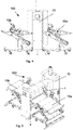
- 1 shows an isometric view of a device according to the invention
- 2 shows a side view according to FIG Figure 1
- Figure 3 shows a front view of the device according to the invention according to FIG 1
- 4 shows a side view of an arrangement with a device according to the invention
- figure 5 shows an isometric view of an arrangement according to the invention.
- the device 10 comprises a first roller 1 and a second roller 2, which are arranged one above the other in the distance to each other seen in the transport plane in which the dough strip is transported.
- the first roller 1 and the second roller 2 are spaced apart from one another, so that a strip of dough can be transported between the first roller 1 and the second roller 2 ( 3 ).
- the first roller 1 and the second roller 2 are each driven by a drive 30 via a belt drive 31 and are rotated by the drive 30 in their axis.
- the direction of rotation of the first roller 1 and the second roller 2 is in opposite directions and depending on the transport direction of the dough sheet, for example, the first roller 1 is driven clockwise and the second roller 2 counterclockwise or vice versa.
- the device 10 also includes a height adjustment device 7, with which, in this embodiment, the first roller 1 can be adjusted normal to the transport direction of the dough strip.
- the device 10 also has a lateral adjustment device 6 with which, in this embodiment, the first roller 1 can be adjusted in the transport direction of the dough strip.
- the arrangement of the first roller 1 with the height adjustment device 7 and the lateral adjustment device 6 makes it possible to change both the distance between the first roller 1 and the second roller 2 and a relative adjustment of the first roller 1 to the second roller 2 in the transport direction of the dough band.
- the lateral adjustment device 6 comprises two bearing plates 12a and 12b, which are each arranged laterally on one of the end faces of the first roller 1 ( 3 ).
- the bearings 17 of the first roller 1 are each arranged in the end shields 12a, 12b, whereby the first Roller 1 is rotatably mounted relative to the end shields 12a, 12b.
- the lateral adjustment device 6 also has two adjustment devices 60a, 60b, which are each connected to one of the bearing plates 12a and 12b.
- the end shields 12a, 12b are each adjusted in the transport direction of the dough strip by the adjusting devices 60a and 60b, as a result of which the first roller 1 can be adjusted relative to the second roller 2 in the transport direction of the dough strip.
- the adjustment devices 60a, 60b of the lateral adjustment device 6 each have a linear drive 11 which is designed as a hydraulic cylinder.
- the adjusting devices 60a, 60b also each have a U-shaped adjusting lever 62a, 62, with which the respective bearing plate 12a, 12b is connected to the linear drive 11 and can thereby be adjusted.
- the adjusting levers 62a, 62b can each be pivoted about a pivot axis 64, as a result of which a change in the stroke of the linear drive 11 leads to a rotation of the adjusting lever 62a, 62b and thus the respective bearing plate 12a, 12b in the transport direction of a possibly between the first roller 1 and the second Roller 2 inserted dough band is adjusted. Since an adjusting device 60a, 60b is arranged on each side of the first roller 1 and can be adjusted independently of one another, the first roller 1 can also be arranged at an angle with respect to the transport direction of the dough strip, whereby the axis of the first roller 1 is aligned with the axis of the second axis 2 can be adjusted at an angle.
- the lateral adjustment device 6 also has four sliding elements 9 for each bearing plate 12a, 12b, on which the respective bearing plates 12a, 12b can be linearly adjusted.
- the sliding elements 9 thus make it possible to easily adjust the end shields 12a, 12b in the direction of the transport direction of a sheet of dough.
- the height adjustment device 7 of the device 10 has two side plates 8a, 8b, which are each arranged on one of the end faces of the first roller 1.
- the side plates 8a, 8b are each fastened to the device 10 via four sliding elements 9, the sliding elements 9 enabling a movement along the height, ie normal to the transport direction of the dough strip.
- the sliding elements 9 are arranged on the side plates 8a, 8b in each of the four corner regions of the side plates 8a, 8b and are positioned in a small cutout.
- the height adjustment device 7 also has two linear drives 11, with which one of the side plates 8a, 8b can be adjusted in height, ie normal to the transport direction of the dough strip or normal to the transport plane of the dough strip.
- Side plates 8a, 8b are also adjusted differently by the linear drives 11, so that a different height adjustment of the side plates 8a, 8b can be applied. Due to the different adjustment of the side plates 8a, 8b, the axis of the roller 1 can be set at an angle to the axis of the roller 2 and in this way a different thickness can be set along the width of the dough strip.
- the side adjustment device 6 can optionally be attached to the height adjustment device 7, whereby the adjustment of the height adjustment device 7 or the first roller 1 to the second roller 2 also causes an adjustment of the side adjustment device 6 normal to the transport direction of the dough sheet.
- the sliding elements 9 of the lateral adjustment device 6 or the end plates 12a, 12b can be connected to the side plates 8a, 8b of the height adjustment device 7 and the lateral adjustment device 6 can thus adjust the end plates 12a, 12b relative to the side plates 8a, 8b and thus an adjustment cause the first roller 1 in the transport direction of the dough sheet.
- the linear drives 11 of the height adjustment device 7 and/or the lateral adjustment device 6 can be used as pneumatic cylinders, linear motors, spindle drives or, as in the Figures 1 to 3 shown, be designed as a hydraulic cylinder.
- other adjustment options for the adjustment device 6 or the height adjustment device 7 are also possible; for example, they could be adjusted via belt drives or other drives known from the prior art.
- the side plates 8a, 8b have a cutout through which the second roller 2 is mounted.
- the second roller 2 can also have a height adjustment device 7 and a lateral adjustment device 6 and can be adjusted in this way relative to the first roller 1 or to the dough sheet.
- a similar design of the height adjustment device 7 or the lateral adjustment device 6 for the second roller 2 could be provided in the device 10 .
- the side plates 8a, 8b of the height adjustment device 7 could be arranged pivoted about the center of the side adjustment device 6 and a height adjustment device 7 and side adjustment device 6 - similar to those provided for the first roller 1 - could also be arranged for the bearings of the second roller 2 on the device 10 be.
- the first roll 1 and the second roll 2 can be designed as a so-called satellite roll, such rolls having a so-called sun roll, which is arranged in the center of the roll, and a number of satellite rolls which are arranged evenly distributed around this sun roll .
- the first roller 1 and/or the second roller 2 also have other roller shapes or are designed, for example, as shaping rollers or transverse rollers.
- FIG. 4 and 5 is an arrangement 100 according to the invention in an isometric view ( figure 5 ) and a side view ( 4 ) shown.
- the device 10 according to the invention can be provided within a rolling system or a rolling mill for strips of dough that the device 10 according to the invention is arranged before and/or after other processing systems.
- the device 10 is arranged in the transfer area of a strip of dough from a first conveyor belt 15a to a second conveyor belt 15b.
- a strip of dough, not shown, would then be introduced into the device 10 by the first conveyor belt 15a and thus conveyed through between the first roller 1 and the second roller 2 and then transferred again to a second conveyor belt 15b.
- the distance between the first roller 1 and the second roller 2 or by changing the angle of the axis of the first roller 1 to the second roller 2 the flow rate and the flow behavior along the width of the dough sheet or within the dough sheet can be positively changed.
- the second roller 2 i.e. the roller lying below, is adjustable, i.e. has a height adjustment device 7 and a lateral adjustment device 6, and the first roller 1 is rigidly connected to the device 10.
Landscapes
- Life Sciences & Earth Sciences (AREA)
- Engineering & Computer Science (AREA)
- Food Science & Technology (AREA)
- Chemical & Material Sciences (AREA)
- Polymers & Plastics (AREA)
- Manufacturing And Processing Devices For Dough (AREA)
Applications Claiming Priority (2)
| Application Number | Priority Date | Filing Date | Title |
|---|---|---|---|
| ATA50972/2016A AT518997B1 (de) | 2016-10-21 | 2016-10-21 | Vorrichtung zum Bearbeiten und Transportieren von Teigbändern |
| PCT/AT2017/060281 WO2018071949A1 (de) | 2016-10-21 | 2017-10-20 | Vorrichtung zum bearbeiten und transportieren von teigbändern |
Publications (2)
| Publication Number | Publication Date |
|---|---|
| EP3528633A1 EP3528633A1 (de) | 2019-08-28 |
| EP3528633B1 true EP3528633B1 (de) | 2022-05-11 |
Family
ID=60191048
Family Applications (1)
| Application Number | Title | Priority Date | Filing Date |
|---|---|---|---|
| EP17791544.4A Not-in-force EP3528633B1 (de) | 2016-10-21 | 2017-10-20 | Vorrichtung zum bearbeiten und transportieren von teigbändern |
Country Status (4)
| Country | Link |
|---|---|
| EP (1) | EP3528633B1 (pl) |
| AT (1) | AT518997B1 (pl) |
| PL (1) | PL3528633T3 (pl) |
| WO (1) | WO2018071949A1 (pl) |
Families Citing this family (1)
| Publication number | Priority date | Publication date | Assignee | Title |
|---|---|---|---|---|
| CN116458666B (zh) * | 2023-04-18 | 2025-12-05 | 安徽金香丝薯业有限公司 | 一种无明矾红薯粉丝的加工装置 |
Family Cites Families (8)
| Publication number | Priority date | Publication date | Assignee | Title |
|---|---|---|---|---|
| JPH02231033A (ja) * | 1989-03-06 | 1990-09-13 | Rheon Autom Mach Co Ltd | 生地延展方法及び装置 |
| ES2262498T3 (es) * | 2000-11-03 | 2006-12-01 | Seewer Ag | Dispositivo y procedimiento para aplanar una banda de masa alimentacia. |
| JP3949992B2 (ja) * | 2002-04-02 | 2007-07-25 | レオン自動機株式会社 | 食品生地の延展方法及び装置 |
| NZ537272A (en) * | 2002-06-10 | 2005-10-28 | Rheon Automatic Machinery Co | An apparatus and method for beating and rolling a food dough belt |
| DE20212725U1 (de) * | 2002-08-14 | 2002-11-28 | A. Fritsch Gmbh & Co Kg, 97348 Markt Einersheim | Kombiniertes Quer- und Längswalzwerk |
| CA2467544C (en) * | 2002-09-03 | 2007-03-20 | Torahiko Hayashi | An apparatus and method for beating and rolling a food dough belt |
| AT508443A1 (de) * | 2009-07-07 | 2011-01-15 | Koenig Maschinen Gmbh | Walzvorrichtung |
| AT512952B1 (de) * | 2012-06-08 | 2015-04-15 | Haas Food Equipment Gmbh | Vorrichtung zur Bildung eines flach ausgewalzten, kontinuierlich geförderten Teigbandes |
-
2016
- 2016-10-21 AT ATA50972/2016A patent/AT518997B1/de active
-
2017
- 2017-10-20 PL PL17791544.4T patent/PL3528633T3/pl unknown
- 2017-10-20 WO PCT/AT2017/060281 patent/WO2018071949A1/de not_active Ceased
- 2017-10-20 EP EP17791544.4A patent/EP3528633B1/de not_active Not-in-force
Also Published As
| Publication number | Publication date |
|---|---|
| PL3528633T3 (pl) | 2022-07-18 |
| AT518997B1 (de) | 2018-03-15 |
| AT518997A4 (de) | 2018-03-15 |
| WO2018071949A1 (de) | 2018-04-26 |
| EP3528633A1 (de) | 2019-08-28 |
Similar Documents
| Publication | Publication Date | Title |
|---|---|---|
| EP0883566B1 (de) | Schwertfalzwerk | |
| DE1246291B (de) | Blatttransport- und Ausrichtvorrichtung | |
| EP2666560A1 (de) | Richtmaschine mit verstellbaren Stützrollenträger | |
| DE102012202477B4 (de) | Medienrotations- und Verschiebevorrichtung | |
| EP1949982B1 (de) | Walzvorrichtung und Verfahren zum Einrollen von Verbindungsstegen in Profile | |
| EP3866992B1 (de) | Vorrichtung und verfahren zum flexiblen rollformen eines halbzeugs | |
| EP2424687A1 (de) | Spritzbalken, strecke und verfahren zum aufbringen eines mediums auf ein produkt | |
| AT518997B1 (de) | Vorrichtung zum Bearbeiten und Transportieren von Teigbändern | |
| EP3661684B1 (de) | Wälzfräsmaschine, umfassend einen wälzfrässchlitten und einen anfasschlitten auf einem gemeinsamen schienensystem | |
| DE69209632T2 (de) | Verfahren und Vorrichtung zum Walzen von Metallen zur Herstellung von rundem Stabmaterial oder Walzdraht aus rundem Stab- oder Drahtmaterial mit grösserem Durchmesser | |
| EP2055660A1 (de) | Vorrichtung zum getakteten Umlenken von flächigen Gegenständen | |
| EP0102014B1 (de) | Walzgerüst zum Auswalzen von Bandmaterial unterschiedlicher Breite | |
| EP0103667B1 (de) | Doppelrollenführung für Walzwerke | |
| DE2729938C3 (de) | Doppelbandpresse zum Herstellen von Preßplatten | |
| EP4103329B1 (de) | Drehmomentstütze zum abfangen von antriebsmomenten und walzenanordnung mit einer drehmomentstütze | |
| WO2006133936A1 (de) | Vorrichtung zum bearbeiten von blattförmigen wertdokumenten | |
| EP0305559A1 (de) | Andruckvorrichtung für im Durchlauf arbeitende Kantenanleim-, Postforming- oder Ummantelungsmaschinen | |
| WO2025185822A1 (de) | Walzenanordnung zum vorschieben von blechmaterial | |
| DE1935438A1 (de) | Vorrichtung zum Zusammenfuehren und Vereinigen bewegter Werkstoffbahnen zwischen umlaufenden Walzen | |
| DE19912353B4 (de) | Vorrichtung zum Biegen eines strangförmigen Winkelprofils | |
| DE10010053A1 (de) | Stahlplatten-Richtmaschine | |
| DE102023102125A1 (de) | Teigverarbeitungsvorrichtung mit schwenkbaren Führungselementen | |
| DE3234307C2 (pl) | ||
| EP4477352A1 (de) | Bearbeitungswerkzeug | |
| DE102023102117A1 (de) | Gurtniederhalter und Gurtförderer |
Legal Events
| Date | Code | Title | Description |
|---|---|---|---|
| STAA | Information on the status of an ep patent application or granted ep patent |
Free format text: STATUS: UNKNOWN |
|
| STAA | Information on the status of an ep patent application or granted ep patent |
Free format text: STATUS: THE INTERNATIONAL PUBLICATION HAS BEEN MADE |
|
| PUAI | Public reference made under article 153(3) epc to a published international application that has entered the european phase |
Free format text: ORIGINAL CODE: 0009012 |
|
| STAA | Information on the status of an ep patent application or granted ep patent |
Free format text: STATUS: REQUEST FOR EXAMINATION WAS MADE |
|
| 17P | Request for examination filed |
Effective date: 20190513 |
|
| AK | Designated contracting states |
Kind code of ref document: A1 Designated state(s): AL AT BE BG CH CY CZ DE DK EE ES FI FR GB GR HR HU IE IS IT LI LT LU LV MC MK MT NL NO PL PT RO RS SE SI SK SM TR |
|
| AX | Request for extension of the european patent |
Extension state: BA ME |
|
| DAV | Request for validation of the european patent (deleted) | ||
| DAX | Request for extension of the european patent (deleted) | ||
| STAA | Information on the status of an ep patent application or granted ep patent |
Free format text: STATUS: EXAMINATION IS IN PROGRESS |
|
| 17Q | First examination report despatched |
Effective date: 20200914 |
|
| GRAP | Despatch of communication of intention to grant a patent |
Free format text: ORIGINAL CODE: EPIDOSNIGR1 |
|
| STAA | Information on the status of an ep patent application or granted ep patent |
Free format text: STATUS: GRANT OF PATENT IS INTENDED |
|
| INTG | Intention to grant announced |
Effective date: 20220110 |
|
| GRAS | Grant fee paid |
Free format text: ORIGINAL CODE: EPIDOSNIGR3 |
|
| GRAA | (expected) grant |
Free format text: ORIGINAL CODE: 0009210 |
|
| STAA | Information on the status of an ep patent application or granted ep patent |
Free format text: STATUS: THE PATENT HAS BEEN GRANTED |
|
| AK | Designated contracting states |
Kind code of ref document: B1 Designated state(s): AL AT BE BG CH CY CZ DE DK EE ES FI FR GB GR HR HU IE IS IT LI LT LU LV MC MK MT NL NO PL PT RO RS SE SI SK SM TR |
|
| REG | Reference to a national code |
Ref country code: GB Ref legal event code: FG4D Free format text: NOT ENGLISH |
|
| REG | Reference to a national code |
Ref country code: CH Ref legal event code: EP |
|
| REG | Reference to a national code |
Ref country code: AT Ref legal event code: REF Ref document number: 1490618 Country of ref document: AT Kind code of ref document: T Effective date: 20220515 |
|
| REG | Reference to a national code |
Ref country code: DE Ref legal event code: R096 Ref document number: 502017013179 Country of ref document: DE |
|
| REG | Reference to a national code |
Ref country code: IE Ref legal event code: FG4D Free format text: LANGUAGE OF EP DOCUMENT: GERMAN |
|
| REG | Reference to a national code |
Ref country code: NO Ref legal event code: T2 Effective date: 20220511 |
|
| REG | Reference to a national code |
Ref country code: LT Ref legal event code: MG9D |
|
| REG | Reference to a national code |
Ref country code: NL Ref legal event code: MP Effective date: 20220511 |
|
| PG25 | Lapsed in a contracting state [announced via postgrant information from national office to epo] |
Ref country code: SE Free format text: LAPSE BECAUSE OF FAILURE TO SUBMIT A TRANSLATION OF THE DESCRIPTION OR TO PAY THE FEE WITHIN THE PRESCRIBED TIME-LIMIT Effective date: 20220511 Ref country code: PT Free format text: LAPSE BECAUSE OF FAILURE TO SUBMIT A TRANSLATION OF THE DESCRIPTION OR TO PAY THE FEE WITHIN THE PRESCRIBED TIME-LIMIT Effective date: 20220912 Ref country code: NL Free format text: LAPSE BECAUSE OF FAILURE TO SUBMIT A TRANSLATION OF THE DESCRIPTION OR TO PAY THE FEE WITHIN THE PRESCRIBED TIME-LIMIT Effective date: 20220511 Ref country code: LT Free format text: LAPSE BECAUSE OF FAILURE TO SUBMIT A TRANSLATION OF THE DESCRIPTION OR TO PAY THE FEE WITHIN THE PRESCRIBED TIME-LIMIT Effective date: 20220511 Ref country code: HR Free format text: LAPSE BECAUSE OF FAILURE TO SUBMIT A TRANSLATION OF THE DESCRIPTION OR TO PAY THE FEE WITHIN THE PRESCRIBED TIME-LIMIT Effective date: 20220511 Ref country code: GR Free format text: LAPSE BECAUSE OF FAILURE TO SUBMIT A TRANSLATION OF THE DESCRIPTION OR TO PAY THE FEE WITHIN THE PRESCRIBED TIME-LIMIT Effective date: 20220812 Ref country code: FI Free format text: LAPSE BECAUSE OF FAILURE TO SUBMIT A TRANSLATION OF THE DESCRIPTION OR TO PAY THE FEE WITHIN THE PRESCRIBED TIME-LIMIT Effective date: 20220511 Ref country code: ES Free format text: LAPSE BECAUSE OF FAILURE TO SUBMIT A TRANSLATION OF THE DESCRIPTION OR TO PAY THE FEE WITHIN THE PRESCRIBED TIME-LIMIT Effective date: 20220511 Ref country code: BG Free format text: LAPSE BECAUSE OF FAILURE TO SUBMIT A TRANSLATION OF THE DESCRIPTION OR TO PAY THE FEE WITHIN THE PRESCRIBED TIME-LIMIT Effective date: 20220811 |
|
| PG25 | Lapsed in a contracting state [announced via postgrant information from national office to epo] |
Ref country code: RS Free format text: LAPSE BECAUSE OF FAILURE TO SUBMIT A TRANSLATION OF THE DESCRIPTION OR TO PAY THE FEE WITHIN THE PRESCRIBED TIME-LIMIT Effective date: 20220511 Ref country code: LV Free format text: LAPSE BECAUSE OF FAILURE TO SUBMIT A TRANSLATION OF THE DESCRIPTION OR TO PAY THE FEE WITHIN THE PRESCRIBED TIME-LIMIT Effective date: 20220511 Ref country code: IS Free format text: LAPSE BECAUSE OF FAILURE TO SUBMIT A TRANSLATION OF THE DESCRIPTION OR TO PAY THE FEE WITHIN THE PRESCRIBED TIME-LIMIT Effective date: 20220911 |
|
| PG25 | Lapsed in a contracting state [announced via postgrant information from national office to epo] |
Ref country code: SM Free format text: LAPSE BECAUSE OF FAILURE TO SUBMIT A TRANSLATION OF THE DESCRIPTION OR TO PAY THE FEE WITHIN THE PRESCRIBED TIME-LIMIT Effective date: 20220511 Ref country code: SK Free format text: LAPSE BECAUSE OF FAILURE TO SUBMIT A TRANSLATION OF THE DESCRIPTION OR TO PAY THE FEE WITHIN THE PRESCRIBED TIME-LIMIT Effective date: 20220511 Ref country code: RO Free format text: LAPSE BECAUSE OF FAILURE TO SUBMIT A TRANSLATION OF THE DESCRIPTION OR TO PAY THE FEE WITHIN THE PRESCRIBED TIME-LIMIT Effective date: 20220511 Ref country code: EE Free format text: LAPSE BECAUSE OF FAILURE TO SUBMIT A TRANSLATION OF THE DESCRIPTION OR TO PAY THE FEE WITHIN THE PRESCRIBED TIME-LIMIT Effective date: 20220511 Ref country code: DK Free format text: LAPSE BECAUSE OF FAILURE TO SUBMIT A TRANSLATION OF THE DESCRIPTION OR TO PAY THE FEE WITHIN THE PRESCRIBED TIME-LIMIT Effective date: 20220511 Ref country code: CZ Free format text: LAPSE BECAUSE OF FAILURE TO SUBMIT A TRANSLATION OF THE DESCRIPTION OR TO PAY THE FEE WITHIN THE PRESCRIBED TIME-LIMIT Effective date: 20220511 |
|
| REG | Reference to a national code |
Ref country code: DE Ref legal event code: R097 Ref document number: 502017013179 Country of ref document: DE |
|
| PLBE | No opposition filed within time limit |
Free format text: ORIGINAL CODE: 0009261 |
|
| STAA | Information on the status of an ep patent application or granted ep patent |
Free format text: STATUS: NO OPPOSITION FILED WITHIN TIME LIMIT |
|
| PG25 | Lapsed in a contracting state [announced via postgrant information from national office to epo] |
Ref country code: AL Free format text: LAPSE BECAUSE OF FAILURE TO SUBMIT A TRANSLATION OF THE DESCRIPTION OR TO PAY THE FEE WITHIN THE PRESCRIBED TIME-LIMIT Effective date: 20220511 |
|
| 26N | No opposition filed |
Effective date: 20230214 |
|
| PG25 | Lapsed in a contracting state [announced via postgrant information from national office to epo] |
Ref country code: SI Free format text: LAPSE BECAUSE OF FAILURE TO SUBMIT A TRANSLATION OF THE DESCRIPTION OR TO PAY THE FEE WITHIN THE PRESCRIBED TIME-LIMIT Effective date: 20220511 Ref country code: MC Free format text: LAPSE BECAUSE OF FAILURE TO SUBMIT A TRANSLATION OF THE DESCRIPTION OR TO PAY THE FEE WITHIN THE PRESCRIBED TIME-LIMIT Effective date: 20220511 |
|
| REG | Reference to a national code |
Ref country code: CH Ref legal event code: PL |
|
| REG | Reference to a national code |
Ref country code: BE Ref legal event code: MM Effective date: 20221031 |
|
| GBPC | Gb: european patent ceased through non-payment of renewal fee |
Effective date: 20221020 |
|
| PG25 | Lapsed in a contracting state [announced via postgrant information from national office to epo] |
Ref country code: LU Free format text: LAPSE BECAUSE OF NON-PAYMENT OF DUE FEES Effective date: 20221020 |
|
| PG25 | Lapsed in a contracting state [announced via postgrant information from national office to epo] |
Ref country code: LI Free format text: LAPSE BECAUSE OF NON-PAYMENT OF DUE FEES Effective date: 20221031 Ref country code: CH Free format text: LAPSE BECAUSE OF NON-PAYMENT OF DUE FEES Effective date: 20221031 |
|
| PG25 | Lapsed in a contracting state [announced via postgrant information from national office to epo] |
Ref country code: BE Free format text: LAPSE BECAUSE OF NON-PAYMENT OF DUE FEES Effective date: 20221031 |
|
| PG25 | Lapsed in a contracting state [announced via postgrant information from national office to epo] |
Ref country code: IE Free format text: LAPSE BECAUSE OF NON-PAYMENT OF DUE FEES Effective date: 20221020 Ref country code: GB Free format text: LAPSE BECAUSE OF NON-PAYMENT OF DUE FEES Effective date: 20221020 |
|
| REG | Reference to a national code |
Ref country code: AT Ref legal event code: MM01 Ref document number: 1490618 Country of ref document: AT Kind code of ref document: T Effective date: 20221020 |
|
| PG25 | Lapsed in a contracting state [announced via postgrant information from national office to epo] |
Ref country code: IT Free format text: LAPSE BECAUSE OF FAILURE TO SUBMIT A TRANSLATION OF THE DESCRIPTION OR TO PAY THE FEE WITHIN THE PRESCRIBED TIME-LIMIT Effective date: 20220511 Ref country code: AT Free format text: LAPSE BECAUSE OF NON-PAYMENT OF DUE FEES Effective date: 20221020 |
|
| PGFP | Annual fee paid to national office [announced via postgrant information from national office to epo] |
Ref country code: NO Payment date: 20231025 Year of fee payment: 7 Ref country code: FR Payment date: 20231026 Year of fee payment: 7 Ref country code: DE Payment date: 20231020 Year of fee payment: 7 |
|
| PGFP | Annual fee paid to national office [announced via postgrant information from national office to epo] |
Ref country code: PL Payment date: 20231013 Year of fee payment: 7 |
|
| PG25 | Lapsed in a contracting state [announced via postgrant information from national office to epo] |
Ref country code: HU Free format text: LAPSE BECAUSE OF FAILURE TO SUBMIT A TRANSLATION OF THE DESCRIPTION OR TO PAY THE FEE WITHIN THE PRESCRIBED TIME-LIMIT; INVALID AB INITIO Effective date: 20171020 |
|
| PG25 | Lapsed in a contracting state [announced via postgrant information from national office to epo] |
Ref country code: CY Free format text: LAPSE BECAUSE OF FAILURE TO SUBMIT A TRANSLATION OF THE DESCRIPTION OR TO PAY THE FEE WITHIN THE PRESCRIBED TIME-LIMIT Effective date: 20220511 |
|
| PG25 | Lapsed in a contracting state [announced via postgrant information from national office to epo] |
Ref country code: MK Free format text: LAPSE BECAUSE OF FAILURE TO SUBMIT A TRANSLATION OF THE DESCRIPTION OR TO PAY THE FEE WITHIN THE PRESCRIBED TIME-LIMIT Effective date: 20220511 |
|
| PG25 | Lapsed in a contracting state [announced via postgrant information from national office to epo] |
Ref country code: TR Free format text: LAPSE BECAUSE OF FAILURE TO SUBMIT A TRANSLATION OF THE DESCRIPTION OR TO PAY THE FEE WITHIN THE PRESCRIBED TIME-LIMIT Effective date: 20220511 |
|
| PG25 | Lapsed in a contracting state [announced via postgrant information from national office to epo] |
Ref country code: MT Free format text: LAPSE BECAUSE OF FAILURE TO SUBMIT A TRANSLATION OF THE DESCRIPTION OR TO PAY THE FEE WITHIN THE PRESCRIBED TIME-LIMIT Effective date: 20220511 |
|
| PG25 | Lapsed in a contracting state [announced via postgrant information from national office to epo] |
Ref country code: BG Free format text: LAPSE BECAUSE OF FAILURE TO SUBMIT A TRANSLATION OF THE DESCRIPTION OR TO PAY THE FEE WITHIN THE PRESCRIBED TIME-LIMIT Effective date: 20220511 |
|
| PG25 | Lapsed in a contracting state [announced via postgrant information from national office to epo] |
Ref country code: BG Free format text: LAPSE BECAUSE OF FAILURE TO SUBMIT A TRANSLATION OF THE DESCRIPTION OR TO PAY THE FEE WITHIN THE PRESCRIBED TIME-LIMIT Effective date: 20220511 |
|
| REG | Reference to a national code |
Ref country code: DE Ref legal event code: R119 Ref document number: 502017013179 Country of ref document: DE |
|
| PG25 | Lapsed in a contracting state [announced via postgrant information from national office to epo] |
Ref country code: DE Free format text: LAPSE BECAUSE OF NON-PAYMENT OF DUE FEES Effective date: 20250501 |
|
| PG25 | Lapsed in a contracting state [announced via postgrant information from national office to epo] |
Ref country code: NO Free format text: LAPSE BECAUSE OF NON-PAYMENT OF DUE FEES Effective date: 20241031 |
|
| PG25 | Lapsed in a contracting state [announced via postgrant information from national office to epo] |
Ref country code: FR Free format text: LAPSE BECAUSE OF NON-PAYMENT OF DUE FEES Effective date: 20241031 |
|
| PG25 | Lapsed in a contracting state [announced via postgrant information from national office to epo] |
Ref country code: PL Free format text: LAPSE BECAUSE OF NON-PAYMENT OF DUE FEES Effective date: 20241020 |