EP3528511B1 - Ultraschallsonde und verfahren zur herstellung der ultraschallsonde - Google Patents
Ultraschallsonde und verfahren zur herstellung der ultraschallsonde Download PDFInfo
- Publication number
- EP3528511B1 EP3528511B1 EP17860917.8A EP17860917A EP3528511B1 EP 3528511 B1 EP3528511 B1 EP 3528511B1 EP 17860917 A EP17860917 A EP 17860917A EP 3528511 B1 EP3528511 B1 EP 3528511B1
- Authority
- EP
- European Patent Office
- Prior art keywords
- conductive
- parts
- conductive part
- ultrasound probe
- piezoelectric elements
- Prior art date
- Legal status (The legal status is an assumption and is not a legal conclusion. Google has not performed a legal analysis and makes no representation as to the accuracy of the status listed.)
- Active
Links
Images


Classifications
-
- A—HUMAN NECESSITIES
- A61—MEDICAL OR VETERINARY SCIENCE; HYGIENE
- A61B—DIAGNOSIS; SURGERY; IDENTIFICATION
- A61B8/00—Diagnosis using ultrasonic, sonic or infrasonic waves
- A61B8/44—Constructional features of the ultrasonic, sonic or infrasonic diagnostic device
- A61B8/4444—Constructional features of the ultrasonic, sonic or infrasonic diagnostic device related to the probe
-
- A—HUMAN NECESSITIES
- A61—MEDICAL OR VETERINARY SCIENCE; HYGIENE
- A61B—DIAGNOSIS; SURGERY; IDENTIFICATION
- A61B8/00—Diagnosis using ultrasonic, sonic or infrasonic waves
- A61B8/13—Tomography
- A61B8/14—Echo-tomography
-
- B—PERFORMING OPERATIONS; TRANSPORTING
- B06—GENERATING OR TRANSMITTING MECHANICAL VIBRATIONS IN GENERAL
- B06B—METHODS OR APPARATUS FOR GENERATING OR TRANSMITTING MECHANICAL VIBRATIONS OF INFRASONIC, SONIC, OR ULTRASONIC FREQUENCY, e.g. FOR PERFORMING MECHANICAL WORK IN GENERAL
- B06B1/00—Methods or apparatus for generating mechanical vibrations of infrasonic, sonic, or ultrasonic frequency
- B06B1/02—Methods or apparatus for generating mechanical vibrations of infrasonic, sonic, or ultrasonic frequency making use of electrical energy
- B06B1/06—Methods or apparatus for generating mechanical vibrations of infrasonic, sonic, or ultrasonic frequency making use of electrical energy operating with piezoelectric effect or with electrostriction
- B06B1/0607—Methods or apparatus for generating mechanical vibrations of infrasonic, sonic, or ultrasonic frequency making use of electrical energy operating with piezoelectric effect or with electrostriction using multiple elements
- B06B1/0622—Methods or apparatus for generating mechanical vibrations of infrasonic, sonic, or ultrasonic frequency making use of electrical energy operating with piezoelectric effect or with electrostriction using multiple elements on one surface
- B06B1/0629—Square array
-
- B—PERFORMING OPERATIONS; TRANSPORTING
- B06—GENERATING OR TRANSMITTING MECHANICAL VIBRATIONS IN GENERAL
- B06B—METHODS OR APPARATUS FOR GENERATING OR TRANSMITTING MECHANICAL VIBRATIONS OF INFRASONIC, SONIC, OR ULTRASONIC FREQUENCY, e.g. FOR PERFORMING MECHANICAL WORK IN GENERAL
- B06B1/00—Methods or apparatus for generating mechanical vibrations of infrasonic, sonic, or ultrasonic frequency
- B06B1/02—Methods or apparatus for generating mechanical vibrations of infrasonic, sonic, or ultrasonic frequency making use of electrical energy
- B06B1/06—Methods or apparatus for generating mechanical vibrations of infrasonic, sonic, or ultrasonic frequency making use of electrical energy operating with piezoelectric effect or with electrostriction
- B06B1/0688—Methods or apparatus for generating mechanical vibrations of infrasonic, sonic, or ultrasonic frequency making use of electrical energy operating with piezoelectric effect or with electrostriction with foil-type piezoelectric elements, e.g. PVDF
- B06B1/0692—Methods or apparatus for generating mechanical vibrations of infrasonic, sonic, or ultrasonic frequency making use of electrical energy operating with piezoelectric effect or with electrostriction with foil-type piezoelectric elements, e.g. PVDF with a continuous electrode on one side and a plurality of electrodes on the other side
-
- H—ELECTRICITY
- H04—ELECTRIC COMMUNICATION TECHNIQUE
- H04R—LOUDSPEAKERS, MICROPHONES, GRAMOPHONE PICK-UPS OR LIKE ACOUSTIC ELECTROMECHANICAL TRANSDUCERS; ELECTRIC HEARING AIDS; PUBLIC ADDRESS SYSTEMS
- H04R17/00—Piezoelectric transducers; Electrostrictive transducers
-
- H—ELECTRICITY
- H04—ELECTRIC COMMUNICATION TECHNIQUE
- H04R—LOUDSPEAKERS, MICROPHONES, GRAMOPHONE PICK-UPS OR LIKE ACOUSTIC ELECTROMECHANICAL TRANSDUCERS; ELECTRIC HEARING AIDS; PUBLIC ADDRESS SYSTEMS
- H04R17/00—Piezoelectric transducers; Electrostrictive transducers
- H04R17/10—Resonant transducers, i.e. adapted to produce maximum output at a predetermined frequency
-
- H—ELECTRICITY
- H04—ELECTRIC COMMUNICATION TECHNIQUE
- H04R—LOUDSPEAKERS, MICROPHONES, GRAMOPHONE PICK-UPS OR LIKE ACOUSTIC ELECTROMECHANICAL TRANSDUCERS; ELECTRIC HEARING AIDS; PUBLIC ADDRESS SYSTEMS
- H04R31/00—Apparatus or processes specially adapted for the manufacture of transducers or diaphragms therefor
Definitions
- the invention relates to an ultrasound probe and a method of manufacturing an ultrasound probe, and relates to an ultrasound probe including high-sensitive piezoelectric elements.
- an ultrasound diagnostic apparatus using an ultrasound image has been put to practical use in the medical field.
- this kind of ultrasound diagnostic apparatus generates an ultrasound image by transmitting an ultrasound beam toward a test subject from an ultrasound probe, receiving an ultrasound echo from the test subject by the ultrasound probe, and electrically processing received signals.
- an arrangement pitch between the piezoelectric elements of the ultrasound probe is decreased according to a wavelength of an ultrasound.
- an ultrasound having a high frequency is transmitted and received in order to obtain a high-definition ultrasound image, and the wavelength of the ultrasound tends to be shortened. Accordingly, there is a need for a smaller arrangement pitch between the piezoelectric elements, that is, a narrower width of the piezoelectric elements.
- JP1997-215095A JP-H09-215095A discloses an ultrasound probe including a plurality of piezoelectric elements arranged so as to have a narrow width in order to generate an ultrasound having a high frequency by driving the piezoelectric elements with a high driving frequency.
- the plurality of piezoelectric elements is formed on a backing material in an array, and acoustic matching parts are respectively arranged on the piezoelectric elements.
- Each of the plurality of piezoelectric elements includes a driving electrode part on a lower surface and a ground electrode part on an upper surface, and a common connection lead is connected to the ground electrode part.
- US 2014/070668 Al discloses an ultrasonic probe having plural piezoelectric elements on a backing material along an arrangement direction.
- Each piezoelectric element includes a laminate in which a first conductive part, a piezoelectric body part and a second conductive part are laminated on a surface of the backing material.
- On the second conductive parts plural acoustic matching parts are provided.
- a fourth conductive part electrically connects the third conductive part to each other.
- the second and the third conductive parts and the fourth conductive part form a common electrode common to the plural piezoelectric elements.
- a driving electrode layer for forming the driving electrode part, a piezoelectric body layer made of a piezoelectric material, and a ground electrode layer for forming the ground electrode part which are formed as sheets are laminated on a surface of the backing material in order.
- a sheet-shaped acoustic matching layer for forming the acoustic matching parts is laminated on an upper surface of the ground electrode layer.
- a part of the upper surface of the ground electrode layer is exposed without being covered by the acoustic matching layer in order to be connected to the common connection lead. Subsequently, dicing for separating these layers at a predetermined pitch is performed.
- a portion of the upper surface of the ground electrode layer which is covered by the acoustic matching layer is protected from being damaged due to the dicing.
- the portion exposed without being covered by the acoustic matching layer is not protected from being damaged due to the dicing.
- the exposed portion of the ground electrode layer is broken, and thus, there is a concern that the sensitivity of the piezoelectric elements formed through the dicing will be degraded.
- the invention has been made in order to solve the problem of the related art, and an object of the invention is to provide an ultrasound probe including high-sensitive piezoelectric elements and a method of manufacturing an ultrasound probe.
- An ultrasound probe according to the invention is an ultrasound probe comprising the features of claim 1.
- the plurality of third conductive parts and the fourth conductive part can form a commonization conductive part which spreads over the plurality of piezoelectric elements and has a single-layer structure in a lamination direction of the laminates.
- the fourth conductive part can be constituted by a plurality of conductive fillers filling between the plurality of third conductive parts in the arrangement direction.
- the fourth conductive part may extend in the arrangement direction over the plurality of piezoelectric elements, and may be joined to side surfaces of the plurality of third conductive parts in the elevation direction.
- the plurality of third conductive parts and the fourth conductive part can form a commonization conductive part which spreads over the plurality of piezoelectric elements and has a structure in which a plurality of layers is laminated in the lamination direction of the laminates.
- the fourth conductive part extends in the arrangement direction over the plurality of piezoelectric elements and is joined to surfaces of the plurality of third conductive parts in the lamination direction of the laminates.
- Each of the plurality of third conductive parts may include a cut-out part cut such that a wall part protruding in the lamination direction of the laminates is formed at an end portion in the elevation direction, and the fourth conductive part may be arranged on the cut-out parts of the plurality of third conductive parts.
- each of the plurality of third conductive parts may include a groove extending in the arrangement direction, and the fourth conductive part may be arranged within the grooves of the plurality of third conductive parts.
- the fourth conductive part can have a lamination structure in which a plurality of layers is laminated in the lamination direction of the laminates.
- the third conductive part has an acoustic impedance higher than an acoustic impedance of the fourth conductive part.
- a thickness of the third conductive part has a value of substantially 1/4 of a wavelength in a case where an ultrasound having a resonance frequency of the piezoelectric body part propagates through the third conductive part
- a thickness of the fourth conductive part has a value of substantially 1/4 of a wavelength in a case where the ultrasound having the resonance frequency of the piezoelectric body part propagates through the fourth conductive part.
- a thickness of the commonization conductive part has a value of substantially 1/4 of an average wavelength in a case where an ultrasound having a resonance frequency of the piezoelectric body part propagates through the commonization conductive part.
- the third conductive part can have a lamination structure in which a plurality of layers is laminated in the lamination direction of the laminates.
- An insulation part can be further arranged on the commonization conductive part so as to correspond to the plurality of piezoelectric elements, and the insulation part can have an acoustic impedance lower than an acoustic impedance of the commonization conductive part.
- each of a thickness of the commonization conductive part and a thickness of the insulation part has a value of substantially 1/4 of an average wavelength in a case where an ultrasound having a resonance frequency of the piezoelectric body part propagates through the commonization conductive part.
- Commonization conductive parts may be respectively arranged at both end portions of the second conductive part of each of the plurality of piezoelectric elements in the elevation direction.
- the commonization conductive parts respectively arranged on both the end portions of the second conductive part of each of the plurality of piezoelectric elements in the elevation direction have sizes equal to each other and acoustic impedances equal to each other.
- a thickness of the commonization conductive part and a thickness of a portion of the acoustic matching part other than the third conductive part have values which are substantially equal to each other.
- a method of manufacturing an ultrasound probe according to the invention is a method including the steps of claim 19.
- the fourth conductive part can be formed by filling spaces between the third conductive layers of the plurality of composite laminates in the arrangement direction with conductive fillers.
- the fourth conductive part may extend in the arrangement direction over the plurality of piezoelectric elements, and may be joined to the third conductive layers of the plurality of composite laminates.
- the method of manufacturing an ultrasound probe may further comprise a step of filling spaces between the plurality of composite laminates with insulating fillers.
- the fourth conductive part that electrically connects the plurality of third conductive parts to each other is provided, and the plurality of third conductive parts and the fourth conductive part form the common electrode common to the plurality of piezoelectric elements, it is possible to realize the ultrasound probe including the high-sensitive piezoelectric elements.
- FIG. 1 A configuration of an ultrasound probe according to Embodiment 1 of the present invention is shown in Figs. 1 and 2 .
- a plurality of piezoelectric elements 2 is arranged on a backing material 1 in an array at a predetermined pitch P1 along an arrangement direction X, that is, an azimuth direction.
- the plurality of piezoelectric elements 2 extends in an elevation direction Y crossing the arrangement direction X.
- Each piezoelectric element 2 has a piezoelectric body part 21.
- a first conductive part 22 is joined to a surface of the piezoelectric body part 21 facing the backing material 1, and a second conductive part 23 is joined to the other surface of the piezoelectric body part 21. That is, each piezoelectric element 2 is constituted by a laminate in which the first conductive part 22, the piezoelectric body part 21, and the second conductive part 23 are laminated on a surface of the backing material 1 in order.
- the first conductive part 22 functions as a signal electrode of the piezoelectric element 2.
- the second conductive part 23 functions as a ground electrode of the piezoelectric element 2.
- Acoustic matching parts 3 are joined to the second conductive parts 23 of the plurality of piezoelectric elements 2, respectively.
- a main part 31 of the acoustic matching part 3 constitutes the most part of the acoustic matching part 3.
- a portion of the acoustic matching part 3 other than the main part 31 includes a third conductive part 32 joined to the second conductive part 23.
- the third conductive part 32 is arranged at an end portion of the acoustic matching part 3 in the elevation direction Y.
- a gap is formed between the piezoelectric elements 2 adjacent to each other, and these piezoelectric elements 2 are separated from each other through this gap.
- a gap is also formed between the acoustic matching parts 3 adjacent to each other, and these acoustic matching parts 3 are separated from each other through this gap.
- insulating fillers 4A fill the gaps between the piezoelectric elements 2 adjacent to each other, and thus, the positions of the plurality of piezoelectric elements 2 are fixed.
- Insulating fillers 4B also fill the gaps between the main parts 31 of the acoustic matching parts 3 adjacent to each other, and conductive fillers 5 fill gaps between the third conductive parts 32 of the acoustic matching parts 3 adjacent to each other.
- the plurality of insulating fillers 4B and the plurality of conductive fillers 5 are provided, and thus, the positions of the plurality of acoustic matching parts 3 are fixed.
- each conductive filler 5 joins the third conductive parts 32 adjacent in the arrangement direction X to each other, and the plurality of conductive fillers 5 forms a fourth conductive part 6 which electrically connects the plurality of third conductive parts 32 to each other.
- a commonization conductive part 7 which spreads over the plurality of piezoelectric elements 2 and has a single-layer structure in a lamination direction of the laminate constituting the piezoelectric element 2 is formed by the plurality of third conductive parts 32 and the fourth conductive part 6, and a common electrode common to the plurality of piezoelectric elements 2 is formed by the second conductive parts 23 of the plurality of piezoelectric elements 2 and the commonization conductive part 7.
- This common electrode causes the ground electrodes of the plurality of piezoelectric elements 2, that is, the second conductive parts 23 to be electrically grounded in common.
- the piezoelectric body part 21 of the piezoelectric element 2 is made of a known piezoelectric material.
- the piezoelectric material include piezo ceramics such as lead zirconate titanate (PZT) or polymer materials such as polyvinylidene fluoride (PVDF).
- the backing material 1 supports the plurality of piezoelectric elements 2 and absorbs ultrasounds emitted backwards, and is made of a rubber material such as ferrite rubber.
- Acoustic matching part 3 matches acoustic impedances of the piezoelectric body part 21 of the piezoelectric element 2 and a test subject used, and causes ultrasounds to be easily incident within the test subject.
- the main part 31 of the acoustic matching part 3 can be made of a material having an acoustic impedance which is lower than the acoustic impedance of the piezoelectric body part 21 and is higher than the acoustic impedance of the test subject.
- the main part 31 can be formed by laminating a plurality of layers made of such a material.
- a layer made of a material having an acoustic impedance lower than an acoustic impedance of a layer arranged on the second conductive part 23 of the piezoelectric element 2 is laminated on the layer arranged on the second conductive part, and thus, a layer structure in which the acoustic impedances gradually decrease from the piezoelectric body part 21 to the test subject is formed.
- the third conductive part 32 of the acoustic matching part 3 is made of a conductive material having an acoustic impedance which is lower than the acoustic impedance of the piezoelectric body part 21 and is higher than the acoustic impedance of the test subject.
- the insulating fillers 4A and 4B are made of an insulating resin material or the like.
- the resin material include a silicone resin and an epoxy resin.
- the plurality of conductive fillers 5 constituting the fourth conductive part 6 is made of a conductive material which has adhesiveness and conductivity to the third conductive part 32.
- the same material of the conductive material of the third conductive part 32 can be used as the conductive filler 5.
- the piezoelectric body parts 21 expand and contract by respectively applying pulsed or continuous wave voltages between the first conductive parts 22 of the plurality of piezoelectric elements 2 and the commonization conductive part 7 connected to the second conductive parts 23 of the plurality of piezoelectric elements 2, and thus, pulsed or continuous wave ultrasounds are generated.
- these ultrasounds are incident within the test subject through the acoustic matching parts 3, these ultrasounds are combined with each other, and thus, an ultrasound beam is formed.
- the ultrasound beam propagates within the test subject.
- the piezoelectric body parts 21 are deformed, and signal voltages are generated between the first conductive parts 22 and the second conductive parts 23 according to the deformation.
- the signal voltages generated in the plurality of piezoelectric elements 2 are extracted between the first conductive parts 22 of the piezoelectric elements 2 and the commonization conductive part 7, and are received as reception signals.
- An ultrasound image is generated based on the reception signals.
- the common electrode since the common electrode has the structure in which the third conductive parts 32 of the acoustic matching parts 3 are joined to the second conductive parts 23 of the piezoelectric elements 2, a cross-sectional area of the common electrode is larger than a cross-sectional area of the second conductive parts 23. Accordingly, the common electrode has an electrical impedance lower than an electrical impedance of an electrode acquired by integrally connecting the plurality of second conductive parts 23 to each other along the arrangement direction X.
- Such an ultrasound probe can be manufactured as follows.
- a sheet-like first conductive layer 122 is joined to the surface of the backing material 1 by using an adhesive as shown in Figs. 5 and 6 .
- the first conductive layer 122 and a sheet-like piezoelectric body layer 121 are joined to each other by an adhesive, and the piezoelectric body layer 121 and a sheet-like second conductive layer 123 are joined by an adhesive.
- the first conductive layer 122, the piezoelectric body layer 121, and the second conductive layer 123 are laminated on the surface of the backing material 1 in order.
- a sheet-like acoustic matching layer 131 extending in the arrangement direction X is joined by an adhesive so as to cover most of a surface of the second conductive layer 123.
- a conductive paste acquired by dispersing conductive particles in an insulating material such as a resin is applied on the surface, of the entire surface of the second conductive layer 123, which is not covered by the acoustic matching layer 131, in a sheet extending in the arrangement direction X.
- a third conductive layer 132 is formed by hardening the conductive paste through heating.
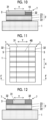
- the layers of the first conductive layer 122, the piezoelectric body layer 121, the second conductive layer 123, the acoustic matching layer 131, and the third conductive layer 132 are diced at the pitch P1 along the elevation direction Y crossing the arrangement direction X so as to reach the backing material 1 in the lamination direction. It is preferable that the pitch P1 becomes finer according to a driving frequency of the piezoelectric element 2 so as not to generate grating robes on the ultrasound image.
- the pitch P1 is equal to or less than 150 ⁇ m, and it is more preferable that the layers are sub-diced at a pitch of 50 to 60 ⁇ m or less in order to optimize vibration efficiency of the piezoelectric element 2. Since the second conductive layer 123 is covered by the acoustic matching layer 131 and the third conductive layer 132 at the time of dicing, the second conductive layer 123 is protected from being damaged due to the dicing. Accordingly, even in a case where the layers are diced at a small pitch P1, the second conductive layer 123 is effectively prevented from being broken.
- the layers of the first conductive layer 122, the piezoelectric body layer 121, the second conductive layer 123, the acoustic matching layer 131, and the third conductive layer 132 are separated from each other in the arrangement direction X through separation grooves 8 formed through the dicing. Accordingly, a plurality of composite laminates 9 arranged in an array at the pitch P1 along the arrangement direction X is formed.
- the plurality of composite laminates 9 is configured such that the first conductive parts 22, the piezoelectric body parts 21, and the second conductive parts 23 are laminated in order and the main parts 31 and the third conductive parts 32 of the acoustic matching parts 3 are arranged on the second conductive parts 23 so as to be line up in the elevation direction Y.
- the insulating fillers 4A fill gaps between the composite laminates 9 adjacent to each other, that is, the separation grooves 8, as shown in Fig. 8 .
- the insulating filler 4A fills the space from a lower end of the composite laminate 9 in the lamination direction, that is, the surface of the backing material 1 to an upper end of the piezoelectric element 2 constituted by the first conductive part 22, the piezoelectric body part 21, and the second conductive part 23.
- the insulating filler 4B fills the space which is between the main parts 31 of the acoustic matching parts 3 adjacent each other and is on the insulating filler 4A
- the conductive filler 5 fills the space which is between the third conductive parts 32 of the acoustic matching parts 3 adjacent to each other and is on the insulating filler 4A.
- a conductive paste can be used as the conductive filler 5.
- the fourth conductive part 6 that electrically connects the plurality of third conductive parts 32 to each other is formed by filling the separation grooves 8 with a conductive paste and hardening the conductive paste through heating.
- the commonization conductive part 7 spreading over the plurality of piezoelectric elements 2 is formed by forming the fourth conductive part 6, and the ultrasound probe having the structure shown in Figs. 1 and 2 is manufactured.
- the piezoelectric elements 2 of the ultrasound probe manufactured in this manner is protected from being damaged due to the dicing, the piezoelectric elements are broken or performance is deteriorated, and thus, sensitivity is prevented from being degraded. It is possible to easily form the common electrode common to the plurality of piezoelectric elements 2 by using the fourth conductive part 6 that electrically connects the second conductive parts 23 of the plurality of piezoelectric elements 2 to each other, the third conductive parts 32 of the plurality of acoustic matching parts 3, and the plurality of third conductive parts 32 to each other.
- a driving electrode layer, a piezoelectric body layer, a ground electrode layer, and an acoustic matching layer which are respectively formed as sheets are laminated on a surface of a backing material in order.
- a part of a surface of the ground electrode layer is exposed without being covered by the acoustic matching layer in order to connect a common electrode to the ground electrode layer.
- a portion of the surface of the ground electrode layer which is not covered by the acoustic matching layer is protected from being damaged due to the dicing at the time of dicing these layers.
- the portion exposed without being covered by the acoustic matching layer is not protected from being damaged due to the dicing.
- the exposed portion of the ground electrode layer is broken, and thus, there is a concern that the sensitivity of the piezoelectric elements formed through the dicing will be degraded.
- a thickness of the commonization conductive part 7 having a single-layer structure that is, a thickness of the third conductive part 32 has a value of substantially 1/4 of an average wavelength in a case where an ultrasound having a resonance frequency of the piezoelectric body part 21 propagates through the third conductive part 32 in order to satisfy a resonance condition.
- the thickness of the commonization conductive part 7 having the single-layer structure that is, the thickness of the third conductive part 32 of the acoustic matching part 3 and a thickness of the main part 31 of the acoustic matching part 3 have values which are substantially equal to each other in order for all the acoustic matching parts 3 to easily satisfy the resonance condition.
- an insulation part 10 formed so as to extend in the arrangement direction X over the plurality of piezoelectric elements 2 can be arranged on the third conductive parts 32.
- the insulation part 10 is made of an insulating material having an acoustic impedance which is lower than the acoustic impedance of the third conductive part 32 and is higher than the acoustic impedance of the test subject. Accordingly, it is preferable that the insulation part is made of such an insulating material in order to form a layer structure in which the acoustic impedances gradually decrease from the piezoelectric element 2 to the test subject.
- the insulation part 10 protects upper surfaces of the third conductive parts 32 by electrically insulating the upper surface thereof.
- the insulation part 10 may be arranged while being divided into a plurality of parts so as to respectively correspond to the plurality of piezoelectric elements 2 instead of extending in the arrangement direction X over the plurality of piezoelectric elements 2.
- the insulation part 10 can be made of an epoxy resin or the like.
- the thickness of the third conductive part 32 and the thickness of the insulation part 10 have a value of substantially 1/4 of an average wavelength in a case where an ultrasound having a resonance frequency of the piezoelectric body part 21 propagates through the third conductive part 32 in order for the third conductive part 32 and the insulation part 10 to satisfy the resonance condition.
- the third conductive parts 32 of the acoustic matching part 3 can be respectively arranged on upper surfaces of both end portions of the second conductive part 23 of the piezoelectric element 2 in the elevation direction Y, and the commonization conductive parts 7 can be formed on both end portions of the piezoelectric element 2 in the elevation direction Y. Accordingly, it is preferable that the upper surfaces of both the end portions of the second conductive part 23 in the elevation direction Y are respectively covered by the third conductive parts 32 in order to improve impact resistance of the plurality of piezoelectric elements 2. As shown in Figs. 9 and 10 , the insulation parts 10 may be arranged on both the third conductive parts 32.
- the main part 31 and both the third conductive parts 32 can be configured such that transmission sound pressure and reception sound pressure at both the third conductive parts 32 are lower than those at the main part 31. Accordingly, the ultrasound beam is focused in the elevation direction Y, and a width of the ultrasound beam in the elevation direction Y is narrowed. Thus, resolution is improved, and thus, it is possible to generate an ultrasound image having higher definition.
- both the third conductive parts 32 have the sizes equal to each other, and have the acoustic impedances equal to each other. Accordingly, it is possible to focus the ultrasound beam with higher accuracy in the elevation direction Y
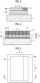
- FIG. 13 and 14 A configuration of an ultrasound probe according to Embodiment 2 are shown in Figs. 13 and 14 .
- This ultrasound probe is different from the ultrasound probe of Embodiment 1 shown in Figs. 1 and 2 in that the plurality of third conductive parts 32 are electrically connected to each other by joining a fourth conductive part 11 extending in the arrangement direction X over the plurality of piezoelectric elements 2 to side surfaces of the plurality of third conductive parts 32 in the elevation direction instead of filling the gaps between the third conductive parts 32 of the acoustic matching parts 3 adjacent to each other with the conductive fillers 5.
- a commonization conductive part 12 which is over the plurality of piezoelectric elements 2 and has a single-layer structure in the lamination direction of the laminates constituting the piezoelectric element 2 is formed by the plurality of third conductive parts 32 and the fourth conductive part 11.
- a common electrode common to the plurality of piezoelectric elements 2 is formed by the second conductive parts 23 of the plurality of piezoelectric elements 2 and the commonization conductive part 12.
- the insulating fillers 4A fill between the piezoelectric elements 2 adjacent to each other and between the acoustic matching parts 3 adjacent to each other, and thus, the positions of the plurality of piezoelectric elements 2 and the positions of the plurality of acoustic matching parts 3 are fixed.
- the ultrasound probe of Embodiment 2 can be manufactured in a such a manner that the plurality of composite laminates 9 arranged in an array along the arrangement direction X is formed by dicing the layers in a state in which the second conductive layer 123 is covered by the acoustic matching layer 131 and the third conductive layer 132 as shown in Figs. 5 to 7 , the insulating fillers 4A fill the gaps between the composite laminates 9 adjacent to each other, and the fourth conductive part 11 extending in the arrangement direction X over the plurality of piezoelectric elements 2 is joined to the side surfaces of the plurality of third conductive parts 32 in the elevation direction.
- the plurality of piezoelectric elements 2 is protected from being damaged due to the dicing, and thus, it is possible to prevent the sensitivity from being degraded even though the pitch P1 between the piezoelectric elements 2 is small.
- the fourth conductive part 11 can be formed by applying the conductive paste in a strip shape which spreads over the plurality of piezoelectric elements 2 and extends in the arrangement direction X to the side surfaces of the plurality of third conductive parts 32 in the elevation direction and hardening the conductive paste through heating.
- a thickness of the commonization conductive part 12 having a single-layer structure that is, the thickness of the third conductive part 32 has a value of substantially 1/4 of an average wavelength in a case where an ultrasound having a resonance frequency of the piezoelectric body part 21 propagates through the third conductive part 32 in order to satisfy the resonance condition.
- the thickness of the commonization conductive part 12 having the single-layer structure that is, the thickness of the third conductive part 32 of the acoustic matching part 3 and the thickness of the main part 31 of the acoustic matching part 3 have values which are substantially equal to each other in order for all the acoustic matching parts 3 to easily satisfy the resonance condition.
- the insulation part 10 can be arranged on the third conductive parts 32, and thus, a layer structure in which the acoustic impedances gradually decrease from the piezoelectric element 2 to the test subject.
- the third conductive parts 32 of the acoustic matching part 3 are respectively arranged on upper surfaces of both end portions of the second conductive part 23 of the piezoelectric element 2 in the elevation direction Y, and the commonization conductive parts 12 having the single-layer structure can be formed on both the end portions of the piezoelectric element 2 in the elevation direction Y. Accordingly, the upper surfaces of both the end portions of the second conductive part 23 in the elevation direction Y are covered by the third conductive parts 32, and the impact resistance of the plurality of piezoelectric elements 2 is improved.
- the main part 31 and both the third conductive parts 32 can be configured such that transmission sound pressure and reception sound pressure at both the third conductive parts 32 are lower than those at the main part 31 of the acoustic matching part 3, and thus, the ultrasound beam is focused in the elevation direction Y. Accordingly, it is possible to generate an ultrasound image having higher definition.
- both the third conductive parts 32 have the sizes equal to each other, and have the acoustic impedances equal to each other. Accordingly, it is possible to focus the ultrasound beam with higher accuracy in the elevation direction Y.
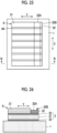
- FIG. 16 and 17 A configuration of an ultrasound probe according to Embodiment 3 are shown in Figs. 16 and 17 .
- This ultrasound probe is different from the ultrasound probe of Embodiment 2 shown in Figs. 13 and 14 in that the plurality of third conductive parts 32 is electrically connected to each other by joining a fourth conductive part 13 which spreads over the plurality of piezoelectric elements 2 and extends in the arrangement direction X to upper surfaces of the plurality of third conductive parts 32, that is, surfaces of the plurality of third conductive parts 32 in the lamination direction of the laminates constituting the piezoelectric element 2 instead of joining the fourth conductive part 11 to the side surfaces of the plurality of third conductive parts 32 in the elevation direction.
- a commonization conductive part 14 which spreads over the plurality of piezoelectric elements 2 and has a structure in which two layers are laminated in the lamination direction of the laminates constituting the piezoelectric element 2 is formed by the plurality of third conductive parts 32 and the fourth conductive part 13.
- the common electrode common to the plurality of piezoelectric elements 2 is formed by the second conductive parts 23 of the plurality of piezoelectric elements 2 and the commonization conductive part 14.
- the ultrasound probe of Embodiment 3 can be manufactured as shown in Fig. 17 in such a manner that the plurality of composite laminates 9 arranged in an array along the arrangement direction X is formed by dicing the layers in a state in which the second conductive layer 123 is covered by the acoustic matching layer 131 and the third conductive layer 132 as shown in Figs. 5 to 7 , the insulating fillers 4A fill the gaps between the composite laminates 9 adjacent to each other as shown in Figs. 19 and 20 , and the fourth conductive part 13 extending in the arrangement direction X over the plurality of piezoelectric elements 2 is joined to the upper surfaces of the plurality of third conductive parts 32.
- the plurality of piezoelectric elements 2 is protected from being damaged due to the dicing, and thus, it is possible to prevent the sensitivity from being degraded even though the pitch P1 between the piezoelectric elements 2 is small.
- the fourth conductive part 13 can be formed by applying a conductive paste acquired by dispersing conductive particles in an insulating material such as a resin on the upper surfaces of the plurality of third conductive parts 32 and hardening the conductive paste through heating.
- the fourth conductive part 13 arranged on the upper surfaces of the plurality of third conductive parts 32 has an acoustic impedance which is lower than the acoustic impedance of the third conductive part 32 and is higher than the acoustic impedance of the test subject.
- the thickness of the third conductive part 32 has a value of substantially 1/4 of the average wavelength in a case where an ultrasound having a resonance frequency of the piezoelectric body part 21 propagates through the third conductive part 32 and the thickness of the fourth conductive part 13 has a value of substantially 1/4 of an average wavelength in a case where the ultrasound having the resonance frequency of the piezoelectric body part 21 propagates through the third conductive part 32 in order to satisfy the resonance condition.
- the entire thickness of the commonization conductive part 14 having the two-layer structure has a value of substantially 1/4 of an average wavelength in a case where the ultrasound having the resonance frequency of the piezoelectric body part 21 propagates through the commonization conductive part 14 in order to satisfy the resonance condition.
- the entire thickness of the commonization conductive part 14 having the two-layer structure and the thickness of the main part 31 of the acoustic matching part 3 have values which are substantially equal to each other in order for all the acoustic matching parts 3 to easily satisfy the resonance condition.
- the insulation part 10 can be arranged on the fourth conductive part 13.
- the insulation part 10 is made of an insulating material having an acoustic impedance which is lower than the acoustic impedance of the fourth conductive part 13 and is higher than the acoustic impedance of the test subject, a layer structure in which the acoustic impedances gradually decrease from the piezoelectric element 2 to the test subject can be formed.
- the third conductive part 32 can be made of a high-concentration Ag (silver) paste having an acoustic impedance of 14.8 Mrayl
- the fourth conductive part 13 can be made of a relatively-low-concentration Ag paste having an acoustic impedance of 4.25 Mrayl
- the insulation part 10 can be made of a resin material such as an epoxy resin having an acoustic impedance of 1.85 Mrayl.
- 1 Mrayl 10 6 kg ⁇ m -2 ⁇ s -1 .
- the fourth conductive part 13 can be made of a conductive paste acquired by dispersing Cu (copper), Fe (iron), Ni (nickel), Al (aluminum), C (carbon) particles having a density lower than a density of the Ag in an insulating material.
- the third conductive part 32 can be constituted by a plurality of conductive layers laminated in the lamination direction of the laminates constituting the piezoelectric element 2.
- the third conductive part 32 has a lamination structure in which two layers including a first layer 321 joined to the upper surface of the second conductive part 23 of the piezoelectric element 2 and a second layer 322 joined to the upper surface of the first layer 321 are laminated.
- the third conductive part 32 has the lamination structure in which the plurality of layers is laminated in this manner, and thus, a layer structure in which the acoustic impedances smoothly decrease from the piezoelectric element 2 to the test subject is formed. Accordingly, it is possible to transmit and receive the ultrasound with higher efficiency.
- the first layer 321 of the third conductive part 32 can be made of a high-density medium paste having an acoustic impedance of 20.6 Mrayl
- the second layer 322 of the third conductive part 32 can be made of a high-concentration Ag paste having an acoustic impedance of 7.51 Mrayl
- the fourth conductive part 13 can be made of a relatively-low-concentration Ag paste having an acoustic impedance of 2.74 Mrayl
- the insulation part 10 can be made of a resin material such as an epoxy resin having an acoustic impedance of 1.66 Mrayl.
- a conductive paste acquired by dispersing noble particles such as Au or Pt (platinum) in an insulating material such as a resin can be used as the high-density medium paste which is the material for forming the first layer 321 of the third conductive part 32.
- the fourth conductive part 13 can be made of a conductive paste acquired by dispersing Cu, Fe, Ni, Al, or C particles having a density lower than the density of the Ag in an insulating material such as a resin.
- the third conductive part 32 can be made of a high-density medium paste having an acoustic impedance of 20.6 Mrayl
- the fourth conductive part 13 can have a lamination structure in which two layers including a first layer which is joined to the third conductive part 32 and is made of a high-concentration Ag paste having an acoustic impedance of 7.51 Mrayl and a second layer which is joined to the first layer and is made of a relatively-low-concentration Ag paste having an acoustic impedance of 2.74 Mrayl
- the insulation part 10 can be made of a resin material such as an epoxy resin having an acoustic impedance of 1.66 Mrayl.
- the fourth conductive part 13 having a lamination structure of a plurality of layers can be formed on the third conductive part 32 having a lamination structure of a plurality of layers.
- the third conductive parts 32 of the acoustic matching part 3 can be respectively arranged on the upper surfaces of both the end portions of the second conductive part 23 of the piezoelectric element 2 in the elevation direction Y, and the commonization conductive parts 14 having the two-layer structure can be respectively formed on both the end portions of the piezoelectric element 2 in the elevation direction Y. Accordingly, the upper surfaces of both the end portions of the second conductive part 23 in the elevation direction Y are covered by the commonization conductive part 14, and the impact resistance of the plurality of piezoelectric elements 2 is improved.
- the main part 31 and both the commonization conductive parts 14 can be configured such that transmission sound pressure and reception sound pressure at both the commonization conductive parts 14 are lower than those at the main part 31 of the acoustic matching part 3, and thus, the ultrasound beam is focused in the elevation direction Y Accordingly, it is possible to generate an ultrasound image having higher definition.
- the commonization conductive parts 14 at both the end portions in the elevation direction Y have the sizes equal to each other, and have the acoustic impedances equal to each other. Accordingly, it is possible to focus the ultrasound beam in the elevation direction Y with higher accuracy.
- FIG. 23 and 24 A configuration of an ultrasound probe according to Embodiment 4 are shown in Figs. 23 and 24 .
- This ultrasound probe is different from the ultrasound probe of Embodiment 3 shown in Figs. 16 and 17 in that each of the plurality of third conductive parts 32 has a cut-out part 32A extending in the arrangement direction X and the plurality of third conductive parts 32 is electrically connected to each other by joining the fourth conductive part 13 extending in the arrangement direction X over the plurality of piezoelectric elements 2 on the cut-out parts 32A of the plurality of third conductive parts 32.
- the cut-out part 32A is cut such that a wall part 32B protruding in the lamination direction of the laminates constituting the piezoelectric element 2 is formed at an end portion of the third conductive part 32 in the elevation direction Y
- the commonization conductive part 14 which spreads over the plurality of piezoelectric elements 2 and has a structure in which two layers are laminated in the lamination direction of the laminates constituting the piezoelectric element 2 is formed by the plurality of third conductive parts 32 and the fourth conductive part 13, and the common electrode common to the plurality of piezoelectric elements 2 is formed by the second conductive parts 23 of the plurality of piezoelectric elements 2 and the commonization conductive part 14.
- the ultrasound probe of Embodiment 4 can be manufactured as shown in Fig. 24 in such a manner that the plurality of composite laminates 9 arranged in an array along the arrangement direction X is formed by dicing the layers in a state in which the second conductive layer 123 is covered by the acoustic matching layer 131 and the third conductive layer 132 as shown in Figs. 5 to 7 , the insulating fillers 4A fill the gaps between the composite laminates 9 adjacent to each other as shown in Figs.
- the cut-out parts 32A extending in the arrangement direction X are formed in the upper surfaces of the plurality of third conductive parts 32
- the wall part 32B is formed at the end portion of each of the third conductive parts 32 in the elevation direction Y
- the fourth conductive part 13 extending in the arrangement direction X over the plurality of piezoelectric elements 2 is joined to the cut-out parts 32A of the plurality of third conductive parts 32.
- the plurality of piezoelectric elements 2 is protected from being damaged due to the dicing, and thus, it is possible to prevent the sensitivity from being degraded even though the pitch P1 between the piezoelectric elements 2 is small.
- the cut-out parts 32A of the plurality of third conductive parts 32 can be formed by cutting the upper surfaces of the plurality of third conductive parts 32 in the arrangement direction X multiple number of times by using a cutting tool (not shown) having a set width.
- a cutting tool not shown
- the insulating fillers 4A fills the gaps between the composite laminates 9 adjacent to each other, a cut-out part and a wall part at the end portion in the elevation direction Y are formed at the insulating filler 4A, the cut-out parts 32A of the third conductive parts 32 and the cut-out parts of the insulating fillers 4A extend in the arrangement direction X, and the wall parts 32B of the third conductive parts 32 and the wall parts of the insulating fillers 4A extend in the arrangement direction X.
- the conductive paste is prevent from being dropped toward the piezoelectric element 2 from the end portion in the elevation direction Y by the wall parts 32B of the third conductive parts 32 and the wall parts of the insulating fillers 4A extending in the arrangement direction X. Accordingly, the common electrode can be prevented from short-circuiting the first conductive part 22 of the piezoelectric element 2 due to the liquid dropping of the conductive paste.
- the cut-out parts 32A are formed on the upper surfaces of the plurality of third conductive parts 32, even though the upper surfaces of the third conductive parts 32 are deteriorated or contaminants adhere to the upper surfaces of the third conductive parts 32, these deteriorated portions and contaminants are removed at the time of forming the cut-out parts 32A, and the surfaces of the cut-out parts 32A are activated. Thus, electrical connectivity and joining ability of the fourth conductive part 13 to the third conductive parts 32 are improved, and thus, a high-reliability ultrasound probe is realized.
- one of the third conductive part 32 and the fourth conductive part 13 or both the third conductive part 32 and the fourth conductive part 13 can also have the lamination structure in which the plurality of layers is laminated in Embodiment 4.
- the insulation part 10 can be arranged on the fourth conductive part 13.
- the third conductive parts 32 of the acoustic matching part 3 can be respectively arranged on the upper surfaces of both the end portions of the second conductive part 23 of the piezoelectric element 2 in the elevation direction Y, and the commonization conductive parts 14 having the two-layer structure can be respectively formed at both the end portions of the piezoelectric element 2 in the elevation direction Y.
- FIG. 27 and 28 A configuration of an ultrasound probe according to Embodiment 5 are shown in Figs. 27 and 28 .
- This ultrasound probe is different from the ultrasound probe of Embodiment 3 shown in Figs. 16 and 17 in that grooves 32C extending in the arrangement direction X are respectively formed in the plurality of third conductive parts 32 and the plurality of third conductive parts 32 are electrically connected to each other by joining the fourth conductive part 13 extending in the arrangement direction X over the plurality of piezoelectric elements 2 to the grooves 32C of the plurality of third conductive parts 32.
- the commonization conductive part 14 which spreads over the plurality of piezoelectric elements 2 and has the structure in which the two layers are laminated in the lamination direction of the laminates constituting the piezoelectric element 2 is formed by the plurality of third conductive parts 32 and the fourth conductive part 13, and the common electrode common to the plurality of piezoelectric elements 2 is formed by the second conductive parts 23 of the plurality of piezoelectric elements 2 and the commonization conductive part 14.
- the ultrasound probe of Embodiment 5 can be manufactured in such a manner that the plurality of composite laminates 9 arranged in an array along the arrangement direction X is formed by dicing the layers in a state in which the second conductive layer 123 is covered by the acoustic matching layer 131 and the third conductive layer 132 as shown in Figs. 5 to 7 , the insulating fillers 4A fill the gaps between the composite laminates 9 adjacent to each other as shown in Figs.
- the grooves 32C extending in the arrangement direction X are formed in the upper surfaces of the plurality of third conductive parts 32, and the fourth conductive part 13 extending in the arrangement direction X over the plurality of piezoelectric elements 2 is joined within the grooves 32C of the plurality of third conductive parts 32.
- the plurality of piezoelectric elements 2 is protected from being damaged due to the dicing, and thus, it is possible to prevent the sensitivity from being degraded even though the pitch P1 between the piezoelectric elements 2 is small.
- the grooves 32C of the plurality of third conductive parts 32 can be formed by cutting the upper surfaces of the plurality of third conductive parts 32 in the arrangement direction X at least one time by using a cutting tool (not shown) having a set width.
- a cutting tool not shown having a set width.
- Grooves are also formed in the insulating fillers 4A filling the gaps between the composite laminates 9 adjacent to each other at the time of forming the grooves 32C, and the grooves 32C of the third conductive parts 32 and the grooves of the insulating fillers 4A extend in the arrangement direction X.
- the conductive paste is applied to the grooves 32C of the third conductive parts 32 and the grooves of the insulating fillers 4A at the time of forming the fourth conductive part 13, the conductive paste is prevented from being dropped toward the piezoelectric element 2 from the end portion in the elevation direction Y. Accordingly, the common electrode can be prevented from short-circuiting the first conductive part 22 of the piezoelectric element 2 due to the liquid dropping of the conductive paste.
- the grooves 32C are formed in the upper surfaces of the plurality of third conductive parts 32, even though the upper surfaces of the third conductive parts 32 are deteriorated or contaminants adhere to the upper surfaces of the third conductive parts 32, these deteriorated portions and the contaminants are removed at the time of forming the grooves 32C, and the inner wall surfaces of the grooves 32C are activated. Thus, electrical connectivity and joining ability of the fourth conductive part 13 to the third conductive parts 32 are improved, and thus, a high-reliability ultrasound probe is realized.
- one of the third conductive part 32 and the fourth conductive part 13 or both the third conductive part 32 and the fourth conductive part 13 can also have the lamination structure in which the plurality of layers is laminated in Embodiment 5.
- the insulation part 10 can be arranged on the fourth conductive part 13.
- the third conductive parts 32 of the acoustic matching part 3 can be respectively arranged on the upper surfaces of both the end portions of the second conductive part 23 of the piezoelectric element 2 in the elevation direction Y, and the commonization conductive parts 14 having the two-layer structure can be respectively formed at both the end portions of the piezoelectric element 2 in the elevation direction Y.
- the conductive paste acquired by dispersing the conductive particles in the insulating material is used for forming the third conductive parts 32 and the fourth conductive parts 6, 11, and 13
- particles having various shapes such as a spherical shape, a flake shape (thin piece shape), and a dendrite shape having a plurality of protrusions can be used as the conductive particles.
- Au, Pt, Ag, Cu, Fe-Pt, C (including carbon and graphite), Ni, or Al can be used as the material of the conductive particles.
- Low-melting-point glass can be used as the insulating material for dispersing the conductive particles in addition to resin materials such as an epoxy resin, a urethane resin, an acrylic resin, a silicone resin, and a polyimide resin.
- resin materials such as an epoxy resin, a urethane resin, an acrylic resin, a silicone resin, and a polyimide resin.
- the third conductive parts 32 and the fourth conductive parts 11 and 13 other than the fourth conductive part 6 constituted by the plurality of conductive fillers 5 can be formed by using the conductive material such as Au, Pt, Ag, Ti (titanium), Cu, Cr (chromium), C, Ni, or Al by a sputter deposition method, a thermal evaporation method, an electrolytic plating method, an electroless plating method, or a baking method instead of applying and hardening the conductive paste.
- the conductive material such as Au, Pt, Ag, Ti (titanium), Cu, Cr (chromium), C, Ni, or Al by a sputter deposition method, a thermal evaporation method, an electrolytic plating method, an electroless plating method, or a baking method instead of applying and hardening the conductive paste.
- a conductive sheet including a rod-shaped conductor can be used as the material for forming the third conductive parts 32 and the fourth conductive parts 11 and 13.
Landscapes
- Engineering & Computer Science (AREA)
- Health & Medical Sciences (AREA)
- Life Sciences & Earth Sciences (AREA)
- Physics & Mathematics (AREA)
- Acoustics & Sound (AREA)
- Signal Processing (AREA)
- Mechanical Engineering (AREA)
- Biomedical Technology (AREA)
- Surgery (AREA)
- Radiology & Medical Imaging (AREA)
- Nuclear Medicine, Radiotherapy & Molecular Imaging (AREA)
- Heart & Thoracic Surgery (AREA)
- Medical Informatics (AREA)
- Molecular Biology (AREA)
- Pathology (AREA)
- Animal Behavior & Ethology (AREA)
- General Health & Medical Sciences (AREA)
- Public Health (AREA)
- Veterinary Medicine (AREA)
- Biophysics (AREA)
- Manufacturing & Machinery (AREA)
- Transducers For Ultrasonic Waves (AREA)
- Ultra Sonic Daignosis Equipment (AREA)
Claims (22)
- Ultraschallsonde, umfassend:mehrere piezoelektrische Elemente (2) auf einem Trägermaterial (1), die in einem Array entlang einer Anordnungsrichtung (X) angeordnet sind,wobei jedes der mehreren piezoelektrischen Elemente (2) ein Laminat enthält, bei dem ein erster leitfähiger Teil (22), ein piezoelektrischer Körperteil (21) und ein zweiter leitfähiger Teil (23) auf einer Oberfläche des Trägermaterials (1) in einer Laminierrichtung, die die Anordnungsrichtung (X) kreuzt, der Reihe nach laminiert sind;mehrere akustische Anpassungsteile (3), die jeweils auf den zweiten leitfähigen Teilen (23) der mehreren piezoelektrischen Elemente (2) angeordnet sind, vorgesehen sind, mehrere dritte leitfähige Teile (32), die jeweils einen Endabschnitt der mehreren akustischen Anpassungsteile (3) in einer Höhenrichtung (Y), die die Anordnungsrichtung (X) und die Laminierrichtung kreuzt, mit den zweiten leitfähigen Teilen (23) der mehreren piezoelektrischen Elemente (2) verbinden, vorgesehen sind, wobei die akustischen Anpassungsteile (3) und die dritten leitfähigen Teile (32) in der Höhenrichtung zueinander benachbart sind,ein vierter leitfähiger Teil (6, 11, 13) vorgesehen ist, der die mehreren dritten leitfähigen Teile (32) miteinander elektrisch verbindet, unddie zweiten leitfähigen Teile (23) der mehreren piezoelektrischen Elemente (2), die mehreren dritten leitfähigen Teile (32) und der vierte leitfähige Teil (6, 11, 13) eine gemeinsame Elektrode, die den mehreren piezoelektrischen Elementen (2) gemeinsam ist, bilden.
- Ultraschallsonde nach Anspruch 1,
wobei die mehreren dritten leitfähigen Teile und der vierte leitfähige Teil einen leitfähigen Standardisierungsteil bilden, der sich über die mehreren piezoelektrischen Elemente erstreckt und eine einschichtige Struktur in der Laminierrichtung aufweist. - Ultraschallsonde nach Anspruch 2,
wobei der vierte leitfähige Teil aus mehreren leitfähigen Füllstoffen, die zwischen den mehreren dritten leitfähigen Teilen in der Anordnungsrichtung füllen, aufgebaut ist. - Ultraschallsonde nach Anspruch 2,
wobei sich der vierte leitfähige Teil in der Anordnungsrichtung über die mehreren piezoelektrischen Elemente erstreckt und mit Seitenflächen der mehreren dritten leitfähigen Teile in der Höhenrichtung verbunden ist. - Ultraschallsonde nach Anspruch 1,
wobei die mehreren dritten leitfähigen Teile und der vierte leitfähige Teil einen leitfähigen Standardisierungsteil bilden, der sich über die mehreren piezoelektrischen Elemente erstreckt und eine Struktur aufweist, bei der mehrere Schichten in der Laminierrichtung laminiert sind. - Ultraschallsonde nach Anspruch 5,
wobei sich der vierte leitfähige Teil in der Anordnungsrichtung über die mehreren piezoelektrischen Elemente erstreckt und mit Fläche der mehreren dritten leitfähigen Teile in der Laminierrichtung verbunden ist. - Ultraschallsonde nach Anspruch 6,wobei jeder der mehreren dritten leitfähigen Teile einen ausgeschnittenen Teil enthält, der so geschnitten ist, dass ein Wandteil, der in der Laminierrichtung vorsteht, an einem Endabschnitt in der Höhenrichtung gebildet wird, undder vierte leitfähige Teil auf den ausgeschnittenen Teilen der mehreren dritten leitfähigen Teile angeordnet ist.
- Ultraschallsonde nach Anspruch 6,wobei jedes der mehreren dritten leitfähigen Teile eine Nut, die sich in der Anordnungsrichtung erstreckt, enthält, undder vierte leitfähige Teil innerhalb der Nuten der mehreren dritten leitfähigen Teile angeordnet ist.
- Ultraschallsonde nach einem der Ansprüche 6 bis 8,
wobei der vierte leitfähige Teil eine Laminierungsstruktur, bei der mehrere Schichten in der Laminierrichtung laminiert sind, aufweist. - Ultraschallsonde nach einem der Ansprüche 6 bis 9,
wobei der dritte leitfähige Teil eine akustische Impedanz, die höher als eine akustische Impedanz des vierten leitfähigen Teils ist, aufweist. - Ultraschallsonde nach einem der Ansprüche 6 bis 10,
wobei in der Laminierrichtung eine Dicke des dritten leitfähigen Teils einen Wert von im Wesentlichen 1/4 einer Wellenlänge in einem Fall, in dem sich ein Ultraschall mit einer Resonanzfrequenz des piezoelektrischen Körperteils durch den dritten leitfähigen Teil verbreitet, aufweist und eine Dicke des vierten leitfähigen Teils einen Wert von im Wesentlichen 1/4 einer Wellenlänge in einem Fall, in dem sich der Ultraschall mit der Resonanzfrequenz des piezoelektrischen Körperteils durch den vierten leitfähigen Teil verbreitet, aufweist. - Ultraschallsonde nach einem der Ansprüche 2 bis 10,
wobei in der Laminierrichtung eine Dicke des leitfähigen Standardisierungsteils einen Wert von im Wesentlichen 1/4 einer Durchschnittswellenlänge in einem Fall, in dem sich ein Ultraschall mit einer Resonanzfrequenz des piezoelektrischen Körperteils durch den leitfähigen Standardisierungsteil verbreitet, aufweist. - Ultraschallsonde nach einem der Ansprüche 2 bis 12,
wobei der dritte leitfähige Teil eine Laminierungsstruktur, bei der mehrere Schichten in der Laminierrichtung laminiert sind, aufweist. - Ultraschallsonde nach einem der Ansprüche 2 bis 13,wobei ferner ein Isolationsteil auf dem leitfähigen Standardisierungsteil so angeordnet ist, dass er den mehreren piezoelektrischen Elementen entspricht, undwobei der Isolationsteil eine akustische Impedanz, die geringer als eine akustische Impedanz des leitfähigen Standardisierungsteils ist, aufweist.
- Ultraschallsonde nach Anspruch 14,
wobei in der Laminierrichtung eine Dicke des leitfähigen Standardisierungsteils und eine Dicke des Isolationsteils jeweils einen Wert von im Wesentlichen 1/4 einer Durchschnittswellenlänge in einem Fall, in dem sich ein Ultraschall mit einer Resonanzfrequenz des piezoelektrischen Körperteils durch den leitfähigen Standardisierungsteil verbreitet, aufweist. - Ultraschallsonde nach einem der Ansprüche 2 bis 15,
wobei leifähige Standardisierungsteile jeweils an beiden Endabschnitten des zweiten leitfähigen Teils von jedem der mehreren piezoelektrischen Elemente in der Höhenrichtung angeordnet sind. - Ultraschallsonde nach Anspruch 16,
wobei die leitfähigen Standardisierungsteile, die jeweils an den beiden Endabschnitten des zweiten leitfähigen Teils von jedem der mehreren piezoelektrischen Elemente in der Höhenrichtung angeordnet sind, Größen, die einander gleich sind, und akustische Impedanzen, die einander gleich sind, aufweisen. - Ultraschallsonde nach einem der Ansprüche 2 bis 17,
wobei in der Laminierrichtung eine Dicke des leitfähigen Standardisierungsteils und eine Dicke eines Abschnitts des akustischen Anpassungsteils, der von dem dritten leitfähigen Teil verschieden ist, Werte aufweisen, die im Wesentlichen einander gleich sind. - Verfahren des Herstellens einer Ultraschallsonde, die mehrere piezoelektrische Elemente (2) auf einem Trägermaterial, das in einem Array entlang einer Anordnungsrichtung (X) angeordnet ist, enthält, wobei das Verfahren umfasst:einen ersten Schritt des Laminierens einer ersten leitfähigen Schicht (122), einer piezoelektrischen Körperschicht (121) und einer zweiten leitfähigen Schicht (123) der Reihe nach auf einer Oberfläche des Trägermaterials (1) in einer Laminierrichtung, die die Anordnungsrichtung (X) kreuzt;einen zweiten Schritt des Bildens einer akustischen Anpassungsschicht (131) und einer dritten leitfähigen Schicht (132), die sich in der Anordnungsrichtung (X) auf einer Oberfläche der zweiten leitfähigen Schicht (123) erstrecken, wobei die dritte leitfähige Schicht (132) an einem Endabschnitt der akustischen Anpassungsschicht (131) in einer Höhenrichtung (Y), die die Anordnungsrichtung (X) und die Laminierrichtung kreuzt, gebildet ist und die akustische Anpassungsschicht (131) und die dritte leitfähige Schicht (132) in der Höhenrichtung benachbart zueinander gebildet sind,einen dritten Schritt des Bildens von mehreren zusammengesetzten Laminate, die in der Anordnungsrichtung (X) voneinander getrennt sind, durch Würfeln des ersten leitfähigen Schicht (122), der piezoelektrischen Körperschicht (121), der zweiten leitfähigen Schicht (123), der akustischen Anpassungsschicht (131) und der dritten leitfähigen Schicht (132) mit einem eingestellten Abstand (P1) entlang der Höhenrichtung (Y); undeinen vierten Schritt des Bildens eines vierten leitfähigen Teils (6, 11, 13), der die dritten leitfähigen Schichten (132) der mehreren zusammengesetzten Laminate, die voneinander getrennt sind, elektrisch miteinander verbindet,wobei eine gemeinsame Elektrode, die den mehreren piezoelektrischen Elementen (2) gemeinsam ist, gebildet wird, indem die zweiten leitfähigen Schichten und die dritten leitfähigen Schichten der mehreren zusammengesetzten Laminate und der vierte leitfähige Teil verwendet werden.
- Verfahren des Herstellens einer Ultraschallsonde nach Anspruch 19,
wobei der vierte leitfähige Teil durch Befüllen von Räumen zwischen den dritten leitfähigen Schichten der mehreren zusammengesetzten Laminate in der Anordnungsrichtung mit leitfähigen Füllstoffen gebildet ist. - Verfahren des Herstellens einer Ultraschallsonde nach Anspruch 19,
wobei sich der vierte leitfähige Teil in der Anordnungsrichtung über die mehreren piezoelektrischen Elemente erstreckt und mit den dritten leitfähigen Schichten der mehreren zusammengesetzten Laminate verbunden ist. - Verfahren des Herstellens einer Ultraschallsonde nach einem der Ansprüche 19 bis 21, ferner umfassend:
einen Schritt des Befüllens von Räumen zwischen den mehreren zusammengesetzten Laminaten mit isolierenden Füllstoffen.
Applications Claiming Priority (3)
| Application Number | Priority Date | Filing Date | Title |
|---|---|---|---|
| JP2016201981 | 2016-10-13 | ||
| JP2016236599 | 2016-12-06 | ||
| PCT/JP2017/032679 WO2018070159A1 (ja) | 2016-10-13 | 2017-09-11 | 超音波探触子および超音波探触子の製造方法 |
Publications (3)
| Publication Number | Publication Date |
|---|---|
| EP3528511A1 EP3528511A1 (de) | 2019-08-21 |
| EP3528511A4 EP3528511A4 (de) | 2019-10-09 |
| EP3528511B1 true EP3528511B1 (de) | 2025-01-08 |
Family
ID=61905265
Family Applications (1)
| Application Number | Title | Priority Date | Filing Date |
|---|---|---|---|
| EP17860917.8A Active EP3528511B1 (de) | 2016-10-13 | 2017-09-11 | Ultraschallsonde und verfahren zur herstellung der ultraschallsonde |
Country Status (5)
| Country | Link |
|---|---|
| US (1) | US11197655B2 (de) |
| EP (1) | EP3528511B1 (de) |
| JP (1) | JP6663031B2 (de) |
| CN (1) | CN109804643B (de) |
| WO (1) | WO2018070159A1 (de) |
Families Citing this family (9)
| Publication number | Priority date | Publication date | Assignee | Title |
|---|---|---|---|---|
| KR102803133B1 (ko) * | 2017-02-23 | 2025-05-07 | 삼성메디슨 주식회사 | 초음파 프로브 |
| JP7108816B2 (ja) * | 2017-06-30 | 2022-07-29 | パナソニックIpマネジメント株式会社 | 音響整合層 |
| CN110227640B (zh) * | 2019-06-18 | 2021-01-26 | 京东方科技集团股份有限公司 | 压电传感器组件及其制作方法以及显示面板 |
| CN112438753B (zh) * | 2019-09-05 | 2026-01-02 | 深圳迈瑞生物医疗电子股份有限公司 | 超声探头的声头及超声探头 |
| CN110721891B (zh) * | 2019-10-29 | 2021-11-05 | 深圳市索诺瑞科技有限公司 | 一种超声换能器加工方法 |
| JP7573192B2 (ja) * | 2020-04-03 | 2024-10-25 | パナソニックIpマネジメント株式会社 | 超音波送受波器並びに超音波流量計、超音波流速計、超音波濃度計、及び製造方法 |
| CN113171117B (zh) * | 2021-03-29 | 2022-12-23 | 聚融医疗科技(杭州)有限公司 | 一种在使用过程中阵元间距可调探头及其制备方法 |
| WO2022209772A1 (ja) | 2021-04-01 | 2022-10-06 | 富士フイルム株式会社 | 超音波プローブ、超音波診断装置、及び超音波プローブの製造方法 |
| CN119184735A (zh) * | 2023-06-25 | 2024-12-27 | 华为技术有限公司 | 超声传感器及其制造方法、超声检测设备 |
Citations (2)
| Publication number | Priority date | Publication date | Assignee | Title |
|---|---|---|---|---|
| EP0142318A2 (de) * | 1983-11-09 | 1985-05-22 | Matsushita Electric Industrial Co., Ltd. | Ultraschallwandler |
| CN104586430A (zh) * | 2015-01-19 | 2015-05-06 | 深圳市理邦精密仪器股份有限公司 | 超声探头及其制造方法 |
Family Cites Families (22)
| Publication number | Priority date | Publication date | Assignee | Title |
|---|---|---|---|---|
| US4571520A (en) * | 1983-06-07 | 1986-02-18 | Matsushita Electric Industrial Co. Ltd. | Ultrasonic probe having a backing member of microballoons in urethane rubber or thermosetting resin |
| JPH03162839A (ja) * | 1989-11-21 | 1991-07-12 | Olympus Optical Co Ltd | 超音波探触子 |
| US5176140A (en) | 1989-08-14 | 1993-01-05 | Olympus Optical Co., Ltd. | Ultrasonic probe |
| JP3469386B2 (ja) | 1996-02-07 | 2003-11-25 | 株式会社東芝 | 超音波トランスジューサ及びその製造方法 |
| US6822374B1 (en) * | 2000-11-15 | 2004-11-23 | General Electric Company | Multilayer piezoelectric structure with uniform electric field |
| JP2003230194A (ja) * | 2002-12-20 | 2003-08-15 | Matsushita Electric Ind Co Ltd | 超音波探触子 |
| JP2005340903A (ja) * | 2004-05-24 | 2005-12-08 | Olympus Corp | 超音波トランスデューサとその製造方法 |
| JP4426513B2 (ja) * | 2005-07-27 | 2010-03-03 | アロカ株式会社 | 超音波探触子及びその製造方法 |
| EP2014236A4 (de) * | 2006-04-28 | 2016-05-11 | Konica Minolta Inc | Ultraschallsonde |
| JP4171038B2 (ja) * | 2006-10-31 | 2008-10-22 | 株式会社東芝 | 超音波プローブおよび超音波診断装置 |
| WO2008056611A1 (en) * | 2006-11-08 | 2008-05-15 | Panasonic Corporation | Ultrasound probe |
| JP4933392B2 (ja) * | 2007-04-02 | 2012-05-16 | 富士フイルム株式会社 | 超音波探触子及びその製造方法 |
| US7969068B2 (en) | 2007-12-19 | 2011-06-28 | Ueda Japan Radio Co., Ltd. | Ultrasonic transducer with a retracted portion on a side surface of the piezoelectric layer |
| JP5079485B2 (ja) * | 2007-12-19 | 2012-11-21 | 上田日本無線株式会社 | 超音波探触子及びその製造方法 |
| JP5132333B2 (ja) * | 2008-01-22 | 2013-01-30 | 株式会社東芝 | 超音波探触子及び超音波探触子の製造方法 |
| KR101737517B1 (ko) | 2009-10-26 | 2017-05-19 | 삼성전자주식회사 | 보조도어를 구비한 냉장고 및 보조도어 제조방법 |
| JP2012114713A (ja) | 2010-11-25 | 2012-06-14 | Toshiba Corp | 超音波プローブ |
| JP5738671B2 (ja) * | 2011-05-18 | 2015-06-24 | 株式会社東芝 | 超音波トランスデューサ、超音波プローブおよび超音波トランスデューサの製造方法 |
| JP5997796B2 (ja) * | 2015-02-27 | 2016-09-28 | 株式会社日立製作所 | 超音波振動子ユニット |
| US12383230B2 (en) * | 2018-11-21 | 2025-08-12 | Siemens Medical Solutions Usa, Inc. | Composite acoustic absorber for ultrasound transducer array |
| US10499509B1 (en) * | 2018-12-31 | 2019-12-03 | General Electric Company | Methods and systems for a flexible circuit |
| GB2588218B (en) * | 2019-10-17 | 2021-10-27 | Darkvision Tech Ltd | Acoustic transducer and method of manufacturing |
-
2017
- 2017-09-11 EP EP17860917.8A patent/EP3528511B1/de active Active
- 2017-09-11 WO PCT/JP2017/032679 patent/WO2018070159A1/ja not_active Ceased
- 2017-09-11 JP JP2018544707A patent/JP6663031B2/ja active Active
- 2017-09-11 CN CN201780062881.1A patent/CN109804643B/zh active Active
-
2019
- 2019-04-11 US US16/381,709 patent/US11197655B2/en active Active
Patent Citations (2)
| Publication number | Priority date | Publication date | Assignee | Title |
|---|---|---|---|---|
| EP0142318A2 (de) * | 1983-11-09 | 1985-05-22 | Matsushita Electric Industrial Co., Ltd. | Ultraschallwandler |
| CN104586430A (zh) * | 2015-01-19 | 2015-05-06 | 深圳市理邦精密仪器股份有限公司 | 超声探头及其制造方法 |
Also Published As
| Publication number | Publication date |
|---|---|
| EP3528511A4 (de) | 2019-10-09 |
| EP3528511A1 (de) | 2019-08-21 |
| JPWO2018070159A1 (ja) | 2019-08-08 |
| US20190231310A1 (en) | 2019-08-01 |
| US11197655B2 (en) | 2021-12-14 |
| WO2018070159A1 (ja) | 2018-04-19 |
| CN109804643A (zh) | 2019-05-24 |
| CN109804643B (zh) | 2021-02-19 |
| JP6663031B2 (ja) | 2020-03-11 |
Similar Documents
| Publication | Publication Date | Title |
|---|---|---|
| US11197655B2 (en) | Ultrasound probe and method of manufacturing ultrasound probe | |
| US8319399B2 (en) | Ultrasound probe | |
| JP5318904B2 (ja) | 積層型超音波トランスデューサ及びその製造方法 | |
| US7567016B2 (en) | Multi-dimensional ultrasound transducer array | |
| JP4933392B2 (ja) | 超音波探触子及びその製造方法 | |
| JP5738671B2 (ja) | 超音波トランスデューサ、超音波プローブおよび超音波トランスデューサの製造方法 | |
| JP2009503990A5 (de) | ||
| CN102068276A (zh) | 超声波探头 | |
| EP3538289B1 (de) | Ultraschallwandler | |
| CN113042347A (zh) | 一种阵列超声换能器 | |
| US9839411B2 (en) | Ultrasound diagnostic apparatus probe having laminated piezoelectric layers oriented at different angles | |
| CN101238506A (zh) | 具有聚乙烯第三匹配层的宽带矩阵换能器 | |
| KR101491801B1 (ko) | 초음파 트랜스듀서 및 그 제조방법 | |
| JP2009072349A (ja) | 超音波トランスデューサ及びその製造方法、並びに、超音波探触子 | |
| US20240326093A1 (en) | Ultrasound probe | |
| JP3280677B2 (ja) | 超音波プローブおよびその製造方法 | |
| JPH07312799A (ja) | 超音波探触子とその製造方法 | |
| KR20150073056A (ko) | 초음파 진단장치 및 초음파 진단장치의 제조방법 | |
| US11938514B2 (en) | Curved shape piezoelectric transducer and method for manufacturing the same | |
| JP5530994B2 (ja) | 超音波探触子およびその製造方法 | |
| JP2003230194A (ja) | 超音波探触子 | |
| JP2005296127A (ja) | 超音波プローブ及び超音波診断装置 | |
| EP3545565B1 (de) | 2d-ultraschallwandleranordnung und verfahren zur herstellung davon | |
| JP3353962B2 (ja) | 超音波探触子の製造方法 | |
| JP2024078674A (ja) | 超音波探触子 |
Legal Events
| Date | Code | Title | Description |
|---|---|---|---|
| STAA | Information on the status of an ep patent application or granted ep patent |
Free format text: STATUS: THE INTERNATIONAL PUBLICATION HAS BEEN MADE |
|
| PUAI | Public reference made under article 153(3) epc to a published international application that has entered the european phase |
Free format text: ORIGINAL CODE: 0009012 |
|
| STAA | Information on the status of an ep patent application or granted ep patent |
Free format text: STATUS: REQUEST FOR EXAMINATION WAS MADE |
|
| 17P | Request for examination filed |
Effective date: 20190408 |
|
| AK | Designated contracting states |
Kind code of ref document: A1 Designated state(s): AL AT BE BG CH CY CZ DE DK EE ES FI FR GB GR HR HU IE IS IT LI LT LU LV MC MK MT NL NO PL PT RO RS SE SI SK SM TR |
|
| AX | Request for extension of the european patent |
Extension state: BA ME |
|
| A4 | Supplementary search report drawn up and despatched |
Effective date: 20190906 |
|
| RIC1 | Information provided on ipc code assigned before grant |
Ipc: H04R 17/00 20060101AFI20190902BHEP Ipc: B06B 1/06 20060101ALI20190902BHEP Ipc: H04R 31/00 20060101ALI20190902BHEP Ipc: A61B 8/14 20060101ALI20190902BHEP |
|
| DAV | Request for validation of the european patent (deleted) | ||
| DAX | Request for extension of the european patent (deleted) | ||
| RAP3 | Party data changed (applicant data changed or rights of an application transferred) |
Owner name: FUJIFILM CORPORATION |
|
| STAA | Information on the status of an ep patent application or granted ep patent |
Free format text: STATUS: EXAMINATION IS IN PROGRESS |
|
| 17Q | First examination report despatched |
Effective date: 20210722 |
|
| GRAP | Despatch of communication of intention to grant a patent |
Free format text: ORIGINAL CODE: EPIDOSNIGR1 |
|
| STAA | Information on the status of an ep patent application or granted ep patent |
Free format text: STATUS: GRANT OF PATENT IS INTENDED |
|
| INTG | Intention to grant announced |
Effective date: 20241022 |
|
| GRAS | Grant fee paid |
Free format text: ORIGINAL CODE: EPIDOSNIGR3 |
|
| GRAA | (expected) grant |
Free format text: ORIGINAL CODE: 0009210 |
|
| STAA | Information on the status of an ep patent application or granted ep patent |
Free format text: STATUS: THE PATENT HAS BEEN GRANTED |
|
| AK | Designated contracting states |
Kind code of ref document: B1 Designated state(s): AL AT BE BG CH CY CZ DE DK EE ES FI FR GB GR HR HU IE IS IT LI LT LU LV MC MK MT NL NO PL PT RO RS SE SI SK SM TR |
|
| REG | Reference to a national code |
Ref country code: GB Ref legal event code: FG4D |
|
| REG | Reference to a national code |
Ref country code: CH Ref legal event code: EP |
|
| REG | Reference to a national code |
Ref country code: DE Ref legal event code: R096 Ref document number: 602017087281 Country of ref document: DE |
|
| REG | Reference to a national code |
Ref country code: IE Ref legal event code: FG4D |
|
| P01 | Opt-out of the competence of the unified patent court (upc) registered |
Free format text: CASE NUMBER: APP_1519/2025 Effective date: 20250109 |
|
| REG | Reference to a national code |
Ref country code: LT Ref legal event code: MG9D |
|
| REG | Reference to a national code |
Ref country code: NL Ref legal event code: MP Effective date: 20250108 |
|
| REG | Reference to a national code |
Ref country code: AT Ref legal event code: MK05 Ref document number: 1759104 Country of ref document: AT Kind code of ref document: T Effective date: 20250108 |
|
| PG25 | Lapsed in a contracting state [announced via postgrant information from national office to epo] |
Ref country code: NL Free format text: LAPSE BECAUSE OF FAILURE TO SUBMIT A TRANSLATION OF THE DESCRIPTION OR TO PAY THE FEE WITHIN THE PRESCRIBED TIME-LIMIT Effective date: 20250108 |
|
| PG25 | Lapsed in a contracting state [announced via postgrant information from national office to epo] |
Ref country code: RS Free format text: LAPSE BECAUSE OF FAILURE TO SUBMIT A TRANSLATION OF THE DESCRIPTION OR TO PAY THE FEE WITHIN THE PRESCRIBED TIME-LIMIT Effective date: 20250408 |
|
| PG25 | Lapsed in a contracting state [announced via postgrant information from national office to epo] |
Ref country code: FI Free format text: LAPSE BECAUSE OF FAILURE TO SUBMIT A TRANSLATION OF THE DESCRIPTION OR TO PAY THE FEE WITHIN THE PRESCRIBED TIME-LIMIT Effective date: 20250108 |
|
| PG25 | Lapsed in a contracting state [announced via postgrant information from national office to epo] |
Ref country code: PL Free format text: LAPSE BECAUSE OF FAILURE TO SUBMIT A TRANSLATION OF THE DESCRIPTION OR TO PAY THE FEE WITHIN THE PRESCRIBED TIME-LIMIT Effective date: 20250108 |
|
| PG25 | Lapsed in a contracting state [announced via postgrant information from national office to epo] |
Ref country code: ES Free format text: LAPSE BECAUSE OF FAILURE TO SUBMIT A TRANSLATION OF THE DESCRIPTION OR TO PAY THE FEE WITHIN THE PRESCRIBED TIME-LIMIT Effective date: 20250108 |
|
| PG25 | Lapsed in a contracting state [announced via postgrant information from national office to epo] |
Ref country code: IS Free format text: LAPSE BECAUSE OF FAILURE TO SUBMIT A TRANSLATION OF THE DESCRIPTION OR TO PAY THE FEE WITHIN THE PRESCRIBED TIME-LIMIT Effective date: 20250508 Ref country code: NO Free format text: LAPSE BECAUSE OF FAILURE TO SUBMIT A TRANSLATION OF THE DESCRIPTION OR TO PAY THE FEE WITHIN THE PRESCRIBED TIME-LIMIT Effective date: 20250408 |
|
| PG25 | Lapsed in a contracting state [announced via postgrant information from national office to epo] |
Ref country code: HR Free format text: LAPSE BECAUSE OF FAILURE TO SUBMIT A TRANSLATION OF THE DESCRIPTION OR TO PAY THE FEE WITHIN THE PRESCRIBED TIME-LIMIT Effective date: 20250108 |
|
| PG25 | Lapsed in a contracting state [announced via postgrant information from national office to epo] |
Ref country code: LV Free format text: LAPSE BECAUSE OF FAILURE TO SUBMIT A TRANSLATION OF THE DESCRIPTION OR TO PAY THE FEE WITHIN THE PRESCRIBED TIME-LIMIT Effective date: 20250108 Ref country code: PT Free format text: LAPSE BECAUSE OF FAILURE TO SUBMIT A TRANSLATION OF THE DESCRIPTION OR TO PAY THE FEE WITHIN THE PRESCRIBED TIME-LIMIT Effective date: 20250508 |
|
| PG25 | Lapsed in a contracting state [announced via postgrant information from national office to epo] |
Ref country code: GR Free format text: LAPSE BECAUSE OF FAILURE TO SUBMIT A TRANSLATION OF THE DESCRIPTION OR TO PAY THE FEE WITHIN THE PRESCRIBED TIME-LIMIT Effective date: 20250409 Ref country code: BG Free format text: LAPSE BECAUSE OF FAILURE TO SUBMIT A TRANSLATION OF THE DESCRIPTION OR TO PAY THE FEE WITHIN THE PRESCRIBED TIME-LIMIT Effective date: 20250108 |
|
| PG25 | Lapsed in a contracting state [announced via postgrant information from national office to epo] |
Ref country code: AT Free format text: LAPSE BECAUSE OF FAILURE TO SUBMIT A TRANSLATION OF THE DESCRIPTION OR TO PAY THE FEE WITHIN THE PRESCRIBED TIME-LIMIT Effective date: 20250108 |
|
| PG25 | Lapsed in a contracting state [announced via postgrant information from national office to epo] |
Ref country code: SE Free format text: LAPSE BECAUSE OF FAILURE TO SUBMIT A TRANSLATION OF THE DESCRIPTION OR TO PAY THE FEE WITHIN THE PRESCRIBED TIME-LIMIT Effective date: 20250108 |
|
| PG25 | Lapsed in a contracting state [announced via postgrant information from national office to epo] |
Ref country code: SM Free format text: LAPSE BECAUSE OF FAILURE TO SUBMIT A TRANSLATION OF THE DESCRIPTION OR TO PAY THE FEE WITHIN THE PRESCRIBED TIME-LIMIT Effective date: 20250108 |
|
| REG | Reference to a national code |
Ref country code: DE Ref legal event code: R097 Ref document number: 602017087281 Country of ref document: DE |
|
| PG25 | Lapsed in a contracting state [announced via postgrant information from national office to epo] |
Ref country code: DK Free format text: LAPSE BECAUSE OF FAILURE TO SUBMIT A TRANSLATION OF THE DESCRIPTION OR TO PAY THE FEE WITHIN THE PRESCRIBED TIME-LIMIT Effective date: 20250108 |
|
| PGFP | Annual fee paid to national office [announced via postgrant information from national office to epo] |
Ref country code: DE Payment date: 20250730 Year of fee payment: 9 |
|
| PGFP | Annual fee paid to national office [announced via postgrant information from national office to epo] |
Ref country code: GB Payment date: 20250731 Year of fee payment: 9 |
|
| PGFP | Annual fee paid to national office [announced via postgrant information from national office to epo] |
Ref country code: FR Payment date: 20250808 Year of fee payment: 9 |
|
| PG25 | Lapsed in a contracting state [announced via postgrant information from national office to epo] |
Ref country code: EE Free format text: LAPSE BECAUSE OF FAILURE TO SUBMIT A TRANSLATION OF THE DESCRIPTION OR TO PAY THE FEE WITHIN THE PRESCRIBED TIME-LIMIT Effective date: 20250108 Ref country code: CZ Free format text: LAPSE BECAUSE OF FAILURE TO SUBMIT A TRANSLATION OF THE DESCRIPTION OR TO PAY THE FEE WITHIN THE PRESCRIBED TIME-LIMIT Effective date: 20250108 |
|
| PG25 | Lapsed in a contracting state [announced via postgrant information from national office to epo] |
Ref country code: RO Free format text: LAPSE BECAUSE OF FAILURE TO SUBMIT A TRANSLATION OF THE DESCRIPTION OR TO PAY THE FEE WITHIN THE PRESCRIBED TIME-LIMIT Effective date: 20250108 |
|
| PG25 | Lapsed in a contracting state [announced via postgrant information from national office to epo] |
Ref country code: SK Free format text: LAPSE BECAUSE OF FAILURE TO SUBMIT A TRANSLATION OF THE DESCRIPTION OR TO PAY THE FEE WITHIN THE PRESCRIBED TIME-LIMIT Effective date: 20250108 |
|
| PLBE | No opposition filed within time limit |
Free format text: ORIGINAL CODE: 0009261 |
|
| STAA | Information on the status of an ep patent application or granted ep patent |
Free format text: STATUS: NO OPPOSITION FILED WITHIN TIME LIMIT |
|
| 26N | No opposition filed |
Effective date: 20251009 |
|
| PG25 | Lapsed in a contracting state [announced via postgrant information from national office to epo] |
Ref country code: IT Free format text: LAPSE BECAUSE OF FAILURE TO SUBMIT A TRANSLATION OF THE DESCRIPTION OR TO PAY THE FEE WITHIN THE PRESCRIBED TIME-LIMIT Effective date: 20250108 |